WO2011105199A1 - Machine-outil, dispositif d'alimentation en fluide d'usinage et fluide d'usinage - Google Patents
Machine-outil, dispositif d'alimentation en fluide d'usinage et fluide d'usinage Download PDFInfo
- Publication number
- WO2011105199A1 WO2011105199A1 PCT/JP2011/052450 JP2011052450W WO2011105199A1 WO 2011105199 A1 WO2011105199 A1 WO 2011105199A1 JP 2011052450 W JP2011052450 W JP 2011052450W WO 2011105199 A1 WO2011105199 A1 WO 2011105199A1
- Authority
- WO
- WIPO (PCT)
- Prior art keywords
- water
- oil
- machining
- machining fluid
- homogenizer
- Prior art date
- Legal status (The legal status is an assumption and is not a legal conclusion. Google has not performed a legal analysis and makes no representation as to the accuracy of the status listed.)
- Ceased
Links
Images


Classifications
-
- B—PERFORMING OPERATIONS; TRANSPORTING
- B23—MACHINE TOOLS; METAL-WORKING NOT OTHERWISE PROVIDED FOR
- B23Q—DETAILS, COMPONENTS, OR ACCESSORIES FOR MACHINE TOOLS, e.g. ARRANGEMENTS FOR COPYING OR CONTROLLING; MACHINE TOOLS IN GENERAL CHARACTERISED BY THE CONSTRUCTION OF PARTICULAR DETAILS OR COMPONENTS; COMBINATIONS OR ASSOCIATIONS OF METAL-WORKING MACHINES, NOT DIRECTED TO A PARTICULAR RESULT
- B23Q11/00—Accessories fitted to machine tools for keeping tools or parts of the machine in good working condition or for cooling work; Safety devices specially combined with or arranged in, or specially adapted for use in connection with, machine tools
- B23Q11/10—Arrangements for cooling or lubricating tools or work
- B23Q11/1038—Arrangements for cooling or lubricating tools or work using cutting liquids with special characteristics, e.g. flow rate, quality
- B23Q11/1061—Arrangements for cooling or lubricating tools or work using cutting liquids with special characteristics, e.g. flow rate, quality using cutting liquids with specially selected composition or state of aggregation
-
- Y—GENERAL TAGGING OF NEW TECHNOLOGICAL DEVELOPMENTS; GENERAL TAGGING OF CROSS-SECTIONAL TECHNOLOGIES SPANNING OVER SEVERAL SECTIONS OF THE IPC; TECHNICAL SUBJECTS COVERED BY FORMER USPC CROSS-REFERENCE ART COLLECTIONS [XRACs] AND DIGESTS
- Y10—TECHNICAL SUBJECTS COVERED BY FORMER USPC
- Y10T—TECHNICAL SUBJECTS COVERED BY FORMER US CLASSIFICATION
- Y10T409/00—Gear cutting, milling, or planing
- Y10T409/30—Milling
- Y10T409/303976—Milling with means to control temperature or lubricate
- Y10T409/304032—Cutter or work
Definitions
- the present invention relates to a machine tool, a machining fluid supply apparatus, and a machining fluid that perform machining such as cutting, grinding, and honing while supplying a machining fluid.
- the machining fluid supplied when machining a workpiece has the following effects. Lubricating action that penetrates between the workpiece and the tool or between the tool and the machining chip to reduce the friction at the boundary surface, an anti-welding action that prevents the formation of the cutting edge and welding of the machining chip to the tool, It is a cooling action that absorbs frictional heat generated between the tool and the tool or between the tool and the machining chip and shearing heat of the metal, and cools the work and the tool. These actions of the machining fluid vary depending on the type of machining fluid.
- An oil-based machining fluid that uses only oil has a strong lubricating action and anti-welding action, and is effective in reducing crater wear on the tool rake face and flank wear on the tool flank face.
- a water-soluble machining fluid used by diluting oil in water has a strong cooling action and is effective in reducing tool wear and improving the quality of the finished surface.
- oil-based machining fluid cannot be used because there is a risk of ignition under processing conditions where the processing temperature is high, and it is used for processing at low speeds where there is no risk of ignition, or for processing a workpiece where the processing temperature does not increase. .
- Water-soluble processing fluids are used for general purposes because they have a lower lubricating effect and anti-welding effect than oil-based processing fluids, but have no risk of ignition. For this reason, a water-soluble working fluid is used for high-speed processing and processing of difficult-to-cut materials that have high processing temperatures.
- a conventional example of a machining fluid used for cutting is disclosed in Patent Document 1.
- the invention described in Patent Document 1 discloses a water-soluble metalworking fluid.
- Patent Document 1 describes that a water-soluble metalworking fluid contains a base oil, boron nitride fine powder, and an emulsifier, and the boron nitride fine powder contains primary particles having an average particle size of 0.5 ⁇ m or less. .
- a homogenizer is a device that finely pulverizes particles in a liquid and uniformly disperses them.
- This homogenizer has a pressure type in which a pressurized mixed liquid containing particles collides with an impact ring at high speed to finely pulverize and disperse the particles in the liquid, and particles in a minute gap between the rotor and the stator.
- Patent Document 2 describes a pressure-type homogenizer that uses a valve component having excellent erosion resistance to disperse hard ceramic powder in a liquid.
- the machining fluid is generally generated in advance outside the machine, and the machining fluid is stored and used in a tank attached to the machine tool. When the machining fluid in the tank decreases, the operator replenishes the machining fluid.
- Some machine tools that automatically operate for a long time automatically replenish the machining fluid by a machining fluid replenishing device.
- Patent Document 3 A conventional example of a machining fluid supply device that is an accessory device of a machine tool is disclosed in Patent Document 3.
- Patent Document 3 discloses that a working liquid is generated by mixing a stock solution supplied from a tank and pressurized water supplied from outside the machine in a jet pump of a mixer.
- the stock solution is swirled by swirling the swirl vanes provided in the inner cylinder of the jet pump and is uniformly dispersed.
- Heat-resistant steel and stainless steel such as nickel alloys that tend to increase the processing temperature, and aluminum alloys and titanium alloys that tend to cause welding at the cutting edge of the tool belong to the group of workpieces that shorten the tool life.
- a water-soluble processing liquid in which water and oil are mixed at a predetermined ratio is used in order to lower the processing temperature and suppress welding and extend the tool life.
- water and oil that are not compatible are used, and an emulsifier is added in order to disperse and uniformize the oil particles in water.
- a water-soluble processing liquid containing an emulsifier is generally called an emulsion-type water-soluble processing liquid.
- the emulsifier is an anionic surfactant, a nonionic surfactant, or a mixture thereof.
- the emulsifier has the effect of suppressing the surface tension, so it has the advantage that oil can be dispersed in water to make a uniform working fluid. There was a problem that the tool life was shortened.
- tap water containing hydroxide ions was used as the water of the processing liquid, the hydroxide ions are bonded to the metal surface immediately after the workpiece is processed, and the oil particles are less likely to adhere to the metal surface. There was a problem.
- the present invention has been made to solve the above-described problems, and is a tool capable of extending the tool life when machining a metal such as a titanium alloy, a nickel alloy, or an aluminum alloy using an aqueous working fluid. It is an object to provide a machine, a machining fluid supply device, and a machining fluid.
- a homogenizer that takes in water and oil and disperses the oil in water is provided in a machine tool for processing a workpiece by moving the tool and the workpiece relative to each other.
- a machine tool for machining a workpiece by supplying the machining fluid generated in step 1 to a machining area is provided.
- the homogenizer is provided in the middle of the machining liquid supply conduit from the machining liquid supply device to the machining area.
- a machine tool with this configuration uniformly disperses oil in water without containing an emulsifier, and generates a processing fluid that is difficult for water and oil to separate before processing, and that processing fluid is processed in the processing region. Supply and process.
- a machining fluid supply device that includes a homogenizer that takes in water and oil and disperses the oil in water in the machining fluid supply device that supplies the machining fluid to the machine tool. It is preferable to use deionized water as the water. An ion exchanger for generating deionized water may be further provided.
- a processing liquid tank that stores the processing liquid generated by the homogenizer and a pump that discharges the processing liquid stored in the processing liquid tank may be further provided.
- a homogenizer includes a gap for introducing a pressurized mixture of water and oil, and a treatment chamber for causing the mixed liquid accelerated through the gap to collide with the wall surface and depressurizing to disperse the oil in water. It may be a pressure type homogenizer.
- the machining fluid supply device having this configuration generates a machining fluid in which oil is evenly dispersed in water without containing an emulsifier and water and oil are difficult to separate, and the machining fluid is supplied to a machine tool. Further, according to the present invention, it is a working fluid supplied to a machining area of a machine tool, which is generated by introducing water and oil into a homogenizer at a predetermined ratio and dispersing the oil in water without using an emulsifier. A working fluid is provided. In this case, it is preferable to use oil having a high boiling point such as heat-treated oil.
- an aqueous working fluid in which water and oil particles having no compatibility are uniformly dispersed without using an emulsifier can be generated by a homogenizer. Since the generated machining fluid is difficult to separate water and oil, it is possible to obtain desired actions and effects by the machining fluid over a long period of time. By supplying this machining fluid to the machining area, the tool life is greatly extended when machining metals such as titanium alloy, nickel alloy, aluminum alloy, and any other metals whose tool life is shortened by chipping or wear. can do. For this reason, productivity can be improved and processing costs including tool costs can be reduced.
- the structure of the homogenizer is not particularly limited, and a pressure type or rotor / stator type homogenizer can be used.
- the homogenizer is provided in the middle of the machining fluid supply line from the machining fluid supply device to the machining area, the machining fluid stored in the tank of the machining fluid supply device is separated into water and oil over time. Even in such a case, it is possible to generate a processing liquid in which oil is uniformly dispersed in water by a homogenizer.
- the processing liquid supply apparatus of the present invention it is possible to produce an aqueous processing liquid in which oil is uniformly dispersed in water and water and oil are difficult to separate without using an emulsifier.
- the tool life can be extended in the machining of metals such as titanium alloys, nickel alloys, aluminum alloys, and any other metals.
- the working fluid which does not contain hydroxide ions can be generated using deionized water, oil particles are likely to adhere to the metal surface of the workpiece, and the machining waste is less likely to adhere to the tool. Since the liquid is separately pumped from the upper layer and lower layer of the processing liquid stored in the tank or the mixture of water and oil and introduced into the homogenizer, a processing liquid with a predetermined ratio of water and oil is generated. can do.
- a pressure-type homogenizer When a pressure-type homogenizer is used, a mixed liquid of water and oil collides with the impact ring and cavitation is generated with a relatively simple configuration to generate a machining liquid in which oil is uniformly dispersed in water. be able to.
- a sufficient amount of machining fluid necessary for machining can be supplied, and the machine tool can be operated for a long time.
- the machining fluid of the present invention since the generated machining fluid does not use an emulsifier that shortens the tool life, the tool life can be extended in all metal machining including titanium alloy, nickel alloy and aluminum alloy. Can do. In addition, there is no risk of fire due to the aqueous processing fluid.
- the refined oil in the machining fluid is less likely to vaporize even if it touches high-temperature workpieces, tools, or machining scraps. Can be suppressed. The risk of the tool causing chipping due to the impact of vaporization of the oil in the working fluid is also reduced.
- FIG. 1 is a diagram showing an embodiment of a machine tool according to the present invention.
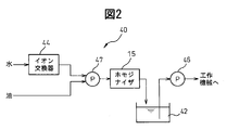
- FIG. 2 is a block diagram showing the first embodiment of the machining liquid supply apparatus.
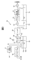
- FIG. 3 is a block diagram showing a second embodiment of the machining liquid supply apparatus.
- FIG. 4 is a cross-sectional view of a pressure type homogenizer.
- FIG. 1 shows a machine tool of the present embodiment.
- the machine tool of the present invention is not limited to the vertical machining center shown in FIG. 1, and a horizontal machining center, a turning center, and other machine tools are also included in the machine tool of the present invention. As shown in FIG. 1,
- the machine tool 1 includes a table 4 fixed on a base 3, a slide base (not shown) that slides along a linear motion guide on the base 3, and a slide base A column (not shown) that slides along the linear motion guide, a spindle head 5 that is supported by the column so as to be movable in the vertical direction, and a spindle 6 that is rotatably supported by the spindle head 5.
- the table 4 relatively move in three axial directions orthogonal to each other.
- An end mill 8 is attached to the main shaft 6, and a work 2 is attached to the table 4.
- the machine tool 1 introduces a processing fluid mixed with water and oil that does not contain an emulsifier and is pressurized to a predetermined pressure from a processing fluid supply device 10 outside the device, and uniformly disperses the oil in water by making the oil fine particles.
- a homogenizer 15 is provided.
- the homogenized machining fluid is supplied to the machining area via a coolant nozzle 13 connected to the machining fluid supply pipe 12. Without using the coolant nozzle 13, the homogenized machining fluid may be introduced into the main shaft 6 from the rear portion of the main shaft 6 and supplied to the processing region from the tip of the end mill 8 through the main shaft 6 and the end mill 8. .
- the homogenizer 15 is not limited to the pressure type homogenizer as shown in FIG.
- aqueous working fluid used for processing are not limited except that it does not contain an emulsifier.
- oil fatty acids such as oleic acid and stearic acid, animal and vegetable oils, mineral oils, synthetic oils, and mixed oils thereof can be used.
- water tap water or deionized water not containing hydroxide ions can be used.
- the mixing ratio of oil to water is, for example, 5% to 50% by weight, and preferably 10% to 30% by weight.
- fine powders of solid lubricants such as silica, boron nitride and diamond can also be included.
- the particle size of the fine powder is nanometer to micrometer order.
- deionized water ion-exchanged water, distilled water or pure water can be used.
- the pressure type homogenizer 15 includes a housing 19 having a processing chamber 20 therein, and a valve seat attached to the front end surface 21 a of the housing 19 with the valve seat surface 25 a facing the processing chamber 20. 25.
- the valve seat 25 has a machining fluid inlet 26 that is introduced into the homogenizer 15 at a high pressure.
- a narrow gap 35 is formed between the valve seat surface 25a and the valve front end surface 31a.
- the valve front end surface 31a has a circular shape with a diameter of 30 mm, for example.
- On the inner wall surface of the housing on the outer periphery of the gap 35 there is provided an impact ring 34 on which the mixed liquid of water and oil that has passed through the gap 35 collides at high speed.
- the impact ring 34 is a consumable part that is replaced when the high-pressure liquid mixture collides and wears, and is made of a wear-resistant material such as ceramics or cemented carbide.
- the housing 19 and the impact ring 34 are formed separately.
- the mixed liquid of water and oil is accelerated through the gap 35, and fine particles on the order of micrometer of oil are converted into water by the impact force when colliding with the impact ring 34 and cavitation caused by decompression in the processing chamber 20.
- a working fluid that is uniformly dispersed is produced.
- the housing 19 has a front end opening 22a and a rear end opening 22b communicating with the processing chamber 20, and a discharge port 22c for discharging the homogenized processing liquid.
- a valve seat 25 is attached to the front end surface 21a, and the mixed liquid is introduced into the processing chamber 20 from an introduction port 26 communicating with the front end opening 22a.
- a valve 31 is fitted into the rear end opening 22b, and a valve front end surface 31a faces the valve seat surface 25a with a predetermined gap 35 therebetween.
- the valve 31 is fitted so that no gap is generated between the valve 31 and the rear end opening 22b.
- the size of the gap 35 between the valve tip surface 31a and the valve seat surface 25a can be adjusted, and the gap 35 is set according to the oil particle diameter and viscosity of the introduced mixed liquid and the pressure of the working liquid. For example, in the case of oil with a large particle diameter and high viscosity, the gap 35 is set wide, and in the case of oil with a small particle diameter and low viscosity, the gap 35 is set narrow.
- the interval 35 between the valve tip surface 31a and the valve seat surface 25a is set to about 0.1 mm. .
- the gap 35 between the valve front end surface 31a and the valve seat surface 25a is narrow, the generation capacity of the homogenized machining fluid is reduced, and a sufficient amount of machining fluid cannot be supplied to the machining area. In such a case, it becomes possible to supply a sufficient amount of machining fluid by providing the machine tool 1 with a tank for storing the homogenized machining fluid.
- the homogenized machining liquid is discharged from the discharge port 22 c and supplied to the machining area via the machining liquid supply pipe 12.
- the valve seat 25 is made of the same material as the housing 19.
- the inlet 26 into which the mixed liquid pressurized to a predetermined pressure is introduced is formed so that the processing liquid outlet side is narrower than the inlet side.
- the liquid mixture is increased in velocity by flowing through the gap 35 from the inlet 26 and collides with the impact ring 34.
- the valve 31 is formed of the same material as that of the housing 19 like the valve seat 25.
- the valve 31 has a base 33 fixed to the rear end surface 21 b of the housing 19 and a protrusion 32 that is fitted into the rear end opening 22 b of the housing 19 and protrudes into the processing chamber 20.
- the front end surface of the protrusion 32 is formed as a valve surface 31a, and forms a gap 35 between the valve surface 31a and the opposing valve seat surface 25a.
- the machine tool 1 includes the homogenizer 15 that generates a machining liquid in which oil is uniformly dispersed in water. Therefore, water and oil that are not compatible without using an emulsifier. The particles can be kept in a state that is difficult to separate for a long time.
- the tool life can be significantly extended in machining of metals such as titanium alloy, nickel alloy, and aluminum alloy, whose tool life is shortened by chipping and wear.
- metals such as titanium alloy, nickel alloy, and aluminum alloy
- a tool life of about 4 times can be achieved compared to machining a titanium alloy with a carbide end mill.
- the homogenizer 15 is provided in the middle of the machining liquid supply conduit 12 from the machining liquid supply device 10 to the machining area, the machining liquid is water in the tank of the machining liquid supply device 10 over time.
- the homogenizer 15 can regenerate the processing liquid in which oil is uniformly dispersed in water, and stable processing can be performed.
- heat-treated oil having a high boiling point as defined in Japanese Industrial Standards JIS K2242, for example, oil particles dispersed in the working fluid are transformed into high-temperature workpieces, tools, and machining wastes. Even if it touches, it becomes difficult to vaporize and the performance deterioration as a processing liquid can be suppressed.
- oil with a low vaporization temperature (low boiling point) chipping of the tool is likely to occur due to impact when the oil particles vaporize, but the occurrence of chipping is also suppressed by using heat-treated oil with a high boiling point.
- the machining liquid supply apparatus 40 includes a homogenizer 15 and a tank 42 that stores the homogenized machining liquid.
- the homogenizer 15 the pressure type homogenizer shown in FIG. 4 described above can be used. Deionized water and oil ion-exchanged by the ion exchanger 44 are introduced into the homogenizer 15 of the present embodiment.
- FIG. 3 shows a second embodiment of the machining fluid supply apparatus of the present invention.
- the machining fluid supply device 50 of the present embodiment includes a primary tank 52 that collects the machining fluid used for machining, and is suitable for a machine tool that is automatically operated for a long time.
- the machining fluid is carried from the machine tool together with the machining waste, and is separated into machining waste and machining fluid by the lift-up chip conveyor 56.
- the separated working fluid is stored in the primary tank 52 together with deionized water for replenishment ion-exchanged by the ion exchanger 57 and new oil to be replenished.
- deionized water commercially available ones or those already produced by other methods can be used.
- the liquid is pumped up by the pump 58 and supplied to the filter 59.
- a rotary cyclone filter can be used as the filter 59, and fine machining debris is removed by the filter 59 and the machining fluid is stirred to some extent.
- the upper layer 52a is a layer mainly containing a large amount of oil
- the lower layer 52b is a layer mainly containing much water.
- the suction pipe for sucking the liquid from the upper layer 52a is formed so as to move up and down together with the float, and is configured so that the liquid can always be sucked from near the liquid surface.
- the mixed liquid of water and oil is temporarily stored in the secondary tank 53 via the filter 59.
- the pressurized working fluid pumped up from the secondary tank 53 by the pump 63 is introduced into the homogenizer 64 to produce a working fluid in which oil is uniformly dispersed in water.
- the generated processing liquid is sterilized by the ultraviolet irradiation device 65 and then stored in the tertiary tank 54.
- the ultraviolet irradiation device 65 is effective for preventing corrosion of the machining fluid.
- the machining liquid pumped from the tertiary tank 54 by the pump 66 is supplied to the machining area.
- the machining liquid supply device 50 of the present embodiment is a form suitable for a machine tool that is arranged on a production line and is operated for a long time. By using this machining supply device 50, water and oil of the machining liquid are not separated. In addition, continuous and stable processing can be performed. As described above, an aqueous working liquid in which oil is uniformly dispersed in water without using an emulsifier can be generated by a homogenizer. By using this machining fluid, the wear resistance and chipping resistance of tools in machining of all metals including titanium alloy, nickel alloy, aluminum alloy and the like can be increased, and the tool life can be extended. Thereby, productivity of metal processing increases and processing costs including tool costs can be reduced. In addition, this invention is not limited to the said embodiment, In the range which does not deviate from the main point of this invention, it can deform
Landscapes
- Physics & Mathematics (AREA)
- Fluid Mechanics (AREA)
- Engineering & Computer Science (AREA)
- Mechanical Engineering (AREA)
- Auxiliary Devices For Machine Tools (AREA)
- Lubricants (AREA)
Abstract
La présente invention concerne une machine-outil (1) destinée à usiner une pièce à usiner (2) en déplaçant de manière relative un outil (18) et la pièce à usiner (2), et pourvue d'un homogénéisateur (15) permettant d'aspirer de l'eau et de l'huile et de répartir de manière homogène l'huile dans l'eau. Ladite machine-outil usine la pièce à usiner tout en fournissant un fluide d'usinage généré par l'homogénéisateur (15) à une région d'usinage.
Priority Applications (2)
| Application Number | Priority Date | Filing Date | Title |
|---|---|---|---|
| US13/579,615 US9022175B2 (en) | 2010-02-24 | 2011-01-31 | Machine tool, working fluid supply apparatus, and working fluid |
| EP11747163.1A EP2540441B1 (fr) | 2010-02-24 | 2011-01-31 | Dispositif d'alimentation en fluide d'usinage |
Applications Claiming Priority (2)
| Application Number | Priority Date | Filing Date | Title |
|---|---|---|---|
| JP2010038316A JP2011173199A (ja) | 2010-02-24 | 2010-02-24 | 工作機械及び加工液供給装置、並びに加工液 |
| JP2010-038316 | 2010-02-24 |
Publications (1)
| Publication Number | Publication Date |
|---|---|
| WO2011105199A1 true WO2011105199A1 (fr) | 2011-09-01 |
Family
ID=44506616
Family Applications (1)
| Application Number | Title | Priority Date | Filing Date |
|---|---|---|---|
| PCT/JP2011/052450 Ceased WO2011105199A1 (fr) | 2010-02-24 | 2011-01-31 | Machine-outil, dispositif d'alimentation en fluide d'usinage et fluide d'usinage |
Country Status (4)
| Country | Link |
|---|---|
| US (1) | US9022175B2 (fr) |
| EP (1) | EP2540441B1 (fr) |
| JP (1) | JP2011173199A (fr) |
| WO (1) | WO2011105199A1 (fr) |
Families Citing this family (5)
| Publication number | Priority date | Publication date | Assignee | Title |
|---|---|---|---|---|
| US10120366B2 (en) * | 2014-09-08 | 2018-11-06 | Haas Automation, Inc. | Automatic machine tool coolant mixer |
| JP6302125B1 (ja) * | 2017-09-22 | 2018-03-28 | 株式会社松浦機械製作所 | 切削油の供給方法 |
| US10685863B2 (en) | 2018-04-27 | 2020-06-16 | Semiconductor Components Industries, Llc | Wafer thinning systems and related methods |
| JP6612401B1 (ja) * | 2018-07-26 | 2019-11-27 | 産機テクノス株式会社 | フィルタ式スラッジ回収装置 |
| JP7637413B2 (ja) * | 2021-11-29 | 2025-02-28 | 中部クリーン株式会社 | 水溶性切削油、水溶性切削油管理装置、および水溶性切削油管理方法 |
Citations (9)
| Publication number | Priority date | Publication date | Assignee | Title |
|---|---|---|---|---|
| JPH0478932U (fr) | 1990-11-16 | 1992-07-09 | ||
| JPH07115276B2 (ja) | 1990-09-25 | 1995-12-13 | 広和機械設計工業株式会社 | 切削液の補給装置 |
| JP2000045018A (ja) * | 1998-07-28 | 2000-02-15 | Idemitsu Kosan Co Ltd | 熱処理油組成物 |
| JP2003094283A (ja) * | 2002-08-06 | 2003-04-03 | Taiyu Kk | 切削加工方法及び切削油 |
| JP2004182879A (ja) * | 2002-12-04 | 2004-07-02 | Osamu Yamamoto | 高性能水溶性金属加工油剤 |
| JP3753728B2 (ja) | 2005-01-06 | 2006-03-08 | 修 山本 | 高性能水溶性金属加工油剤を用いた金属製品の製造方法及び水溶性金属加工油剤 |
| JP2007229894A (ja) * | 2006-03-03 | 2007-09-13 | Enomoto Bea Co Ltd | ミスト供給装置及びミスト供給方法 |
| WO2008108314A1 (fr) * | 2007-02-27 | 2008-09-12 | Nippon Oil Corporation | Procédé d'usinage et de meulage avec de l'huile contenant des gouttelettes d'eau ultrafines |
| JP2010006950A (ja) * | 2008-06-26 | 2010-01-14 | New Japan Chem Co Ltd | 工業用潤滑油組成物 |
Family Cites Families (8)
| Publication number | Priority date | Publication date | Assignee | Title |
|---|---|---|---|---|
| US2704363A (en) * | 1954-06-14 | 1955-03-15 | Socony Vacuum Oil Co Inc | Grease manufacture |
| JPH0478932A (ja) * | 1990-07-20 | 1992-03-12 | Nec Corp | 共有資源排他制御方式 |
| US5052618A (en) * | 1990-07-26 | 1991-10-01 | The United States Of America As Represented By The Secretary Of The Army | Method and apparatus for protecting crops from frost by jet-dispersed, microencapsulated aerosols |
| US5524465A (en) * | 1991-03-29 | 1996-06-11 | Hitachi, Ltd. | Work rolls crossing type mill, rolling system and rolling method |
| US7026364B2 (en) * | 2001-04-13 | 2006-04-11 | Organo Corporation | Ion exchanger |
| DE10130445A1 (de) * | 2001-06-23 | 2003-01-02 | Sms Demag Ag | Verfahren und Düsenanordnung zur breitenvariablen Walzspaltschmierung eines Walzgerüstes |
| JP3966501B2 (ja) * | 2002-03-18 | 2007-08-29 | オルガノ株式会社 | 超純水製造装置 |
| US7919438B2 (en) | 2006-02-28 | 2011-04-05 | The Board Of Trustees Of The University Of Illinois | Method and system for treating a metalworking operation |
-
2010
- 2010-02-24 JP JP2010038316A patent/JP2011173199A/ja active Pending
-
2011
- 2011-01-31 WO PCT/JP2011/052450 patent/WO2011105199A1/fr not_active Ceased
- 2011-01-31 EP EP11747163.1A patent/EP2540441B1/fr not_active Not-in-force
- 2011-01-31 US US13/579,615 patent/US9022175B2/en active Active
Patent Citations (9)
| Publication number | Priority date | Publication date | Assignee | Title |
|---|---|---|---|---|
| JPH07115276B2 (ja) | 1990-09-25 | 1995-12-13 | 広和機械設計工業株式会社 | 切削液の補給装置 |
| JPH0478932U (fr) | 1990-11-16 | 1992-07-09 | ||
| JP2000045018A (ja) * | 1998-07-28 | 2000-02-15 | Idemitsu Kosan Co Ltd | 熱処理油組成物 |
| JP2003094283A (ja) * | 2002-08-06 | 2003-04-03 | Taiyu Kk | 切削加工方法及び切削油 |
| JP2004182879A (ja) * | 2002-12-04 | 2004-07-02 | Osamu Yamamoto | 高性能水溶性金属加工油剤 |
| JP3753728B2 (ja) | 2005-01-06 | 2006-03-08 | 修 山本 | 高性能水溶性金属加工油剤を用いた金属製品の製造方法及び水溶性金属加工油剤 |
| JP2007229894A (ja) * | 2006-03-03 | 2007-09-13 | Enomoto Bea Co Ltd | ミスト供給装置及びミスト供給方法 |
| WO2008108314A1 (fr) * | 2007-02-27 | 2008-09-12 | Nippon Oil Corporation | Procédé d'usinage et de meulage avec de l'huile contenant des gouttelettes d'eau ultrafines |
| JP2010006950A (ja) * | 2008-06-26 | 2010-01-14 | New Japan Chem Co Ltd | 工業用潤滑油組成物 |
Non-Patent Citations (1)
| Title |
|---|
| See also references of EP2540441A4 * |
Also Published As
| Publication number | Publication date |
|---|---|
| US9022175B2 (en) | 2015-05-05 |
| JP2011173199A (ja) | 2011-09-08 |
| US20120315104A1 (en) | 2012-12-13 |
| EP2540441A4 (fr) | 2013-07-10 |
| EP2540441A1 (fr) | 2013-01-02 |
| EP2540441B1 (fr) | 2015-08-05 |
Similar Documents
| Publication | Publication Date | Title |
|---|---|---|
| Kui et al. | Recent progress and evolution of coolant usages in conventional machining methods: a comprehensive review | |
| Akkurt | The effect of cutting process on surface microstructure and hardness of pure and Al 6061 aluminium alloy | |
| Sharma et al. | Characterization and experimental investigation of Al2O3 nanoparticle based cutting fluid in turning of AISI 1040 steel under minimum quantity lubrication (MQL) | |
| Roy et al. | High speed turning of AISI 4140 steel using nanofluid through twin jet SQL system | |
| JP3354156B2 (ja) | 切削機械及び研削機械におけるクーラント液の供給方法と装置 | |
| Sharma et al. | Improved machining performance with nanoparticle enriched cutting fluids under minimum quantity lubrication (MQL) technique: a review | |
| Najiha et al. | Minimum quantity lubricant flow analysis in end milling processes: A computational fluid dynamics approach | |
| EP2540441B1 (fr) | Dispositif d'alimentation en fluide d'usinage | |
| EP1480786A1 (fr) | Buse poreuse lubrifiee pour jet a suspension de fluide abrasif | |
| Kananathan et al. | Nanofluid as coolant for grinding process: An overview | |
| Singh et al. | Green EDM strategies to minimize environmental impact and improve process efficiency | |
| WO2018127823A1 (fr) | Système de refroidissement par impact de pulvérisation de nano fluide atomisé et procédé de tournage dur | |
| Virdi et al. | A review on minimum quantity lubrication technique application and challenges in grinding process using environment-friendly nanofluids | |
| Dragičević | The application of alternative techniques for cooling, flushing and lubrication to improve efficiency of machining processes | |
| JP5208245B2 (ja) | 工作機械 | |
| Uysal | An experimental study on cutting temperature and burr in milling of ferritic stainless steel under MQL using nano graphene reinforced cutting fluid | |
| JP7428674B2 (ja) | 切削加工用クーラントの供給方法 | |
| Urmi et al. | Effects of minimum quantity lubrication technique in different machining processes-A comprehensive review | |
| Arantes et al. | The electrical discharge machining process aided by abrasive jet | |
| CN108436607A (zh) | 一种整体金属陶瓷铣刀的加工方法 | |
| Bee et al. | A review on influence of nano-fluid MQL in machining processes | |
| Sundriyal et al. | Study on different types of electric discharge machining methods: a review | |
| SE2350096A1 (en) | Manufacturing of hardfacings | |
| JP2020104230A (ja) | ワーク切削方法 | |
| CN109175421A (zh) | 一种超硬复合切削刀具 |
Legal Events
| Date | Code | Title | Description |
|---|---|---|---|
| 121 | Ep: the epo has been informed by wipo that ep was designated in this application |
Ref document number: 11747163 Country of ref document: EP Kind code of ref document: A1 |
|
| WWE | Wipo information: entry into national phase |
Ref document number: 2011747163 Country of ref document: EP |
|
| WWE | Wipo information: entry into national phase |
Ref document number: 13579615 Country of ref document: US |
|
| NENP | Non-entry into the national phase |
Ref country code: DE |