WO2011105231A1 - Dispositif de codage de coefficient de filtrage, dispositif de décodage de coefficient de filtrage, dispositif de codage vidéo, dispositif de décodage vidéo, et structure de données - Google Patents
Dispositif de codage de coefficient de filtrage, dispositif de décodage de coefficient de filtrage, dispositif de codage vidéo, dispositif de décodage vidéo, et structure de données Download PDFInfo
- Publication number
- WO2011105231A1 WO2011105231A1 PCT/JP2011/052923 JP2011052923W WO2011105231A1 WO 2011105231 A1 WO2011105231 A1 WO 2011105231A1 JP 2011052923 W JP2011052923 W JP 2011052923W WO 2011105231 A1 WO2011105231 A1 WO 2011105231A1
- Authority
- WO
- WIPO (PCT)
- Prior art keywords
- filter
- filter coefficient
- coefficient
- prediction
- value
- Prior art date
- Legal status (The legal status is an assumption and is not a legal conclusion. Google has not performed a legal analysis and makes no representation as to the accuracy of the status listed.)
- Ceased
Links
Images







Classifications
-
- H—ELECTRICITY
- H04—ELECTRIC COMMUNICATION TECHNIQUE
- H04N—PICTORIAL COMMUNICATION, e.g. TELEVISION
- H04N19/00—Methods or arrangements for coding, decoding, compressing or decompressing digital video signals
- H04N19/10—Methods or arrangements for coding, decoding, compressing or decompressing digital video signals using adaptive coding
- H04N19/134—Methods or arrangements for coding, decoding, compressing or decompressing digital video signals using adaptive coding characterised by the element, parameter or criterion affecting or controlling the adaptive coding
- H04N19/136—Incoming video signal characteristics or properties
- H04N19/14—Coding unit complexity, e.g. amount of activity or edge presence estimation
-
- H—ELECTRICITY
- H04—ELECTRIC COMMUNICATION TECHNIQUE
- H04N—PICTORIAL COMMUNICATION, e.g. TELEVISION
- H04N19/00—Methods or arrangements for coding, decoding, compressing or decompressing digital video signals
- H04N19/10—Methods or arrangements for coding, decoding, compressing or decompressing digital video signals using adaptive coding
- H04N19/102—Methods or arrangements for coding, decoding, compressing or decompressing digital video signals using adaptive coding characterised by the element, parameter or selection affected or controlled by the adaptive coding
- H04N19/117—Filters, e.g. for pre-processing or post-processing
-
- H—ELECTRICITY
- H04—ELECTRIC COMMUNICATION TECHNIQUE
- H04N—PICTORIAL COMMUNICATION, e.g. TELEVISION
- H04N19/00—Methods or arrangements for coding, decoding, compressing or decompressing digital video signals
- H04N19/10—Methods or arrangements for coding, decoding, compressing or decompressing digital video signals using adaptive coding
- H04N19/169—Methods or arrangements for coding, decoding, compressing or decompressing digital video signals using adaptive coding characterised by the coding unit, i.e. the structural portion or semantic portion of the video signal being the object or the subject of the adaptive coding
- H04N19/17—Methods or arrangements for coding, decoding, compressing or decompressing digital video signals using adaptive coding characterised by the coding unit, i.e. the structural portion or semantic portion of the video signal being the object or the subject of the adaptive coding the unit being an image region, e.g. an object
- H04N19/176—Methods or arrangements for coding, decoding, compressing or decompressing digital video signals using adaptive coding characterised by the coding unit, i.e. the structural portion or semantic portion of the video signal being the object or the subject of the adaptive coding the unit being an image region, e.g. an object the region being a block, e.g. a macroblock
-
- H—ELECTRICITY
- H04—ELECTRIC COMMUNICATION TECHNIQUE
- H04N—PICTORIAL COMMUNICATION, e.g. TELEVISION
- H04N19/00—Methods or arrangements for coding, decoding, compressing or decompressing digital video signals
- H04N19/60—Methods or arrangements for coding, decoding, compressing or decompressing digital video signals using transform coding
- H04N19/61—Methods or arrangements for coding, decoding, compressing or decompressing digital video signals using transform coding in combination with predictive coding
Definitions
- the present invention relates to a moving image encoding apparatus that encodes a moving image and generates encoded data.
- the present invention also relates to a moving picture decoding apparatus that decodes encoded data generated using such a moving picture encoding apparatus.
- the present invention also relates to a filter coefficient encoding apparatus that encodes a filter coefficient and a filter coefficient decoding apparatus that decodes the encoded filter coefficient.
- the present invention also relates to a data structure of encoded data generated by such a filter coefficient encoding device and referred to by such a filter coefficient decoding device.
- a moving image encoding device In order to efficiently transmit or record moving images, a moving image encoding device is used.
- a specific moving picture encoding method for example, H.264 is used.
- an image (picture) constituting a moving image is obtained by dividing a slice obtained by dividing an image, a macroblock obtained by dividing the slice, and a macroblock.
- a slice obtained by dividing an image
- a macroblock obtained by dividing the slice
- a macroblock obtained by dividing the slice
- a macroblock obtained by dividing the slice
- a macroblock is managed by a hierarchical structure composed of sub-blocks, and are usually encoded for each macroblock.
- AVC employs a configuration in which a deblocking filter that acts on a (local) decoded image is provided and a predicted image is generated with reference to the (local) decoded image with reduced block noise.
- the KTA software employs a configuration in which an ALF (Adaptive Loop Filter) is provided after the deblocking filter and a predicted image is generated with reference to the (local) decoded image after application of ALF (Non-patent Document 1). reference).
- the filter coefficient of ALF is adaptively determined so that the error between the decoded image to which ALF is applied and the original image is minimized for each frame or slice on the decoded image.
- the KTA software adopts a configuration that predictively encodes ALF filter coefficients. That is, the difference between the filter coefficient group used for filtering of the encoding / decoding target frame and the prediction filter coefficient group predicted from the filter coefficient group used for filtering of the encoded / decoded frame is encoded.
- a configuration provided to the image decoding apparatus is employed.
- KTA a filter coefficient group used for filtering of encoded / decoded frames is used as it is as a prediction filter coefficient group.
- the filter coefficient group used for filtering of the encoded / decoded frame is the prediction filter coefficient group
- the encoding efficiency does not increase as expected even if predictive encoding is performed, or On the contrary, there is a problem that encoding efficiency is lowered when predictive encoding is performed.
- the present invention has been made in view of the above-described problems, and an object of the present invention is to improve encoding efficiency compared to a conventional configuration in which a filter coefficient group used for filtering of encoded / decoded frames is a prediction filter coefficient group. It is to implement
- the filter coefficient of the peripheral part (filter coefficient multiplied by the pixel value of the peripheral part of the input image) is a frame compared with the filter coefficient of central part (the filter coefficient multiplied by the pixel value of the central part of the input image).
- the correlation was small. Even if predictive encoding is performed, the encoding efficiency does not increase as expected, or the predictive encoding is rather deteriorated. This is also considered to be because predictive coding was performed in the same manner as the filter coefficient at the center of the high correlation between frames.
- the present invention has been made based on this finding.
- the filter coefficient encoding apparatus encodes a difference between a filter coefficient of a target filter acting on a target image and a predicted value of the filter coefficient.
- a prediction value generating means for generating the predicted value by multiplying each filter coefficient of the reference filter acting on the reference image by a weighting coefficient.
- the weighting factor to be multiplied is configured to be closer to 0 than the weighting factor to be multiplied by the filter coefficient at the center.
- the predicted value of the filter coefficient h of the target filter is generated by multiplying the filter coefficient h ′ of the reference filter by the weight coefficient a, and the difference h ⁇ between the filter coefficient h of the target filter and the predicted value ah ′.
- ah ′ is encoded.
- the weighting coefficient a (peripheral part) multiplied by the peripheral coefficient h ′ having a low inter-frame correlation is closer to 0 than the weighting coefficient a (center part) multiplying the peripheral coefficient h ′ having a high inter-frame correlation. I am doing so. For this reason, it is possible to effectively avoid a situation in which the coding efficiency of predictive coding decreases due to
- Another filter coefficient encoding apparatus is a filter coefficient encoding apparatus that encodes a residual of a filter coefficient of a target filter acting on a target image with a predicted value for the filter coefficient.
- 1 is a first predicted value generation means for generating a first predicted value by multiplying each filter coefficient of the reference filter acting on the filter coefficient of the peripheral part, and the weighting coefficient to be multiplied by the filter coefficient of the peripheral part is the filter of the central part
- a first prediction value generating means configured to be smaller than a weighting coefficient to be multiplied by the coefficient; a second prediction value generating means for setting each filter coefficient of the reference filter to a second prediction value; and the weight
- the serial second predicted value is characterized by comprising a prediction value setting means for setting to the predicted value.
- the filter coefficient itself of the reference filter can be used as the predicted value, so that the amount of calculation required to decode the filter coefficient residual is reduced. There is an effect that can be.
- Another filter coefficient encoding apparatus is a filter coefficient encoding apparatus that encodes a residual of a filter coefficient of a target filter acting on a target image with a predicted value for the filter coefficient.
- 1 is a first predicted value generation means for generating a first predicted value by multiplying each filter coefficient of the reference filter acting on the filter coefficient of the peripheral part, and the weighting coefficient to be multiplied by the filter coefficient of the peripheral part is the filter of the central part
- a first prediction value generation unit configured to be smaller than a weighting factor to be multiplied by the coefficient
- a second prediction value generation unit that sets each filter coefficient of the reference filter to a second prediction value
- the first Prediction value setting means for setting one of the predicted values or the second predicted value having a smaller residual with the filter coefficient as the predicted value. It is characterized.
- the residual of the filter coefficient generated by using the first predicted value or the second predicted value having a smaller residual with the filter coefficient as the predicted value is encoded. Therefore, there is an effect that the code amount of the filter coefficient residual can be further reduced.
- the moving picture coding apparatus includes the filter coefficient coding apparatus, and performs filtering using the filter coefficient of the target filter on a locally decoded image.
- the above moving picture coding apparatus has the same effects as the filter coefficient coding apparatus.
- the filter coefficient decoding apparatus restores the filter coefficient of the target filter acting on the target image by adding a prediction value to the filter coefficient residual obtained by decoding the encoded data.
- the coefficient decoding apparatus includes a predicted value generating unit that generates the predicted value by multiplying each filter coefficient of the reference filter that acts on the reference image by a weighting coefficient, and the predicted value generating unit includes a filter coefficient in a peripheral portion.
- the weighting factor to be multiplied by is configured to be closer to 0 than the weighting factor to be multiplied by the filter coefficient at the center.
- the filter coefficient encoding device having a configuration corresponding to the above configuration generates a prediction value of the filter coefficient h of the target filter by multiplying the filter coefficient h ′ of the reference filter by the weight coefficient a, and the filter coefficient of the target filter
- the difference h ⁇ ah ′ between h and the predicted value ah ′ can be encoded, and the weight coefficient a (peripheral part) multiplied by the peripheral coefficient h ′ with low inter-frame correlation is represented as the peripheral part with high inter-frame correlation. It is possible to make it closer to 0 than the weighting coefficient a (center part) multiplied by the coefficient h ′. For this reason, it is possible to effectively avoid a situation in which the coding efficiency of predictive coding decreases due to
- the filter coefficient decoding apparatus having the above-described configuration can decode the encoded data with a small code amount generated as described above.
- Another filter coefficient decoding apparatus adds a predicted value to a filter coefficient residual obtained by decoding encoded data, with a filter coefficient of the target filter acting on the target image.
- a first prediction value generation means for generating a first prediction value by multiplying each filter coefficient of a reference filter acting on a reference image by a weighting coefficient, the filter coefficient of a peripheral portion
- a first prediction value generating means configured to make the weighting coefficient to be multiplied by a weighting coefficient to be multiplied by the filter coefficient in the central portion, and a second prediction value for setting each filter coefficient of the reference filter to a second prediction value.
- the first predicted value is set as the predicted value, and the weighted coefficient If the value is above a predetermined value or more, and the second predicted value and characterized by comprising a prediction value setting means for setting to the predicted value.
- the filter coefficient encoding device having a configuration corresponding to the above configuration, when the value of the weighting factor is smaller than a predetermined value, the weighting factor is calculated as the predicted value. If the weight coefficient value is equal to or greater than a predetermined value, the filter coefficient of the reference filter itself can be used as the predicted value, so that the filter coefficient residual is decoded. It is possible to reduce the amount of calculation required to do.
- the filter coefficient decoding apparatus having the above configuration has an effect of being able to decode encoded data with a small code amount generated as described above.
- Another filter coefficient decoding apparatus adds a predicted value to a filter coefficient residual obtained by decoding encoded data, with a filter coefficient of the target filter acting on the target image.
- a first prediction value generation means for generating a first prediction value by multiplying each filter coefficient of a reference filter acting on a reference image by a weighting coefficient, the filter coefficient of a peripheral portion
- a first prediction value generating means configured to make the weighting coefficient to be multiplied by a weighting coefficient to be multiplied by the filter coefficient in the central portion, and a second prediction value for setting each filter coefficient of the reference filter to a second prediction value.
- the two predicted value generation means and the first predicted value or the second predicted value the one having a smaller residual with the filter coefficient is the predicted value. It is characterized by comprising a prediction value setting means for setting.
- the first predicted value or the second predicted value that has a smaller residual with the filter coefficient is the predicted value. Since the residual of the filter coefficient generated as can be encoded, the code amount of the residual of the filter coefficient can be further reduced.
- the filter coefficient decoding apparatus having the above configuration has an effect of being able to decode encoded data with a small code amount generated as described above.
- the moving picture decoding apparatus includes the filter coefficient decoding apparatus, and performs filtering using the filter coefficient of the target filter on the local decoded image.
- the above moving picture decoding apparatus has the same effects as the filter coefficient decoding apparatus.
- the data structure of the encoded data according to the present invention is encoded data data obtained by encoding a residual of a filter coefficient of a target filter acting on a target image with a predicted value for the filter coefficient.
- the structure includes weight coefficient information that specifies weight coefficients to be multiplied by each filter coefficient of the reference filter that acts on the reference image, and multiplies the peripheral filter coefficients. It is characterized in that the weighting factor is smaller than the weighting factor by which the filter coefficient at the center is multiplied.
- the filter coefficient in the peripheral part tends to have a smaller correlation between frames than the filter coefficient in the central part.
- the code amount of the filter coefficient residual can be reduced by making the weight coefficient multiplied by the filter coefficient in the peripheral part smaller than the weight coefficient multiplied by the filter coefficient in the central part.
- the encoded data having the above configuration is encoded data with a small code amount including such a weight coefficient.
- the filter coefficient decoding apparatus that decodes the encoded data having the above configuration can decode the encoded data with a small code amount of the filter coefficient residual by referring to the weight coefficient information.
- the filter coefficient encoding apparatus is a filter coefficient encoding apparatus that encodes a residual between a filter coefficient of a target filter acting on a target image and a prediction value for the filter coefficient.
- a prediction value generating unit configured to generate the prediction value by multiplying each filter coefficient of the reference filter acting on the image by a weighting coefficient, and the prediction value generating unit includes a weighting coefficient to be multiplied by a filter coefficient in a peripheral portion; It is characterized by being configured so as to be smaller than the weighting coefficient multiplied by the filter coefficient at the center.
- the filter coefficient encoding apparatus configured as described above, the filter coefficient having higher encoding efficiency than the conventional configuration in which the filter coefficient group used for filtering of the encoded / decoded frame is the prediction filter coefficient group.
- An encoding device can be realized.
- Embodiment 1 (Moving picture decoding apparatus 1)
- the moving picture decoding apparatus 1 includes H.264 as a part thereof. H.264 / MPEG-4 AVC, and a decoding device including technology adopted in KTA software.
- FIG. 1 is a block diagram showing a configuration of the moving picture decoding apparatus 1.
- the moving picture decoding apparatus 1 includes a variable length code decoding unit 13, a motion vector restoration unit 14, a buffer memory 15, an inter prediction image generation unit 16, an intra prediction image generation unit 17, and a prediction method determination unit 18. , An inverse quantization / inverse transform unit 19, an adder 20, a deblocking filter 50, and an adaptive filter 100.
- the video decoding device 1 generates and outputs a decoded image # 2 by decoding the encoded data # 1.
- the generation of decoded image # 2 by the moving image decoding apparatus 1 is performed in units of macroblocks or subblocks constituting a frame.
- variable length code decoding unit 13 performs variable length decoding on the encoded data # 1, and performs differential motion vector # 13a, side information # 13b, quantized prediction residual data # 13c, filter coefficient residual # 13d, and filter parameters. Information # 13e is output.
- the side information # 13b includes a prediction mode, a motion vector, a reference image index, a quantization parameter, and the like.
- the filter parameter information # 13e includes a parameter indicating the number of reference pixels for filtering (the number of taps) and information related to a parameter for specifying on / off of filtering.
- the filter parameter information # 13e may include a weighting coefficient used for prediction of the filter coefficient, as will be described later.
- the motion vector restoration unit 14 decodes the motion vector # 14 for the target sub-block from the difference motion vector # 13a and the motion vector # 15a that has already been decoded and stored in the buffer memory 15.
- the buffer memory 15 stores output image data # 100 output from the adaptive filter 100, motion vector # 14, and side information # 13b.
- the inter prediction image generation unit 16 is decoded by the motion vector restoration unit 14 and based on the motion vector # 15c that has passed through the buffer memory 15 and the reference image # 15d stored in the buffer memory 15, the inter prediction image # 16. Is generated.
- the generation of the inter prediction image # 16 is performed in units of macroblocks or subblocks, for example.
- the motion vector # 15c may be the same motion vector as the motion vector # 14.
- the reference image # 15d corresponds to output image data # 100 output from an application filter 100 described later.
- the intra-predicted image generation unit 17 generates an intra-predicted image # 17 from the local decoded image # 15b stored in the buffer memory 15. More specifically, the intra predicted image generation unit 17 generates an image on the prediction target macroblock of the intra predicted image # 17 using the local decoded image # 15b in the same frame as the prediction target macroblock.
- the prediction method determination unit 18 selects one of the intra prediction image # 17 and the inter prediction image # 16 based on the prediction mode information included in the side information # 13b, and outputs the selected prediction image # 18. To do.
- Quantization prediction residual data # 13c is supplied to the inverse quantization / inverse transform unit 19 in units of sub-blocks.
- the inverse quantization / inverse transform unit 19 transforms the quantized prediction residual data # 13c into a frequency component by performing inverse quantization, and further performs inverse DCT (Discrete Cosine Transform) transform on the frequency component. As a result, a prediction residual # 19 is generated and output.
- inverse DCT Discrete Cosine Transform
- the adder 20 generates a decoded image # 2 by adding the prediction residual # 19 and the prediction image # 18, and outputs the decoded image # 2.
- the output decoded image # 2 is also supplied to the deblocking filter 50.
- the deblocking filter 50 performs deblocking processing for reducing block distortion at the block boundary or macroblock boundary on the decoded image # 2.
- the image data subjected to the deblocking process is output as a deblocked image # 50.
- the adaptive filter 100 calculates a filter coefficient based on the filter coefficient residual # 13d decoded from the encoded data # 1, and performs filtering using the filter coefficient on the deblocked image # 50, thereby outputting an output image.
- Data # 100 is generated.
- the output image data # 100 is supplied to the buffer memory 15.
- the filtering process in adaptive filter 100 is performed based on side information # 13b decoded from encoded data # 1 and parameters included in filter parameter information # 13e.
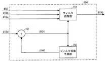
- FIG. 2 is a block diagram showing the configuration of the adaptive filter 100.
- the adaptive filter 100 includes a filter processing unit 110, a filter coefficient prediction unit 140, and an adder 101.
- the adder 101 generates the filter coefficient # 101 by adding the filter coefficient residual # 13d decoded from the encoded data # 1 and the prediction filter coefficient # 140 output from the filter coefficient prediction unit 140, Output.
- the filter processing unit 110 generates output image data # 100 by filtering the deblocked image # 50 using the filter coefficient # 101 based on the side information # 13b and the filter parameter information # 13e. And output.
- the filter processing unit 110 for example, each pixel value of the deblocked image # 50 and the filter coefficient # of each pixel value included in the filter reference area specified by the filter parameter information # 13e.
- Each pixel value of output image data # 100 is calculated and output by taking a weighted linear sum based on 101 and further adding an offset based on filter coefficient # 101.
- the filter processing unit 110 calculates the pixel value S0 (x ′, y ′) at the coordinates (x ′, y ′) of the output image data # 100 by a weighted linear sum represented by Expression (1). To do.
- SI (x, y) represents the pixel value at the coordinates (x, y) of the deblocked image # 50, and h (i, j) is multiplied by the pixel value SI (x + i, y + j). It represents the filter coefficient.
- O represents an offset value.
- the filter coefficient h (i, j) corresponds to the filter coefficient # 101.
- R represents a filter reference area that is a set of relative coordinates to be subjected to the weighted linear sum. As described above, the filter reference region R is determined based on, for example, the filter parameter information # 13e. Also, the coordinates (x ′, y ′) and the coordinates (x, y) may be the same coordinates or different coordinates.
- Output image data # 100 composed of the pixel value S0 (x ′, y ′) calculated using the above equation (1) is supplied to the buffer memory 15.
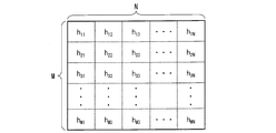
- the filtering process in the filter processing unit 110 is generally performed when the filter reference region R is M ⁇ N taps, and the filter coefficient matrix H is an M ⁇ N matrix having filter coefficients h (i, j) as components.
- hij corresponds to the filter coefficient h (i, j) (the same applies hereinafter).
- FIG. 3 is a diagram showing each pixel included in the filter reference region R and a filter coefficient h (i, j) corresponding to each pixel when the filter reference region R is M ⁇ N taps. . As shown in FIG. 3, a filter coefficient h (i, j) is assigned to each pixel in the M ⁇ N tap filter reference region R.
- the filter coefficient prediction unit 140 calculates the prediction filter coefficient # 140 based on the filter coefficient already decoded in the decoded frame or the filter coefficient already decoded in the frame being decoded among the filter coefficients # 101. .
- the prediction filter coefficient # 140 is output to the adder 101.
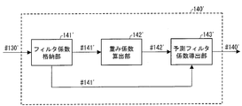
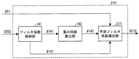
- FIG. 4 is a block diagram showing a configuration of the filter coefficient prediction unit 140.
- the filter coefficient prediction unit 140 includes a filter coefficient storage unit 141, a weight coefficient calculation unit 142, and a prediction filter coefficient derivation unit 143.
- the filter coefficient storage unit 141 stores the filter coefficient # 101 output from the adder 101. Further, the filter coefficient storage unit 141 is supplied with the filter coefficient # 141, which is a decoded filter coefficient, to the weighting coefficient calculation unit 142.
- filter coefficients # 141 are filter coefficients # 141a
- filter coefficients already decoded in the frame being decoded are filter coefficients # This is expressed as 141b.
- the filter coefficient matrix H ′ having the filter coefficient # 141 as a component can be expressed by the following equation (3).
- the filter coefficient h ′ (i, j) corresponds to the filter coefficient # 141.
- the weight coefficient calculation unit 142 calculates a weight coefficient a (i, j) to be multiplied by each component h ′ (i, j) of the filter coefficient matrix H ′. More specifically, the weighting factor calculation unit 142 divides the filter reference region R into a plurality of subregions, and calculates a weighting factor a (i, j) for each subregion. The calculated weighting coefficient # 142 is output to the prediction filter coefficient deriving unit 143.
- the weighting coefficient matrix A having the weighting coefficient a (i, j) in each component can be expressed by the following equation (4) when the filter reference region R is M ⁇ N taps.
- the prediction filter coefficient deriving unit 143 includes a filter coefficient h ′ (i, j) already used in the filtering process for the decoded frame among the filter coefficients stored in the filter coefficient storage unit 141, and a weight coefficient calculation unit. Based on the weighting coefficient a (i, j) calculated by 142, the prediction filter coefficient p (i, j) is derived.
- the prediction filter coefficient matrix P having the prediction filter coefficient p (i, j) as a component can be expressed by the following equation (5), for example.
- the prediction filter coefficient deriving unit 143 calculates the prediction filter coefficient p (i, j), and the product of the weight coefficient a (i, j) and the filter coefficient h ′ (i, j). Derived by taking
- the prediction filter coefficient corresponding to the center pixel of the filter reference region R is the filter coefficient # 141b already decoded for the pixels other than the center of the filter reference region R. It is good also as a structure derived
- the prediction filter coefficient deriving unit 143 derives the prediction filter coefficient p_center for the center pixel of the filter reference region R among the prediction filter coefficients p (i, j) using the following equation (6). It is good.
- the sum regarding i and j is the sum for the region R ′ excluding the central pixel in the filter reference region R.
- the prediction accuracy of the prediction filter coefficient is increased by using the tendency that the sum of the filter coefficients h (i, j) in the filter reference region R is close to 1. It can be improved effectively.
- a value corresponding to the quantized coefficients may be used instead of taking a difference from 1. For example, since the filter coefficient quantized with 1/256 as a step has been multiplied by 256, the difference from 256 may be taken.
- the prediction filter coefficient p_center for the center pixel is derived by taking the difference from the value corresponding to the quantization step, instead of taking the difference from 1. What is necessary is just to be the structure to do.
- the prediction filter coefficient p_center for the center pixel can be derived. With such a configuration, the code amount of the filter coefficient residual # 13d included in the encoded data # 1 can be reduced.
- the filter coefficient residual # included in the encoded data # 1 is generated by generating the prediction filter coefficient using the same expression as Expression (6).
- the code amount of 13d can be reduced.
- the moving picture decoding apparatus 1 can decode the encoded data # 1 with a small code amount of the filter coefficient residual # 13d by adopting the above configuration.
- the prediction filter coefficient p (i, j) derived by the prediction filter coefficient deriving unit 143 is supplied to the adder 101 as the prediction filter coefficient # 140.
- the variable length decoding unit 13, the adder 101, and the filter coefficient prediction unit 140 are based on the filter coefficient residual # 13d included in the encoded data # 1.
- a filter coefficient decoding device that decodes the filter coefficient # 101 includes such a filter coefficient decoding device, and is a video decoding device that performs filtering using the filter coefficient # 101 on the deblocked image # 50. It can also be expressed.
- the filter coefficient prediction unit 140 performs any one of the following calculation processes (specific example 1-1) to (specific example 1-5) according to the configuration of the encoded data # 1.
- the calculation process in this example can be suitably applied, for example, when decoding encoded data # 1 configured as described later (Configuration Example 1-1).
- the weight coefficient calculation unit 142 first divides the filter reference region R into a plurality of groups (sub-regions) from the center of the filter reference region R toward the periphery.
- FIG. 5 is a diagram illustrating an example of an arrangement of each group constituting the filter reference region R divided by the weight coefficient calculation unit 142 when the filter reference region R is 9 ⁇ 9 taps.
- the weighting coefficient calculation unit 142 moves the filter reference region R to group 5, group 4, group 3, group 2, and group 1 from the center of the filter reference region R to the periphery. To divide.
- the group 5 includes a pixel at the center of the filter reference region R (hereinafter referred to as a pixel Pc).
- Group 4 is composed of pixels inscribed in the outer edge of the 3 ⁇ 3 tap region centered on pixel Pc
- Group 3 is a pixel inscribed in the outer edge of the 5 ⁇ 5 tap region centered on pixel Pc.
- Group 2 is composed of pixels inscribed in the outer edge of the 7 ⁇ 7 tap area centered on the pixel Pc
- Group 1 is located on the outer edge of the 9 ⁇ 9 tap area centered on the pixel Pc. It consists of pixels in contact.
- the weighting factor calculation unit 142 sets the weighting factor a (i, j) for each group to the value of the weighting factor included in the filter parameter information # 13e.
- the weighting factor a_gr1 for group 1 is 1/4
- the weighting factor a_gr2 for group 2 is 1/2
- the weighting factor a_gr3 for group 3 is 5 /. 8.
- the weight coefficient for group 1 is set to 1/4
- the weight coefficient for group 2 is set to 1/2
- the weight coefficient for group 3 is set to 5 / 8
- the weighting factor for group 4 is set to 3/4
- the weighting factor for group 5 is set to 1.
- the weighting factor calculation unit 142 outputs the weighting factor for each group set in this way as the weighting factor # 142 to the prediction filter factor deriving unit 143, and the prediction filter factor deriving unit 143 outputs the weighting factor # 142.
- predictive filter coefficient # 140 is derived. As described above, when each weighting factor is a multiple of 1/8, the weighting factor calculation unit 142 multiplies each group by 2, 4, 5, 6, and 8 and adds 4 for rounding. However, the weight coefficient # 142 may be calculated using integer arithmetic that shifts right by 3 bits.
- the value of the weighting factor included in the filter parameter information # 13e is not limited to the above example, but in the moving picture encoding device that generates the encoded data # 1, the code of the filter coefficient residual # 13d It is preferably a value calculated so as to reduce the amount.
- the prediction filter coefficient # 140 can be derived based on the filter coefficient residual # 13d with a small code amount in this way.
- the prediction filter coefficient deriving unit 143 may be configured to derive the prediction filter coefficient for the center pixel of the filter reference region R using Expression (6).
- the prediction filter coefficient # 140 can be derived based on the encoded data # 1 having a smaller code amount by using the equation (6).
- the moving picture decoding apparatus 1 uses the tendency that the sum of the filter coefficients h (i, j) in the filter reference region R is close to 1 as described above by using Equation (6). Since the prediction accuracy of the filter coefficient can be effectively improved, it is possible to decode the encoded data # 1 with a small code amount of the filter coefficient residual # 13d.
- the weighting factor calculation unit 142 sets the weighting factor a (i, j) for each group to the value of the weighting factor included in the filter parameter information # 13e. It is not limited to.
- the weight coefficient calculation unit 142 may be configured to set the weight coefficient a (i, j) for each group to the value of the weight coefficient recorded in advance in the memory.
- the prediction filter coefficient # 140 can be derived even when the filter parameter information # 13e does not include the value of the weighting coefficient.
- the weight coefficient value recorded in the memory in advance is preferably the same value as the weight coefficient value used in the moving picture encoding apparatus that generates the encoded data # 1.
- the filter reference region R is 9 ⁇ 9 taps.
- the present invention is not limited to this, and in general, the filter reference region R is It can be applied to the case of M ⁇ N taps.
- the method of dividing the filter reference region R by the weight coefficient calculation unit 142 is not limited to the above example, and an optimal dividing method may be adopted according to the characteristics of the filter coefficient. For example, it is also preferable to divide the weight coefficient for each filter coefficient.
- the filter coefficient prediction unit 140 may divide the filter reference region R into a plurality of sub-regions and derive the prediction filter coefficient # 140 using the weighting factor set for each sub-region. Therefore, the moving image decoding apparatus 1 can generate the decoded image # 2 based on the encoded data # 1 with a small code amount of the filter coefficient residual # 13d.
- the calculation process in this example can be suitably applied, for example, when decoding encoded data # 1 configured as described later (Configuration Example 1-2).
- the weight coefficient calculation unit 142 first divides the filter reference region R into a plurality of groups from the center of the filter reference region R toward the peripheral part, as in (Specific example 1-1).
- the weighting factor calculation unit 142 first calculates the weighting factor a_grG ′ (s) for the region on the decoded frame and the region of the group G using the already decoded filter coefficients.
- the index s in a_grG ′ (s) indicates that the frame is s frames before counting from the prediction target frame.
- the frame before s frames counted from the prediction target frame is referred to as a frame s.
- the weight coefficient calculation unit 142 uses the weight coefficient a_grG ′ (s) for the frame s and the filter referred to for calculating the predicted value of the filter coefficient h (i, j) (s) for the frame s.
- the coefficient h (i, j) (s_prev) and the filter coefficient h (i, j) (s) for the frame s the following equation (7) is used for calculation.
- the sum regarding i and j is the sum for the reference region G corresponding to the group G in the filter reference region R.
- the weighting factor calculation unit 142 calculates the weighting factor a_grG using the representative value of the calculated weighting factor a_grG ′ (s).
- the representative value for example, a median value of the weighting coefficients a_grG ′ (s) calculated for a plurality of frames can be used.
- the weighting factor calculation unit 142 calculates the weighting factor a_grG by the following equation (8).
- a_grG median (a_grG ′ (1), a_grG ′ (2),..., a_grG ′ (F))
- median represents taking the median of the values in parentheses.
- the weighting factor calculation unit 142 is a weighting factor calculated for each frame from one frame before to F frames before counting from the prediction target frame, and the weighting factor a_grG ′ (1) ⁇
- the median value of a_grG ′ (F) is set to the weight coefficient a_grG.
- F a predetermined value may be used, or for example, a different value may be used depending on the position of the filter reference region R in the frame.
- the weighting coefficient used for the prediction of the filter coefficient h (i, j) (s) for the frame s may be used as it is.
- the weighting factor calculation unit 142 outputs the weighting factor a_grG for each group set in this way as the weighting factor # 142 to the prediction filter factor deriving unit 143.
- the prediction filter factor deriving unit 143 outputs the weighting factor # 143. 142 is used to derive prediction filter coefficient # 140.
- the weight coefficient for each group constituting the filter reference region R has a correlation between frames. That is, the weighting coefficient already calculated for each region on the decoded frame tends to be an appropriate value for deriving the prediction filter coefficient for the prediction target frame. Therefore, in the moving picture encoding apparatus that generates the encoded data # 1, the filter coefficient residual # included in the encoded data # 1 is generated by generating a prediction filter coefficient using an expression similar to the expression (8). The code amount of 13d can be reduced. In addition, the filter coefficient prediction unit 140 in the moving image decoding apparatus 1 performs the operation of this example, thereby calculating the prediction filter coefficient # 140 based on the filter coefficient residual # 13d generated in this way with a small code amount. Can be derived.
- the prediction filter coefficient deriving unit 143 may be configured to derive the prediction filter coefficient for the center pixel of the filter reference region R using Expression (6).
- the weighting factor calculation unit 142 includes a memory that stores a weighting factor that has already been calculated for each region on a decoded frame. It becomes.
- the calculation processing in this example can be suitably applied to, for example, decoding encoded data # 1 configured as described later (Configuration Example 1-3).
- the weighting factor calculation unit 142 calculates the weighting factor for each group constituting the filter reference region R by using the average value as the representative value in the above-described (specific example 1-2).
- the weighting factor calculation unit 142 calculates the weighting factor a_grG by the following equation (9) instead of the equation (8).
- Other operations of the weight coefficient calculating unit 142 are the same as those described in the specific example 1-2.
- the index s in a_grG ′ (s) indicates the frame before s frames, counted from the prediction target frame, as in (Specific Example 1-2).
- the weighting factor calculation unit 142 is a weighting factor calculated for each frame from one frame before to F frames before counting from the prediction target frame, and the weighting factor a_grG ′ (1) ⁇
- the average value of a_grG ′ (F) is set to the weight coefficient a_grG.
- the weight coefficient for each group constituting the filter reference region R has a correlation between frames. That is, the weighting coefficient already calculated for each region on the decoded frame tends to be an appropriate value for deriving the prediction filter coefficient for the prediction target frame. Therefore, in the moving picture encoding apparatus that generates the encoded data # 1, the filter coefficient residual # included in the encoded data # 1 is generated by generating a prediction filter coefficient using an expression similar to the expression (9). The code amount of 13d can be reduced. In addition, the filter coefficient prediction unit 140 in the moving image decoding apparatus 1 performs the operation of this example, thereby calculating the prediction filter coefficient # 140 based on the filter coefficient residual # 13d generated in this way with a small code amount. Can be derived.
- the weighting factor calculation unit 142 includes a memory that stores a weighting factor that has already been calculated for each region on a decoded frame. It becomes.
- the calculation process in this example can be suitably applied, for example, when decoding encoded data # 1 configured as described later (Configuration Example 1-4).
- the weight coefficient calculation unit 142 first divides the filter reference region R into a plurality of groups from the center of the filter reference region R toward the peripheral part, as in (Specific example 1-1).
- the weighting factor calculation unit 142 calculates the weighting factor a (i, j) by the least square method.
- the weighting factor calculation unit 142 calculates the weighting factor a (i, j) so as to minimize the square error E1 represented by the following equation (10).
- the variable t represents the frame number associated with each frame. That is, the filter coefficient h (i, j) (t) represents a filter coefficient used for filtering a frame whose frame number is t. O represents an offset.
- h (i, j) (t_prev) is a decoded filter coefficient, which is a filter coefficient referred to for calculation of a prediction filter coefficient corresponding to the filter coefficient h (i, j) (t). Represents.
- the weight coefficient a (i, j) may be calculated so as to minimize the square error E1 obtained by taking the sum of -1.
- the weight coefficient calculation unit 142 minimizes the square error E1 obtained by summing the frames from the smallest frame interval to the prediction target frame to the current frame among the decoded intra-frame encoded frames (intra frames).
- the weighting factor calculation unit 142 averages the weighting factor a (i, j) calculated using the least square method for each group constituting the filter reference region, thereby obtaining the weighting factor a_grG for each group. Calculated and output to the prediction filter coefficient deriving unit 143 as the weight coefficient # 142.
- the prediction filter coefficient deriving unit 143 derives the prediction filter coefficient # 140 using the weighting coefficient # 142.
- the prediction filter coefficient is calculated based on the least square method using the same equation as the equation (10), so that it is included in the encoded data # 1.
- the code amount of the filter coefficient residual # 13d can be reduced.
- the filter coefficient prediction unit 140 in the moving image decoding apparatus 1 performs the operation of this example, thereby calculating the prediction filter coefficient # 140 based on the filter coefficient residual # 13d generated in this way with a small code amount. Can be derived.
- the weighting coefficient calculation unit 142 takes the median value of the weighting coefficient a (i, j) calculated by using the least square method for each group constituting the filter reference region, so that the weighting coefficient a_grG for each group is obtained. It is good also as a structure which calculates.
- the weight coefficient calculation unit 142 may be configured to apply the least square method directly to each group without taking the average value or the median value.
- the weighting factor calculation unit 142 may be configured to calculate the weighting factor a_grG of the group G so as to minimize the square error E2 represented by the following equation (11).
- the sum regarding i and j represents the sum for the reference region G corresponding to the group G in the filter reference region R.
- O represents an offset.
- the prediction filter coefficient deriving unit 143 may be configured to derive the prediction filter coefficient for the center pixel of the filter reference region R using Expression (6).
- the calculation process in this example can be suitably applied to, for example, decoding encoded data # 1 configured as described later (Configuration Example 1-5).
- the weight coefficient calculation unit 142 first sets the filter reference region R to the first sub region that is the peripheral portion of the filter reference region R and the second sub region that is a region other than the first sub region. Divide into areas.
- the peripheral part of the filter reference region R is a region in the filter reference region R, which is in contact with the outer edge of the filter reference region R or in the vicinity of the outer edge of the filter reference region R (hereinafter referred to as “the reference region”). The same).
- the weighting factor calculation unit 142 sets the value of the weighting factor for the first subregion to 0, and sets the value of the weighting factor for the second subregion to 1. Further, the value of the weighting factor for the second sub-region is not limited to 1, and a weighting factor calculated by any of the methods described in specific examples 1-1 to 1-4 may be used.
- the weighting coefficient matrix A1 composed of the weighting coefficients a (i, j) calculated by the weighting coefficient calculating unit 142 in this way is shown in the following formula (12).
- a component having a value of 0 in the weighting coefficient matrix A1 represents a weighting factor for the first sub-region
- a component having a value of 1 represents a weighting factor for the second sub-region.
- each component of the prediction filter coefficient matrix P calculated by the prediction filter coefficient deriving unit 143 becomes 0 for each pixel corresponding to the first group,
- the filter coefficient h ′ (i, j) is a value as it is.
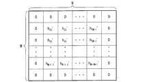
- FIG. 6 is a diagram illustrating each component of the prediction filter coefficient P corresponding to each pixel in the filter reference region R of M ⁇ N taps.
- the value of the prediction filter coefficient corresponding to each pixel in the peripheral part of the filter reference region R (that is, the prediction filter coefficient corresponding to the first group) is 0, and the peripheral part of the filter reference region R
- the values of the prediction filter coefficients corresponding to the other pixels are the values of the filter coefficients h ′ (i, j) as they are.
- the filter coefficient corresponding to each pixel in the periphery of the filter reference region R tends to be a value close to zero.
- the filter coefficient prediction unit 140 in the moving image decoding apparatus 1 performs the operation of this example, thereby calculating the prediction filter coefficient # 140 based on the filter coefficient residual # 13d generated in this way with a small code amount. Can be derived.
- prediction filter coefficient deriving unit 143 in this example may be configured to derive the prediction filter coefficient for the center pixel of the filter reference region R using Expression (6).
- the moving picture encoding apparatus 2 includes H.264 as a part thereof. H.264 / MPEG-4 AVC, and a decoding device including technology adopted in KTA software.
- FIG. 7 is a block diagram showing a configuration of the moving picture encoding apparatus 2.
- the moving image encoding device 2 includes a transform / quantization unit 21, a variable length encoding unit 22, an inverse quantization / inverse transform unit 23, a buffer memory 24, an intra predicted image generation unit 25, an inter prediction image generation unit 25, and an inter prediction image generation unit 25.
- a prediction image generation unit 26, a prediction scheme control unit 28, a motion vector redundancy reduction unit 29, an adder 31, a subtractor 32, a deblocking filter 50, and an adaptive filter 100 ′ are provided.
- the input image # 10 divided into macro blocks is input to the moving image encoding device 2.
- the moving image encoding device 2 performs an encoding process on the input image # 10 and outputs encoded data # 1.
- the transform / quantization unit 21 converts the difference image # 32 between the input image # 10 divided into macroblocks and a prediction image # 28a output from the prediction scheme control unit 28, which will be described later, into frequency components by DCT conversion. After conversion, the frequency component is quantized to generate quantized prediction residual data # 21.
- the quantization is an operation for associating the frequency component with an integer value.
- the DCT transform and quantization are performed in units of blocks obtained by dividing a macroblock.
- a macro block to be processed is referred to as a “target macro block”
- a block to be processed is referred to as a “target block”.
- the inverse quantization / inverse transform unit 23 decodes the quantized prediction residual data # 21 and generates a prediction residual # 23. Specifically, the inverse quantization / inverse transform unit 23 performs inverse quantization of the quantized prediction residual data # 21, that is, associates integer values constituting the quantized prediction residual data # 21 with frequency components. Then, inverse DCT transformation of the frequency component, that is, inverse transformation to the pixel component of the target macroblock based on the frequency component is performed to generate prediction residual # 23.
- the adder 31 adds the prediction residual # 23 and the prediction image # 28a to generate a decoded image # 31.
- the generated decoded image # 31 is supplied to the deblocking filter 50.
- the deblocking filter 50 performs a deblocking process on the block boundary or the macroblock boundary in the decoded image # 31.
- the image data subjected to the deblocking process is output as a deblocked image # 50.
- the deblocking filter 50 has the same configuration as the deblocking filter 50 included in the video decoding device 1.
- the adaptive filter 100 ′ performs filtering on the deblocked image # 50 and outputs output image data # 100 ′ to the buffer memory 24.
- the adaptive filter 100 ′ also outputs a filter coefficient residual # 102 that is a residual between the filter coefficient used for filtering and the predicted filter coefficient to the variable length coding unit 22.
- the adaptive filter 100 ′ is a variable-length encoding unit for filtering parameter information, which is information related to a parameter indicating an area to be filtered, a parameter indicating the number of taps for filtering, and a parameter for specifying on / off of filtering. 22 is output. Since the configuration of the adaptive filter 100 ′ will be described later, the description thereof is omitted here.
- the intra-predicted image generation unit 25 extracts the local decoded image # 24a (the already decoded region in the same frame as the target macroblock) from the output image data # 100 ′ stored in the buffer memory 24, and based on the local decoded image # 24a Intra-frame prediction is performed to generate intra-predicted image # 25.
- the inter prediction image generation unit 26 calculates and assigns a motion vector # 27 to the target block on the input image # 10 by using the reference image # 24b in which the entire frame has already been decoded and stored in the buffer memory 24. .
- the calculated motion vector # 27 is output to the inter prediction image generation unit 26 and the motion vector redundancy reduction unit 29 and is stored in the buffer memory 24.
- the inter predicted image generation unit 26 performs motion compensation on the reference image # 24b based on the motion vector # 27 for each block, and generates an inter predicted image # 26.
- the prediction method control unit 28 compares the intra prediction image # 25, the inter prediction image # 26, and the input image # 10 in units of macro blocks, and the intra prediction image # 25 or the inter prediction image # 26. Any one of them is selected and output as a predicted image # 28a. In addition, the prediction method control unit 28 outputs a prediction mode # 28b that is information indicating which one of the intra prediction image # 25 or the inter prediction image # 26 is selected. The predicted image # 28a is input to the subtracter 32.
- the prediction mode # 28b is stored in the buffer memory 24 and input to the variable length encoding unit 22.
- the motion vector redundancy reduction unit 29 assigns the motion vector # 27 to the target block in the inter predicted image generation unit 26, and then assigns the motion vector # 27c to the other block and stored in the buffer memory 24. Based on this, a prediction vector is calculated. In addition, the motion vector redundancy reduction unit 29 takes the difference between the prediction vector and the motion vector # 27, and generates a difference motion vector # 29. The generated difference motion vector # 29 is output to the variable length coding unit 22.
- variable length encoding unit 22 performs variable length encoding on the quantized prediction residual data # 21, the differential motion vector # 29, the prediction mode # 28b, the filter coefficient residual # 102, and the filter parameter information, Coded data # 1 is generated.
- the subtractor 32 takes the difference between the input image # 10 and the predicted image # 28a for the target macroblock, and outputs a difference image # 32.
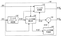
- FIG. 8 is a block diagram showing a configuration of the adaptive filter 100 ′.
- the adaptive filter 100 ′ includes a filter processing unit 110 ′, a filter parameter determination unit 120 ′, a filter coefficient derivation unit 130 ′, a filter coefficient prediction unit 140 ′, and a subtractor 102.
- the filter parameter determination unit 120 ′ based on the side information of the input image # 10, sets a parameter indicating the number of reference pixels for filtering (number of taps), a parameter group that specifies filtering on / off, and the like (hereinafter referred to as filter parameters).
- the filter parameter information # 120 ′ which is information including the filter parameter group, is output.
- the side information of the input image # 10 includes a prediction mode, a motion vector, a reference image index indicating a reference frame, a quantization parameter, and the like.
- the filter parameter group determination method does not limit the present invention.
- the filter parameter determination unit 120 ′ determines the block size of the blocks constituting the input image # 10 or the input image # 10.
- a configuration may be adopted in which the filter parameter group is determined according to the number of hierarchies when hierarchically divided by a quad-tree.
- the subtractor 102 generates and outputs a filter coefficient residual # 102 by taking the difference between the filter coefficient # 130 'and the prediction filter coefficient # 140'.
- the filter processing unit 110 ′ generates and outputs output image data # 100 ′ by filtering the deblocked image # 50 using the filter coefficient # 130 ′.
- the filtering process in the filter processing unit 110 ′ is almost the same as the filtering process in the filter processing unit 110 in the moving image decoding apparatus 1 described above.
- the filter processing unit 110 represents the pixel value S0 (x ′, y ′) at the coordinates (x ′, y ′) of the output image data # 100 ′ by the above equation (1), and the filter coefficient # It is calculated by taking a weighted linear sum with 130 ′ and adding an offset based on filter coefficient # 101.
- the filter coefficient h (i, j) in Expression (1) corresponds to the filter coefficient # 130'.
- the filter coefficient deriving unit 130 ′ derives the filter coefficient # 130 ′ using the input image # 10 and the deblocked image # 50 based on the filter parameter information # 120 ′ output from the filter parameter determining unit 120 ′. .
- the derived filter coefficient # 130 ′ is output to the filter coefficient prediction unit 140 ′, the subtractor 102, and the filter processing unit 110 ′.
- the filter coefficient deriving unit 130 ′ determines the value of the filter coefficient h (i, j) by, for example, the following expression (13), each pixel value of the input image # 10 and each pixel of the output image data # 100 ′. Derived so as to minimize the square error E3 with the value.
- S (x, y) represents the pixel value at the coordinates (x, y) of the input image # 10
- SI (x, y) represents the coordinates (x, y) of the deblocked image # 50.
- O represents an offset.
- the filter coefficient h (i, j) derived in this way (1 ⁇ i ⁇ M, 1 ⁇ j ⁇ N) is output as filter coefficient # 130 ′ from the filter coefficient deriving unit 130 ′, and the filter processing unit Used for filtering at 110 '.
- the filter coefficient prediction unit 140 ′ performs substantially the same operation as the filter coefficient prediction unit 140 included in the video decoding device 1. However, in the moving picture coding apparatus 2, the filter coefficient supplied to the filter coefficient prediction unit 140 ′ is the filter coefficient # 130 ′, and the prediction filter coefficient output from the filter coefficient prediction unit 140 ′ is the prediction filter coefficient. # 140 '.
- FIG. 9 is a block diagram showing the configuration of the filter coefficient prediction unit 140 '.
- the filter coefficient prediction unit 140 ' includes a filter coefficient storage unit 141', a weight coefficient calculation unit 142 ', and a prediction filter coefficient derivation unit 143'.
- the filter coefficient storage unit 141 ′ performs substantially the same operation as the filter coefficient storage unit 141 in the video decoding device 1. However, the filter coefficient stored in the filter coefficient storage unit 141 ′ includes the filter coefficient # 141 ′ already used in the filtering process for the encoded frame.
- the filter coefficient matrix that is stored in the filter coefficient storage unit 141 ′ and that is configured by the filter coefficient # 141 ′ that has already been used in the filtering process for the encoded frame is expressed as in Expression (2) already described. be able to.
- the filter coefficient h ′ (i, j) corresponds to the filter coefficient # 141 ′ already used in the filtering process for the encoded frame.
- the weight coefficient calculation unit 142 ′ calculates the weight coefficient a (i, j) by which each component h ′ (i, j) of the filter coefficient matrix H ′ is multiplied. To do. Since a specific example of the calculation processing of the weighting factor a (i, j) by the weighting factor calculating unit 142 ′ will be described later, the description thereof is omitted here.
- the prediction filter coefficient derivation unit 143 ′ Similar to the prediction filter coefficient derivation unit 143 in the video decoding device 1, the prediction filter coefficient derivation unit 143 ′ performs filtering processing on an encoded frame among the filter coefficients stored in the filter coefficient storage unit 141 ′. Based on the already used filter coefficient h ′ (i, j) and the weight coefficient a (i, j) calculated by the weight coefficient calculation unit 142 ′, the prediction filter coefficient p (i, j) is derived. . The derived prediction filter coefficient p (i, j) is output as prediction filter coefficient # 140 '.
- the prediction filter coefficient matrix P having the prediction filter coefficient p (i, j) as a component can be expressed, for example, as already described in Expression (5).
- the prediction filter coefficient deriving unit 143 ′ uses the filter for pixels other than the center of the filter reference region R for prediction filter coefficients corresponding to the center pixel of the filter reference region R among the prediction filter coefficients p (i, j). It is good also as a structure derived
- the prediction filter coefficient deriving unit 143 ′ derives the prediction filter coefficient p_center for the center pixel of the filter reference region R among the filter coefficients h (i, j) using the already-described expression (6). It is good also as a structure.
- the prediction accuracy of the prediction filter coefficient is increased by using the tendency that the sum of the filter coefficients h (i, j) in the filter reference region R is close to 1. It can be improved effectively.
- the sum of filter coefficients in the filter reference region R tends to be close to 1. Therefore, according to the above configuration, the code amount of the filter coefficient residual # 102 can be reduced.
- the variable length coding unit 22, the subtractor 102, and the filter coefficient prediction unit 140 ′ are filter coefficient # 130 supplied from the filter coefficient deriving unit 130 ′.
- a filter coefficient encoding apparatus that encodes a filter coefficient residual # 102 that is a residual between 'and a prediction filter coefficient # 140' predicted based on the filter coefficient # 130 'is configured. it can. Therefore, the moving picture coding apparatus 2 according to the present embodiment can also be expressed as a moving picture coding apparatus including such a filter coefficient coding apparatus.
- the filter coefficient prediction unit 140 'performs an operation corresponding to the calculation process of the prediction filter coefficient # 140 by the filter coefficient prediction unit 140 described in (Specific example 1-1).
- the weight coefficient calculation unit 142 ′ first divides the filter reference region R into a plurality of groups (subregions) from the center of the filter reference region R toward the periphery (see FIG. 5).
- the weighting factor calculation unit 142 sets the weighting factor a (i, j) for each group to a predetermined value.
- a predetermined value for example, a value determined in advance by the method of least squares may be used.
- FIG. 10 shows weighting factors a (i, j) corresponding to groups 1 to 4 constituting the filter reference region R shown in FIG. 5 by using four different sequences and four different quantization parameters. It is a graph which shows the result computed beforehand by applying the least squares method to the frame for 200 frames.
- the square error to be minimized in the least square method the square error E1 represented by the already described formula (10) was taken.
- the optimum weighting coefficient obtained by the least square method has a larger value in a region closer to the center of the filter reference region R. This is because the correlation between the frames of the filter coefficients becomes larger as the region is closer to the center of the filter reference region R.
- the weighting factor calculation unit 142 ′ sets the optimum weighting factor value for each group obtained in advance by the least square method or an approximate value thereof as the weighting factor for each pixel belonging to each group. .
- the weighting factor calculation unit 142 ′ multiplies 2, 4, 5, 6, and 8 for each group to round 4 for rounding.
- the weight coefficient # 142 may be calculated using integer arithmetic that adds 3 and shifts right by 3 bits.
- the weighting coefficient calculation unit 142 ′ outputs the weighting coefficient a_grG for each group set in this way as the weighting coefficient # 142 ′ to the prediction filter coefficient derivation unit 143 ′, and the prediction filter coefficient derivation unit 143 ′
- the prediction filter coefficient # 140 ′ is derived using the weight coefficient # 142 ′.
- the value of the weight coefficient a_gr5 for the group 5 may be determined according to the values of the weight coefficients a_gr1 to a_gr4, or a predetermined value (for example, 1) may be used.
- the prediction filter coefficient deriving unit 143 ′ may be configured to derive the prediction filter coefficient for the central pixel of the filter reference region R among the prediction filter coefficients # 140 ′ using the already-described formula (6). Good.
- the filter coefficient prediction unit 140 ′ divides the filter reference region R into a plurality of sub-regions, and derives a prediction filter coefficient # 140 ′ using the weighting factor set for each sub-region. Therefore, the code amount of the filter coefficient residual # 102 can be reduced as compared with the conventional method in which the filter reference region R is not divided.
- the weighting factor calculation unit 142 ′ stores the value of the weighting factor in a memory, so that the optimum weighting factor can be obtained without performing the weighting factor calculation process using the least square method. Therefore, it is possible to output an optimum weight coefficient while reducing the amount of calculation compared to the case where the least square method is used for each frame.
- the code amount of the filter coefficient residual # 102 can be reduced with a small amount of calculation.
- the weighting factor calculation unit 142 ′ performs grouping from the center of the filter reference region R of M ⁇ N taps toward the peripheral part, and the weighting factor for each group is determined by an optimal method obtained in advance by the least square method. It can be set as a structure which sets to a weighting coefficient or its approximate value.
- the method of dividing the filter reference region R by the weight coefficient calculating unit 142 ′ is not limited to the above example, and an optimal dividing method may be adopted according to the characteristics of the filter coefficient. For example, it is also preferable to divide the weight coefficient for each filter coefficient.
- the filter coefficient prediction unit 140 'performs an operation corresponding to the calculation process of the prediction filter coefficient # 140 by the filter coefficient prediction unit 140 described in (Specific example 1-2).
- the weight coefficient calculation unit 142 ′ first divides the filter reference region R into a plurality of groups from the center of the filter reference region R toward the peripheral part, as in (Specific example 1-1 ′).
- the weighting factor calculation unit 142 ′ first calculates the weighting factor a_grG ′ (s) for the region on the decoded frame and the region of the group G using the already encoded filter coefficients. To do.
- the index s in a_grG ′ (s) indicates that the frame is s frames before counting from the prediction target frame.
- the frame before s frames counted from the prediction target frame is referred to as a frame s.
- the weight coefficient calculation unit 142 ′ is referred to calculate the weight coefficient a_grG ′ (s) for the frame s and the predicted value of the filter coefficient h (i, j) (s) for the frame s. Using the filter coefficient h (i, j) (s_prev) and the filter coefficient h (i, j) (s) for the frame s, the calculation is performed according to the equation (7) already described.
- the weighting factor calculation unit 142 ′ calculates the weighting factor a_grG using the representative value of the calculated weighting factor a_grG ′ (s).
- the representative value for example, the median value of the weighting coefficient a_grG ′ (s) calculated for a plurality of frames can be used.
- the weighting factor calculation unit 142 calculates the weighting factor a_grG by the equation (8) already described.
- the weighting factor calculation unit 142 ′ is a weighting factor calculated for each frame from one frame before to F frames before counting from the prediction target frame, and the weighting factor a_grG ′ (1) for the group G Set the median value of a_grG ′ (F) to the weight coefficient a_grG.
- the specific value of F may be a predetermined value as in (Specific Example 1-2), or determined according to the position of the filter reference region R in the frame, for example. The value to be used may be used.
- the weighting coefficient used for the prediction of the filter coefficient h (i, j) (s) for the frame s may be used as it is.
- the weighting coefficient calculation unit 142 ′ outputs the weighting coefficient a_grG for each group set in this way as the weighting coefficient # 142 ′ to the prediction filter coefficient derivation unit 143 ′, and the prediction filter coefficient derivation unit 143 ′
- the prediction filter coefficient # 140 ′ is derived using the weight coefficient # 142 ′.
- the filter coefficient prediction unit 140 ′ can reduce the code amount of the filter coefficient residual # 102 by performing the operation as in this example.
- prediction filter coefficient deriving unit 143 may be configured to derive the prediction filter coefficient for the center pixel of the filter reference region R using Expression (6).
- the above-described operation by the weighting factor calculation unit 142 ′ is performed, for example, by including a memory in which the weighting factor calculation unit 142 stores a weighting factor that has already been calculated for each region on the decoded frame. It becomes possible.
- the filter coefficient prediction unit 140 'performs an operation corresponding to the calculation process of the prediction filter coefficient # 140 by the filter coefficient prediction unit 140 described in (Specific Example 1-3).
- the weighting factor calculation unit 142 ′ calculates the weighting factor for each group constituting the filter reference region R by using the average value as the representative value in the above-described (specific example 1-2 ′). .
- the weighting factor calculation unit 142 ′ calculates the weighting factor a_grG according to Expression (9).
- the weighting factor calculation unit 142 ′ is a weighting factor calculated for each frame from one frame before to F frames before counting from the prediction target frame, and the weighting factor a_grG ′ (1) for the group G
- the average value of .about.a_grG ′ (F) is set to the weighting coefficient a_grG.
- the filter coefficient prediction unit 140 ′ can reduce the code amount of the filter coefficient residual # 102 by performing the operation as in this example.
- the filter coefficient prediction unit 140 'performs an operation corresponding to the calculation process of the prediction filter coefficient # 140 by the filter coefficient prediction unit 140 described in (Specific Example 1-4).
- the weight coefficient calculation unit 142 ′ first divides the filter reference region R into a plurality of groups from the center of the filter reference region R toward the peripheral part, as in (Specific example 1-1 ′).
- the weighting factor calculation unit 142 calculates the weighting factor a (i, j) by the least square method.
- the weighting factor calculating unit 142 calculates the weighting factor a (i, j) so as to minimize the square error E1 represented by the already described formula (10).
- h (i, j) (t_prev) in the equation (10) is an encoded filter coefficient in this example, and is a prediction filter coefficient corresponding to the filter coefficient h (i, j) (t). It shall represent the filter coefficient referred for calculation.
- the specific calculation processing of the weighting factor a (i, j) by the weighting factor calculation unit 142 'in this example is the same as (Specific example 1-4).
- the weighting coefficient calculation unit 142 ′ calculates the weighting coefficient a_grG for each group by averaging the weighting coefficient a (i, j) calculated using the least square method for each group constituting the filter reference region. It is calculated and output to the prediction filter coefficient deriving unit 143 ′ as the weight coefficient # 142 ′.
- the prediction filter coefficient deriving unit 143 ' uses the weighting coefficient # 142' to derive the prediction filter coefficient # 140 '.
- the weight coefficient calculation unit 142 ′ calculates the weight coefficient for each group using the least square method, so that the code amount of the filter coefficient residual # 102 can be reduced.
- the weighting factor calculation unit 142 ′ calculates the weighting factor a (i, j) calculated using the least squares method for each group constituting the filter reference region. It is good also as a structure which calculates weighting coefficient a_grG with respect to each group by taking a value.
- the weighting factor calculation unit 142 ′ may be configured to calculate the weighting factor a_grG for each group by the least square method using Equation (11), as in (Specific Example 1-4).
- the prediction filter coefficient deriving unit 143 ' may be configured to derive the prediction filter coefficient for the center pixel of the filter reference region R using Expression (6).
- the filter coefficient prediction unit 140 'performs an operation corresponding to the calculation process of the prediction filter coefficient # 140 by the filter coefficient prediction unit 140 described in (Specific example 1-5).
- the weight coefficient calculation unit 142 ′ divides the filter reference region R into a first sub-region that is a peripheral portion of the filter reference region R and a second sub-region that is a region other than the first sub-region.
- the peripheral part of the filter reference region R is a region in the filter reference region R, which is in contact with the outer edge of the filter reference region R or in the vicinity of the outer edge of the filter reference region R (hereinafter referred to as “the reference region”). The same).
- the weighting factor calculation unit 142 sets the value of the weighting factor for the first subregion to 0, and sets the value of the weighting factor for the second subregion to 1.
- the weighting coefficient matrix A1 composed of the weighting coefficients a (i, j) calculated by the weighting coefficient calculating unit 142 in this way can be expressed as in Expression (12).
- a component having a value of 0 in the weighting coefficient matrix A1 represents a weighting factor for the first sub-region
- a component having a value of 1 represents a weighting factor for the second sub-region.
- each component of the prediction filter coefficient matrix P calculated by the prediction filter coefficient deriving unit 143 ′ becomes 0 for each pixel corresponding to the first group.
- the filter coefficient h ′ (i, j) is a value as it is (see FIG. 6).
- the filter coefficient corresponding to each pixel in the periphery of the filter reference region R tends to be a value close to zero.
- the amount of calculation related to calculation of the prediction filter coefficient can be reduced.
- the code amount of the filter coefficient residual # 101 can be reduced.
- the value of the filter coefficient corresponding to the peripheral pixels of the filter reference region R is 0.1.
- the filter coefficient h ′ (i, j) when the value of the filter coefficient corresponding to the peripheral pixel of the filter reference region R is ⁇ 0.1, the filter coefficient h ′ (i, j) If the filter coefficient residual is generated with the prediction filter coefficient as is, the value of the filter coefficient residual corresponding to the above pixel becomes 0.2, but this corresponds to the peripheral pixel of the filter reference region R as in this example.
- a filter coefficient residual is generated by setting the value of the prediction filter coefficient to be 0, the value of the filter coefficient residual corresponding to the pixel is 0.1.
- the code amount of the filter coefficient residual # 102 can be reduced.
- prediction filter coefficient deriving unit 143 in this example may be configured to derive the prediction filter coefficient for the center pixel of the filter reference region R using Expression (6).
- FIG. 11A shows a bit stream #BS for each slice of the encoded data # 1 generated by the video encoding device 2 and referred to by the video decoding device 1.
- the bitstream #BS includes filter parameter information FP, filter coefficient residual information RC, and macroblock information MB1 to MBN.
- the filter coefficient residual information RC is information including the filter coefficient residual # 102 generated in the video encoding device 2.
- Macroblock information MB1 to MBN is information used for decoding macroblocks existing in a slice. N represents the number of macroblocks present in the slice.
- the macroblock information includes a prediction mode, a motion vector, a reference image index, a quantization parameter, quantized prediction residual data, and the like.
- (B) of FIG. 11 shows an example of the configuration of the filter parameter information FP.
- the filter parameter information FP includes a parameter (number of taps) indicating the number of reference pixels for filtering and on / off designation information for designating filtering on / off.
- the filter parameter information FP may be configured to include weight coefficient information indicating the weight coefficient # 142 'calculated in the video encoding device 2.
- the filter coefficient residual includes the filter coefficient residual # 102 generated using the prediction filter coefficient # 140 'calculated by the process described in (Specific example 1-1').
- the weight coefficient information of the filter parameter information FP in the encoded data # 1 may be configured to include the weight coefficient # 142 ′ calculated in (Specific example 1-1 ′). Further, the weight coefficient information may include a parameter indicating the weight coefficient # 142 ′ instead of the weight coefficient # 142 ′ itself. For example, if the weighting factor of each group is a multiple of 1/8, such as 2/8, 4/8, 5/8, 6/8, 8/8, the numerator (2, 4, 5, 6, 8) and denominator (8) as parameters are included in the weight coefficient information. Further, when the weight coefficient # 142 ′ is recorded in advance in the memory included in the video decoding device 1, the weight coefficient information of the filter parameter information FP may not be included.
- the filter target region information may include information indicating how the filter reference region R is divided, for example, information indicating that the filter reference region R is grouped as illustrated in FIG. .
- the filter coefficient residual includes the filter coefficient residual # 102 generated using the prediction filter coefficient # 140 'calculated by the process described in (Specific example 1-2').
- the filter parameter information FP in the encoded data # 1 does not include weighting coefficient information. good.
- the filter target region information may include information indicating how the filter reference region R is divided, for example, information indicating that the filter reference region R is grouped as illustrated in FIG. .
- the filter coefficient residual includes the filter coefficient residual # 102 generated using the prediction filter coefficient # 140 'calculated by the processing described in (Specific Example 1-3').
- the filter parameter information FP in the encoded data # 1 does not include weighting coefficient information. good.
- the filter target region information may include information indicating how the filter reference region R is divided, for example, information indicating that the filter reference region R is grouped as illustrated in FIG. .
- the filter coefficient residual includes the filter coefficient residual # 102 generated using the prediction filter coefficient # 140 'calculated by the process described in (Specific Example 1-4').
- the filter parameter information FP in the encoded data # 1 does not include weighting coefficient information. good.
- the filter target region information may include information indicating how the filter reference region R is divided, for example, information indicating that the filter reference region R is grouped as illustrated in FIG. .
- the filter coefficient residual includes the filter coefficient residual # 102 generated using the prediction filter coefficient # 140 'calculated by the processing described in (Specific example 1-5').
- the filter parameter information FP in the encoded data # 1 does not include weighting coefficient information. good.
- the filter target region information may include information indicating how the filter reference region R is divided, for example, information indicating that the filter reference region R is grouped as illustrated in FIG. .
- FIG. 12 is a block diagram illustrating a configuration of the moving image decoding apparatus 3.
- the same blocks as those shown in FIG. 1 are denoted by the same reference numerals, and the description thereof is omitted.
- the moving image decoding apparatus 3 includes a variable length code decoding unit 51, a motion vector restoration unit 14, a buffer memory 15, an inter prediction image generation unit 16, an intra prediction image generation unit 17, and a prediction method determination unit 18. , An inverse quantization / inverse transform unit 19, an adder 20, a deblocking filter 50, and an adaptive filter 200.
- the video decoding device 3 receives the encoded data # 5 and outputs a decoded image # 6.
- variable-length code decoding unit 51 performs variable-length decoding on the encoded data # 5, performs differential motion vector # 13a, side information # 13b, quantized prediction residual data # 13c, filter coefficient residual # 13d, filter parameter information # 13e and flag # 51 indicating the filter coefficient calculation method are output.
- the adaptive filter 200 calculates a filter coefficient based on the filter coefficient residual # 13d according to the filter coefficient calculation method indicated by the flag # 51 decoded from the encoded data # 5, and applies the filter coefficient to the deblocked image # 50.
- Output image data # 200 is generated by performing filtering using.
- the output image data # 200 is supplied to the buffer memory 15.
- the filtering process in adaptive filter 200 is performed based on side information # 13b decoded from encoded data # 5 and parameters included in filter parameter information # 13e.
- FIG. 13 is a block diagram showing the configuration of the adaptive filter 200.
- the same reference numerals are assigned to the same blocks as those shown in FIG. 2, and the description thereof is omitted.
- the adaptive filter 200 includes a filter processing unit 110, a filter coefficient prediction unit 210, and an adder 202.
- the adder 202 generates the filter coefficient # 202 by adding the filter coefficient residual # 13d decoded from the encoded data # 5 and the prediction filter coefficient # 210 output from the filter coefficient prediction unit 210, Output.
- the filter coefficient prediction unit 210 follows the method indicated by the flag # 51 indicating the filter coefficient calculation method, and based on the filter coefficient already used in the filtering process for the decoded frame of the filter coefficient # 202, the prediction filter coefficient # 210 is calculated. Prediction filter coefficient # 210 is output to adder 202.
- FIG. 14 is a block diagram illustrating a configuration of the filter coefficient prediction unit 210.
- the same blocks as those shown in FIG. 4 are denoted by the same reference numerals, and the description thereof is omitted.
- the filter coefficient prediction unit 210 includes a filter coefficient storage unit 141, a weight coefficient calculation unit 142, and a prediction filter coefficient derivation unit 211.
- the filter coefficient prediction unit 210 outputs a prediction filter coefficient # 210 similar to the prediction filter coefficient # 140 described in (Specific example 1-1) to (Specific example 1-5) according to the flag # 51, or Alternatively, the filter coefficient # 141 already used in the filtering process for the decoded frame is output as the prediction filter coefficient # 210.
- the prediction filter coefficient derivation unit 211 included in the filter coefficient prediction unit 210 is calculated by the decoded filter coefficient # 141 and the weighting coefficient calculation unit 142. Based on the weighting coefficient # 142, each component of the prediction filter coefficient matrix P expressed by Expression (5) is derived and output as the prediction filter coefficient # 210.
- the calculation method of the weighting factor in the weighting factor calculation unit 142 any one of (Specific Example 1-1) to (Specific Example 1-5) described above may be used.
- the prediction filter coefficient deriving unit 211 outputs the decoded filter coefficient # 141 as the prediction filter coefficient # 210.
- the filter coefficient prediction unit 210 outputs the decoded filter coefficient # 141 as the prediction filter coefficient # 210 according to the flag # 51, or individually calculates for each group in the filter reference region R.
- the filter coefficient derived using the weighted coefficient is output as prediction filter coefficient # 210.
- the filter coefficient prediction unit 210 can decode the encoded data # 5 including the filter coefficient residual # 13d with a smaller code amount by performing such an operation.
- the filter coefficient prediction unit 210 outputs the decoded filter coefficient # 141 as the prediction filter coefficient # 210 without referring to the flag # 51, or is calculated individually for each group in the filter reference region R
- the filter coefficient derived using the weighting coefficient may be output as the prediction filter coefficient # 210.
- the weighting factor calculation unit 142 calculates the weighting factor # 142 by the method described in (Specific Example 1-2) of the first embodiment for each group constituting the 9 ⁇ 9 tap filter reference region
- the prediction filter is used in accordance with the same method as that shown in (Specific example 1-2) of the first embodiment using the weight coefficient a_grG.
- the coefficient # 210 may be derived, and if not, the decoded filter coefficient # 141 may be output as the prediction filter coefficient # 210.
- the weight coefficient # 142 calculated by the weight coefficient calculation unit 142 represents the correlation between frames.
- the region to which the smaller weight coefficient # 142 is assigned has a lower correlation between the filter coefficients in that region.
- the moving picture coding apparatus having a configuration corresponding to the above configuration, it is possible to more effectively reduce the code amount of the filter coefficient residual for the region where the correlation between the filter coefficient frames is lower. Moreover, according to said structure, the encoded data produced
- variable-length code decoding unit 51, the adder 202, and the filter coefficient prediction unit 210 are filter coefficient decoding devices that decode the filter coefficient # 202 based on the filter coefficient residual # 13d. It can be understood that it is composed.
- FIG. 15 is a block diagram illustrating a configuration of the moving image encoding device 4.
- the same blocks as those shown in FIG. 7 are denoted by the same reference numerals, and the description thereof is omitted.
- the moving image encoding device 4 includes a transform / quantization unit 21, an inverse quantization / inverse transform unit 23, a buffer memory 24, an intra predicted image generation unit 25, an inter predicted image generation unit 26, and a prediction.
- a system control unit 28, a motion vector redundancy reduction unit 29, an adder 31, a subtractor 32, a deblocking filter 50, a variable length coding unit 41, and an adaptive filter 200 ′ are provided.
- the input image # 4 divided into block images composed of a plurality of adjacent pixels is input to the moving image encoding device 4.
- the moving image encoding device 4 performs an encoding process on the input image # 4 and outputs encoded data # 5.
- variable-length encoding unit 41 applies the quantized prediction residual data # 21, the difference motion vector # 29, the prediction mode # 28b, the flag # 220 indicating the filter coefficient prediction method, and the filter coefficient residual # 102. Variable length encoding is performed to generate encoded data # 5.
- the adaptive filter 200 ′ generates output image data # 200 ′ by filtering the deblocked image # 50 and outputs the output image data # 200 ′ to the buffer memory 24.
- the adaptive filter 200 ′ also outputs a filter coefficient residual # 102 that is a residual between the filter coefficient used for filtering and the predicted filter coefficient to the variable length coding unit 41.
- the adaptive filter 200 ′ also outputs a flag # 220 indicating the filter coefficient prediction method to the variable length coding unit 41.
- FIG. 16A shows a first configuration example of the adaptive filter 200 ′.
- the adaptive filter 200 ′ outputs the prediction filter coefficient selected according to the value of the weighting coefficient calculated by the filter coefficient prediction unit 210 ′.
- the adaptive filter 200 ′ includes a filter processing unit 110 ′, a filter parameter determination unit 120 ′, a filter coefficient derivation unit 130 ′, a filter coefficient prediction unit 210 ′, a subtractor 201a, and A prediction means selection unit 220a is provided.
- the subtractor 201a generates a filter coefficient residual # 102 by taking the difference between the filter coefficient # 130 'and the prediction filter coefficient # 210', and outputs the filter coefficient residual # 102 to the variable length coding unit 41.
- FIG. 17 is a block diagram illustrating a configuration of the filter coefficient prediction unit 210 ′.
- the same blocks as those shown in FIG. 9 are denoted by the same reference numerals, and the description thereof is omitted.
- the filter coefficient prediction unit 210 ′ includes a filter coefficient storage unit 141 ′, a weight coefficient calculation unit 142 ′, and a prediction filter coefficient derivation unit 211 ′.
- weighting coefficient # 142 'calculated by the weighting coefficient calculation unit 142' in the filter coefficient prediction unit 210 ' is also supplied to the prediction means selection unit 220a.
- the prediction filter coefficient deriving unit 211 ′ is configured according to the value of the flag # 220 supplied from the prediction unit selection unit 220a (specific example 1). -1 ′) to (prediction example 1-5 ′) in which the prediction filter coefficient # 210 ′ similar to the prediction filter coefficient # 140 ′ described above is output, or in the filtering process for the encoded frame
- the filter coefficient # 141 ′ already used is output as the prediction filter coefficient # 210 ′.
- the prediction means selection unit 220a outputs the flag # 220 depending on whether the value of the weight coefficient # 142 ′ is equal to or greater than a predetermined value.
- the weighting factor calculating unit 142 ′ calculates the weighting factor # 142 ′ by the method described in the first embodiment (specific example 1-2 ′) for each group constituting the 9 ⁇ 9 tap filter reference region.
- a flag # 220 indicating that a prediction filter coefficient is derived using the weight coefficient a_grG is output.
- the prediction means selection unit 220a uses the filter coefficient # 141 ′ already used in the filtering process for the encoded frame. A flag # 220 indicating output is output.
- any one of groups 1 to 4 may be taken.
- an average value of the weight coefficients a_gr1 to a_gr4 for each group may be used.
- the flag # 220 is output to the variable length coding unit 41 and is referred to by the prediction filter coefficient deriving unit 211.
- the weighting coefficient # 142 'calculated by the weighting coefficient calculation unit 142' represents a correlation between frames.
- the region to which the smaller weight coefficient # 142 'is assigned has a lower correlation between the filter coefficient frames in the region.
- the filter coefficient prediction unit 210 ′ derives the prediction filter coefficient # 210 ′ using the weighting coefficient # 142 ′, so that the filter coefficient residual # 102 for the region where the correlation between the frames of the filter coefficient is lower is obtained. Can be more effectively reduced. For regions where the correlation between the filter coefficient frames is higher, the calculation amount can be reduced by outputting the prediction filter coefficient # 210 'without using the weighting coefficient # 142'.
- the filter coefficient prediction unit 210 can effectively reduce the code amount of the filter coefficient residual # 102 while reducing the calculation amount.
- the weight coefficient calculation unit 142 ′ uses the weight coefficient # 142 by the method described in (Specific example 1-1 ′) to (Specific example 1-5 ′) of the first embodiment. It can be applied to the case where 'is calculated.
- the moving picture decoding apparatus that decodes the encoded data # 5 generated by the present configuration example sets the weight coefficient value calculated by the configuration corresponding to the weight coefficient calculation unit 142 ′ to the predetermined threshold th. By comparing the decoded filter coefficients with the predicted filter coefficients without referring to the flag # 220, or the weight coefficients calculated individually for each group in the filter reference region R. It is also possible to perform decoding processing using the filter coefficient derived by using the prediction filter coefficient.
- the prediction means selection unit 220a may be configured not to supply the flag # 220 to the variable length coding unit 41.
- FIG. 16B shows a second configuration example of the adaptive filter 200 ′.
- the adaptive filter 200 ′ is replaced with the prediction means selection section 220b described in (Configuration example 1 of the adaptive filter 200 ′), instead of the prediction means selection section 220b. It has.
- the prediction filter coefficient deriving unit 211 in this example uses the same prediction filter coefficient as the prediction filter coefficient # 140 ′ described in any one of (Specific example 1-1 ′) to (Specific example 1-5 ′), and performs encoding.
- the filter coefficient # 141 ′ already used in the filtering process for the already-completed frame is output as the prediction filter coefficient # 210 ′.
- the subtractor 201b generates a filter coefficient residual # 201b by taking the difference between the filter coefficient # 130 'and the prediction filter coefficient # 210' and outputs it to the prediction means selection unit 220b.
- the filter coefficient residual # 201b is already used in the filtering process for the filter coefficient residual # RC1 calculated using the prediction filter coefficient derived using the weighting coefficient # 142 ′ and the encoded frame.
- the filter coefficient residual # RC2 calculated using the obtained filter coefficient.
- the prediction means selection unit 220b compares the filter coefficient residual # RC1 with the filter coefficient residual # RC2, and outputs a smaller filter coefficient residual as the filter coefficient residual # 102.
- the input to the predictor selection unit 220b is used as the code amount of the filter coefficient residual, the two are compared, and the filter coefficient residual corresponding to the smaller code amount is set as the filter coefficient residual # 102. It may be configured to output.
- the prediction means selection unit 220b when outputting the filter coefficient residual # RC1, the prediction means selection unit 220b outputs a flag # 220 indicating that the prediction filter coefficient is derived using the weight coefficient # 142 ′, and the filter coefficient residual # RC1.
- a flag # 220 indicating that the prediction filter coefficient is calculated using the filter coefficient already used in the filtering process for the encoded frame is output.
- the adaptive filter 200 ′ can output the filter coefficient residual # 102 with a smaller code amount.
- variable-length encoding unit 41, the subtractor 201a (or subtractor 201b), and the filter coefficient prediction unit 210 ′ are filter coefficient encoding devices that encode the filter coefficient # 130 ′. It can be understood that it is composed.
- the data structure of the encoded data # 5 is almost the same as the data structure of the encoded data # 1 already described with reference to (a) to (b) of FIG. 11, but differs in the following points.
- the filter parameter information FP in the encoded data # 5 has a prediction filter coefficient derived using a weighting coefficient or filtering for an encoded frame A flag indicating whether the calculation has been performed using the filter coefficient already used in the processing is included. Further, the flag is included in the filter parameter information FP in the encoded data # 5.
- the video decoding device 3 that decodes the encoded data # 5 can derive the prediction filter coefficient by using the same method as that used in the video encoding device 4 by referring to the flag. Therefore, the moving picture decoding apparatus 3 that decodes the encoded data # 5 can decode the encoded data # 5 including the filter coefficient residual # 102 with a smaller code amount by referring to the flag.
- the encoded data # 5 includes the weight coefficient information. It can be set as the structure which does not contain.
- the code amount of the encoded data # 5 can be further reduced.
- the filter coefficient residual included in the encoded data # 5 corresponds to the filter coefficient residual derived using the filter coefficient already used in the filtering process for the encoded frame.
- the filter coefficient of the peripheral part (filter coefficient multiplied by the pixel value of the peripheral part of the input image) is a frame compared with the filter coefficient of central part (the filter coefficient multiplied by the pixel value of the central part of the input image).
- the correlation was small. Even if predictive encoding is performed, the encoding efficiency does not increase as expected, or the predictive encoding is rather deteriorated. This is also considered to be because predictive coding was performed in the same manner as the filter coefficient at the center of the high correlation between frames.
- the present invention has been made based on this finding.
- the filter coefficient encoding apparatus encodes a difference between a filter coefficient of a target filter acting on a target image and a predicted value of the filter coefficient.
- a prediction value generating means for generating the predicted value by multiplying each filter coefficient of the reference filter acting on the reference image by a weighting coefficient.
- the weighting factor to be multiplied is configured to be closer to 0 than the weighting factor to be multiplied by the filter coefficient at the center.
- the predicted value of the filter coefficient h of the target filter is generated by multiplying the filter coefficient h ′ of the reference filter by the weight coefficient a, and the difference h ⁇ between the filter coefficient h of the target filter and the predicted value ah ′.
- ah ′ is encoded.
- the weighting coefficient a (peripheral part) multiplied by the peripheral coefficient h ′ having a low inter-frame correlation is closer to 0 than the weighting coefficient a (center part) multiplying the peripheral coefficient h ′ having a high inter-frame correlation. I am doing so. For this reason, it is possible to effectively avoid a situation in which the coding efficiency of predictive coding decreases due to
- the filter coefficient encoding apparatus further includes storage means for storing the weight coefficient, and the predicted value generation means receives a weight coefficient multiplied by the filter coefficient of the target filter in the storage means. It is preferably configured to be the median value of the accumulated weight coefficients.
- the weight coefficient multiplied by each filter coefficient of the reference filter has a correlation between images. That is, the weighting coefficient used for generating the predicted value of the encoded filter coefficient tends to be an appropriate value for deriving the predicted value for the filter coefficient of the target filter.
- the filter coefficient encoding device further includes storage means for storing the weight coefficient, and the prediction value generation means multiplies the filter coefficient of the target filter by a weight coefficient.
- the prediction value generation means multiplies the filter coefficient of the target filter by a weight coefficient.
- the weighting factor accumulated in the accumulating unit since the median value of the weighting factors accumulated in the accumulating unit is used, the weighting factor that is significantly different from other weighting factors in the weighting factor accumulated in the accumulating unit. Even if a coefficient is included, a filter coefficient residual that is hardly affected by such a weight coefficient can be encoded.
- the filter coefficient encoding apparatus further includes storage means for storing the weight coefficient, and the predicted value generation means receives a weight coefficient multiplied by the filter coefficient of the target filter in the storage means. It is preferable to be configured to be an average value of the accumulated weight coefficients.
- the weight coefficient multiplied by each filter coefficient of the reference filter has a correlation between images. That is, the weighting coefficient used for generating the predicted value of the encoded filter coefficient tends to be an appropriate value for deriving the predicted value for the filter coefficient of the target filter.
- the filter coefficient encoding device further includes storage means for storing the weight coefficient, and the prediction value generation means multiplies the filter coefficient of the target filter by a weight coefficient.
- the prediction value generation means multiplies the filter coefficient of the target filter by a weight coefficient.
- the target filter since the average value of the weighting factors accumulated in the accumulating unit is used, even if the variation in the weighting factors accumulated in the accumulating unit is large, the target filter It is possible to generate appropriate prediction values for the filter coefficients.
- the filter coefficient encoding device sequentially encodes the filter coefficients of the target filter acting on the target image while switching between the target image and the reference image.
- a weighting factor setting that sets a common weighting factor that minimizes the sum of squares of differences between the filter coefficient of each reference filter and a common weighting factor to a weighting factor that multiplies the filter coefficient of the current reference filter
- Preferably further means are provided.
- the predicted value generation means subtracts the predicted value for the filter coefficient to be multiplied by the center pixel of the input image from the predetermined value by subtracting the sum of the other filter coefficients. It is preferable to calculate.
- the sum of filter coefficients before quantization tends to be close to 1.
- the sum of the filter coefficients after quantization tends to be close to the inverse of the quantization step.
- the prediction value for the filter coefficient to be multiplied by the center pixel of the input image can be calculated by subtracting the sum of the other filter coefficients from the predetermined value. There is a further effect that the amount can be more effectively reduced.
- Another filter coefficient encoding apparatus is a filter coefficient encoding apparatus that encodes a residual of a filter coefficient of a target filter acting on a target image with a predicted value for the filter coefficient.
- 1 is a first predicted value generation means for generating a first predicted value by multiplying each filter coefficient of the reference filter acting on the filter coefficient of the peripheral part, and the weighting coefficient to be multiplied by the filter coefficient of the peripheral part is the filter of the central part
- a first prediction value generating means configured to be smaller than a weighting coefficient to be multiplied by the coefficient; a second prediction value generating means for setting each filter coefficient of the reference filter to a second prediction value; and the weight
- the serial second predicted value is characterized by comprising a prediction value setting means for setting to the predicted value.
- the filter coefficient itself of the reference filter can be used as the predicted value, so that the amount of calculation required to decode the filter coefficient residual is reduced. There is an effect that can be.
- Another filter coefficient encoding apparatus is a filter coefficient encoding apparatus that encodes a residual of a filter coefficient of a target filter acting on a target image with a predicted value for the filter coefficient.
- 1 is a first predicted value generation means for generating a first predicted value by multiplying each filter coefficient of the reference filter acting on the filter coefficient of the peripheral part, and the weighting coefficient to be multiplied by the filter coefficient of the peripheral part is the filter of the central part
- a first prediction value generation unit configured to be smaller than a weighting factor to be multiplied by the coefficient
- a second prediction value generation unit that sets each filter coefficient of the reference filter to a second prediction value
- the first Prediction value setting means for setting one of the predicted values or the second predicted value having a smaller residual with the filter coefficient as the predicted value. It is characterized.
- the residual of the filter coefficient generated by using the first predicted value or the second predicted value having a smaller residual with the filter coefficient as the predicted value is encoded. Therefore, there is an effect that the code amount of the filter coefficient residual can be further reduced.
- the moving picture coding apparatus includes the filter coefficient coding apparatus, and performs filtering using the filter coefficient of the target filter on a locally decoded image.
- the above moving picture coding apparatus has the same effects as the filter coefficient coding apparatus.
- the filter coefficient decoding apparatus restores the filter coefficient of the target filter acting on the target image by adding a prediction value to the filter coefficient residual obtained by decoding the encoded data.
- the coefficient decoding apparatus includes a predicted value generating unit that generates the predicted value by multiplying each filter coefficient of the reference filter that acts on the reference image by a weighting coefficient, and the predicted value generating unit includes a filter coefficient in a peripheral portion.
- the weighting factor to be multiplied by is configured to be closer to 0 than the weighting factor to be multiplied by the filter coefficient at the center.
- the filter coefficient encoding device having a configuration corresponding to the above configuration generates a prediction value of the filter coefficient h of the target filter by multiplying the filter coefficient h ′ of the reference filter by the weight coefficient a, and the filter coefficient of the target filter
- the difference h ⁇ ah ′ between h and the predicted value ah ′ can be encoded, and the weight coefficient a (peripheral part) multiplied by the peripheral coefficient h ′ with low inter-frame correlation is represented as the peripheral part with high inter-frame correlation. It is possible to make it closer to 0 than the weighting coefficient a (center part) multiplied by the coefficient h ′. For this reason, it is possible to effectively avoid a situation in which the coding efficiency of predictive coding decreases due to
- the filter coefficient decoding apparatus having the above-described configuration can decode the encoded data with a small code amount generated as described above.
- the filter coefficient decoding apparatus further comprises storage means for storing the weight coefficient, and the prediction value generation means stores a weight coefficient to be multiplied by the filter coefficient of the target filter in the storage means. It is preferable that the weight value is set to be the median value.
- the weight coefficient multiplied by each filter coefficient of the reference filter has a correlation between images. That is, the weighting coefficient used for generating the predicted value of the decoded filter coefficient tends to be an appropriate value for deriving the predicted value for the filter coefficient of the target filter.
- the filter coefficient encoding device further includes storage means for storing the weight coefficient, and the predicted value generation means is a weight multiplied by the filter coefficient of the target filter. Since the coefficient is configured to be the median value of the weighting coefficients stored in the storage unit, the code amount of the filter coefficient residual can be more effectively reduced.
- the filter coefficient decoding apparatus having the above configuration has an effect of being able to decode encoded data with a small code amount generated as described above.
- the weighting factor accumulated in the accumulating unit since the median value of the weighting factors accumulated in the accumulating unit is used, the weighting factor that is significantly different from other weighting factors in the weighting factor accumulated in the accumulating unit. Even if the coefficient is included, the residual of the filter coefficient that is hardly affected by such a weighting coefficient can be decoded.
- the filter coefficient decoding apparatus further comprises storage means for storing the weight coefficient, and the prediction value generation means stores a weight coefficient to be multiplied by the filter coefficient of the target filter in the storage means. It is preferable that the average value of the weighted coefficients is set.
- the weight coefficient multiplied by each filter coefficient of the reference filter has a correlation between images. That is, the weighting coefficient used for generating the predicted value of the decoded filter coefficient tends to be an appropriate value for deriving the predicted value for the filter coefficient of the target filter.
- the filter coefficient encoding device further includes storage means for storing the weight coefficient, and the predicted value generation means is a weight multiplied by the filter coefficient of the target filter. Since the coefficient is configured to be the average value of the weighting coefficients stored in the storage unit, the code amount of the filter coefficient residual can be more effectively reduced.
- the filter coefficient decoding apparatus having the above configuration has an effect of being able to decode encoded data with a small code amount generated as described above.
- the target filter since the average value of the weighting factors accumulated in the accumulating unit is used, even if the variation in the weighting factors accumulated in the accumulating unit is large, the target filter It is possible to generate appropriate prediction values for the filter coefficients.
- the filter coefficient decoding device sequentially encodes the filter coefficients of the target filter acting on the target image while switching between the target image and the reference image.
- Weighting factor setting means for setting a common weighting factor that minimizes the sum of squares of differences between the filter coefficient of each reference filter and a common weighting factor to a weighting factor that multiplies the filter coefficient of the current reference filter It is preferable to further comprise.
- the predicted value generation means calculates a predicted value for the filter coefficient to be multiplied by the center pixel of the input image by subtracting the sum of other filter coefficients from a predetermined value. It is preferable to do.
- the sum of filter coefficients before quantization tends to be close to 1.
- the sum of the filter coefficients after quantization tends to be close to the inverse of the quantization step.
- the predicted value for the filter coefficient to be multiplied by the center pixel of the input image is calculated by subtracting the sum of the other filter coefficients from the predetermined value. Therefore, the code amount of the filter coefficient residual can be reduced more effectively.
- the filter coefficient decoding apparatus having the above configuration has an effect of being able to decode encoded data with a small code amount generated as described above.
- the predetermined value is, as described above, (1) whether or not the filter coefficient is quantized, and (2) if the filter coefficient is quantized. It can be determined according to the size of the quantization step.
- Another filter coefficient decoding apparatus adds a predicted value to a filter coefficient residual obtained by decoding encoded data, with a filter coefficient of the target filter acting on the target image.
- a first prediction value generation means for generating a first prediction value by multiplying each filter coefficient of a reference filter acting on a reference image by a weighting coefficient, the filter coefficient of a peripheral portion
- a first prediction value generating means configured to make the weighting coefficient to be multiplied by a weighting coefficient to be multiplied by the filter coefficient in the central portion, and a second prediction value for setting each filter coefficient of the reference filter to a second prediction value.
- the first predicted value is set as the predicted value, and the weighted coefficient If the value is above a predetermined value or more, and the second predicted value and characterized by comprising a prediction value setting means for setting to the predicted value.
- the filter coefficient encoding device having a configuration corresponding to the above configuration, when the value of the weighting factor is smaller than a predetermined value, the weighting factor is calculated as the predicted value. If the weight coefficient value is equal to or greater than a predetermined value, the filter coefficient of the reference filter itself can be used as the predicted value, so that the filter coefficient residual is decoded. It is possible to reduce the amount of calculation required to do.
- the filter coefficient decoding apparatus having the above configuration has an effect of being able to decode encoded data with a small code amount generated as described above.
- Another filter coefficient decoding apparatus adds a predicted value to a filter coefficient residual obtained by decoding encoded data, with a filter coefficient of the target filter acting on the target image.
- a first prediction value generation means for generating a first prediction value by multiplying each filter coefficient of a reference filter acting on a reference image by a weighting coefficient, the filter coefficient of a peripheral portion
- a first prediction value generating means configured to make the weighting coefficient to be multiplied by a weighting coefficient to be multiplied by the filter coefficient in the central portion, and a second prediction value for setting each filter coefficient of the reference filter to a second prediction value.
- the two predicted value generation means and the first predicted value or the second predicted value the one having a smaller residual with the filter coefficient is the predicted value. It is characterized by comprising a prediction value setting means for setting.
- the first predicted value or the second predicted value that has a smaller residual with the filter coefficient is the predicted value. Since the residual of the filter coefficient generated as can be encoded, the code amount of the residual of the filter coefficient can be further reduced.
- the filter coefficient decoding apparatus having the above configuration has an effect of being able to decode encoded data with a small code amount generated as described above.
- the moving picture decoding apparatus includes the filter coefficient decoding apparatus, and performs filtering using the filter coefficient of the target filter on the local decoded image.
- the above moving picture decoding apparatus has the same effects as the filter coefficient decoding apparatus.
- the data structure of the encoded data according to the present invention is encoded data data obtained by encoding a residual of a filter coefficient of a target filter acting on a target image with a predicted value for the filter coefficient.
- the structure includes weight coefficient information that specifies weight coefficients to be multiplied by each filter coefficient of the reference filter that acts on the reference image, and multiplies the peripheral filter coefficients. It is characterized in that the weighting factor is smaller than the weighting factor by which the filter coefficient at the center is multiplied.
- the filter coefficient in the peripheral part tends to have a smaller correlation between frames than the filter coefficient in the central part.
- the code amount of the filter coefficient residual can be reduced by making the weight coefficient multiplied by the filter coefficient in the peripheral part smaller than the weight coefficient multiplied by the filter coefficient in the central part.
- the encoded data having the above configuration is encoded data with a small code amount including such a weight coefficient.
- the filter coefficient decoding apparatus that decodes the encoded data having the above configuration can decode the encoded data with a small code amount of the filter coefficient residual by referring to the weight coefficient information.
- the present invention is suitably applied to a moving image encoding device that encodes a moving image and generates encoded data, and a moving image decoding device that decodes encoded data generated using such a moving image encoding device.
- a moving image decoding device that decodes encoded data generated using such a moving image encoding device.
- it can be suitably applied to, for example, a broadcast receiving terminal and an HDD recorder.
- 1 moving picture decoding apparatus 100 adaptive filter 110 filter processing unit 140 filter coefficient prediction unit (prediction value generation means) 141 Filter coefficient storage unit 142 Weight coefficient calculation unit 143 Prediction filter coefficient derivation unit 2 Video encoding device 100 ′ Adaptive filter 110 ′ Filter processing unit 120 ′ Filter parameter determination unit 130 ′ Filter coefficient derivation unit 140 ′ Filter coefficient prediction unit ( Predicted value generation means) 141 ′ filter coefficient storage section 142 ′ weight coefficient calculation section 143 ′ prediction filter coefficient derivation section
Landscapes
- Engineering & Computer Science (AREA)
- Multimedia (AREA)
- Signal Processing (AREA)
- Compression Or Coding Systems Of Tv Signals (AREA)
Abstract
La présente invention se rapporte à un dispositif de codage de coefficient de filtrage qui code la valeur résiduelle des coefficients de filtrage d'un filtre d'objet qui agit sur une image d'objet et des valeurs prédites pour lesdits coefficients de filtrage. Le dispositif de codage de coefficient de filtrage selon l'invention comprend un module de prédiction de coefficient de filtrage (140') qui génère les valeurs prédites susmentionnées en multipliant des facteurs de pondération par chaque coefficient de filtrage d'un filtre de référence qui agit sur une image de référence ; et le module de prédiction de coefficient de filtrage unité (140') est configuré de façon à ce que les facteurs de pondération multipliés par les coefficients de filtrage dans la section de périphérie soient moins élevés que les facteurs de pondération multipliés par des coefficients de filtrage dans la section centrale.
Priority Applications (1)
| Application Number | Priority Date | Filing Date | Title |
|---|---|---|---|
| JP2012501739A JPWO2011105231A1 (ja) | 2010-02-26 | 2011-02-10 | フィルタ係数符号化装置、フィルタ係数復号装置、動画像符号化装置、動画像復号装置、および、データ構造 |
Applications Claiming Priority (2)
| Application Number | Priority Date | Filing Date | Title |
|---|---|---|---|
| JP2010-043169 | 2010-02-26 | ||
| JP2010043169 | 2010-02-26 |
Publications (1)
| Publication Number | Publication Date |
|---|---|
| WO2011105231A1 true WO2011105231A1 (fr) | 2011-09-01 |
Family
ID=44506645
Family Applications (1)
| Application Number | Title | Priority Date | Filing Date |
|---|---|---|---|
| PCT/JP2011/052923 Ceased WO2011105231A1 (fr) | 2010-02-26 | 2011-02-10 | Dispositif de codage de coefficient de filtrage, dispositif de décodage de coefficient de filtrage, dispositif de codage vidéo, dispositif de décodage vidéo, et structure de données |
Country Status (2)
| Country | Link |
|---|---|
| JP (1) | JPWO2011105231A1 (fr) |
| WO (1) | WO2011105231A1 (fr) |
Cited By (4)
| Publication number | Priority date | Publication date | Assignee | Title |
|---|---|---|---|---|
| WO2012137890A1 (fr) * | 2011-04-05 | 2012-10-11 | シャープ株式会社 | Appareil de filtrage d'image, appareil décodeur, appareil codeur et structure de données |
| JP2014532375A (ja) * | 2011-10-13 | 2014-12-04 | クゥアルコム・インコーポレイテッドQualcomm Incorporated | ビデオコーディングにおいて適応ループフィルタとマージされたサンプル適応オフセット |
| WO2019111720A1 (fr) * | 2017-12-06 | 2019-06-13 | ソニー株式会社 | Dispositif de codage, procédé de codage, dispositif de décodage, et procédé de décodage |
| WO2019198519A1 (fr) * | 2018-04-11 | 2019-10-17 | ソニー株式会社 | Dispositif de traitement de données et procédé de traitement de données |
Citations (5)
| Publication number | Priority date | Publication date | Assignee | Title |
|---|---|---|---|---|
| JPH08163408A (ja) * | 1994-12-02 | 1996-06-21 | Sony Corp | ノイズ検出回路、ノイズ除去回路及び輪郭強調回路 |
| JP2003529115A (ja) * | 1999-02-17 | 2003-09-30 | サン マイクロシステムズ,インコーポレイティッド | スーパサンプリング・サンプル・バッファを有し、サンプル位置情報を効果的に記憶するグラフィックス・システム |
| JP2006135376A (ja) * | 2004-11-02 | 2006-05-25 | Toshiba Corp | 動画像符号化装置、動画像符号化方法、動画像復号化装置および動画像復号化方法 |
| JP2007288810A (ja) * | 2007-07-03 | 2007-11-01 | Nippon Telegr & Teleph Corp <Ntt> | 画像符号化方法,画像復号方法,画像符号化装置,画像復号装置,画像符号化プログラム,画像復号プログラムおよびコンピュータ読み取り可能な記録媒体 |
| WO2010076856A1 (fr) * | 2009-01-05 | 2010-07-08 | 株式会社 東芝 | Procédé de codage d'images animées et procédé de décodage d'images animées |
-
2011
- 2011-02-10 JP JP2012501739A patent/JPWO2011105231A1/ja active Pending
- 2011-02-10 WO PCT/JP2011/052923 patent/WO2011105231A1/fr not_active Ceased
Patent Citations (5)
| Publication number | Priority date | Publication date | Assignee | Title |
|---|---|---|---|---|
| JPH08163408A (ja) * | 1994-12-02 | 1996-06-21 | Sony Corp | ノイズ検出回路、ノイズ除去回路及び輪郭強調回路 |
| JP2003529115A (ja) * | 1999-02-17 | 2003-09-30 | サン マイクロシステムズ,インコーポレイティッド | スーパサンプリング・サンプル・バッファを有し、サンプル位置情報を効果的に記憶するグラフィックス・システム |
| JP2006135376A (ja) * | 2004-11-02 | 2006-05-25 | Toshiba Corp | 動画像符号化装置、動画像符号化方法、動画像復号化装置および動画像復号化方法 |
| JP2007288810A (ja) * | 2007-07-03 | 2007-11-01 | Nippon Telegr & Teleph Corp <Ntt> | 画像符号化方法,画像復号方法,画像符号化装置,画像復号装置,画像符号化プログラム,画像復号プログラムおよびコンピュータ読み取り可能な記録媒体 |
| WO2010076856A1 (fr) * | 2009-01-05 | 2010-07-08 | 株式会社 東芝 | Procédé de codage d'images animées et procédé de décodage d'images animées |
Cited By (5)
| Publication number | Priority date | Publication date | Assignee | Title |
|---|---|---|---|---|
| WO2012137890A1 (fr) * | 2011-04-05 | 2012-10-11 | シャープ株式会社 | Appareil de filtrage d'image, appareil décodeur, appareil codeur et structure de données |
| JP2014532375A (ja) * | 2011-10-13 | 2014-12-04 | クゥアルコム・インコーポレイテッドQualcomm Incorporated | ビデオコーディングにおいて適応ループフィルタとマージされたサンプル適応オフセット |
| US9357235B2 (en) | 2011-10-13 | 2016-05-31 | Qualcomm Incorporated | Sample adaptive offset merged with adaptive loop filter in video coding |
| WO2019111720A1 (fr) * | 2017-12-06 | 2019-06-13 | ソニー株式会社 | Dispositif de codage, procédé de codage, dispositif de décodage, et procédé de décodage |
| WO2019198519A1 (fr) * | 2018-04-11 | 2019-10-17 | ソニー株式会社 | Dispositif de traitement de données et procédé de traitement de données |
Also Published As
| Publication number | Publication date |
|---|---|
| JPWO2011105231A1 (ja) | 2013-06-20 |
Similar Documents
| Publication | Publication Date | Title |
|---|---|---|
| JP6660074B2 (ja) | 映像復号化方法及び装置 | |
| JP6335365B2 (ja) | 復号装置 | |
| JP5728671B2 (ja) | 映像復号化装置 | |
| JP5266342B2 (ja) | 映像イントラ予測方法及び装置 | |
| JP5846666B2 (ja) | イントラ予測モード復号化方法及び装置 | |
| KR20130011878A (ko) | 연성 디블록킹 필터링을 이용한 부호화/복호화 방법 및 장치 | |
| KR20100004037A (ko) | 영상의 부호화 방법 및 장치, 그 복호화 방법 및 장치 | |
| JP5594841B2 (ja) | 画像符号化装置及び画像復号装置 | |
| WO2011105231A1 (fr) | Dispositif de codage de coefficient de filtrage, dispositif de décodage de coefficient de filtrage, dispositif de codage vidéo, dispositif de décodage vidéo, et structure de données | |
| KR102435316B1 (ko) | 이미지 처리 장치 및 방법 | |
| JP6454229B2 (ja) | 画像符号化装置、画像復号装置、画像符号化プログラム及び画像復号プログラム | |
| WO2011125445A1 (fr) | Dispositif à filtre d'image, dispositif de codage et dispositif de décodage | |
| WO2011105230A1 (fr) | Dispositif de codage de coefficient de filtrage, dispositif de décodage de coefficient de filtrage, dispositif de codage vidéo, dispositif de décodage vidéo, et structure de données | |
| JP2013121044A (ja) | 画像符号化装置及び画像符号化方法 | |
| KR101802304B1 (ko) | 하다마드 변환을 이용한 부호화 방법 및 이러한 방법을 사용하는 장치 | |
| JP4902553B2 (ja) | 画像符号化方法、画像復号方法、画像符号化装置、画像復号装置、画像符号化プログラム、画像復号プログラムおよびそれらのプログラムを記録したコンピュータ読み取り可能な記録媒体 | |
| JP2024125778A (ja) | 画像符号化装置、画像符号化方法、およびプログラム |
Legal Events
| Date | Code | Title | Description |
|---|---|---|---|
| 121 | Ep: the epo has been informed by wipo that ep was designated in this application |
Ref document number: 11747195 Country of ref document: EP Kind code of ref document: A1 |
|
| NENP | Non-entry into the national phase |
Ref country code: DE |
|
| WWE | Wipo information: entry into national phase |
Ref document number: 2012501739 Country of ref document: JP |
|
| 122 | Ep: pct application non-entry in european phase |
Ref document number: 11747195 Country of ref document: EP Kind code of ref document: A1 |