WO2011105285A1 - 電気化学デバイス、及び、電気化学デバイスの製造方法 - Google Patents
電気化学デバイス、及び、電気化学デバイスの製造方法 Download PDFInfo
- Publication number
- WO2011105285A1 WO2011105285A1 PCT/JP2011/053423 JP2011053423W WO2011105285A1 WO 2011105285 A1 WO2011105285 A1 WO 2011105285A1 JP 2011053423 W JP2011053423 W JP 2011053423W WO 2011105285 A1 WO2011105285 A1 WO 2011105285A1
- Authority
- WO
- WIPO (PCT)
- Prior art keywords
- electrode
- separator
- winding
- plate
- electrochemical device
- Prior art date
- Legal status (The legal status is an assumption and is not a legal conclusion. Google has not performed a legal analysis and makes no representation as to the accuracy of the status listed.)
- Ceased
Links
Images




Classifications
-
- H—ELECTRICITY
- H01—ELECTRIC ELEMENTS
- H01M—PROCESSES OR MEANS, e.g. BATTERIES, FOR THE DIRECT CONVERSION OF CHEMICAL ENERGY INTO ELECTRICAL ENERGY
- H01M10/00—Secondary cells; Manufacture thereof
- H01M10/05—Accumulators with non-aqueous electrolyte
- H01M10/052—Li-accumulators
- H01M10/0525—Rocking-chair batteries, i.e. batteries with lithium insertion or intercalation in both electrodes; Lithium-ion batteries
-
- H—ELECTRICITY
- H01—ELECTRIC ELEMENTS
- H01G—CAPACITORS; CAPACITORS, RECTIFIERS, DETECTORS, SWITCHING DEVICES, LIGHT-SENSITIVE OR TEMPERATURE-SENSITIVE DEVICES OF THE ELECTROLYTIC TYPE
- H01G11/00—Hybrid capacitors, i.e. capacitors having different positive and negative electrodes; Electric double-layer [EDL] capacitors; Processes for the manufacture thereof or of parts thereof
- H01G11/22—Electrodes
- H01G11/26—Electrodes characterised by their structure, e.g. multi-layered, porosity or surface features
-
- H—ELECTRICITY
- H01—ELECTRIC ELEMENTS
- H01G—CAPACITORS; CAPACITORS, RECTIFIERS, DETECTORS, SWITCHING DEVICES, LIGHT-SENSITIVE OR TEMPERATURE-SENSITIVE DEVICES OF THE ELECTROLYTIC TYPE
- H01G11/00—Hybrid capacitors, i.e. capacitors having different positive and negative electrodes; Electric double-layer [EDL] capacitors; Processes for the manufacture thereof or of parts thereof
- H01G11/52—Separators
-
- H—ELECTRICITY
- H01—ELECTRIC ELEMENTS
- H01G—CAPACITORS; CAPACITORS, RECTIFIERS, DETECTORS, SWITCHING DEVICES, LIGHT-SENSITIVE OR TEMPERATURE-SENSITIVE DEVICES OF THE ELECTROLYTIC TYPE
- H01G11/00—Hybrid capacitors, i.e. capacitors having different positive and negative electrodes; Electric double-layer [EDL] capacitors; Processes for the manufacture thereof or of parts thereof
- H01G11/84—Processes for the manufacture of hybrid or EDL capacitors, or components thereof
- H01G11/86—Processes for the manufacture of hybrid or EDL capacitors, or components thereof specially adapted for electrodes
-
- H—ELECTRICITY
- H01—ELECTRIC ELEMENTS
- H01G—CAPACITORS; CAPACITORS, RECTIFIERS, DETECTORS, SWITCHING DEVICES, LIGHT-SENSITIVE OR TEMPERATURE-SENSITIVE DEVICES OF THE ELECTROLYTIC TYPE
- H01G13/00—Apparatus specially adapted for manufacturing capacitors; Processes specially adapted for manufacturing capacitors not provided for in groups H01G4/00 - H01G11/00
- H01G13/02—Machines for winding capacitors
-
- H—ELECTRICITY
- H01—ELECTRIC ELEMENTS
- H01M—PROCESSES OR MEANS, e.g. BATTERIES, FOR THE DIRECT CONVERSION OF CHEMICAL ENERGY INTO ELECTRICAL ENERGY
- H01M10/00—Secondary cells; Manufacture thereof
- H01M10/04—Construction or manufacture in general
- H01M10/0404—Machines for assembling batteries
- H01M10/0409—Machines for assembling batteries for cells with wound electrodes
-
- H—ELECTRICITY
- H01—ELECTRIC ELEMENTS
- H01M—PROCESSES OR MEANS, e.g. BATTERIES, FOR THE DIRECT CONVERSION OF CHEMICAL ENERGY INTO ELECTRICAL ENERGY
- H01M10/00—Secondary cells; Manufacture thereof
- H01M10/04—Construction or manufacture in general
- H01M10/0431—Cells with wound or folded electrodes
-
- H—ELECTRICITY
- H01—ELECTRIC ELEMENTS
- H01M—PROCESSES OR MEANS, e.g. BATTERIES, FOR THE DIRECT CONVERSION OF CHEMICAL ENERGY INTO ELECTRICAL ENERGY
- H01M10/00—Secondary cells; Manufacture thereof
- H01M10/05—Accumulators with non-aqueous electrolyte
- H01M10/058—Construction or manufacture
- H01M10/0587—Construction or manufacture of accumulators having only wound construction elements, i.e. wound positive electrodes, wound negative electrodes and wound separators
-
- Y—GENERAL TAGGING OF NEW TECHNOLOGICAL DEVELOPMENTS; GENERAL TAGGING OF CROSS-SECTIONAL TECHNOLOGIES SPANNING OVER SEVERAL SECTIONS OF THE IPC; TECHNICAL SUBJECTS COVERED BY FORMER USPC CROSS-REFERENCE ART COLLECTIONS [XRACs] AND DIGESTS
- Y02—TECHNOLOGIES OR APPLICATIONS FOR MITIGATION OR ADAPTATION AGAINST CLIMATE CHANGE
- Y02E—REDUCTION OF GREENHOUSE GAS [GHG] EMISSIONS, RELATED TO ENERGY GENERATION, TRANSMISSION OR DISTRIBUTION
- Y02E60/00—Enabling technologies; Technologies with a potential or indirect contribution to GHG emissions mitigation
- Y02E60/10—Energy storage using batteries
-
- Y—GENERAL TAGGING OF NEW TECHNOLOGICAL DEVELOPMENTS; GENERAL TAGGING OF CROSS-SECTIONAL TECHNOLOGIES SPANNING OVER SEVERAL SECTIONS OF THE IPC; TECHNICAL SUBJECTS COVERED BY FORMER USPC CROSS-REFERENCE ART COLLECTIONS [XRACs] AND DIGESTS
- Y02—TECHNOLOGIES OR APPLICATIONS FOR MITIGATION OR ADAPTATION AGAINST CLIMATE CHANGE
- Y02E—REDUCTION OF GREENHOUSE GAS [GHG] EMISSIONS, RELATED TO ENERGY GENERATION, TRANSMISSION OR DISTRIBUTION
- Y02E60/00—Enabling technologies; Technologies with a potential or indirect contribution to GHG emissions mitigation
- Y02E60/13—Energy storage using capacitors
-
- Y—GENERAL TAGGING OF NEW TECHNOLOGICAL DEVELOPMENTS; GENERAL TAGGING OF CROSS-SECTIONAL TECHNOLOGIES SPANNING OVER SEVERAL SECTIONS OF THE IPC; TECHNICAL SUBJECTS COVERED BY FORMER USPC CROSS-REFERENCE ART COLLECTIONS [XRACs] AND DIGESTS
- Y02—TECHNOLOGIES OR APPLICATIONS FOR MITIGATION OR ADAPTATION AGAINST CLIMATE CHANGE
- Y02P—CLIMATE CHANGE MITIGATION TECHNOLOGIES IN THE PRODUCTION OR PROCESSING OF GOODS
- Y02P70/00—Climate change mitigation technologies in the production process for final industrial or consumer products
- Y02P70/50—Manufacturing or production processes characterised by the final manufactured product
-
- Y—GENERAL TAGGING OF NEW TECHNOLOGICAL DEVELOPMENTS; GENERAL TAGGING OF CROSS-SECTIONAL TECHNOLOGIES SPANNING OVER SEVERAL SECTIONS OF THE IPC; TECHNICAL SUBJECTS COVERED BY FORMER USPC CROSS-REFERENCE ART COLLECTIONS [XRACs] AND DIGESTS
- Y10—TECHNICAL SUBJECTS COVERED BY FORMER USPC
- Y10T—TECHNICAL SUBJECTS COVERED BY FORMER US CLASSIFICATION
- Y10T29/00—Metal working
- Y10T29/49—Method of mechanical manufacture
- Y10T29/49002—Electrical device making
- Y10T29/49117—Conductor or circuit manufacturing
Definitions
- the present invention relates to an electrochemical device and a method for manufacturing an electrochemical device.
- a wound-type electrochemical device in which a laminated body having a structure of first electrode / first separator / second electrode / second separator is wound in a spiral shape toward the center in order from the outside. .
- the outer end of the laminate in the winding direction is usually fixed with an adhesive tape or the like.
- a method for manufacturing a wound type electrochemical device in which an electrode or a separator is wound around a winding core facing each other and extending in the direction of the rotation axis.
- the first invention has been made in view of the above problems, and an object thereof is to provide an electrochemical device in which capacity and impedance are hardly deteriorated.
- the separator 208 is hooked only on one plate 212 of the core 210, and the core 210 is half-turned around the rotation axis a as shown in FIG.
- one electrode 204 is inserted between the other plate 214 and the separator 208, and the other electrode 206 is inserted between the separators 208, as shown in FIG.
- the winding core 210 is wound as shown in FIG. 3)
- it is found that one plate 212 is surrounded only by the separator 208, so that the plate 212 is easily caught by the separator 208 at this portion.
- the second invention has been made in view of the above-described problems, and an object thereof is to provide a method for manufacturing a wound electrochemical device in which a core can be easily pulled out.
- the outer end 10 e in the winding direction of the laminate 10 is large between the outermost first electrode 6 and the innermost first electrode 6 i.
- the gas generated in the electrochemical device accumulates as bubbles in the gap V, and the first electrode 6 is lifted to peel off the adhesive tape 33 or between the electrodes 4 and 6 and the separators 8 and 9. It has been found that gaps and deviations are generated in the capacitor, which causes deterioration of capacitance and impedance.
- the electrochemical device according to the first invention has a wound laminated body, and the laminated body has a structure of a first electrode / first separator / second electrode / second separator in order from the outside.
- a rotating body, an electrolytic solution, and a wound body and an exterior body that stores the electrolytic solution are provided. Then, all of the following (a) to (c) are satisfied at the outer end in the winding direction of the laminate.
- the first separator and the second separator protrude outward in the winding direction from the second electrode.
- the first electrode protrudes outward in the winding direction from the first separator and the second separator.
- the outer end of the first separator in the winding direction is inclined toward the center of the winding ahead of the second electrode and is in contact with the upper surface of the second separator, and the outer end of the first electrode in the winding direction is Inclined to the center side of the winding before the second electrode, is in contact with the second separator and is in contact with the first electrode on the inner peripheral side, or
- the outer end of the first separator in the winding direction is inclined toward the center of the winding ahead of the second electrode, contacts the second separator and contacts the first electrode on the inner circumferential side, and the first electrode
- the outer end in the winding direction is inclined toward the center of the winding ahead of the second electrode and is in contact with the first electrode on the inner peripheral side.
- the gap formed between the end portion of the outermost first electrode and the first electrode on the inner circumference is preferably closed by the first separator and the second separator, so the volume of the gap is reduced. can do. Thereby, problems such as lifting of the electrode and formation of a gap between the electrode separators due to bubbles generated in the gap are suppressed.
- the former in (c), that is, the outer end of the first separator in the winding direction is inclined toward the center before the second electrode and is in contact with the upper surface of the second separator. It is preferable that the outer end in the winding direction is inclined toward the center of the winding ahead of the second electrode, is in contact with the second separator, and is in contact with the first electrode on the inner peripheral side.
- the electrodes expand and contract during charging and discharging.
- the electrode and the separator are sufficiently fixed at the end portion.
- the cut end surface of the separator is a fixed portion with the electrode. This is because the cut end face of the separator tends to have high mechanical hardness during the cutting process, and the electrode and the separator can be firmly fixed by bringing the cut end face into contact with the electrode.
- a separator is hooked so as to surround only one of the above plates with respect to a core having a pair of plates facing each other and extending in the rotation axis direction, and A first step of obtaining a state in which one electrode is disposed between the hooked separator and an end of the one electrode is positioned between the one plate and the separator; A second step of hooking the separator sandwiching the one electrode and the one electrode from both sides to the other plate by rotating the winding core around the rotation axis after the first step; After the second step, the other electrode is disposed along a portion of the separator that is close to the other plate and extends in a direction away from the core, and the end of the other electrode is placed on the other electrode.
- one electrode is placed between the hooked separator, and the end of one electrode is connected to the one plate. It is preferable to arrange so as to be located between the separators.
- the end of one electrode is disposed in a portion between the one plate and the separator and on the side far from the other plate.
- the end of the other electrode is disposed in a portion between the other plate and the separator, on the side far from the one plate.
- the separator is preferably a resin porous membrane.
- the porous resin membrane is particularly effective because it is easily caught on the plate when it is pulled out from the wound body.
- the resin of the separator is preferably polyacrylonitrile.
- Polyacrylonitrile is particularly effective because it is slippery and easily caught.
- an electrochemical device having a high capacity and impedance maintenance rate can be provided.
- FIG. 1 is a perspective view of an electrochemical device according to the first embodiment of the first invention.
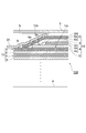
- 2 is a cross-sectional view taken along the line II-II in FIG.
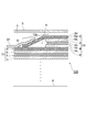
- FIG. 3 is a cross-sectional view of the outer end portion in the winding direction of the electrochemical device according to the second embodiment of the first invention.
- FIG. 4 is a cross-sectional view of the outer end in the winding direction of the electrochemical device according to the reference embodiment of the first invention.
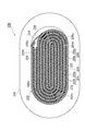
- FIG. 5 is a cross-sectional view of a lithium ion secondary battery which is an example of an electrochemical device manufactured in the embodiment of the second invention.
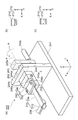
- 6A is a schematic perspective view of the electrode winding device 50 used in the embodiment of the second invention, and FIGS.
- FIGS. 6B and 6C are views of the plate 12 of the electrode winding device 50 of FIG. , 14 when viewed from the Y direction.
- 7A to 7E are schematic cross-sectional views for sequentially explaining the method for manufacturing an electrochemical device according to the embodiment of the second invention.
- FIGS. 8A to 8D are schematic cross-sectional views for sequentially explaining a reference example of the method for manufacturing an electrochemical device of the second invention.
- the wound lithium ion secondary battery 110 includes a wound body 100 having a stacked body 10 wound in a spiral shape. Electrode) 6 / first separator 8 / negative electrode 4 (second electrode) / second separator 9. The wound body 100 is enclosed in the exterior body 5 together with the electrolytic solution. A lead 22 is connected to each of the positive electrode 6 and the negative electrode 4, and protrudes outside the exterior body 5.
- the positive electrode 6 has a strip-shaped positive electrode current collector 6a and a positive electrode active material layer 6b covering both surfaces of the positive electrode current collector 6a.
- the negative electrode 4 has a strip-shaped negative electrode current collector 4a and a negative electrode active material layer 4b covering both surfaces of the negative electrode current collector 4a.
- the coverage of the positive electrode active material layer 6b on both surfaces of the positive electrode current collector 6a and the coverage of the negative electrode active material layer 4b on both surfaces of the negative electrode current collector 4a are not particularly limited. There is a tendency that the capacity of the lithium ion secondary battery 110 increases as the coverage ratio increases.
- the positive electrode active material layer 6b covers the entire both surfaces of the positive electrode current collector 6a except for the portions where the leads 22 connected to the positive electrode 6 and the negative electrode 4 are installed, respectively.
- the negative electrode active material layer 4b covers the entire surface of the body 4a. That is, as shown in FIG.
- a current collector used in a known electrochemical device can be used.
- a material obtained by forming copper, aluminum, nickel or the like into a strip shape. can be used.
- the positive electrode active material layer 6b is a layer containing a positive electrode active material (cathode active material), a conductive additive, a binder, and the like.
- Cathode active materials include insertion and extraction of lithium ions, desorption and insertion (intercalation) of lithium ions, or doping and dedoping of lithium ions and counter anions of the lithium ions (for example, PF 6 ⁇ ). If it can be made to advance reversibly, it will not specifically limit, A well-known electrode active material can be used.
- lithium cobaltate LiCoO 2
- lithium nickelate LiNiO 2
- lithium manganese spinel LiMn 2 O 4
- M is one or more elements selected from Al, Mg, Nb, Ti, Cu, Zn, and Cr
- Examples of the material of the binder include polyvinylidene fluoride (PVDF), polytetrafluoroethylene (PTFE), tetrafluoroethylene-hexafluoropropylene copolymer (FEP), and tetrafluoroethylene-perfluoroalkyl vinyl ether copolymer.
- Fluorine resins such as (PFA), ethylene-tetrafluoroethylene copolymer (ETFE), polychlorotrifluoroethylene (PCTFE), ethylene-chlorotrifluoroethylene copolymer (ECTFE), and polyvinyl fluoride (PVF). It is done.
- vinylidene fluoride-hexafluoropropylene fluorororubber VDF-HFP fluoropolymer
- vinylidene fluoride-hexafluoropropylene-tetrafluoroethylene fluororubber VDF- HFP-TFE fluorine rubber
- vinylidene fluoride-pentafluoropropylene fluorine rubber VDF-PFP fluorine rubber
- vinylidene fluoride-pentafluoropropylene-tetrafluoroethylene fluorine rubber VDF-PFP-TFE fluorine rubber
- Vinylidene fluoride-perfluoromethyl vinyl ether-tetrafluoroethylene fluorine rubber VDF-PFMVE-TFE fluorine rubber
- vinylidene fluoride-chlorotrifluoroethylene fluorine It may be used vinylidene fluoride-based fluorine rubbers such as rubber (VDF-PFMVE-TFE fluorine rubber), vinyl
- polyethylene, polypropylene, polyethylene terephthalate, aromatic polyamide, cellulose, styrene / butadiene rubber, isoprene rubber, butadiene rubber, ethylene / propylene rubber, and the like may be used as the binder.
- thermoplastic elastomeric polymers such as styrene / butadiene / styrene block copolymers, hydrogenated products thereof, styrene / ethylene / butadiene / styrene copolymers, styrene / isoprene / styrene block copolymers, and hydrogenated products thereof. May be used.
- syndiotactic 1,2-polybutadiene, ethylene / vinyl acetate copolymer, propylene / ⁇ -olefin (2 to 12 carbon atoms) copolymer, and the like may be used.
- an electron conductive conductive polymer or an ion conductive conductive polymer may be used as the binder.
- the electron conductive conductive polymer include polyacetylene.
- the binder since the binder also exhibits the function of the conductive assistant particles, it is not necessary to add the conductive assistant.
- ion-conductive conductive polymer for example, those having ion conductivity such as lithium ion can be used.
- polymer compounds polyether-based polymer compounds such as polyethylene oxide and polypropylene oxide
- Examples include Li (CF 3 SO 2 ) 2 N, LiN (C 2 F 5 SO 2 ) 2 lithium salt, or a composite of alkali metal salt mainly composed of lithium.
- the polymerization initiator used for the combination include a photopolymerization initiator or a thermal polymerization initiator that is compatible with the above-described monomer.
- the binder content is preferably 0.5 to 6% by mass based on the mass of the active material layer.
- the binder content is preferably 0.5 to 6% by mass based on the mass of the active material layer.
- the binder content is less than 0.5% by mass, the amount of the binder is too small and a tendency to fail to form a strong active material layer increases.
- the content rate of a binder exceeds 6 mass%, the quantity of the binder which does not contribute to an electric capacity will increase, and the tendency for it to become difficult to obtain sufficient volume energy density becomes large. In this case, particularly, when the electronic conductivity of the binder is low, the electric resistance of the active material layer is increased, and a tendency that a sufficient electric capacity cannot be obtained increases.
- Examples of the conductive assistant include carbon blacks, carbon materials, metal fine powders such as copper, nickel, stainless steel, and iron, a mixture of carbon materials and metal fine powders, and conductive oxides such as ITO.
- the content of the conductive assistant is preferably 0.5 to 6% by mass based on the mass of the active material layer.
- the negative electrode active material layer 4b is a layer containing a negative electrode active material (anode active material), a conductive additive, a binder, and the like.
- the anode active material includes insertion and extraction of lithium ions, desorption and insertion (intercalation) of lithium ions, or doping and dedoping of lithium ions and a counter anion of the lithium ions (for example, PF 6 ⁇ ).
- a known anode active material can be used without particular limitation as long as it can proceed reversibly.
- an active material for example, natural graphite, artificial graphite, non-graphitizable carbon, graphitizable carbon, low-temperature calcined carbon and other carbon materials, lithium such as Al, Si, Sn, Si, etc.
- examples thereof include amorphous metals such as SiO, SiO x , SiO 2 and SnO 2 , lithium titanate (Li 4 Ti 5 O 12 ), and TiO 2 .
- a carbon material is preferable, and a carbon material having an interlayer distance d 002 of 0.335 to 0.338 nm and a crystallite size Lc 002 of 30 to 120 nm is more preferable.
- Examples of the carbon material satisfying such conditions include artificial graphite, MCF (mesocarbon fiber), MCMB (mesocarbon microbead), and the like.
- the interlayer distance d 002 and the crystallite size Lc 002 can be obtained by an X-ray diffraction method.
- the binder and the conductive auxiliary are the same as those for the positive electrode.
- the separators 8 and 9 for example, those formed of an electrically insulating porous material can be used.
- the electrically insulating material include resin materials such as heat-resistant resins such as polyolefins such as polyethylene and polypropylene, polyesters, and polyacrylonitrile (PAN). These may be a single layer or a laminate of various resins.
- the production method of the porous body with the resin is not particularly limited, and examples thereof include a stretching method and a phase change method.
- a woven fabric or a nonwoven fabric of these resin fibers may be used.
- the thickness of the positive electrode 6 and the negative electrode 4 is not particularly limited.
- the thickness of the positive electrode current collector 6a or the negative electrode current collector 4a can be about 6 to 25 ⁇ m.
- the thickness of the positive electrode active material layer 6b or the negative electrode active material layer 4b can be about 20 to 200 ⁇ m.
- the thickness of the separators 8 and 9 can be about 10 to 100 ⁇ m.
- the length of the strip-like positive electrode 6 and negative electrode 4 in the winding direction is not particularly limited, and can be set according to the number of windings and the capacity.
- the total length before winding can be 50 to 150 mm.
- the length of the central portion when the laminate is wound can be about 10 to 15 mm, for example.
- the length (width) of the positive electrode 6, the negative electrode 4, and the separators 8 and 9 in the short direction is not particularly limited, but can be, for example, about 11 to 18 mm.
- the number of windings is not particularly limited, but may be, for example, 4 to 8 times, more specifically 6 times.
- the exterior body 5 is filled with an electrolytic solution L.
- This electrolytic solution is mainly impregnated in the wound body 100 of the laminate 10, but is also filled in the gap between the wound body 100 and the exterior body 5.
- sealing or the like is performed in a vacuum so that no gas is contained in the outer package 5.
- the electrolytic solution is not particularly limited.
- an electrolytic solution containing a lithium salt an electrolytic aqueous solution or an electrolytic solution using an organic solvent
- the electrolyte aqueous solution is preferably an electrolytic solution (non-aqueous electrolytic solution) using an organic solvent because the electrochemical decomposition voltage is low, and the withstand voltage during charging is limited to be low.
- a lithium salt dissolved in a non-aqueous solvent is preferably used.
- lithium salt examples include LiPF 6 , LiClO 4 , LiBF 4 , LiAsF 6 , LiCF 3 SO 3 , LiCF 3 , CF 2 SO 3 , LiC (CF 3 SO 2 ) 3 , LiN (CF 3 SO 2 ) 2 , A salt such as LiN (CF 3 CF 2 SO 2 ) 2 , LiN (CF 3 SO 2 ) (C 4 F 9 SO 2 ), LiN (CF 3 CF 2 CO) 2 , LiBOB or the like can be used.
- these salts may be used individually by 1 type, and may use 2 or more types together.
- organic solvent for example, propylene carbonate, ethylene carbonate, diethyl carbonate, dimethyl carbonate, methyl ethyl carbonate and the like are preferable. These may be used alone or in combination of two or more at any ratio.
- the electrolytic solution may be a gel electrolyte obtained by adding a gelling agent in addition to the liquid state.
- the wound body 100 is formed by winding the four-layer laminate 10 in a flat spiral shape, but the structure in the vicinity of the winding center p is not particularly limited. It is sufficient that the negative electrode 4 is not short-circuited.
- the outer end 8e in the winding direction of the first separator 8 is inclined toward the winding center p before the negative electrode (second electrode) 4 and is in contact with the upper surface of the second separator 9, and the positive electrode (first The outer end 6e in the winding direction of the electrode 6 is inclined toward the winding center p before the negative electrode (second electrode) 4 and is in contact with the second separator 9 and at the inner peripheral side positive electrode (first electrode) 6i.
- the outside in the winding direction is a direction along the vortex of the laminated body 10 to be wound and a direction that can be separated from the end portion 10 e of the laminated body 10.
- the end 6 e of the positive electrode 6 is preferably bent along the end 8 e of the first separator 8.
- the length of each protrusion is not particularly limited.
- the first separator 8 may protrude about 2 to 4 mm from the negative electrode (second electrode) 4.
- the second separator 9 can protrude about 4 to 8 mm, and the positive electrode (first electrode) 6 can protrude about 5 to 10 mm. What is necessary is just to measure protrusion length along the surface of the positive electrode 6i of an inner peripheral side, for example.
- the gap formed between the end 6e of the outermost positive electrode (first electrode) 6 and the inner peripheral positive electrode (first electrode) 6i is defined as the first separator 8 and the second separator. 9 can be suitably closed. Thereby, even when gas is generated in the electrochemical device during use, the size of the bubbles formed in the end 10e of the wound body 100 can be reduced, so that the adhesive tape 33 can be peeled off by lifting the positive electrode 6 or the like. In addition, formation of gaps between the positive electrode 6 and the negative electrode 4 and the separators 8 and 9, displacement, and the like are suppressed. Thereby, degradation of the capacity and impedance accompanying use can be suppressed.
- the length of each of the four layers of the laminate 10 may be determined in advance so that the position of the end portion 10e of the winding end satisfies the above-described conditions. After winding, the length of the end of each layer may be cut to define the protruding length.
- the outer end 8e in the winding direction of the first separator 8 is inclined toward the winding center p before the negative electrode (second electrode) 6, and its lower surface is in contact with the second separator 9 and the tip portion. Is in contact with the positive electrode 6i on the inner peripheral side, and the outer end 6e in the winding direction of the positive electrode (first electrode) 6 is inclined toward the winding center p before the negative electrode (second electrode) 4, and is on the inner peripheral side. In contact with the positive electrode 6i.
- the end 6 e of the positive electrode 6 is preferably bent along the end 8 e of the first separator 8. This also makes it possible to suppress the formation of a gap between the end 6e of the outermost positive electrode (first electrode) 6 and the inner peripheral positive electrode (first electrode) 6i as compared with the conventional case.
- the wound electrochemical device is a lithium ion secondary battery
- the wound electrochemical device of the present invention is not limited to a lithium ion secondary battery.
- a secondary battery other than a lithium ion secondary battery such as a metal lithium secondary battery, a lithium capacitor, an electric double layer capacitor, an electrolytic capacitor, or the like may be used.
- a material suitable for each electrochemical device may be used as the electrode active material.
- acetylene black, graphite, graphite, activated carbon, or the like is used as the active material contained in the cathode active material-containing layer and the anode active material-containing layer.
- a quaternary ammonium salt such as tetraethylammonium tetrafluoroborate (TEA-BF4) dissolved in an organic solvent such as propylene carbonate (PC), diethylene carbonate (DEC), or acetonitrile.
- an aluminum foil having an anodized film and an aluminum foil having no anodized film may be used as electrodes, and a known electrolyte may be used.
- Example A1 An electric double layer capacitor (EDLC) according to the first embodiment (FIG. 2) of the first invention was created.
- An aluminum foil with a thickness of 20 ⁇ m was used as the current collector, an activated carbon-containing layer with a thickness of 18 ⁇ m was used as the active material layer, a cellulose sheet with a thickness of 30 ⁇ m was used as the separator, and TEA-BF4-PC was used as the electrolyte.
- the first separator 8 protrudes from the negative electrode (second electrode) 4 by approximately 3 mm
- the second separator 9 protrudes by approximately 6 mm
- the positive electrode (first electrode) 6 protrudes by approximately 9 mm. Protruded.
- the electrode width was 12.5 mm and the number of windings was six.
- Example A2 EDLC
- the structure of the outer end in the winding direction was the same as that of Example A1 except that the structure of the second embodiment (FIG. 3) was used. Specifically, at the outer end in the winding direction, the first separator 8 protrudes about 6 mm from the negative electrode (second electrode) 4, the second separator 9 protrudes about 3 mm, and the positive electrode (first electrode) 6 was protruded by about 9 mm.
- Example A3 As the positive electrode 6, a lithium manganate layer was provided as a 100 ⁇ m active material layer on a current collector having a thickness of 20 ⁇ m, and a LiPF 6 PC solution was used as an electrolyte solution.
- a lithium ion secondary battery (LIB) according to the first embodiment was created.
- Example A4 LIB
- a lithium manganate layer was provided as a 100 ⁇ m active material layer on a current collector having a thickness of 20 ⁇ m, and a LiPF 6 PC solution was used as an electrolyte solution.
- a lithium ion secondary battery according to the second embodiment was created.
- Example A1 EDLC
- the structure of the outer end in the winding direction was the same as that of Example A1 except that the structure shown in FIG. 4 was used. Specifically, at the outer end in the winding direction, the first separator 8 protrudes from the negative electrode (second electrode) 4 by about 3 mm, the second separator 9 protrudes by about 3 mm, and the positive electrode (first electrode). 6 was protruded by about 9 mm.
- Example A2 LIB
- the structure of the outer end in the winding direction was the same as that of Example A3 except that the structure shown in FIG. 4 was used. Specifically, at the outer end in the winding direction, the first separator 8 protrudes from the negative electrode (second electrode) 4 by about 3 mm, the second separator 9 protrudes by about 3 mm, and the positive electrode (first electrode). 6 was protruded by about 9 mm.
- the wound lithium ion secondary battery 110 includes a substantially elliptical wound body 200 in which a belt-like positive electrode 4 and a belt-like negative electrode 206 are wound so as to sandwich a belt-like separator 208. And a container 205 that accommodates the wound body 200. Leads 222 are connected to the positive electrode 204 and the negative electrode 206 of the wound body 200, respectively, and project outside the container 205 although not shown.
- the positive electrode 204 has a strip-shaped positive electrode current collector 204a and a positive electrode active material layer 204b covering both surfaces of the positive electrode current collector 204a.
- the negative electrode 206 includes a strip-shaped negative electrode current collector 206a and a negative electrode active material layer 206b covering both surfaces of the negative electrode current collector 206a.
- the positive electrode current collector 204a is entirely covered with the positive electrode active material layer 204b except for the portion where the lead 222 connected to the positive electrode 204 and the negative electrode 206 is installed, and the negative electrode current collector is covered.
- the whole surface of the body 206a is covered with the negative electrode active material layer 206b.
- both surfaces of one layer of the positive electrode 204 are adjacent to the negative electrode 206 via the separator 208, and both surfaces of the single layer of negative electrode 206 are adjacent to the positive electrode 204 via the separator, except for the outermost peripheral portion.
- the center side end portion 206 d of the negative electrode 206 is sandwiched between U-shaped portions 204 u formed by the positive electrode 204 located on the center side of the wound body 200, and the center side end portion 204 d of the positive electrode 204 is sandwiched between the wound body 200. It is sandwiched between U-shaped portions 206u formed by the negative electrode 206 located on the center side, and the positive electrode 204 and the negative electrode 206 are arranged symmetrically on the center side.
- both surfaces of the center-side end portion 204d of one layer of the positive electrode 204 are adjacent to the negative electrode 206 via the separator 208, respectively, and both surfaces of the center-side end portion 206d of the single layer negative electrode 206 are respectively adjacent to the positive electrode 204 via the separator. ing.
- both surfaces of the positive electrode 204 face the negative electrode 206, and both surfaces of the negative electrode 206 face the positive electrode 204, and the positive electrode 204 and the negative electrode 206 do not face each other.
- the portion is not formed on the center side of the wound body 200. Further, except for the connection position of the lead, any of the opposing positive electrode and negative electrode is not formed with a portion lacking the active material. Therefore, in this embodiment, the capacity
- the outer end portion 206c of the negative electrode 206 disposed on the outermost peripheral side is disposed on the inner peripheral side.
- the outer end portion 204 c of the positive electrode 204 extends in the winding direction of the wound body 200 (longitudinal direction of the negative electrode 206). Therefore, a gap 234 is generated between the outer end 206 c of the negative electrode 206 extending in the winding direction of the wound body 200 and the outer periphery of the wound body 200.
- the outer end 206c of the negative electrode 206 extending in the winding direction of the wound body 200 is fixed to the outer peripheral surface of the wound body 200 with an adhesive tape 233 so as to be pushed toward the inner peripheral side of the wound body 200. ing.
- a current collector used in a known electrochemical device can be used.
- a material obtained by forming copper, aluminum, nickel or the like into a strip shape. can be used.
- the positive electrode active material layer 204b is a layer including a positive electrode active material (cathode active material), a conductive additive, a binder, and the like.
- Cathode active materials include insertion and extraction of lithium ions, desorption and insertion (intercalation) of lithium ions, or doping and dedoping of lithium ions and counter anions of the lithium ions (for example, PF 6 ⁇ ). If it can be made to advance reversibly, it will not specifically limit, A well-known electrode active material can be used.
- lithium cobaltate LiCoO 2
- lithium nickelate LiNiO 2
- lithium manganese spinel LiMn 2 O 4
- M is one or more elements selected from Al, Mg, Nb, Ti, Cu, Zn, and Cr
- Examples of the material of the binder include polyvinylidene fluoride (PVDF), polytetrafluoroethylene (PTFE), tetrafluoroethylene-hexafluoropropylene copolymer (FEP), and tetrafluoroethylene-perfluoroalkyl vinyl ether copolymer.
- Fluorine resins such as (PFA), ethylene-tetrafluoroethylene copolymer (ETFE), polychlorotrifluoroethylene (PCTFE), ethylene-chlorotrifluoroethylene copolymer (ECTFE), and polyvinyl fluoride (PVF). It is done.
- vinylidene fluoride-hexafluoropropylene fluorororubber VDF-HFP fluoropolymer
- vinylidene fluoride-hexafluoropropylene-tetrafluoroethylene fluororubber VDF- HFP-TFE fluorine rubber
- vinylidene fluoride-pentafluoropropylene fluorine rubber VDF-PFP fluorine rubber
- vinylidene fluoride-pentafluoropropylene-tetrafluoroethylene fluorine rubber VDF-PFP-TFE fluorine rubber
- Vinylidene fluoride-perfluoromethyl vinyl ether-tetrafluoroethylene fluorine rubber VDF-PFMVE-TFE fluorine rubber
- vinylidene fluoride-chlorotrifluoroethylene fluorine It may be used vinylidene fluoride-based fluorine rubbers such as rubber (VDF-PFMVE-TFE fluorine rubber), vinyl
- polyethylene, polypropylene, polyethylene terephthalate, aromatic polyamide, cellulose, styrene / butadiene rubber, isoprene rubber, butadiene rubber, ethylene / propylene rubber, and the like may be used as the binder.
- thermoplastic elastomeric polymers such as styrene / butadiene / styrene block copolymers, hydrogenated products thereof, styrene / ethylene / butadiene / styrene copolymers, styrene / isoprene / styrene block copolymers, and hydrogenated products thereof. May be used.
- syndiotactic 1,2-polybutadiene, ethylene / vinyl acetate copolymer, propylene / ⁇ -olefin (2 to 12 carbon atoms) copolymer, and the like may be used.
- an electron conductive conductive polymer or an ion conductive conductive polymer may be used as the binder.
- the electron conductive conductive polymer include polyacetylene.
- the binder since the binder also exhibits the function of the conductive assistant particles, it is not necessary to add the conductive assistant.
- ion-conductive conductive polymer for example, those having ion conductivity such as lithium ion can be used.
- polymer compounds polyether-based polymer compounds such as polyethylene oxide and polypropylene oxide
- Examples include Li (CF 3 SO 2 ) 2 N, LiN (C 2 F 5 SO 2 ) 2 lithium salt, or a composite of alkali metal salt mainly composed of lithium.
- the polymerization initiator used for the combination include a photopolymerization initiator or a thermal polymerization initiator that is compatible with the above-described monomer.
- the binder content is preferably 0.5 to 6% by mass based on the mass of the active material layer.
- the binder content is preferably 0.5 to 6% by mass based on the mass of the active material layer.
- the binder content is less than 0.5% by mass, the amount of the binder is too small and a tendency to fail to form a strong active material layer increases.
- the content rate of a binder exceeds 6 mass%, the quantity of the binder which does not contribute to an electric capacity will increase, and the tendency for it to become difficult to obtain sufficient volume energy density becomes large. In this case, particularly, when the electronic conductivity of the binder is low, the electric resistance of the active material layer is increased, and a tendency that a sufficient electric capacity cannot be obtained increases.
- Examples of the conductive assistant include carbon blacks, carbon materials, metal fine powders such as copper, nickel, stainless steel, and iron, a mixture of carbon materials and metal fine powders, and conductive oxides such as ITO.
- the content of the conductive assistant is preferably 0.5 to 6% by mass based on the mass of the active material layer.
- the negative electrode active material layer 206b is a layer containing a negative electrode active material (anode active material), a conductive additive, a binder, and the like.
- the anode active material includes insertion and extraction of lithium ions, desorption and insertion (intercalation) of lithium ions, or doping and dedoping of lithium ions and a counter anion of the lithium ions (for example, PF 6 ⁇ ).
- a known anode active material can be used without particular limitation as long as it can proceed reversibly.
- an active material for example, natural graphite, artificial graphite, non-graphitizable carbon, graphitizable carbon, low-temperature calcined carbon and other carbon materials, lithium such as Al, Si, Sn, Si, etc.
- examples thereof include amorphous metals such as SiO, SiO x , SiO 2 and SnO 2 , lithium titanate (Li 4 Ti 5 O 12 ), and TiO 2 .
- a carbon material is preferable, and a carbon material having an interlayer distance d 002 of 0.335 to 0.338 nm and a crystallite size Lc 002 of 30 to 120 nm is more preferable.
- Examples of the carbon material satisfying such conditions include artificial graphite, MCF (mesocarbon fiber), MCMB (mesocarbon microbead), and the like.
- the interlayer distance d 002 and the crystallite size Lc 002 can be obtained by an X-ray diffraction method.
- the binder and the conductive auxiliary are the same as those for the positive electrode.
- a separator formed of an electrically insulating porous material can be used.
- the electrically insulating material include resin materials such as heat-resistant resins such as polyolefins such as polyethylene and polypropylene, polyesters, and polyacrylonitrile (PAN). These may be a single layer or a laminate of various resins.
- the method for producing the porous film with the resin is not particularly limited, and examples thereof include a stretching method and a phase change method.
- a woven fabric or a nonwoven fabric of these resin fibers may be used.
- the thickness of the positive electrode current collector 204a or the negative electrode current collector 206a is about 6 to 25 ⁇ m.
- the thickness of the positive electrode active material layer 204b or the negative electrode active material layer 206b is about 20 to 200 ⁇ m.
- the thickness of the separator 208 is about 10 to 100 ⁇ m.
- the thickness of the adhesive tape 233 is, for example, about 30 ⁇ m.
- the length of the wound body 200 in the longitudinal direction is not particularly limited, and can be set according to the number of windings and the capacity, for example, about 10 to 15 mm.
- the length in the width direction of the wound body 200 is not particularly limited, but can be, for example, about 11 to 17 mm.
- Such a wound body 200 contains various known electrolytes.
- the electrode winding device 250 mainly includes a gantry 241, a support plate 242, a rotating shaft 243, a plate fixing part 240, and plates 212 and 214.
- the gantry 241 is arranged substantially horizontally (XY directions in FIG. 6A), and the support plate 242 is fixed to the surface of the gantry 241 substantially perpendicularly to the gantry 241.
- a rotation shaft 243 is disposed through the support plate 242, and the rotation shaft 243 can be rotated around an axis a along the Y direction by bearings 244a and 244b disposed on both sides of the support plate 242. It is supported by.
- One end of the arm 245a is fixed to one end side (the right side of FIG. 6A) of the rotating shaft 243 so as to be orthogonal to the rotating shaft 243, and a handle 245b is fixed to the other end of the arm 245a. Has been.
- a pedestal 246 is fixed to the other end side of the rotating shaft 243 (left side of FIG. 6A). Specifically, the base 246 has a hole 246 a that receives the other end of the rotating shaft 243. A notch 243a forming a flat surface portion is provided at the other end of the rotating shaft 243, and the tip of the bolt 244 screwed into the pedestal 246 comes into contact with the notch 243a of the rotating shaft. Is fixed to the rotating shaft 243, and the pedestal 246 is also rotated around the axis a of the rotating shaft v43 by the rotation of the handle 245b.
- the base 246 has a surface 246b parallel to the axis a of the rotation shaft 243.
- a pair of plates 212 and 214 are disposed so as to face each other.
- Each of the plate 212 and the plate 214 has a substantially rectangular shape with the direction of the axis a as the longitudinal direction.
- One end of each of the plate 212 and the plate 214 in the longitudinal direction is disposed on the surface 246 b of the pedestal 246.
- the thickness of the plates 212 and 214 is not particularly limited, but can be 0.1 to 1 mm, for example.
- the length in the Y-axis direction of the plates 212 and 214 can be, for example, about 30 to 100 mm, and the width in the X-axis direction can be, for example, about 5 to 30 mm.
- the length of one plate of the pair of plates 212 and 214 in the Y direction is different from the length of the other plate in the Y direction, etc.
- either the plate 212 or the plate 214 preferably protrudes in the direction of the axis a as compared to the other. In FIG. 6A, the end of the plate 212 protrudes.
- the plates 212 and 214 are sandwiched between the plates 212 and 214 by the plate fixing portion 240 so that the axis a of the rotation shaft 243 is disposed, and extend in the axis a direction of the rotation shaft 243.
- the space between the plates 212 and 214 is a region including the thickness of each of the plates 212 and 214.
- the plate 212 and the plate 214 constitute the winding core 210.
- the plates 212 and 214 may be arranged so that the plates 212 and 214 are shifted from each other in the X direction as viewed from the Y direction. As shown, the plates 212 and 214 may be arranged so as to completely overlap.
- the width X225 in the X direction determines the width of the core 210. In the present embodiment, the state shown in FIG. 6C will be described below.
- a pressing member 247 disposed to face the surface 246b of the pedestal 246 is disposed on the plate 212 and the plate 214.
- the pressing member 247 is disposed so as to cover the ends of the plate 212 and the plate 214 and is fixed to the base 246 by bolts 22 and 2 that are separated in the X direction.
- a strip-shaped separator 208 is prepared, and then, for example, the end of the plate 212 protruding compared to the other is pushed with a finger or the like.
- a gap is formed between the plate 212 and the plate 214, and for example, an intermediate portion of the separator 208 is inserted between the plate 212 and the plate 214 and fixed between the plate 212 and the plate 214.
- the separator 208 faces the side surface 212 s of the plate 212.
- the positive electrode 204 is disposed between the separators 208 hooked around the one plate 212, and the center side end portion 204 d of the positive electrode 204 is connected to the one plate 212. It arrange
- the center-side end portion 204d of the positive electrode 204 is disposed in a portion p1 between the one plate 212 and the separator 208 and far from the other plate 214.
- it can be implemented even if it is arranged in the portion p2 on the side close to the other plate 214. Since the space between the separator 208 and the plate 212 can be easily expanded on the part p1 side, an effect that the positive electrode 204 is easily arranged on the part p1 side is obtained.
- the separator 208 is hooked on the plate 212.
- the separator 208 is placed around the plate 212. Even if it is hooked, it can be carried out, and these may be performed simultaneously.
- the handle 245b of FIG. 6 (a) is turned in the direction A of FIG. 6, and as shown in FIG. 7 (c), the rotary shaft 203 is rotated approximately halfway around the axis a, thereby the other plate.
- a positive electrode 204 and a separator 208 sandwiching the positive electrode 204 from both sides are hooked around 214.
- the side surface 214s of the other plate 214 is opposed to the separator 208 / positive electrode 204 / separator 208 laminate (the second step is completed).
- the rotation angle is not particularly limited, and the positive electrode 204 and the separator 208 that sandwiches the positive electrode 204 from both sides may be caught by the other plate.
- the negative electrode 206 is disposed along the portion 208 pa of the separator 208 close to the other plate 214 and extending in the direction away from the core 210, and the negative electrode 206. Is disposed between the other plate 214 and the separator 208 (the third step is completed).
- the center side end portion 206d of the negative electrode 206 in a portion p3 between the other plate 214 and the separator 208, which is far from the one plate 212. Implementation is possible even if it is arranged in the portion p4 on the near side. Since the space between the separator 208 and the plate 212 can be easily widened on the part p3 side, an effect that the negative electrode 206 is easily arranged on the part p3 side is obtained.
- the electrochemical device is obtained by a known method such as drawing out the plates 212 and 214 constituting the core 210 from the wound body 200, immersing them in an electrolytic solution, and enclosing them in a container.
- the electrochemical device having the above-described configuration can be suitably manufactured.
- each of the pair of plates 212 and 214 of the winding core 210 is opposed to the positive electrode 204 or the negative electrode 206, and both surfaces of the plates 212 and 214 are separators. 208 is not caught.
- the plates 212 and 214 are less likely to catch the separator 208 of the wound body 200, thereby improving operability and increasing productivity.
- the reason can be considered as follows.
- the separator surface is poorly slidable, and if the separator is in contact with both sides of the core, it will get caught on the core.
- the surface of the electrode is slippery and is not easily caught by the core even if it is in contact with the core. Therefore, even if one side of the core is in contact with the separator, it is considered that if the other side of the core is in contact with the electrode, this surface slips and the force that the separator is caught on the core is weakened.
- the wound electrochemical device manufactured in this way can be used for power sources such as self-propelled micromachines and IC cards, as well as distributed power sources placed on or in printed boards. It is.
- the wound electrochemical device is a lithium ion secondary battery
- the wound electrochemical device of the present invention is not limited to a lithium ion secondary battery.
- a secondary battery other than a lithium ion secondary battery such as a metal lithium secondary battery, a lithium capacitor, or an electric double layer capacitor (Electric Double Layer Capacitor) may be used.
- a material suitable for each electrochemical device may be used as the electrode active material.
- an electric double layer capacitor for example, acetylene black, graphite, graphite, activated carbon or the like is used as the active material contained in the cathode active material-containing layer and the anode active material-containing layer.
- acetylene black, graphite, graphite, activated carbon or the like is used as the active material contained in the cathode active material-containing layer and the anode active material-containing layer.
- the electrolyte solution for example, a quaternary ammonium salt such as tetraethylammonium tetrafluoroborate dissolved in an organic solvent such as propylene carbonate, diethylene carbonate, acetonitrile, or the like is used.
- the rotating shaft 243 of the electrode winding device 250 may not be manually operated but may be rotated by the power of a motor or the like.
- the electrode winding device 250 has the rotation axis a in the total area of the plates 212 and 214, but the rotation axis a exists outside the total area, that is, even if it is eccentric.
- the cross-sectional shape of the XZ plane of the plates 212 and 214 is not particularly limited to a rectangle, and may be round like a semi-elliptical shape.
- the core 210 may have a gap between the plate 212 and the plate 214.
- Example B1 As shown in FIGS. 7A to 7E, the lithium ion secondary battery was wound 100 times.
- the positive electrode current collector was aluminum foil
- the negative electrode current collector was copper foil
- the positive electrode active material was lithium manganate
- the negative electrode active material was graphite.
- the thickness of the core plate was 0.5 mm, and the size was 14 mm ⁇ 60 mm.
- the separator was a porous film made of PAN (polyacrylonitrile).
- Example B2 The separator was the same as Example B1, except that the nonwoven fabric was made of cellulose.
- Example B1 was the same as Example B1 except that the winding was performed as shown in FIGS.
- the core 210 caught on the separator 208 was 0 in 100 in Example B1, 5 in 100 in Example B2, and 100 in Comparative Example B1. There were 98.
Landscapes
- Engineering & Computer Science (AREA)
- Power Engineering (AREA)
- Manufacturing & Machinery (AREA)
- Chemical & Material Sciences (AREA)
- Chemical Kinetics & Catalysis (AREA)
- Electrochemistry (AREA)
- General Chemical & Material Sciences (AREA)
- Microelectronics & Electronic Packaging (AREA)
- Materials Engineering (AREA)
- Secondary Cells (AREA)
Abstract
巻回された積層体10を有し、積層体10は、外側から順に、第一電極6/第一セパレータ8/第二電極4/第二セパレータ9という構造を有する巻回体100と、電解液Lと、巻回体及び電解液を収容する外装体5と、を備え、積層体の巻回方向の外側端部10eにおいて、下記を全て満たす。(a)第二電極よりも第一セパレータ及び第二セパレータが巻回方向外側に突出する。(b)第一第セパレータ及び第二セパレータよりも第一電極が巻回方向外側に突出する。(c)第一セパレータの巻回方向外側端部が第二電極より先で巻回の中心側に傾斜し第二セパレータの上面と接触し、かつ、第一電極の巻回方向外側端部が第二電極より先で巻回の中心側に傾斜し、第二セパレータと接触すると共に内周側の第一電極と接触する。
Description
本発明は、電気化学デバイス及び、電気化学デバイスの製造方法に関する。
従来より、外側から順に、第一電極/第一セパレータ/第二電極/第二セパレータという構造の積層体が中心に向かって渦状に巻回された巻回型の電気化学デバイスが知られている。積層体の巻回方向外側端部は、通常粘着テープ等で固定されることが多い。
また、従来より、互いに対向し回転軸方向に延びる巻芯の周りに電極やセパレータを巻回させる巻回型の電気化学デバイスの製造方法が知られている。
(第1の発明)
このような巻回型の電気化学デバイスにおいては、使用を重ねると容量が低下したり、インピーダンスが高くなる傾向があり、問題となっている。
このような巻回型の電気化学デバイスにおいては、使用を重ねると容量が低下したり、インピーダンスが高くなる傾向があり、問題となっている。
第1の発明は上記課題に鑑みてなされたものであり、容量やインピーダンスが劣化し難い電気化学デバイスを提供することを目的とする。
(第2の発明)
薄型の巻回型電気化学デバイスを作成する場合には、巻芯の厚みを薄くしておく必要があり、通常、一対の対向する板を有する巻芯を用いる場合が多い。そして、本発明者等は、一対の対向する板を有する巻芯に対して電極及びセパレータを巻回したのちに、巻回体から巻芯を抜き出す場合に、巻芯が巻回体に引っかかって不良品を発生させる場合が多いことを見出した。
薄型の巻回型電気化学デバイスを作成する場合には、巻芯の厚みを薄くしておく必要があり、通常、一対の対向する板を有する巻芯を用いる場合が多い。そして、本発明者等は、一対の対向する板を有する巻芯に対して電極及びセパレータを巻回したのちに、巻回体から巻芯を抜き出す場合に、巻芯が巻回体に引っかかって不良品を発生させる場合が多いことを見出した。
さらに本発明者等が検討したところ、巻回体において、巻芯の板の両面がセパレータに挟まれていると、巻芯が巻回体中のセパレータに引っかかって特に不良品が発生しやすいことを見出した。
例えば、図8の(a)に示すように、巻芯210の一方の板212のみに対してセパレータ208を引っ掛け、図8の(b)に示すように巻芯210を回転軸a周りに半回転し、図8の(c)に示すように他方の板214とセパレータ208との間に一方の電極204を挿入すると共に、セパレータ208間に他方の電極206を挿入し、図8の(d)に示すように巻芯210を巻回した場合、一方の板212がセパレータ208のみに取り囲まれるため、この部分で板212がセパレータ208に引っかかりやすいことが判明した。
第2の発明は上記課題に鑑みてなされたものであり、巻芯を容易に抜くことのできる巻回型の電気化学デバイスの製造方法を提供することを目的とする。
(第1の発明)
本発明者等が検討したところ、このような巻回型の電気化学デバイスにおいて、使用を重ねた場合に容量やインピーダンスが劣化する原因の1つが、使用すると電気化学デバイス内に発生し蓄積していくガスにあることを見出した。
本発明者等が検討したところ、このような巻回型の電気化学デバイスにおいて、使用を重ねた場合に容量やインピーダンスが劣化する原因の1つが、使用すると電気化学デバイス内に発生し蓄積していくガスにあることを見出した。
具体的には、例えば、図4に示すように、積層体10の巻回方向の外側端部10eにおいて、最外周の第一電極6と、内周側の第一電極6iとの間に大きな隙間Vがあると、電気化学デバイス内で発生するガスがこの隙間Vに気泡として蓄積し、第一電極6を持ち上げて粘着テープ33を剥離させたり、電極4,6と、セパレータ8,9間に隙間やズレを生じさせたりし、これにより、容量やインピーダンスの劣化が起こることが判明した。
第1の発明に係る電気化学デバイスは、巻回された積層体を有し、前記積層体は、外側から順に、第一電極/第一セパレータ/第二電極/第二セパレータという構造を有する巻回体と、電解液と、巻回体及び電解液を収容する外装体とを備える。そして、積層体の巻回方向の外側端部において、以下の(a)~(c)を全て満たす。
(a)第二電極よりも第一セパレータ及び第二セパレータが巻回方向外側に突出する。
(b)第一第セパレータ及び第二セパレータよりも第一電極が巻回方向外側に突出する。
(c)第一セパレータの巻回方向外側端部が第二電極より先で巻回の中心側に傾斜し第二セパレータの上面と接触し、かつ、第一電極の巻回方向外側端部が第二電極より先で巻回の中心側に傾斜し、第二セパレータと接触すると共に内周側の第一電極と接触している、又は、
第一セパレータの巻回方向外側端部が第二電極より先で巻回の中心側に傾斜し、第二セパレータと接触すると共に内周側の第一電極と接触し、かつ、第一電極の巻回方向外側端部が第二電極より先で巻回の中心側に傾斜し内周側の第一電極と接触している。
(a)第二電極よりも第一セパレータ及び第二セパレータが巻回方向外側に突出する。
(b)第一第セパレータ及び第二セパレータよりも第一電極が巻回方向外側に突出する。
(c)第一セパレータの巻回方向外側端部が第二電極より先で巻回の中心側に傾斜し第二セパレータの上面と接触し、かつ、第一電極の巻回方向外側端部が第二電極より先で巻回の中心側に傾斜し、第二セパレータと接触すると共に内周側の第一電極と接触している、又は、
第一セパレータの巻回方向外側端部が第二電極より先で巻回の中心側に傾斜し、第二セパレータと接触すると共に内周側の第一電極と接触し、かつ、第一電極の巻回方向外側端部が第二電極より先で巻回の中心側に傾斜し内周側の第一電極と接触している。
本発明によれば、最外周の第一電極の端部と、内側周の第一電極との間にできる隙間が、第一セパレータ及び第二セパレータによって好適に塞がれるので隙間の体積を少なくすることができる。これにより、この隙間に発生する気泡による、電極の持ち上げや、電極セパレータ間の隙間の形成等の不具合が抑制される。
ここで、(c)において前者である、すなわち、第一セパレータの巻回方向外側端部が第二電極より先で中心側に傾斜し第二セパレータの上面と接触し、かつ、第一電極の巻回方向外側端部が第二電極より先で巻回の中心側に傾斜し、第二セパレータと接触すると共に内周側の第一電極と接触していることが好ましい。
これによれば、第一電極が第一セパレータと第二セパレータの両方に接するため、巻回時や使用時における第一電極と、両セパレータとの間での位置ずれが起きにくく、隙間を特に小さくしやすい。
具体的には、電気化学デバイスのうち、特にリチウムイオン二次電池等においては、充放電時に電極の膨張と収縮が生じることが知られている。この様な場合に、巻回端部の隙間の大きさを一定に保とうとすると、電極およびセパレータが端部において十分に固定されていることが好ましい。本発明のように比較的微小な領域で固定の必要がある場合、セパレータの切断端面を電極との固定箇所とすることが望ましい。セパレータの切断端面は切断加工の際に機械的硬度が高くなる傾向があり、切断端面と電極とを接触させることにより、電極とセパレータとを強固に固定できるからである。
そして、(c)の内の前者の構造である場合、第一セパレータおよび第二セパレータの切断端部が、いずれも最外層の第一電極に直接押しつけられることとなる。そのため、より強固に第一セパレータおよび第二セパレータと第一電極とを固定できる傾向がある。その結果、充放電時の電極の膨張と収縮を経由しても隙間の拡大が少なくなり、本発明の効果がより高く発揮される。
(第2の発明)
第2の発明に係る電気化学デバイスの製造方法は、互いに対向し回転軸方向に延びる一対の板を有する巻芯に対して、セパレータが、一方の上記板のみを取り囲むように引っ掛けられ、かつ、一方の電極が、上記引っ掛けられたセパレータの間に、上記一方の電極の端部が上記一方の板と上記セパレータとの間に位置するように配置された状態を得る第一工程と、
上記第一工程後に上記巻芯を上記回転軸周りに回転することにより、上記一方の電極及び上記一方の電極を両側から挟む上記セパレータを上記他方の板に引っ掛ける第二工程と、
上記第二工程後に、上記セパレータにおける上記他方の板に近い側であってかつ上記巻芯から離れる方向に伸びる部分に沿って他方の電極を配置すると共に上記他方の電極の端部を上記他方の板と上記セパレータとの間に配置する第三工程と、
上記第三工程後に、前記巻芯を上記回転軸周りにさらに回転して上記セパレータ、上記一方の電極、及び、上記他方の電極による巻回体を得る第四工程と、
上記巻回体から上記一対の板を抜き取る抜取工程と、を備える。
第2の発明に係る電気化学デバイスの製造方法は、互いに対向し回転軸方向に延びる一対の板を有する巻芯に対して、セパレータが、一方の上記板のみを取り囲むように引っ掛けられ、かつ、一方の電極が、上記引っ掛けられたセパレータの間に、上記一方の電極の端部が上記一方の板と上記セパレータとの間に位置するように配置された状態を得る第一工程と、
上記第一工程後に上記巻芯を上記回転軸周りに回転することにより、上記一方の電極及び上記一方の電極を両側から挟む上記セパレータを上記他方の板に引っ掛ける第二工程と、
上記第二工程後に、上記セパレータにおける上記他方の板に近い側であってかつ上記巻芯から離れる方向に伸びる部分に沿って他方の電極を配置すると共に上記他方の電極の端部を上記他方の板と上記セパレータとの間に配置する第三工程と、
上記第三工程後に、前記巻芯を上記回転軸周りにさらに回転して上記セパレータ、上記一方の電極、及び、上記他方の電極による巻回体を得る第四工程と、
上記巻回体から上記一対の板を抜き取る抜取工程と、を備える。
本発明によれば、第四工程後の巻回体において、巻芯のいずれの板も片面が電極と対向し、いずれの板も両面がセパレータに挟まれることがない。これにより、抜取工程において、一対の板をそれぞれ巻回体から容易に抜き出すことができ、生産性が上がる。
ここで、第一工程において、セパレータを、巻芯の一方の板のみを取り囲むように引っ掛けた後に、一方の電極を、引っ掛けられたセパレータの間に、一方の電極の端部が一方の板とセパレータとの間に位置するように配置することが好ましい。
これによれば、一方の電極の配置が容易となる。
また、第一工程において、一方の電極の端部を、一方の板とセパレータとの間の内、他方の板とは遠い側の部分に配置することが好ましい。
これによれば、一方の電極の配置が容易となる。
また、第三工程において、他方の電極の端部を、他方の板とセパレータとの間の内、一方の板とは遠い側の部分に配置することが好ましい。
これによれば、他方の電極の配置が容易となる。
また、セパレータは、樹脂多孔膜であると好ましい。樹脂多孔膜は特に巻回体から抜く際に板に、引っかかりやすいので効果的である。
また、セパレータの樹脂は、ポリアクリロニトリルであることが好ましい。ポリアクリロニトリルは、特にすべりが悪く引っかかりやすいので効果的である。
第1の発明によれば、容量やインピーダンスの維持率が高い電気化学デバイスを提供できる。
第2の発明によれば、巻芯を容易に抜くことのできる巻回型の電気化学デバイスの製造方法が提供される。
以下、図面を参照しながら本発明の好適な実施形態について詳細に説明する。なお、図面中、同一又は相当部分には同一符号を付し、重複する説明は省略する。また、上下左右等の位置関係は、特に断らない限り、図面に示す位置関係に基づくものとする。更に、図面の寸法比率は図示の比率に限られるものではない。
(第1の発明)
(第一実施形態)
まず、第1の発明の実施形態に係る巻回型電気化学デバイスの一例としての巻回型リチウムイオン二次電池110について図1及び図2を参照して説明する。巻回型リチウムイオン二次電池110は、図1に示すように、渦状に巻回された積層体10を有する巻回体100を有し、積層体10は、外側から順に、正極(第一電極)6/第一セパレータ8/負極4(第二電極)/第二セパレータ9という構造を有する。巻回体100は外装体5内に電解液と共に封入されている。正極6及び負極4にはそれぞれリード22が接続され、外装体5の外に突出している。
(第一実施形態)
まず、第1の発明の実施形態に係る巻回型電気化学デバイスの一例としての巻回型リチウムイオン二次電池110について図1及び図2を参照して説明する。巻回型リチウムイオン二次電池110は、図1に示すように、渦状に巻回された積層体10を有する巻回体100を有し、積層体10は、外側から順に、正極(第一電極)6/第一セパレータ8/負極4(第二電極)/第二セパレータ9という構造を有する。巻回体100は外装体5内に電解液と共に封入されている。正極6及び負極4にはそれぞれリード22が接続され、外装体5の外に突出している。
正極6は、図2に示すように、帯状の正極用集電体6aと、正極用集電体6aの両面を覆う正極用活物質層6bとを有する。負極4は、帯状の負極用集電体4aと、負極用集電体4aの両面を覆う負極用活物質層4bと、を有する。
正極用集電体6aの両面における正極用活物質層6bの被覆率、及び負極用集電体4aの両面における負極用活物質層4bの被覆率は、特に限定されない。各被覆率が高いほど、リチウムイオン二次電池110の容量が大きくなる傾向がある。本実施形態では、正極6及び負極4とそれぞれ接続されるリード22が設置される部分を除き、正極用集電体6aの両面全体を正極用活物質層6bが覆っており、負極用集電体4aの両面全体を負極用活物質層4bが覆っている。すなわち、図2に示すように、正極6、負極4共に、積層体10の巻回方向の外側端部10eにおいて、集電体6a,4aの両主面上に集電体の露出部がない。このような構造の巻回体は長尺の積層体を切断することにより容易に製造できるので製造が容易である。なお、2つの電極の内の最外周側に位置する電極の最外周に位置する部分は電気化学動作に寄与しないので、その電極の最外周の面を活物質層(正極用活物質層6b又は負極用活物質層4b)により被覆しない構造としてもよい。
正極用集電体6a及び負極用集電体4aとしては、公知の電気化学デバイスに用いられている集電体を用いることができ、例えば、銅、アルミニウム、ニッケル等を帯状に成形したものを用いることができる。
正極用活物質層6bは、正極活物質(カソード活物質)、導電助剤、結着剤等を含む層である。カソード活物質は、リチウムイオンの吸蔵及び放出、リチウムイオンの脱離及び挿入(インターカレーション)、又は、リチウムイオンと該リチウムイオンのカウンターアニオン(例えば、PF6
-)とのドープ及び脱ドープを可逆的に進行させることが可能であれば特に限定されず、公知の電極活物質を使用できる。例えば、コバルト酸リチウム(LiCoO2)、ニッケル酸リチウム(LiNiO2)、リチウムマンガンスピネル(LiMn2O4)、及び、一般式:LiNixCoyMnzMaO2(x+y+z+a=1、0≦x≦1、0≦y≦1、0≦z≦1、0≦a≦1、MはAl、Mg、Nb、Ti、Cu、Zn、Crより選ばれる1種類以上の元素)で表される複合金属酸化物、リチウムバナジウム化合物(LiV2O5)、オリビン型LiMPO4(ただし、Mは、Co、Ni、Mn又はFe、Mg、Nb、Ti、Al、Zrより選ばれる1種類以上の元素またはVOを示す)、チタン酸リチウム(Li4Ti5O12)等の複合金属酸化物が挙げられる。
結着剤の材質としては、例えば、ポリフッ化ビニリデン(PVDF)、ポリテトラフルオロエチレン(PTFE)、テトラフルオロエチレン-ヘキサフルオロプロピレン共重合体(FEP)、テトラフルオロエチレン-パーフルオロアルキルビニルエーテル共重合体(PFA)、エチレン-テトラフルオロエチレン共重合体(ETFE)、ポリクロロトリフルオロエチレン(PCTFE)、エチレン-クロロトリフルオロエチレン共重合体(ECTFE)、ポリフッ化ビニル(PVF)等のフッ素樹脂が挙げられる。
また、上記の他に、結着剤として、例えば、ビニリデンフルオライド-ヘキサフルオロプロピレン系フッ素ゴム(VDF-HFP系フッ素ゴム)、ビニリデンフルオライド-ヘキサフルオロプロピレン-テトラフルオロエチレン系フッ素ゴム(VDF-HFP-TFE系フッ素ゴム)、ビニリデンフルオライド-ペンタフルオロプロピレン系フッ素ゴム(VDF-PFP系フッ素ゴム)、ビニリデンフルオライド-ペンタフルオロプロピレン-テトラフルオロエチレン系フッ素ゴム(VDF-PFP-TFE系フッ素ゴム)、ビニリデンフルオライド-パーフルオロメチルビニルエーテル-テトラフルオロエチレン系フッ素ゴム(VDF-PFMVE-TFE系フッ素ゴム)、ビニリデンフルオライド-クロロトリフルオロエチレン系フッ素ゴム(VDF-CTFE系フッ素ゴム)等のビニリデンフルオライド系フッ素ゴムを用いてもよい。
更に、上記の他に、結着剤として、例えば、ポリエチレン、ポリプロピレン、ポリエチレンテレフタレート、芳香族ポリアミド、セルロース、スチレン・ブタジエンゴム、イソプレンゴム、ブタジエンゴム、エチレン・プロピレンゴム等を用いてもよい。また、スチレン・ブタジエン・スチレンブロック共重合体、その水素添加物、スチレン・エチレン・ブタジエン・スチレン共重合体、スチレン・イソプレン・スチレンブロック共重合体、その水素添加物等の熱可塑性エラストマー状高分子を用いてもよい。更に、シンジオタクチック1、2-ポリブタジエン、エチレン・酢酸ビニル共重合体、プロピレン・α-オレフィン(炭素数2~12)共重合体等を用いてもよい。
また、結着剤として電子伝導性の導電性高分子やイオン伝導性の導電性高分子を用いてもよい。電子伝導性の導電性高分子としては、例えば、ポリアセチレン等が上げられる。この場合は、結着剤が導電助剤粒子の機能も発揮するので導電助剤を添加しなくてもよい。
イオン伝導性の導電性高分子としては、例えば、リチウムイオン等のイオンの伝導性を有するものを使用することができ、例えば、高分子化合物(ポリエチレンオキシド、ポリプロピレンオキシド等のポリエーテル系高分子化合物、ポリエーテル化合物の架橋体高分子、ポリエピクロルヒドリン、ポリフォスファゼン、ポリシロキサン、ポリビニルピロリドン、ポリビニリデンカーボネート、ポリアクリロニトリル等)のモノマーと、LiClO4、LiBF4、LiPF6、LiAsF6、LiCl、LiBr、Li(CF3SO2)2N、LiN(C2F5SO2)2リチウム塩又はリチウムを主体とするアルカリ金属塩と、を複合化させたもの等が挙げられる。複合化に使用する重合開始剤としては、例えば、上記のモノマーに適合する光重合開始剤または熱重合開始剤が挙げられる。
結着剤の含有率は、活物質層の質量を基準として0.5~6質量%であることが好ましい。結着剤の含有率が0.5質量%未満となると、結着剤の量が少なすぎて強固な活物質層を形成できなくなる傾向が大きくなる。また、結着剤の含有率が6質量%を超えると、電気容量に寄与しない結着剤の量が多くなり、十分な体積エネルギー密度を得ることが困難となる傾向が大きくなる。また、この場合、特に結着剤の電子伝導性が低いと活物質層の電気抵抗が上昇し、十分な電気容量が得られなくなる傾向が大きくなる。
導電助剤としては、例えば、カーボンブラック類、炭素材料、銅、ニッケル、ステンレス、鉄等の金属微粉、炭素材料及び金属微粉の混合物、ITO等の導電性酸化物が挙げられる。導電助剤の含有率は、活物質層の質量を基準として0.5~6質量%であることが好ましい。
負極用活物質層4bは、負極活物質(アノード活物質)、導電助剤、結着剤等を含む層である。アノード活物質は、リチウムイオンの吸蔵及び放出、リチウムイオンの脱離及び挿入(インターカレーション)、又は、リチウムイオンと該リチウムイオンのカウンターアニオン(例えば、PF6
-)とのドープ及び脱ドープを可逆的に進行させることが可能であれば特に限定されず、公知のアノード活物質を使用できる。このような活物質としては、例えば、天然黒鉛、人造黒鉛、難黒鉛化炭素、易黒鉛化炭素、低温度焼成炭素等の炭素材料、Al、Si、Sn、Si等のリチウムと化合することのできる金属、SiO、SiOx、SiO2、SnO2等の酸化物を主体とする非晶質の化合物、チタン酸リチウム(Li4Ti5O12)、TiO2が挙げられる。中でも、炭素材料が好ましく、層間距離d002が0.335~0.338nmであり、且つ、結晶子の大きさLc002が30~120nmである炭素材料がより好ましい。このような条件を満たす炭素材料としては、人造黒鉛、MCF(メソカーボンファイバ)、MCMB(メソカーボンマイクロビーズ)等が挙げられる。なお、上記層間距離d002及び結晶子の大きさLc002は、X線回折法により求めることができる。
結着剤や導電助剤は正極と同様である。
結着剤や導電助剤は正極と同様である。
セパレータ8、9としては、例えば、電気絶縁性の多孔材料から形成されたものを用いることができる。電気絶縁性の材料としては、例えば、ポリエチレン、ポリプロピレン等のポリオレフィン、ポリエステル、ポリアクリロニトリル(PAN)等の耐熱性樹脂等の樹脂材料が挙げられる。これらは単層体であっても良く、種々の樹脂の積層体であってもよい。樹脂による多孔体の製法も特に限定されず、延伸法、相転換法等が挙げられる。また、多孔膜でなく、これらの樹脂製繊維の織布や不織布等でもよい。また、セルロース等の繊維材料を用いてもよい。
正極6や、負極4の厚みは特に限定されない。例えば、正極用集電体6a又は負極用集電体4aの厚さは、6~25μm程度とすることができる。正極用活物質層6b又は負極用活物質層4bの厚さは、20~200μm程度とすることができる。セパレータ8、9の厚さは、10~100μm程度とすることができる。
帯状の正極6及び負極4の巻回方向の長さは特に限定されず巻回数や容量に応じて設定でき、例えば、巻回前の全長を50~150mmとすることができる。積層体を巻回する際の中心部の芯となる部分の長さは、例えば、10~15mm程度とすることができる。正極6、負極4、及び、セパレータ8、9の短手方向の長さ(幅)も特に限定されないが、例えば、11~18mm程度とすることができる。巻回数も特に限定されないが、例えば4回~8回、より具体的には6回とすることができる。
外装体5内には電解液Lが封入されている。この電解液は、主として積層体10の巻回体100に含浸しているが、巻回体100と外装体5との隙間にも満たされている。通常、製造時には、外装体5内にはガスが含まれないように真空中でシール等がなされる。
電解液としては、特に限定されず、例えば、本実施形態では、リチウム塩を含む電解液(電解質水溶液、有機溶媒を使用する電解液)を使用することができる。ただし、電解質水溶液は電気化学的に分解電圧が低いことにより、充電時の耐用電圧が低く制限されるので、有機溶媒を使用する電解液(非水電解液)であることが好ましい。電解液としては、リチウム塩を非水溶媒(有機溶媒)に溶解したものが好適に使用される。リチウム塩としては、例えば、LiPF6、LiClO4、LiBF4、LiAsF6、LiCF3SO3、LiCF3、CF2SO3、LiC(CF3SO2)3、LiN(CF3SO2)2、LiN(CF3CF2SO2)2、LiN(CF3SO2)(C4F9SO2)、LiN(CF3CF2CO)2、LiBOB等の塩が使用できる。なお、これらの塩は1種を単独で使用してもよく、2種以上を併用してもよい。
また、有機溶媒としては、例えば、プロピレンカーボネート、エチレンカーボネート、及び、ジエチルカーボネート、ジメチルカーボネート、メチルエチルカーボネート等が好ましく挙げられる。これらは単独で使用してもよく、2種以上を任意の割合で混合して使用してもよい。
なお、本実施形態において、電解液は液状以外にゲル化剤を添加することにより得られるゲル状電解質であってもよい。
巻回体100は、図1に示すように、上述の4つの層の積層体10が扁平な渦状に巻回されてなるが、巻回中心p付近の構造は特に限定されず、正極6と負極4とが短絡していなければよい。
そして、特に本実施形態では、図2に示すように、巻回体100を構成する積層体10の巻回方向外側端部10eにおいて、以下の(a)~(c)を全て満たしている。
(a)負極(第二電極)4よりも第一セパレータ8及び第二セパレータ9が巻回方向外側(図2の左側)に突出する。
(b)第一セパレータ8及び第二セパレータ9よりも正極(第一電極)6が巻回方向外側に突出する。
(c)第一セパレータ8の巻回方向外側端部8eが負極(第二電極)4より先で巻回中心p側に傾斜し第二セパレータ9の上面と接触し、かつ、正極(第一電極)6の巻回方向外側端部6eが負極(第二電極)4より先で巻回中心p側に傾斜し、第二セパレータ9と接触すると共に内周側の正極(第一電極)6iと接触している。
ここで、巻回方向外側とは、巻回する積層体10の渦に沿う方向であってかつ、積層体10の端部10eからはなれる方向である。正極6の端部6eは、第一セパレータ8の端部8eに沿って折れ曲がっていることが好ましい。
(a)負極(第二電極)4よりも第一セパレータ8及び第二セパレータ9が巻回方向外側(図2の左側)に突出する。
(b)第一セパレータ8及び第二セパレータ9よりも正極(第一電極)6が巻回方向外側に突出する。
(c)第一セパレータ8の巻回方向外側端部8eが負極(第二電極)4より先で巻回中心p側に傾斜し第二セパレータ9の上面と接触し、かつ、正極(第一電極)6の巻回方向外側端部6eが負極(第二電極)4より先で巻回中心p側に傾斜し、第二セパレータ9と接触すると共に内周側の正極(第一電極)6iと接触している。
ここで、巻回方向外側とは、巻回する積層体10の渦に沿う方向であってかつ、積層体10の端部10eからはなれる方向である。正極6の端部6eは、第一セパレータ8の端部8eに沿って折れ曲がっていることが好ましい。
積層体10の巻回方向外側端部10eにおいて、それぞれの突出長さは特に限定されないが、例えば、負極(第二電極)4に対して、第一セパレータ8を約2~4mm突出させることができ、第二セパレータ9を約4~8mm突出させることができ、正極(第一電極)6を約5~10mm突出させることができる。突出長さは、例えば、内周側の正極6iの表面に沿って測ればよい。
積層体10の巻回方向外側へ延びている正極6の外側端部6eを、巻回体100の内周側に押すようにして巻回体100の外周面に粘着テープ33で固定することによって、巻回構造が固定されている。粘着テープ33の厚さは30μm程度である。
本実施形態によれば、最外周の正極(第一電極)6の端部6eと、内周側の正極(第一電極)6iとの間にできる隙間を、第一セパレータ8及び第二セパレータ9によって好適に塞ぐことができる。これにより、使用時に電気化学デバイス内でガスが発生した場合でも、巻回体100の端部10e内に形成する気泡の大きさを小さくできるため、正極6等の持ち上げによる粘着テープ33のはがれや、正極6、負極4とセパレータ8,9間の隙間の形成やズレ等が抑制される。これにより、使用に伴う容量やインピーダンスの劣化を抑制できる。
このような電気化学デバイスを作成するためには、予め巻き終わりの端部10eの位置が上述のような条件を満たすように積層体10の4つの各層の長さを定めておけば良く、また、巻回後に、各層の端部の長さを切って突出長さを規定してもよい。
(第二実施形態)
続いて、図3に基づいて、第1の発明の第二実施形態に係る電気化学デバイスの一例について説明する。本実施形態に係る電気化学デバイスが、第一実施形態と異なる点は、積層体10の巻回方向外側端部10eにおける構造のみであるのでこれについてのみ説明する。
続いて、図3に基づいて、第1の発明の第二実施形態に係る電気化学デバイスの一例について説明する。本実施形態に係る電気化学デバイスが、第一実施形態と異なる点は、積層体10の巻回方向外側端部10eにおける構造のみであるのでこれについてのみ説明する。
本実施形態では、第一セパレータ8の巻回方向外側端部8eが負極(第二電極)6より先で巻回中心p側に傾斜し、その下面が第二セパレータ9と接触すると共に先端部が内周側の正極6iと接触し、かつ、正極(第一電極)6の巻回方向外側端部6eが負極(第二電極)4より先で巻回中心p側に傾斜し内周側の正極6iと接触している。正極6の端部6eは、第一セパレータ8の端部8eに沿って折れ曲がっていることが好ましい。
これによっても、従来に比べて最外周の正極(第一電極)6の端部6eと、内周側の正極(第一電極)6iとの間にできる隙間の形成を抑制できる。
これによっても、従来に比べて最外周の正極(第一電極)6の端部6eと、内周側の正極(第一電極)6iとの間にできる隙間の形成を抑制できる。
以上、第1の発明の好適な一実施形態について詳細に説明したが、本発明は上記実施形態に限定されるものではない。
例えば、上記実施形態の説明においては、巻回型電気化学デバイスがリチウムイオン二次電池の場合について説明したが、本発明の巻回型電気化学デバイスはリチウムイオン二次電池に限定されるものではなく、金属リチウム二次電池等のリチウムイオン二次電池以外の二次電池、リチウムキャパシタ、または電気二重層キャパシタ(Electric Double Layer Capacitor)、電解コンデンサ等であってもよい。なお、リチウムイオン二次電池以外の電気化学デバイスの場合、電極活物質としては、それぞれの電気化学デバイスに適したものを用いればよい。
例えば、電気二重層キャパシタの場合には、カソード活物質含有層及びアノード活物質含有層中に含まれる活物質として、例えば、アセチレンブラック、グラファイト、黒鉛、活性炭などが用いられる。また、電解液としては、例えば、テトラエチルアンモニウムテトラフルオロボレイト(TEA-BF4)のような4級アンモニウム塩を、プロピレンカーボネート(PC)、ジエチレンカーボネイト(DEC)、アセトニトリル等の有機溶媒に溶解したものが使用される。
また、例えば、電解コンデンサの場合は、電極として、例えば、陽極酸化膜を有するアルミニウム箔と、陽極酸化膜を有さないアルミニウム箔を用い、電解液としても公知のものを用いればよい。
これらのリチウムイオン二次電池以外の巻回型の電気化学デバイスにおいても、使用につれて電解液等に起因するガスの発生が起こるので、同様の効果が発生する。
また、上述の電気化学デバイスの製造方法において、正極6と負極4とを入れ替えた場合であっても、本発明の効果を奏することができる。
また、上記では、扁平な巻回型電気化学デバイスであるが、円形や楕円形の巻回型電気化学デバイスでも実施は可能である。
(実施例A)
(実施例A)
(実施例A1:EDLC)
第1の発明の第一実施形態(図2)に係る電気2重層キャパシタ(EDLC)を作成した。集電体としては厚み20μmのアルミ箔を、活物質層としては厚み18μmの活性炭含有層を、セパレータとしては厚み30μmのセルロースシートを用い、電解液としてはTEA-BF4-PCを用いた。巻回方向外側端部10eにおいて、負極(第二電極)4に対して、第一セパレータ8を約3mm突出させ、第二セパレータ9を約6mm突出させ、正極(第一電極)6を約9mm突出させた。電極の幅は12.5mmとし、巻回数は6回とした。
第1の発明の第一実施形態(図2)に係る電気2重層キャパシタ(EDLC)を作成した。集電体としては厚み20μmのアルミ箔を、活物質層としては厚み18μmの活性炭含有層を、セパレータとしては厚み30μmのセルロースシートを用い、電解液としてはTEA-BF4-PCを用いた。巻回方向外側端部10eにおいて、負極(第二電極)4に対して、第一セパレータ8を約3mm突出させ、第二セパレータ9を約6mm突出させ、正極(第一電極)6を約9mm突出させた。電極の幅は12.5mmとし、巻回数は6回とした。
(実施例A2:EDLC)
巻回方向外側端部の構造を第二実施形態(図3)の構造にする以外は実施例A1と同様とした。具体的には、巻回方向外側端部において、負極(第二電極)4に対して、第一セパレータ8を約6mm突出させ、第二セパレータ9を約3mm突出させ、正極(第一電極)6を約9mm突出させた。
巻回方向外側端部の構造を第二実施形態(図3)の構造にする以外は実施例A1と同様とした。具体的には、巻回方向外側端部において、負極(第二電極)4に対して、第一セパレータ8を約6mm突出させ、第二セパレータ9を約3mm突出させ、正極(第一電極)6を約9mm突出させた。
(実施例A3:LIB)正極6として、厚み20μmの集電体に活物質層としてマンガン酸リチウム層を100μm設け、電解液としてLiPF6のPC溶液を用いる以外は実施例A1と同様にして、第一実施形態に係るリチウムイオン二次電池(LIB)を作成した。
(実施例A4:LIB)正極6として、厚み20μmの集電体に活物質層としてマンガン酸リチウム層を100μm設け、電解液としてLiPF6のPC溶液を用いる以外は実施例A2と同様にして、第二実施形態に係るリチウムイオン二次電池を作成した。
(比較例A1:EDLC)
巻回方向外側端部の構造を図4の構造にする以外は実施例A1と同様とした。具体的には、巻回方向外側端部において、負極(第二電極)4に対して、第一セパレータ8を約3mm突出させ、第二セパレータ9を約3mm突出させ、正極(第一電極)6を約9mm突出させた。
巻回方向外側端部の構造を図4の構造にする以外は実施例A1と同様とした。具体的には、巻回方向外側端部において、負極(第二電極)4に対して、第一セパレータ8を約3mm突出させ、第二セパレータ9を約3mm突出させ、正極(第一電極)6を約9mm突出させた。
(比較例A2:LIB)
巻回方向外側端部の構造を図4の構造にする以外は実施例A3と同様とした。具体的には、巻回方向外側端部において、負極(第二電極)4に対して、第一セパレータ8を約3mm突出させ、第二セパレータ9を約3mm突出させ、正極(第一電極)6を約9mm突出させた。
巻回方向外側端部の構造を図4の構造にする以外は実施例A3と同様とした。具体的には、巻回方向外側端部において、負極(第二電極)4に対して、第一セパレータ8を約3mm突出させ、第二セパレータ9を約3mm突出させ、正極(第一電極)6を約9mm突出させた。
(評価)
EDLCについて、500mAで2.5Vまで定電流-定電圧充電による充電及び500mAで1.5Vまで定電流-定電圧放電による放電を20000回繰り返した後の容量維持率、及び、インピーダンス上昇率を測定した。
EDLCについて、500mAで2.5Vまで定電流-定電圧充電による充電及び500mAで1.5Vまで定電流-定電圧放電による放電を20000回繰り返した後の容量維持率、及び、インピーダンス上昇率を測定した。
LIBについて、500mAで4.2Vまで定電流-定電圧充電による充電及び500mAで3.2Vまで定電流-定電圧放電による放電を500回繰り返した後の容量維持率、及び、インピーダンス上昇率を測定した。結果を表1に示す。

(第2の発明)
(巻回型リチウムイオン二次電池)
次に、第2の発明の実施形態で作成する巻回型電気化学デバイスの一例としての巻回型リチウムイオン二次電池について図5を参照して説明する。巻回型リチウムイオン二次電池110は、図5に示すように、帯状の正極4と、帯状の負極206とが、帯状のセパレータ208を挟むようにして巻かれた略楕円型の巻回体200と、この巻回体200を収容する容器205と、を備える。巻回体200の正極204及び負極206にはそれぞれリード222が接続され、図示は省略するが容器205の外に突出している。
(巻回型リチウムイオン二次電池)
次に、第2の発明の実施形態で作成する巻回型電気化学デバイスの一例としての巻回型リチウムイオン二次電池について図5を参照して説明する。巻回型リチウムイオン二次電池110は、図5に示すように、帯状の正極4と、帯状の負極206とが、帯状のセパレータ208を挟むようにして巻かれた略楕円型の巻回体200と、この巻回体200を収容する容器205と、を備える。巻回体200の正極204及び負極206にはそれぞれリード222が接続され、図示は省略するが容器205の外に突出している。
正極204は、帯状の正極用集電体204aと、正極用集電体204aの両面を覆う正極用活物質層204bとを有する。負極206は、帯状の負極用集電体206aと、負極用集電体206aの両面を覆う負極用活物質層206bと、を有する。
正極用集電体204aの両面における正極用活物質層204bの被覆率、及び負極用集電体206aの両面における負極用活物質層206bの被覆率は、それぞれ高いほど好ましい。各被覆率が高いほど、リチウムイオン二次電池210の容量が大きくなる。本実施形態では、正極204及び負極206とそれぞれ接続されるリード222が設置される部分を除き、正極用集電体204aの両面全体を正極用活物質層204bが覆っており、負極用集電体206aの両面全体を負極用活物質層206bが覆っている。
巻回体200では、一層の正極204の両面がセパレータ208を介してそれぞれ負極206と隣り合い、最外周部を除き、一層の負極206の両面がセパレータを介してそれぞれ正極204と隣り合っている。特に、負極206の中心側端部206dは、巻回体200の中心側に位置する正極204が形成するU字型部204uに挟まれ、正極204の中心側端部204dは巻回体200の中心側に位置する負極206が形成するU字型部206uに挟まれており、中心側において正極204と負極206とが対称的な位置に配置されている。すなわち、一層の正極204の中心側端部204dの両面がそれぞれセパレータ208を介して負極206と隣り合い、一層の負極206の中心側端部206dの両面がそれぞれセパレータを介して正極204と隣り合っている。
本実施形態では、巻回体200の中心側において、正極204の両面がそれぞれ負極206と対向すると共に、負極206の両面がそれぞれ正極204と対向しており、正極204と負極206とが対向しない部分が巻回体200の中心側に形成されていない。また、リードの接続位置を除いて、対向する正極及び負極のいずれかが活物質を欠く部分が形成されていない。そのため、本実施形態では、従来の電池に比べてリチウムイオン二次電池210の容量を向上させることができる。
巻回体200の外周側に配置された正極204の外側端部204c及び負極206の外側端部206cのうち、最外周側に配置された負極206の外側端部206cは、内周側に配置された正極204の外側端部204cより、巻回体200の巻き方向(負極206の長手方向)へ延びている。そのため、巻回体200の巻き方向へ延びている負極206の外側端部206cと巻回体200の外周との間に隙間234が生じている。そして、巻回体200の巻き方向へ延びている負極206の外側端部206cが、巻回体200の内周側へ押されるようにして巻回体200の外周面に粘着テープ233で固定されている。
巻回体200の巻き方向へ延びている負極206の外側端部206cを、巻回体200の内周側に押すようにして巻回体200の外周面に粘着テープ233で固定することによって、負極206の外側端部206c及び粘着テープ233が隙間234へ一部押し込まれる。そのため、正極204及び負極206の各外側端部204c、206cにおける巻回体200の外周面の段差が軽減され、巻回体200の外周が略平坦となり、巻回体200を容器105に収容し易くなる。
正極用集電体204a及び負極用集電体206aとしては、公知の電気化学デバイスに用いられている集電体を用いることができ、例えば、銅、アルミニウム、ニッケル等を帯状に成形したものを用いることができる。
正極用活物質層204bは、正極活物質(カソード活物質)、導電助剤、結着剤等を含む層である。カソード活物質は、リチウムイオンの吸蔵及び放出、リチウムイオンの脱離及び挿入(インターカレーション)、又は、リチウムイオンと該リチウムイオンのカウンターアニオン(例えば、PF6
-)とのドープ及び脱ドープを可逆的に進行させることが可能であれば特に限定されず、公知の電極活物質を使用できる。例えば、コバルト酸リチウム(LiCoO2)、ニッケル酸リチウム(LiNiO2)、リチウムマンガンスピネル(LiMn2O4)、及び、一般式:LiNixCoyMnzMaO2(x+y+z+a=1、0≦x≦1、0≦y≦1、0≦z≦1、0≦a≦1、MはAl、Mg、Nb、Ti、Cu、Zn、Crより選ばれる1種類以上の元素)で表される複合金属酸化物、リチウムバナジウム化合物(LiV2O5)、オリビン型LiMPO4(ただし、Mは、Co、Ni、Mn又はFe、Mg、Nb、Ti、Al、Zrより選ばれる1種類以上の元素またはVOを示す)、チタン酸リチウム(Li4Ti5O12)等の複合金属酸化物が挙げられる。
結着剤の材質としては、例えば、ポリフッ化ビニリデン(PVDF)、ポリテトラフルオロエチレン(PTFE)、テトラフルオロエチレン-ヘキサフルオロプロピレン共重合体(FEP)、テトラフルオロエチレン-パーフルオロアルキルビニルエーテル共重合体(PFA)、エチレン-テトラフルオロエチレン共重合体(ETFE)、ポリクロロトリフルオロエチレン(PCTFE)、エチレン-クロロトリフルオロエチレン共重合体(ECTFE)、ポリフッ化ビニル(PVF)等のフッ素樹脂が挙げられる。
また、上記の他に、結着剤として、例えば、ビニリデンフルオライド-ヘキサフルオロプロピレン系フッ素ゴム(VDF-HFP系フッ素ゴム)、ビニリデンフルオライド-ヘキサフルオロプロピレン-テトラフルオロエチレン系フッ素ゴム(VDF-HFP-TFE系フッ素ゴム)、ビニリデンフルオライド-ペンタフルオロプロピレン系フッ素ゴム(VDF-PFP系フッ素ゴム)、ビニリデンフルオライド-ペンタフルオロプロピレン-テトラフルオロエチレン系フッ素ゴム(VDF-PFP-TFE系フッ素ゴム)、ビニリデンフルオライド-パーフルオロメチルビニルエーテル-テトラフルオロエチレン系フッ素ゴム(VDF-PFMVE-TFE系フッ素ゴム)、ビニリデンフルオライド-クロロトリフルオロエチレン系フッ素ゴム(VDF-CTFE系フッ素ゴム)等のビニリデンフルオライド系フッ素ゴムを用いてもよい。
更に、上記の他に、結着剤として、例えば、ポリエチレン、ポリプロピレン、ポリエチレンテレフタレート、芳香族ポリアミド、セルロース、スチレン・ブタジエンゴム、イソプレンゴム、ブタジエンゴム、エチレン・プロピレンゴム等を用いてもよい。また、スチレン・ブタジエン・スチレンブロック共重合体、その水素添加物、スチレン・エチレン・ブタジエン・スチレン共重合体、スチレン・イソプレン・スチレンブロック共重合体、その水素添加物等の熱可塑性エラストマー状高分子を用いてもよい。更に、シンジオタクチック1、2-ポリブタジエン、エチレン・酢酸ビニル共重合体、プロピレン・α-オレフィン(炭素数2~12)共重合体等を用いてもよい。
また、結着剤として電子伝導性の導電性高分子やイオン伝導性の導電性高分子を用いてもよい。電子伝導性の導電性高分子としては、例えば、ポリアセチレン等が上げられる。この場合は、結着剤が導電助剤粒子の機能も発揮するので導電助剤を添加しなくてもよい。
イオン伝導性の導電性高分子としては、例えば、リチウムイオン等のイオンの伝導性を有するものを使用することができ、例えば、高分子化合物(ポリエチレンオキシド、ポリプロピレンオキシド等のポリエーテル系高分子化合物、ポリエーテル化合物の架橋体高分子、ポリエピクロルヒドリン、ポリフォスファゼン、ポリシロキサン、ポリビニルピロリドン、ポリビニリデンカーボネート、ポリアクリロニトリル等)のモノマーと、LiClO4、LiBF4、LiPF6、LiAsF6、LiCl、LiBr、Li(CF3SO2)2N、LiN(C2F5SO2)2リチウム塩又はリチウムを主体とするアルカリ金属塩と、を複合化させたもの等が挙げられる。複合化に使用する重合開始剤としては、例えば、上記のモノマーに適合する光重合開始剤または熱重合開始剤が挙げられる。
結着剤の含有率は、活物質層の質量を基準として0.5~6質量%であることが好ましい。結着剤の含有率が0.5質量%未満となると、結着剤の量が少なすぎて強固な活物質層を形成できなくなる傾向が大きくなる。また、結着剤の含有率が6質量%を超えると、電気容量に寄与しない結着剤の量が多くなり、十分な体積エネルギー密度を得ることが困難となる傾向が大きくなる。また、この場合、特に結着剤の電子伝導性が低いと活物質層の電気抵抗が上昇し、十分な電気容量が得られなくなる傾向が大きくなる。
導電助剤としては、例えば、カーボンブラック類、炭素材料、銅、ニッケル、ステンレス、鉄等の金属微粉、炭素材料及び金属微粉の混合物、ITO等の導電性酸化物が挙げられる。導電助剤の含有率は、活物質層の質量を基準として0.5~6質量%であることが好ましい。
負極用活物質層206bは、負極活物質(アノード活物質)、導電助剤、結着剤等を含む層である。アノード活物質は、リチウムイオンの吸蔵及び放出、リチウムイオンの脱離及び挿入(インターカレーション)、又は、リチウムイオンと該リチウムイオンのカウンターアニオン(例えば、PF6
-)とのドープ及び脱ドープを可逆的に進行させることが可能であれば特に限定されず、公知のアノード活物質を使用できる。このような活物質としては、例えば、天然黒鉛、人造黒鉛、難黒鉛化炭素、易黒鉛化炭素、低温度焼成炭素等の炭素材料、Al、Si、Sn、Si等のリチウムと化合することのできる金属、SiO、SiOx、SiO2、SnO2等の酸化物を主体とする非晶質の化合物、チタン酸リチウム(Li4Ti5O12)、TiO2が挙げられる。中でも、炭素材料が好ましく、層間距離d002が0.335~0.338nmであり、且つ、結晶子の大きさLc002が30~120nmである炭素材料がより好ましい。このような条件を満たす炭素材料としては、人造黒鉛、MCF(メソカーボンファイバ)、MCMB(メソカーボンマイクロビーズ)等が挙げられる。なお、上記層間距離d002及び結晶子の大きさLc002は、X線回折法により求めることができる。
結着剤や導電助剤は正極と同様である。
結着剤や導電助剤は正極と同様である。
セパレータ208としては、例えば、電気絶縁性の多孔材料から形成されたものを用いることができる。電気絶縁性の材料としては、例えば、ポリエチレン、ポリプロピレン等のポリオレフィン、ポリエステル、ポリアクリロニトリル(PAN)等の耐熱性樹脂等の樹脂材料が挙げられる。これらは単層体であっても良く、種々の樹脂の積層体であってもよい。樹脂による多孔膜の製法も特に限定されず、延伸法、相転換法等が挙げられる。また、多孔膜でなく、これらの樹脂製繊維の織布や不織布等でもよい。また、セルロース等の繊維材料を用いてもよい。
正極用集電体204a又は負極用集電体206aの厚さは、6~25μm程度である。正極用活物質層204b又は負極用活物質層206bの厚さは、20~200μm程度である。セパレータ208の厚さは、10~100μm程度である。粘着テープ233の厚さは例えば30μm程度である。
巻回体200の長手方向(図5の左右方向)の長さは特に限定されず巻回数や容量に応じて設定でき、例えば、10~15mm程度とすることができる。巻回体200の幅方向の長さ(図5の奥行き方向)も特に限定されないが、例えば、11~17mm程度とすることができる。
このような巻回体200は、公知の種々の電解液を含有している。
(巻回型電気化学デバイスの製造法)
つづいて、図6の(a)~(c)及び図7の(a)~(c)を用いて、上述のリチウムイオン二次電池210の製造方法について説明する。本実施形態では、図6の(a)に示す、巻芯210を有する電極巻回装置250を用いる。電極巻回装置250は、主として、架台241、支持板242、回転軸243、板固定部240、板212、214を主として備える。
つづいて、図6の(a)~(c)及び図7の(a)~(c)を用いて、上述のリチウムイオン二次電池210の製造方法について説明する。本実施形態では、図6の(a)に示す、巻芯210を有する電極巻回装置250を用いる。電極巻回装置250は、主として、架台241、支持板242、回転軸243、板固定部240、板212、214を主として備える。
架台241は略水平(図6の(a)のXY方向)に配置され、支持板242は架台241の表面に架台241に対して略垂直に固定されている。支持板242には、回転軸243が貫通配置されており、回転軸243は、支持板242の両側に配置された軸受け244a、244bにより、Y方向に沿う軸線a周りを回転可能に支持板242に支持されている。
回転軸243の一端側(図6の(a)の右側)には、回転軸243と直交するように腕木245aの一端部が固定されており、腕木245aの他端部にはハンドル245bが固定されている。
回転軸243の他端側(図6の(a)の左側)には、台座246が固定されている。具体的には、台座246は、回転軸243の他端部を受け入れる孔246aを有している。回転軸243の他端側の端部には、平面部を形成する切欠243aが設けられており、台座246にねじ込まれたボルト244の先端が回転軸の切欠243aと当接することにより、台座246が回転軸243に対して固定され、ハンドル245bの回転によって、台座246も回転軸v43の軸線a周りに回転されることとなる。
台座246は、回転軸243の軸線aと平行な面246bを有する。台座246の面246b上には、一対の板212、214が互いに対向するように重ねられて配置されている。板212及び板214は、いずれも、軸線a方向を長手方向とする略矩形状である。板212及び板214のそれぞれの長手方向の一端部が台座246の面246b上に配置されている。板212、214の厚みは特に限定されないが、例えば、0.1~1mmとすることができる。また、板212、214のY軸方向の長さは、例えば、30~100mm程度、X軸方向の幅は、例えば、5~30mm程度とすることができる。特に、一対の板212、214の内の一方の板のY方向の長さと、他方の板のY方向の長さとを互いに異ならせること等により、板212及び板214の台座246とは反対側(-Y側)の端部において、板212と板214のいずれかが他方に比べて軸線a方向に突出していることが好ましい。なお、図6の(a)においては、板212の端部が突出している。
板212、214は、板212、214間に、回転軸243の軸線aが配置されるように板固定部240により挟持され、回転軸243の軸a方向に延びている。ここで、板212、214間とは、板212、214それぞれの厚みを含む領域のことである。板212、及び、板214が巻芯210を構成する。
板212及び板214は、図6の(b)に示すように、Y方向から見て、板212,214が互いにX方向に互いにずれて配置されていてもよいが、図6の(c)に示すように板212,214が完全に重なるように配置されてもよい。X方向の幅X225が巻芯210の幅を決定する。本実施形態では、以下、図6の(c)の状態について説明する。
板212及び板214の上には、台座246の面246bと対向配置された押さえ部材247が配置されている。押さえ部材247は、板212及び板214の端部を覆うように配置されており、X方向に離間するボルト22、2によって、台座246に対して固定されている。
続いて、このような電極巻回装置250を用いた、電気化学デバイスの製造方法について、説明する。まず、図6の(a)及び図7の(a)に示すように、帯状のセパレータ208を用意し、続いて、例えば、他方に比べて突出している板212の端部を指等で押して、板212と板214との間に隙間を形成し、セパレータ208の例えば中間部を板212と板214との間に挿入し、板212と板214との間に挟んで固定し、その後、図7の(a)に示すように、板(一方の板)212の側面212sがセパレータを引っ掛けた状態とする。ここで、セパレータ208は、板212の側面212sと対向する。ここでは、セパレータ208の両端部は、一方の板212の側面212sとは反対側(+X側)に伸ばしておくことが好ましい。
続いて、図7の(b)に示すように、一方の板212の周りに引っ掛けられたセパレータ208の間に、正極204を配置しかつ正極204の中心側端部204dを一方の板212とセパレータ208との間に配置した状態にする(第一工程完了)。
ここで、図7の(b)に示すように、正極204の中心側端部204dを、一方の板212とセパレータ208との間の内、他方の板214とは遠い側の部分p1に配置することが好ましいが、他方の板214と近い側の部分p2に配置しても実施は可能である。部分p1側ではセパレータ208と板212の間の空間を容易に広げられるため、部分p1側に正極204を配置しやすいと言う効果が得られる。
また、セパレータ208を板212に引っ掛けた後に、正極204を配置することが操作性の観点から好ましいが、正極204を板212の上又は下に配置してから、セパレータ208を板212の周りに引っ掛けても実施は可能であり、これらを同時に行なってもよい。
その後、図6の(a)のハンドル245bを図6のA方向に廻して、図7の(c)に示すように、回転軸203を軸線a周りに概ね半回転させることにより、他方の板214の周りに、正極204、及び、この正極204を両側から挟むセパレータ208を引っ掛ける。これにより、他方の板214の側面214sがセパレータ208/正極204/セパレータ208の積層体と対向することとなる(第二工程完了)。回転角度は特に限定されず、正極204及び正極204を両側から挟むセパレータ208が他方の板に引っかかればよい。
その後、図7の(d)に示すように、セパレータ208における他方の板214に近い部分208pであってかつ巻芯210から離れる方向に伸びるに部分208paに沿って負極206を配置すると共に負極206の中心側端部206dを他方の板214とセパレータ208との間に配置する(第三工程完了)。
ここで、負極206の中心側端部206dを、他方の板214とセパレータ208との間の内、一方の板212とは遠い側の部分p3に配置することが好ましいが、一方の板212に近い側の部分p4に配置しても実施は可能である。部分p3側ではセパレータ208と板212の間の空間を容易に広げられるため、部分p3側に負極206を配置しやすいと言う効果が得られる。
続いて、図7の(e)に示すように、さらに、巻芯210を巻回することにより、板212及び板214により形成された巻芯210の周りに正極204、負極206、及び、セパレータ208が巻回された扁平型の巻回体200が完成する(第四工程完了)。巻数は任意である。その後、巻回体200から、巻芯210を構成する板212,214を引き抜き、電解液に浸漬し、容器に封入する等の公知の方法により電気化学デバイスが得られる。
本実施形態によれば、上述の構成の電気化学デバイスを好適に製造できる。特に、図7の(e)により得られる巻回体200において、巻芯210の一対の板212,214は、いずれも片面が正極204又は負極206と対向し、板212,214の両面がセパレータ208に挟まれることがない。これにより、巻回体200から巻芯210を抜取る工程において、板212,214が巻回体200の特にセパレータ208とひっかかりにくくなり、操作性が良くなると共に、生産性が上がる。
この理由としては以下のことが考えられる。セパレータ表面は滑り性が悪く、巻芯の両面にセパレータが接していると巻芯にひっかかってしまう。しかし、電極表面は滑り性が良く、巻芯と接していても、巻芯に引っかかりにくい。したがって、巻芯の片面がセパレータに接していても、巻芯のもう一方の面が電極と接していれば、この面が滑って、セパレータが巻芯に引っかかる力が弱められると考えられる。
この理由としては以下のことが考えられる。セパレータ表面は滑り性が悪く、巻芯の両面にセパレータが接していると巻芯にひっかかってしまう。しかし、電極表面は滑り性が良く、巻芯と接していても、巻芯に引っかかりにくい。したがって、巻芯の片面がセパレータに接していても、巻芯のもう一方の面が電極と接していれば、この面が滑って、セパレータが巻芯に引っかかる力が弱められると考えられる。
このようにして製造される巻回型電気化学デバイスは、自走式のマイクロマシン、ICカードなどの電源や、プリント基板上又はプリント基板内に配置される分散電源の用途にも使用することが可能である。
以上、第2の発明の好適な一実施形態について詳細に説明したが、第2の発明は上記実施形態に限定されるものではない。
例えば、上記実施形態の説明においては、巻回型電気化学デバイスがリチウムイオン二次電池の場合について説明したが、本発明の巻回型電気化学デバイスはリチウムイオン二次電池に限定されるものではなく、金属リチウム二次電池等のリチウムイオン二次電池以外の二次電池、リチウムキャパシタ、または電気二重層キャパシタ(Electric Double Layer Capacitor)等であってもよい。なお、リチウムイオン二次電池以外の電気化学デバイスの場合、電極活物質としては、それぞれの電気化学デバイスに適したものを用いればよい。また、電気二重層キャパシタの場合には、カソード活物質含有層及びアノード活物質含有層中に含まれる活物質として、例えば、アセチレンブラック、グラファイト、黒鉛、活性炭などが用いられる。また、電解質溶液としては、例えば、テトラエチルアンモニウムテトラフルオロボレイトのような4級アンモニウム塩を、プロピレンカーボネート、ジエチレンカーボネイト、アセトニトリル等の有機溶媒に溶解したものが使用される。
また、上述の電気化学デバイスの製造方法において、正極204と負極206とを入れ替えた場合であっても、本発明の効果を奏することができる。
また、電極巻回装置250の回転軸243は手動式でなくてもモータ等の動力で回転するものでもよい。
また、電極巻回装置250は、板212,214の合計領域内に回転軸aが存在するが、この合計領域外に回転軸aが存在する、すなわち、偏心していても実施は可能である。
板212,214のXZ面の断面形状も特に矩形に限定されず、半楕円形状のように丸みを持っていてもよい。
さらに、巻芯210は、板212と板214との間に隙間があってもよい。
(実施例B)
(実施例B)
(実施例B1)
図7の(a)~(e)のようにしてリチウムイオン二次電池の巻回を100回行なった。正極集電体はアルミ箔、負極集電体は銅箔、正極活物質はマンガン酸リチウム、負極活物質はグラファイトとした。巻芯の板の厚みは0.5mm、大きさは14mm×60mmとした。セパレータは、PAN(ポリアクリロニトリル)製の多孔膜とした。
図7の(a)~(e)のようにしてリチウムイオン二次電池の巻回を100回行なった。正極集電体はアルミ箔、負極集電体は銅箔、正極活物質はマンガン酸リチウム、負極活物質はグラファイトとした。巻芯の板の厚みは0.5mm、大きさは14mm×60mmとした。セパレータは、PAN(ポリアクリロニトリル)製の多孔膜とした。
(実施例B2)
セパレータを、セルロース製の不織布とした以外は、実施例B1と同様にした。
セパレータを、セルロース製の不織布とした以外は、実施例B1と同様にした。
(比較例B1)
図8の(a)~(d)のようにして巻回を行なう以外は、実施例B1と同様にした。
図8の(a)~(d)のようにして巻回を行なう以外は、実施例B1と同様にした。
巻回体から巻芯210を引き抜く際に巻芯210がセパレータ208に引っかかったものは、実施例B1では100個中0個、実施例B2では100個中5個、比較例B1では100個中98個であった。
6…正極(第1電極)、4…負極(第二電極)、8…第1セパレータ、9…第二セパレータ、10…セパレータ、100…巻回体、110…電気化学デバイス、a…回転軸、204…正極、206…負極、208…セパレータ、210…巻芯、212…一方の板、214…他方の板、200…巻回体、210…リチウムイオン二次電池(電気化学デバイス)。
Claims (8)
- 巻回された積層体を有し、前記積層体は、外側から順に、第一電極/第一セパレータ/第二電極/第二セパレータという構造を有する巻回体と、電解液と、前記巻回体及び前記電解液を収容する外装体と、を備え、
前記積層体の巻回方向外側端部において、以下の(a)~(c)を全て満たす電気化学デバイス。
(a)前記第二電極よりも前記第一セパレータ及び第二セパレータが巻回方向外側に突出する。
(b)前記第一セパレータ及び前記第二セパレータよりも前記第一電極が巻回方向外側に突出する。
(c)前記第一セパレータの巻回方向外側端部が前記第二電極より先で巻回の中心側に傾斜し前記第二セパレータの上面と接触し、かつ、前記第一電極の巻回方向外側端部が前記第二電極より先で巻回の中心側に傾斜し、前記第二セパレータと接触すると共に内周側の前記第一電極と接触している、又は、
前記第一セパレータの巻回方向外側端部が前記第二電極より先で巻回の中心側に傾斜し、前記第二セパレータと接触すると共に内周側の前記第一電極と接触し、かつ、前記第一電極の巻回方向外側端部が前記第二電極より先で巻回の中心側に傾斜し内周側の前記第一電極と接触している。 - 前記(c)において、前記第一セパレータの巻回方向外側端部が前記第二電極より先で巻回の中心側に傾斜し前記第二セパレータの上面と接触し、かつ、前記第一電極の巻回方向外側端部が前記第二電極より先で巻回の中心側に傾斜し、前記第二セパレータと接触すると共に内周側の前記第一電極と接触している、請求項1記載の電気化学デバイス。
- 互いに対向し回転軸方向に延びる一対の板を有する巻芯に対して、セパレータが、一方の前記板のみを取り囲むように引っ掛けられ、かつ、一方の電極が、前記引っ掛けられたセパレータの間に、前記一方の電極の端部が前記一方の板と前記セパレータとの間に位置するように配置された状態を得る第一工程と、
前記第一工程の後に前記巻芯を前記回転軸の周りに回転することにより、前記一方の電極及び前記一方の電極を両側から挟む前記セパレータを他方の前記板に引っ掛ける第二工程と、
前記第二工程の後に、前記セパレータにおける前記他方の板に近い側であってかつ前記巻芯から離れる方向に伸びる部分に沿って他方の電極を配置すると共に前記他方の電極の端部を前記他方の板と前記セパレータとの間に配置する第三工程と、
前記第三工程の後に、前記巻芯を前記回転軸の周りにさらに回転して前記セパレータ、前記一方の電極、及び、前記他方の電極による巻回体を得る第四工程と、
前記巻回体から前記一対の板を抜き取る抜取工程と、
を備える電気化学デバイスの製造方法。 - 前記第一工程において、
前記セパレータを、前記巻芯の一方の板のみを取り囲むように引っ掛けた後に、
前記一方の電極を、前記引っ掛けられたセパレータの間に、前記一方の電極の端部が前記一方の板と前記セパレータとの間に位置するように配置する、請求項3記載の方法。 - 前記第一工程において、前記一方の電極の端部を、前記一方の板と前記セパレータとの間の内、前記他方の板とは遠い側の部分に配置する請求項3又は4記載の方法。
- 前記第三工程において、前記他方の電極の端部を、前記他方の板と前記セパレータとの間の内、前記一方の板とは遠い側の部分に配置する請求項3~5のいずれか一項に記載の方法。
- 前記セパレータは、樹脂多孔膜である請求項3~6の何れか一項に記載の方法。
- 前記セパレータの樹脂は、ポリアクリロニトリルである請求項7に記載の方法。
Priority Applications (3)
| Application Number | Priority Date | Filing Date | Title |
|---|---|---|---|
| EP11747249.8A EP2541661B1 (en) | 2010-02-23 | 2011-02-17 | Electrochemical device and method for manufacturing electrochemical device |
| US13/578,521 US9236632B2 (en) | 2010-02-23 | 2011-02-17 | Electrochemical device and method for manufacturing electrochemical device |
| CN201180010557.8A CN102804474B (zh) | 2010-02-23 | 2011-02-17 | 电化学装置以及电化学装置的制造方法 |
Applications Claiming Priority (4)
| Application Number | Priority Date | Filing Date | Title |
|---|---|---|---|
| JP2010037347A JP5321501B2 (ja) | 2010-02-23 | 2010-02-23 | 電気化学デバイス |
| JP2010-037347 | 2010-02-23 | ||
| JP2010037358A JP5293637B2 (ja) | 2010-02-23 | 2010-02-23 | 電気化学デバイスの製造方法 |
| JP2010-037358 | 2010-02-23 |
Publications (1)
| Publication Number | Publication Date |
|---|---|
| WO2011105285A1 true WO2011105285A1 (ja) | 2011-09-01 |
Family
ID=44506697
Family Applications (1)
| Application Number | Title | Priority Date | Filing Date |
|---|---|---|---|
| PCT/JP2011/053423 Ceased WO2011105285A1 (ja) | 2010-02-23 | 2011-02-17 | 電気化学デバイス、及び、電気化学デバイスの製造方法 |
Country Status (4)
| Country | Link |
|---|---|
| US (1) | US9236632B2 (ja) |
| EP (1) | EP2541661B1 (ja) |
| CN (2) | CN105186028B (ja) |
| WO (1) | WO2011105285A1 (ja) |
Cited By (1)
| Publication number | Priority date | Publication date | Assignee | Title |
|---|---|---|---|---|
| JPWO2023176696A1 (ja) * | 2022-03-14 | 2023-09-21 |
Families Citing this family (15)
| Publication number | Priority date | Publication date | Assignee | Title |
|---|---|---|---|---|
| US20130108920A1 (en) * | 2011-11-01 | 2013-05-02 | Isalah O. Oladeji | Composite electrodes for lithium ion battery and method of making |
| US20170331092A1 (en) | 2016-05-13 | 2017-11-16 | Quantumscape Corporation | Solid electrolyte separator bonding agent |
| CN109155202B (zh) | 2016-05-20 | 2021-03-09 | 阿维科斯公司 | 多电池超级电容器 |
| US11830672B2 (en) | 2016-11-23 | 2023-11-28 | KYOCERA AVX Components Corporation | Ultracapacitor for use in a solder reflow process |
| JP6885411B2 (ja) * | 2017-01-23 | 2021-06-16 | 昭和電工マテリアルズ株式会社 | エネルギーデバイス用電極及びエネルギーデバイス |
| CN110959222A (zh) * | 2017-12-26 | 2020-04-03 | Tdk株式会社 | 非水电解液二次电池 |
| CN109980170B (zh) * | 2017-12-28 | 2022-08-05 | 宁德新能源科技有限公司 | 电极组件及电池 |
| JP6806103B2 (ja) * | 2018-02-15 | 2021-01-06 | Tdk株式会社 | 電気化学デバイス |
| US12046712B2 (en) | 2018-06-06 | 2024-07-23 | Quantumscape Battery, Inc. | Solid-state battery |
| JP7010183B2 (ja) * | 2018-09-11 | 2022-01-26 | トヨタ自動車株式会社 | 帯状電極板の製造方法、電池の製造方法及び電極板製造装置 |
| JP7488008B2 (ja) * | 2020-03-23 | 2024-05-21 | Fdk株式会社 | アルカリ蓄電池 |
| CN114300755B (zh) * | 2020-09-23 | 2024-06-25 | 北京小米移动软件有限公司 | 电芯、电池组件和电子设备 |
| KR102900615B1 (ko) | 2020-10-08 | 2025-12-15 | 주식회사 엘지에너지솔루션 | 전극조립체의 적층 불량 검출 방법, 절연 부재를 포함하는 전극조립체 및 이를 포함하는 전지 셀 |
| WO2024005532A1 (ko) * | 2022-06-28 | 2024-01-04 | 주식회사 엘지에너지솔루션 | 전극 조립체, 이차 전지, 배터리 팩 및 자동차 |
| US20240363906A1 (en) * | 2022-07-21 | 2024-10-31 | Lg Energy Solution, Ltd. | Jelly-Roll Type Electrode Assembly and Secondary Battery Comprising Same |
Citations (18)
| Publication number | Priority date | Publication date | Assignee | Title |
|---|---|---|---|---|
| JPH08339817A (ja) | 1995-06-12 | 1996-12-24 | Sanyo Electric Co Ltd | 非円形スパイラル電極体の電池 |
| JPH1064577A (ja) | 1996-05-15 | 1998-03-06 | Samsung Electron Devices Co Ltd | 巻取極板群およびその製造方法 |
| JPH1086877A (ja) | 1996-09-13 | 1998-04-07 | Yamaha Motor Co Ltd | 自動二輪車のフレーム構造 |
| JPH11111327A (ja) * | 1997-10-02 | 1999-04-23 | Fuji Elelctrochem Co Ltd | スパイラル電極体を有する電池 |
| JPH11273692A (ja) * | 1998-03-23 | 1999-10-08 | Sanyo Electric Co Ltd | 渦巻状電極体を備えた電池 |
| JP2002216853A (ja) | 2001-01-19 | 2002-08-02 | Matsushita Electric Ind Co Ltd | 非水電解質二次電池およびその製造法 |
| JP2002343411A (ja) | 2001-05-14 | 2002-11-29 | Ckd Corp | 巻取装置及び巻回素子の製造方法 |
| JP2002343420A (ja) | 2001-05-18 | 2002-11-29 | Yuasa Corp | 密閉形電池 |
| JP2003086233A (ja) * | 2001-09-07 | 2003-03-20 | Mitsubishi Electric Corp | 平板型電池およびその製法 |
| JP2003123829A (ja) | 2001-10-16 | 2003-04-25 | Samsung Sdi Co Ltd | 2次電池 |
| JP2003197192A (ja) * | 2001-12-27 | 2003-07-11 | Japan Storage Battery Co Ltd | 非水系二次電池 |
| JP2005116186A (ja) | 2003-10-02 | 2005-04-28 | Toshiba Corp | 非水電解質二次電池 |
| JP2005293859A (ja) * | 2004-03-31 | 2005-10-20 | Hitachi Maxell Ltd | 非水電解液電池 |
| JP2006260904A (ja) | 2005-03-16 | 2006-09-28 | Sony Corp | 巻回型電池およびその製造方法 |
| JP2007123009A (ja) | 2005-10-27 | 2007-05-17 | Nec Tokin Corp | 巻回型電池 |
| JP2007134149A (ja) | 2005-11-10 | 2007-05-31 | Sony Corp | 非水電解質電池 |
| JP2007194130A (ja) | 2006-01-20 | 2007-08-02 | Sony Corp | 非水電解質電池およびその製造装置 |
| JP2009163926A (ja) | 2007-12-28 | 2009-07-23 | Tdk Corp | 巻回型電気化学デバイス、及び巻回型電気化学デバイスの製造方法 |
Family Cites Families (9)
| Publication number | Priority date | Publication date | Assignee | Title |
|---|---|---|---|---|
| JPH07249429A (ja) * | 1994-03-10 | 1995-09-26 | Haibaru:Kk | 電 池 |
| JPH1186877A (ja) | 1997-09-10 | 1999-03-30 | Fuji Elelctrochem Co Ltd | 渦巻状電極体の巻回方法 |
| JP2000277141A (ja) * | 1999-03-25 | 2000-10-06 | Toshiba Battery Co Ltd | 捲回型電極の製造装置 |
| US6391488B1 (en) * | 1999-07-09 | 2002-05-21 | Matsushita Electric Industrial Co., Ltd. | Non-aqueous electrolyte cell |
| US6643119B2 (en) * | 2001-11-02 | 2003-11-04 | Maxwell Technologies, Inc. | Electrochemical double layer capacitor having carbon powder electrodes |
| JP2006079960A (ja) * | 2004-09-10 | 2006-03-23 | Toshiba Battery Co Ltd | 扁平形非水電解質二次電池 |
| JP4863636B2 (ja) * | 2005-03-29 | 2012-01-25 | 三洋電機株式会社 | 渦巻式電極の角型電池 |
| CN100547848C (zh) * | 2005-12-23 | 2009-10-07 | 深圳市比克电池有限公司 | 卷绕式软包装锂离子电池及其制作方法 |
| CN101271986B (zh) * | 2007-07-13 | 2011-04-06 | 深圳市高威仕科技有限公司 | 电池极片卷绕装置及方法 |
-
2011
- 2011-02-17 EP EP11747249.8A patent/EP2541661B1/en active Active
- 2011-02-17 US US13/578,521 patent/US9236632B2/en active Active
- 2011-02-17 CN CN201510438285.1A patent/CN105186028B/zh active Active
- 2011-02-17 WO PCT/JP2011/053423 patent/WO2011105285A1/ja not_active Ceased
- 2011-02-17 CN CN201180010557.8A patent/CN102804474B/zh active Active
Patent Citations (18)
| Publication number | Priority date | Publication date | Assignee | Title |
|---|---|---|---|---|
| JPH08339817A (ja) | 1995-06-12 | 1996-12-24 | Sanyo Electric Co Ltd | 非円形スパイラル電極体の電池 |
| JPH1064577A (ja) | 1996-05-15 | 1998-03-06 | Samsung Electron Devices Co Ltd | 巻取極板群およびその製造方法 |
| JPH1086877A (ja) | 1996-09-13 | 1998-04-07 | Yamaha Motor Co Ltd | 自動二輪車のフレーム構造 |
| JPH11111327A (ja) * | 1997-10-02 | 1999-04-23 | Fuji Elelctrochem Co Ltd | スパイラル電極体を有する電池 |
| JPH11273692A (ja) * | 1998-03-23 | 1999-10-08 | Sanyo Electric Co Ltd | 渦巻状電極体を備えた電池 |
| JP2002216853A (ja) | 2001-01-19 | 2002-08-02 | Matsushita Electric Ind Co Ltd | 非水電解質二次電池およびその製造法 |
| JP2002343411A (ja) | 2001-05-14 | 2002-11-29 | Ckd Corp | 巻取装置及び巻回素子の製造方法 |
| JP2002343420A (ja) | 2001-05-18 | 2002-11-29 | Yuasa Corp | 密閉形電池 |
| JP2003086233A (ja) * | 2001-09-07 | 2003-03-20 | Mitsubishi Electric Corp | 平板型電池およびその製法 |
| JP2003123829A (ja) | 2001-10-16 | 2003-04-25 | Samsung Sdi Co Ltd | 2次電池 |
| JP2003197192A (ja) * | 2001-12-27 | 2003-07-11 | Japan Storage Battery Co Ltd | 非水系二次電池 |
| JP2005116186A (ja) | 2003-10-02 | 2005-04-28 | Toshiba Corp | 非水電解質二次電池 |
| JP2005293859A (ja) * | 2004-03-31 | 2005-10-20 | Hitachi Maxell Ltd | 非水電解液電池 |
| JP2006260904A (ja) | 2005-03-16 | 2006-09-28 | Sony Corp | 巻回型電池およびその製造方法 |
| JP2007123009A (ja) | 2005-10-27 | 2007-05-17 | Nec Tokin Corp | 巻回型電池 |
| JP2007134149A (ja) | 2005-11-10 | 2007-05-31 | Sony Corp | 非水電解質電池 |
| JP2007194130A (ja) | 2006-01-20 | 2007-08-02 | Sony Corp | 非水電解質電池およびその製造装置 |
| JP2009163926A (ja) | 2007-12-28 | 2009-07-23 | Tdk Corp | 巻回型電気化学デバイス、及び巻回型電気化学デバイスの製造方法 |
Cited By (2)
| Publication number | Priority date | Publication date | Assignee | Title |
|---|---|---|---|---|
| JPWO2023176696A1 (ja) * | 2022-03-14 | 2023-09-21 | ||
| JP7694803B2 (ja) | 2022-03-14 | 2025-06-18 | 株式会社村田製作所 | 二次電池、電池パック、電子機器、電動工具、電動式航空機、および電動車両 |
Also Published As
| Publication number | Publication date |
|---|---|
| US9236632B2 (en) | 2016-01-12 |
| CN102804474B (zh) | 2016-01-27 |
| CN105186028B (zh) | 2017-08-04 |
| US20130004814A1 (en) | 2013-01-03 |
| EP2541661A4 (en) | 2016-01-06 |
| EP2541661B1 (en) | 2020-05-13 |
| EP2541661A1 (en) | 2013-01-02 |
| CN102804474A (zh) | 2012-11-28 |
| CN105186028A (zh) | 2015-12-23 |
Similar Documents
| Publication | Publication Date | Title |
|---|---|---|
| US9236632B2 (en) | Electrochemical device and method for manufacturing electrochemical device | |
| JP4438863B2 (ja) | 巻回型電気化学デバイス及びその製造方法 | |
| JP5526488B2 (ja) | 電気化学デバイス | |
| US9412995B2 (en) | Electrode and electrochemical device | |
| KR101862433B1 (ko) | 리튬 이온 캐패시터 | |
| JP4283598B2 (ja) | 非水電解質溶液及びリチウムイオン2次電池 | |
| US9601808B2 (en) | Nonaqueous electrolytic solution containing glycol sulfate derivative and fluoroethylene carbonate and lithium ion secondary battery containing the same | |
| JP6610692B2 (ja) | 電極及び蓄電素子 | |
| JP2013201077A (ja) | 非水電解質二次電池 | |
| JP2005243455A (ja) | 電気化学デバイス | |
| JP2009076249A (ja) | 蓄電デバイス | |
| JP2019145330A (ja) | 非水電解液二次電池 | |
| JP2019145331A (ja) | 非水電解液二次電池 | |
| JP2018170142A (ja) | リチウムイオン二次電池 | |
| WO2011016243A1 (ja) | 非水電解質二次電池及びその製造方法 | |
| JP5109441B2 (ja) | リチウムイオン二次電池の製造方法及びリチウムイオン二次電池 | |
| JP6897228B2 (ja) | 活物質、電極及びリチウムイオン二次電池 | |
| JP2009064630A (ja) | 非水電解質二次電池 | |
| JP2019164965A (ja) | リチウムイオン二次電池 | |
| JP7003775B2 (ja) | リチウムイオン二次電池 | |
| JP2018174110A (ja) | 集電体、及びリチウムイオン二次電池 | |
| JP5321501B2 (ja) | 電気化学デバイス | |
| JP2019169307A (ja) | 電気化学素子 | |
| JP2009206081A (ja) | リチウムイオン二次電池の製造方法、電解液及びリチウムイオン二次電池 | |
| JP7017108B2 (ja) | 活物質、電極及びリチウムイオン二次電池 |
Legal Events
| Date | Code | Title | Description |
|---|---|---|---|
| WWE | Wipo information: entry into national phase |
Ref document number: 201180010557.8 Country of ref document: CN |
|
| 121 | Ep: the epo has been informed by wipo that ep was designated in this application |
Ref document number: 11747249 Country of ref document: EP Kind code of ref document: A1 |
|
| NENP | Non-entry into the national phase |
Ref country code: DE |
|
| WWE | Wipo information: entry into national phase |
Ref document number: 13578521 Country of ref document: US |
|
| WWE | Wipo information: entry into national phase |
Ref document number: 2011747249 Country of ref document: EP |