WO2011105302A1 - マグネシウム合金板の研磨方法およびマグネシウム合金板 - Google Patents
マグネシウム合金板の研磨方法およびマグネシウム合金板 Download PDFInfo
- Publication number
- WO2011105302A1 WO2011105302A1 PCT/JP2011/053563 JP2011053563W WO2011105302A1 WO 2011105302 A1 WO2011105302 A1 WO 2011105302A1 JP 2011053563 W JP2011053563 W JP 2011053563W WO 2011105302 A1 WO2011105302 A1 WO 2011105302A1
- Authority
- WO
- WIPO (PCT)
- Prior art keywords
- polishing
- alloy plate
- magnesium alloy
- polishing liquid
- abrasive
- Prior art date
- Legal status (The legal status is an assumption and is not a legal conclusion. Google has not performed a legal analysis and makes no representation as to the accuracy of the status listed.)
- Ceased
Links
Images

Classifications
-
- B—PERFORMING OPERATIONS; TRANSPORTING
- B24—GRINDING; POLISHING
- B24B—MACHINES, DEVICES, OR PROCESSES FOR GRINDING OR POLISHING; DRESSING OR CONDITIONING OF ABRADING SURFACES; FEEDING OF GRINDING, POLISHING, OR LAPPING AGENTS
- B24B1/00—Processes of grinding or polishing; Use of auxiliary equipment in connection with such processes
-
- B—PERFORMING OPERATIONS; TRANSPORTING
- B24—GRINDING; POLISHING
- B24B—MACHINES, DEVICES, OR PROCESSES FOR GRINDING OR POLISHING; DRESSING OR CONDITIONING OF ABRADING SURFACES; FEEDING OF GRINDING, POLISHING, OR LAPPING AGENTS
- B24B21/00—Machines or devices using grinding or polishing belts; Accessories therefor
- B24B21/04—Machines or devices using grinding or polishing belts; Accessories therefor for grinding plane surfaces
-
- B—PERFORMING OPERATIONS; TRANSPORTING
- B24—GRINDING; POLISHING
- B24B—MACHINES, DEVICES, OR PROCESSES FOR GRINDING OR POLISHING; DRESSING OR CONDITIONING OF ABRADING SURFACES; FEEDING OF GRINDING, POLISHING, OR LAPPING AGENTS
- B24B55/00—Safety devices for grinding or polishing machines; Accessories fitted to grinding or polishing machines for keeping tools or parts of the machine in good working condition
- B24B55/02—Equipment for cooling the grinding surfaces, e.g. devices for feeding coolant
-
- B—PERFORMING OPERATIONS; TRANSPORTING
- B24—GRINDING; POLISHING
- B24B—MACHINES, DEVICES, OR PROCESSES FOR GRINDING OR POLISHING; DRESSING OR CONDITIONING OF ABRADING SURFACES; FEEDING OF GRINDING, POLISHING, OR LAPPING AGENTS
- B24B7/00—Machines or devices designed for grinding plane surfaces on work, including polishing plane glass surfaces; Accessories therefor
- B24B7/10—Single-purpose machines or devices
- B24B7/12—Single-purpose machines or devices for grinding travelling elongated stock, e.g. strip-shaped work
- B24B7/13—Single-purpose machines or devices for grinding travelling elongated stock, e.g. strip-shaped work grinding while stock moves from coil to coil
-
- C—CHEMISTRY; METALLURGY
- C22—METALLURGY; FERROUS OR NON-FERROUS ALLOYS; TREATMENT OF ALLOYS OR NON-FERROUS METALS
- C22C—ALLOYS
- C22C23/00—Alloys based on magnesium
- C22C23/02—Alloys based on magnesium with aluminium as the next major constituent
Definitions
- the present invention relates to a method for polishing a magnesium alloy plate and a magnesium alloy plate manufactured by the polishing method.
- a polishing method capable of preventing the occurrence of polishing burns on the surface and preventing the stripe pattern from being noticeable, and a magnesium alloy plate manufactured by the polishing method It is about.
- Patent Document 1 describes that a polishing process is performed as a preliminary process on a rolled material of Mg alloy so that a fine uneven process can be uniformly applied to the Mg alloy plate in a subsequent process. Yes.
- a polishing process wet belt type polishing is mentioned.
- the present invention has been made in view of the above circumstances, and one of its purposes is that when the surface of the Mg alloy plate is wet-polished, polishing burn hardly occurs on the surface so that the stripe pattern is not noticeable.
- An object of the present invention is to provide a method for polishing an Mg alloy plate that can be performed.
- Another object of the present invention is to provide an Mg alloy plate produced by the polishing method of the present invention.
- the present inventors diligently studied the causes of polishing burns and stripes generated on the surface of the Mg alloy plate. As a result, the following knowledge was obtained.
- the polishing liquid may be polished without spreading over the entire width direction of the Mg alloy plate surface. As a result, polishing burn occurs on the surface of the Mg alloy plate where the polishing liquid does not spread.
- polishing burn is more likely to occur as the surface roughness of the Mg alloy plate is smoother and as the polishing liquid is smaller.
- the striped pattern generated by this transfer is relatively inconspicuous if the surface of the Mg alloy plate is rough, but becomes more conspicuous as the smoothness of the surface is increased.
- the present invention has been made on the basis of the above knowledge, and the above object is achieved by providing a polishing liquid injection method that takes into account the state of spreading of the polishing liquid at the contact point between the Mg alloy plate and the abrasive during polishing. To achieve.
- the method for polishing an Mg alloy plate of the present invention includes a polishing step of polishing the surface of the Mg alloy plate being conveyed with an abrasive under the use of a polishing liquid.
- the polishing liquid is sprayed onto at least one of the injection targets on the Mg alloy plate and the surface of the abrasive. And the said injection is performed so that the said polishing liquid may be spread over the whole width direction area of the said injection object at least in the contact location of the said Mg alloy plate and abrasive
- the entire area in the width direction of the injection target is spread at the contact point between the Mg alloy plate and the abrasive.
- polishing burn on the surface of the Mg alloy plate can be suppressed.
- uniform polishing can be performed without causing a local difference in the degree of polishing on the Mg alloy plate. Therefore, it is possible to suppress the occurrence of a stripe pattern on the surface of the Mg alloy plate.
- the injection target may be both an Mg alloy plate and an abrasive, but any one of them can sufficiently suppress the occurrence of burnt burns and striped patterns on the Mg alloy plate.
- the said injection object is the said magnesium alloy plate, and the said polishing liquid is sprayed on the Mg alloy plate without being locally injected to the width direction of an abrasives. Be injected.
- the polishing liquid is uniformly spread over the entire width direction on the Mg alloy plate, and a local difference in the wet state of the polishing liquid with respect to the width direction of the Mg alloy plate is suppressed. be able to. Therefore, polishing burn on the surface of the Mg alloy plate can be suppressed.
- the Mg alloy plate when the polishing liquid is sprayed on the Mg alloy plate, the Mg alloy plate is conveyed at a conveying speed of V 1 (m / min) and the rotational speed of the abrasive is V 2 (m / min).
- the plate width of the Mg alloy plate is W (mm)
- the flow rate Q (L / min) of the polishing liquid is 0.4 ⁇ 10 ⁇ 6 / (V 1 ⁇ V 2 ⁇ W) or more. It is done.
- the flow rate Q is 0.8 ⁇ 10 ⁇ 6 / (V 1 ⁇ V 2 ⁇ W) or more, particularly 1.6 ⁇ 10 ⁇ 6 / (V 1 ⁇ V 2 ⁇ W) or more. It is effective to be.
- the polishing liquid may be sprayed so that a plurality of spray regions are formed on the surface of the Mg alloy plate.
- the polishing liquid can be easily spread over the entire width direction of the Mg alloy plate surface.
- An embodiment of the present invention includes spraying the polishing liquid such that a plurality of spray regions are formed on the surface of the Mg alloy plate without gaps in the width direction of the Mg alloy plate.
- the polishing liquid when the polishing liquid reaches the Mg alloy plate, the polishing liquid can be spread over the entire width direction of the Mg alloy plate surface.
- the polishing target is the abrasive
- the polishing liquid is formed such that a plurality of injection regions are formed on the surface of the abrasive without gaps in the width direction of the abrasive.
- the polishing liquid may be sprayed so that adjacent spray regions partially overlap in the width direction.
- the polishing liquid is sprayed so that adjacent spray regions partially overlap in the width direction, the overlapping region is defined as an overlap region, and the width direction in the spray region is
- the length is L, it is mentioned that the length in the width direction in the overlap region is L ⁇ 1/2 or less.
- the overlapping area is L ⁇ 1/2 or less
- one overlapping area is constituted by two adjacent injection areas.
- the overlap region is within the above specified range, a location where the polishing liquid supply density is relatively low overlaps with a relatively high location, and a high location overlaps with a low location. Therefore, the dispersion
- the spray shape during reaching the polishing liquid spray target is a flat triangle.
- the polishing liquid reaches the injection target surface of at least one of the Mg alloy plate and the abrasive while spreading in the width direction from the injection source. That is, in the width direction of the spray target surface, it is difficult to generate a gap between the spray regions of adjacent polishing liquids, and the spray regions are easily overlapped.
- the injection shape while reaching the polishing liquid injection target is a conical shape.
- the polishing liquid reaches the surface of the injection target while spreading not only in the width direction of the injection target of at least one of the Mg alloy plate or the abrasive but also in the longitudinal direction. If the injection region is circular, the overlapping region with the adjacent injection region can be a surface and a wide range.
- the surface roughness of the Mg alloy plate satisfies at least one of arithmetic average roughness Ra ⁇ 1.2 ⁇ m, maximum height Rmax ⁇ 20 ⁇ m, and ten-point average height Rz ⁇ 12 ⁇ m. And polishing.
- the polishing liquid can be uniformly distributed over the entire width direction of the injection target, and when the surface of the Mg alloy plate is polished to a surface roughness that satisfies the above-mentioned regulations, the surface of the Mg alloy plate It is effective in suppressing the occurrence of polishing burns and stripes.
- the surface roughness of the Mg alloy plate is at least one of arithmetic average roughness Ra ⁇ 0.6 ⁇ m, maximum height Rmax ⁇ 10 ⁇ m, and ten-point average height Rz ⁇ 6 ⁇ m, particularly arithmetic average roughness Ra ⁇ 0. It is more effective to satisfy at least one of .3 ⁇ m, maximum height Rmax ⁇ 5 ⁇ m, and ten-point average height Rz ⁇ 3 ⁇ m.
- the Mg alloy plate of the present invention is an Mg alloy plate manufactured by the above-described method for polishing an Mg alloy plate.
- the Mg alloy plate is excellent in metal texture without causing polishing burn on its surface and without noticeable stripe pattern.
- the Mg alloy plate of the present invention is made of a magnesium alloy containing 7% by mass or more and 12% by mass or less of aluminum (hereinafter, Al).
- the structure can be set as a magnesium alloy with higher hardness by containing Al. If the hardness of the Mg alloy plate is high, it becomes difficult for the abrasive powder to adhere to the abrasive, and it becomes easy to prevent variations in the occurrence of clogging. Therefore, the surface of the magnesium alloy plate is excellent in metal texture without any noticeable stripe pattern.
- the method for polishing an Mg alloy plate of the present invention can prevent the surface of the Mg alloy plate from being burnt and free from stripes when the Mg alloy plate is wet-polished.
- the Mg alloy plate of the present invention can be made free of polishing burns and stripes on the surface of the Mg alloy plate by manufacturing using the method for polishing an Mg alloy plate of the present invention.
- FIG. 6 is a partial perspective view of the vicinity of an abrasive used in the polishing method of the present invention according to Embodiment 2.
- FIG. 6 is a schematic top sectional view of the vicinity of an abrasive used in the polishing method of the present invention related to Embodiment 2.
- Embodiment 1 a polishing method of an Mg alloy plate for polishing a long Mg alloy plate and a subsequent surface treatment method will be described.
- the target of the polishing liquid is the Mg alloy plate
- the polishing liquid to be used is sprayed locally in the width direction of the polishing belt (abrasive). Instead, the above polishing is performed by being sprayed onto the Mg alloy plate.
- a subsequent surface treatment method washing, draining and drying steps are performed, and the Mg alloy plate is wound up by a winding roll, and all of them are performed in-line.
- a feature of the present invention is that, during polishing, the polishing liquid is spread over the entire width direction of the Mg alloy plate so that no local difference occurs in the wet state of the polishing liquid.
- a polishing method including the surface treatment method is referred to as a surface processing method, and the polishing method will be described with reference to FIGS. Thereafter, the surface treatment method and the Mg alloy plate to be processed will be described in this order.
- ⁇ Surface processing method> [Polishing method]
- the Mg alloy plate P is unwound from the feed roll S and conveyed, and the conveyed Mg alloy plate P is polished.
- the surface of the Mg alloy plate P is polished with an abrasive while using the polishing liquid 13.
- An abrasive belt 1A is used as the abrasive.
- the abrasive grain size of the polishing belt 1A may be appropriately selected so that the surface roughness of the Mg alloy sheet P becomes a desired roughness, but is preferably # 320 or more, more preferably # 400 or more, and particularly preferably # 600 or more.
- the form of the abrasive is not limited as long as it can be polished to a predetermined surface roughness described later. For example, a brush or a wheel grindstone other than the belt may be used as the abrasive.
- the predetermined surface roughness means satisfying at least one of arithmetic average roughness Ra ⁇ 1.2 ⁇ m, maximum height Rmax ⁇ 20 ⁇ m, and ten-point average height Rz ⁇ 12 ⁇ m. At least one of arithmetic average roughness Ra ⁇ 0.6 ⁇ m, maximum height Rmax ⁇ 10 ⁇ m, and ten-point average height Rz ⁇ 6 ⁇ m, in particular, arithmetic average roughness Ra ⁇ 0.3 ⁇ m, maximum height Rmax ⁇ More preferably, at least one of 5 ⁇ m and ten-point average height Rz ⁇ 3 ⁇ m is satisfied.
- polishing is performed in two stages.
- the upstream polishing belt 10 of the Mg alloy plate P is # 320 (# 400) and the downstream polishing belt 11 is # 400 (# 600).
- the grain size of the abrasive grains may be finer on the downstream side than on the upstream side. By doing so, the surface of the Mg alloy plate P can be more uniformly and smoothly polished.
- each polishing belt may be selected so that the grain size of the abrasive grains becomes finer from the upstream side to the downstream side as in the case of the two stages.
- Polishing is performed on the front and back surfaces of the Mg alloy plate P.
- the polishing belts 1 ⁇ / b> A installed on the front and back surfaces are shifted from each other in the longitudinal direction of the Mg alloy plate P.
- a reference roll (not shown) is provided at a position facing the polishing belt 1A across the front and back surfaces of the Mg alloy plate P. By providing the reference roll, the polishing amount on the front and back surfaces of the Mg alloy plate P can be more easily made uniform. It is preferable to install the polishing belt 1A so that the back surface (vertically below) of the Mg alloy plate P is first polished by the above-described deviation.
- the polishing belt 1A may be positioned so as to face each other with the front and back surfaces of the Mg alloy plate P interposed therebetween.
- the type of polishing by the polishing belt 1A is preferably a down cut that rotates in the same direction as the conveying direction of the Mg alloy plate P. By doing so, the grinding
- the upstream polishing belt 10 may be up-cut and the downstream polishing belt 11 may be down-cut.
- the polishing liquid 13 is disposed on the upstream side of the Mg alloy plate P with respect to each of the polishing belts 10 and 11, as shown in FIG.
- the spray nozzle 12 does not spray locally on the polishing belts 10 and 11 in the width direction (perpendicular to the plane of FIG. 1, the same applies hereinafter), but sprays onto the surface of the Mg alloy plate P.
- a plurality of injection ports are provided at equal intervals in the width direction in the rod-shaped spray nozzle 12 having a length corresponding to the width of the Mg alloy plate P. It sprays linearly downward toward the surface of the Mg alloy plate P.
- the polishing liquid 13 reaching the Mg alloy plate P is more preferable in that the polishing liquid 13 is likely to spread in the width direction of the Mg alloy plate P.
- the polishing liquid 13 may be sprayed in an inclined direction from the upstream side of the polishing belts 10 and 11 toward the Mg alloy plate P on the polishing belts 10 and 11 side rather than vertically below. In this case, it is easier to supply the polishing liquid 13 near the contact portion between the polishing belts 10 and 11 and the Mg alloy plate P.
- the number, diameter, and interval of each of the injection ports may be appropriately selected so that the polishing liquid 13 spreads over the entire width direction on the surface of the Mg alloy plate P. For example, each injection port can be provided at an interval of about 30 mm.
- the position where the polishing liquid 13 is sprayed onto the Mg alloy plate P is preferably about 50 mm from the contact point between the Mg alloy plate P and the polishing belts 10 and 11. By doing so, since the polishing liquid 13 spreads over the entire width direction on the surface of the Mg alloy plate P, occurrence of polishing burn can be suppressed. Moreover, since the polishing liquid 13 is spread over the entire width direction as described above, clogging of the abrasive can be reduced. As a result, there is no difference in the degree of polishing with respect to the width direction of the Mg alloy plate P, and uniform polishing can be performed. As a result, an Mg alloy plate P having no stripe pattern is obtained. When the spray nozzle is disposed on the upstream side, the frictional heat and frictional resistance between the Mg alloy plate P and the polishing belt 1A due to polishing can be reduced.
- the polishing liquid 13 may be sprayed from the spray nozzle 12 without gaps in the width direction of the surface of the Mg alloy plate P.
- a plurality of injection ports with diffusion nozzles (not shown) attached to the spray nozzles 12 are provided at equal intervals in the width direction, and the polishing liquid 13 is formed on the Mg alloy plate P from these injection ports. What is necessary is just to make it spray toward a surface.
- the polishing liquid 13 may be sprayed without gaps in the width direction on the surface of the Mg alloy plate P, but the spray areas of the adjacent polishing liquid 13 partially overlap on the surfaces of the polishing belts 10 and 11. It may be injected so as to. In that case, if the width of the injection region on the surface of the Mg alloy plate P of the polishing liquid 13 injected from one injection port is L, the overlapping region, that is, the overlapping region is L ⁇ 1/2. The following is preferable. This is because the supply density of the polishing liquid 13 decreases from the center of the injection region to the outside, that is, toward the adjacent injection region (the supply amount of the polishing liquid per unit area of unit time, hereinafter the same). .
- the overlapping area is L ⁇ 1/2 or less
- one overlapping area is constituted by two adjacent injection areas.
- the overlap region is L ⁇ 1/2. Therefore, the difference in the spraying state of the polishing liquid 13 in the width direction of the surface of the Mg alloy plate P is alleviated and the occurrence of local clogging on the surface of the Mg alloy plate P can be suppressed. Generation of stripes on the surface of P can be more effectively suppressed.
- the injection shape when the polishing liquid 13 reaches the injection target (here, the Mg alloy plate P) from the injection port so that the polishing liquid 13 overlaps, the injection shape (when the injected polishing liquid is viewed three-dimensionally in three dimensions Are preferably flat triangles. In this case, the polishing liquid 13 reaches the surface of the Mg alloy plate P while spreading in the width direction from the injection port. That is, it is preferable in that a wide range in the width direction can be ejected at a time.
- the injection region is preferably injected such that the width of the injection region is aligned in the width direction. By doing so, it is easy to inject without gap in the said width direction, and also it is easy to overlap injection area
- the injection shape may be a conical shape. In this case, not only the width direction but also the longitudinal direction of the Mg alloy plate P (the left-right direction of the drawing with respect to FIG. 1) reaches the surface of the Mg alloy plate P. Since the injection region is circular, an overlapping region with an adjacent injection region is preferable because it is a surface and can be taken in a wide range.
- the spray shape is a cone as described above, the polishing liquid 13 may be sprayed so that the spray state does not vary when the spray regions overlap each other.
- the flow rate Q (L / min) of the polishing liquid 13 is preferably 0.4 ⁇ 10 ⁇ 6 / (V 1 ⁇ V 2 ⁇ W) or more, preferably 0.8 ⁇ 10 ⁇ 6 / (V 1 ⁇ V). 2 ⁇ W) or more, and particularly preferably 1.6 ⁇ 10 ⁇ 6 / (V 1 ⁇ V 2 ⁇ W) or more.
- the polishing liquid flow rate is up to 8.0 ⁇ 10 ⁇ 6 / (V 1 ⁇ V 2 ⁇ W).
- V 1 is the conveyance speed (m / min) of the Mg alloy plate P
- V 2 is the rotational speed (m / min) of the abrasive
- W is the plate width (mm) of the Mg alloy plate P.
- a spray nozzle similar to the spray nozzle 12 may not be provided on the downstream side of each of the polishing belts 10 and 11, but is preferably provided. If a spray nozzle is also provided on the downstream side, it is possible to further reduce the frictional resistance and frictional heat at the polishing location.
- the polishing liquid 13 may be sprayed onto the polishing belts 10 and 11 from the downstream spray nozzle, or may be sprayed onto the Mg alloy plate P. When the polishing liquid 13 is sprayed onto the polishing belts 10 and 11, local clogging in the width direction of the belts can be suppressed.
- the polishing liquid 13 when the polishing liquid 13 is sprayed onto the Mg alloy plate P, the polishing powder can be washed away efficiently.
- the polishing liquid 13 only needs to reduce the frictional heat and frictional resistance between the Mg alloy plate P and the polishing belt 1A due to polishing.
- water alone may be substantially used.
- the polishing liquid 13 and the polishing powder adhering to the Mg alloy plate P subjected to the polishing process are washed away with the cleaning liquid 21.
- water is used for the cleaning liquid 21.
- the cleaning liquid 21 is not particularly limited as long as the polishing liquid 13 can be washed away and does not easily react with the object to be polished.
- the cleaning nozzle 20 that blows out the cleaning liquid 21 can be disposed at a position facing the front and back surfaces of the Mg alloy plate P.
- the polishing liquid 13 can be washed away with almost no difference in the degree of liquid removal on the front and back surfaces of the Mg alloy plate P, and contact with the liquid on the front and back surfaces of the Mg alloy plate P due to the shift of the polishing belt 1A.
- the difference in time is acceptable.
- the cleaning nozzles 20 on the front and back surfaces of the Mg alloy plate P may be shifted in the longitudinal direction of the Mg alloy plate P. If it does so, a difference can be made hard to produce in the time which is contacting the liquid on the front and back.
- the cleaning liquid 21 adhering to the Mg alloy plate P that has undergone the cleaning process 2 is removed.
- a rubber wiper, felt, an air knife using compressed air, an air curtain, or the like can be used for the draining step 3.
- the draining roll 30 has a width equal to or greater than the width of the Mg alloy plate P. By doing so, the cleaning liquid adhering to the Mg alloy plate P is not left unwiped in the width direction in the Mg alloy plate P, and uniform wiping can be performed.
- the draining roll 30 can be installed at a position facing the front and back surfaces of the Mg alloy plate P. By doing so, since the cleaning liquid 21 can be wiped off without causing a difference in the degree of liquid removal on the front and back surfaces of the Mg alloy plate P, it is difficult to cause a difference in the time of contact with the liquid on the front and back surfaces.
- the draining rolls 30 on the front and back surfaces of the Mg alloy plate P are also disposed so as to be displaced in the longitudinal direction. May be. Even in such a case, it is possible to make it difficult for a difference to occur in the time of contact with the liquid on the front and back surfaces.
- the draining process 3 may be provided in three or more stages. By doing so, the cleaning liquid 21 can be more reliably removed.
- the cleaning liquid 21 may remain on the Mg alloy plate P. Therefore, the cleaning liquid 21 is dried so that the cleaning liquid 21 does not remain.
- air blow is suitable. In particular, warm air of 40 ° C. or higher is more preferable.
- the drying process 4 can also install the ventilation port 40 which blows off the air 41 in the position which opposes on both sides of the front and back of the Mg alloy plate P similarly to the draining process 3. By doing so, even if the cleaning liquid 21 remains on the surface of the Mg alloy plate P, it can be dried at the same position on the front and back surfaces of the Mg alloy plate P. It is difficult to make a difference. Moreover, when the draining roll 30 has shifted
- the cleaning liquid 21 is to be removed more reliably.
- the air in both stages can be increased by increasing the reliability of drying with two stages of air.
- the energy consumption in the drying process 4 can be reduced as compared with the case where the temperature is higher than or equal to ° C.
- each of the above steps is performed inline.
- the Mg alloy plate is excellent in corrosion resistance, it may not be in-line.
- in-line processing is preferable in that surface processing can be performed without trouble.
- the transport speed of the Mg alloy plate P is fast in consideration of the point of corrosion. In that case, the speed is preferably 5 m / min or more, more preferably 10 m / min or more.
- the liquid removal roll also preferably has a width equal to or greater than that of the Mg alloy plate P. Further, when the polishing process is performed in two stages as in this example, if the liquid removal roll is provided between the respective stages, that is, between the polishing belt 10 and the polishing belt 11, the Mg alloy plate P becomes the polishing liquid. Since the time which is contacting 13 can be shortened further, it is preferable.
- a sheet obtained by casting is preferably rolled.
- a cast material or a rolled material subjected to leveler processing may be used as a workpiece. Those workpieces may be subjected to a solution treatment before rolling.
- a long Mg alloy plate P wound up in a coil shape is used.
- a short plate may be used, for example.
- it may be formed by continuous casting, and if it is a short plate, it may be formed by die casting. Further, the long plate may be cut into a required size to produce a short plate.
- Examples of the Mg alloy plate P include those obtained by adding various elements to Mg.
- Examples of the additive element include at least one element in an element group such as Al, Zn, Mn, Si, Cu, Ag, Y, and Zr.
- a plurality of elements selected from the above element group may be contained.
- AZ31, AZ61, and AZ91 can be used for the AZ system in the ASTM standard
- AM60 can be used for the AM system, for example, and other alloys such as AS and ZK can be used.
- an Mg alloy system containing 7% by mass to 12% by mass of Al is preferable in that it has high corrosion resistance and high strength. Therefore, since the stickiness is small and the polishing powder does not easily adhere to the abrasive, it is easy to prevent the variation in the clogging.
- Embodiment 2 a polishing method applied to the Mg alloy plate according to the second embodiment will be described with reference to FIGS.
- the spray target of the polishing liquid is an abrasive, and a plurality of spray regions are formed on the surface of the abrasive without gaps in the width direction of the abrasive.
- the subsequent surface treatment method is the same as in Embodiment 1 described above.
- a description will be given focusing on differences from the first embodiment.
- polishing step 1 As shown in FIG. 3, the Mg alloy plate P is unwound from the feed roll S and conveyed, and the conveyed Mg alloy plate P is polished.
- the polishing liquid 13 is supplied from the spray nozzles 12 disposed upstream and downstream of the Mg alloy plate P with respect to each of the polishing belts 10 and 11. 13 is ejected without a gap in the width direction of the polishing belts 10 and 11 (perpendicular to the plane of FIG. 3, the same applies hereinafter).
- a plurality of injection ports with diffusion nozzles 14 attached to a rod-shaped spray nozzle 12 having a length corresponding to the width of the polishing belt 1A are provided at equal intervals in the width direction.
- the polishing liquid 13 is sprayed from the mouth toward the surface of the polishing belt 1A.
- the polishing liquid 13 may be injected toward the polishing belts 10 and 11 so as to be parallel to the Mg alloy plate P, or may be injected at a depression angle inclined toward the Mg alloy plate P.
- the former case is preferable in that the polishing liquid easily spreads in the width direction of the polishing belts 10 and 11, and the latter case is preferable in that the polishing liquid can be more easily supplied to the contact portion between the polishing belts 10 and 11 and the Mg alloy plate P. preferable.
- the spray nozzle provided on the side for drawing the polishing liquid 13 between the Mg alloy plate P and the polishing belts 10 and 11 is the main, and the spray provided on the opposite side thereof. The nozzle is the sub.
- the upstream side (downstream side) is the main and the downstream side (upstream side) is the sub, and in the down cut (up cut), the main spray nozzle 12a is provided on the upstream side (downstream side).
- the number of the above-mentioned injection ports and the interval between the respective injection ports may be appropriately selected depending on the overlapping region and the injection shape of the injection regions described later so that the polishing liquid 13 is spread over the entire surface of the abrasive.
- the polishing liquid 13 may be sprayed without gaps in the width direction on the surfaces of the polishing belts 10 and 11, but as in this example, the adjacent injection areas of the polishing liquid 13 are the above-described polishing belt 10, It is preferable to be jetted so as to partially overlap on the surface of 11.
- the overlapping region that is, the overlapping region is L ⁇ 1/2 or less is preferable. This is because the supply density of the polishing liquid 13 decreases from the center of the injection region to the outside, that is, toward the adjacent injection region (the supply amount of the polishing liquid per unit area of unit time, hereinafter the same). .
- the overlapping area is L ⁇ 1/2 or less
- one overlapping area is constituted by two adjacent injection areas.
- the overlap region is L ⁇ 1/2. Therefore, the difference in the spraying state of the polishing liquid 13 in the width direction of the surfaces of the polishing belts 10 and 11 is alleviated, and the occurrence of local clogging on the surfaces of the polishing belts 10 and 11 can be suppressed. Generation
- the polishing liquid 13 overlaps with the shape of the sprayed liquid (when the sprayed polishing liquid is viewed three-dimensionally in a three-dimensional manner while reaching the polishing belts 10 and 11 from the injection port.
- the shape (the same applies hereinafter) is preferably a flat triangle.
- the polishing liquid 13 reaches the surfaces of the polishing belts 10 and 11 while spreading in the width direction from the injection port. That is, it is preferable in that a wide range in the width direction can be ejected at a time.
- the injection shape is a flat shape
- the injection region is preferably injected so that the width of the injection region is aligned in the width direction.
- the injection shape may be a conical shape.
- the polishing liquid 13 reaches the surface of the belt while spreading not only in the width direction but also in the longitudinal direction of the polishing belt 1A (perpendicular to the Mg alloy plate P with respect to FIG. 3).
- the injection region is circular, an overlapping region with an adjacent injection region is preferable because it is a surface and can be taken in a wide range.
- the spray shape is a cone as described above, the polishing liquid 13 may be sprayed so that the spray state does not vary when the spray regions overlap each other.
- the sub spray nozzle 12b may not be provided on the downstream side (upstream side) of each of the polishing belts 10 and 11.
- providing the sub spray nozzle 12 b on the downstream side (upstream side) can further reduce the frictional resistance and frictional heat at the polishing location. It is preferable in that it can be performed.
- the mode of spraying the polishing liquid from the nozzle may be different from that of the main spray nozzle 12a.
- the polishing liquid 13 may be sprayed onto the Mg alloy plate P from the downstream (upstream) sub spray nozzle 12b.
- polishing powder can be washed away efficiently. That is, whether the polishing liquid 13 is sprayed from the subspray nozzle 12b to any of the surfaces of the polishing belts 10 and 11 or the Mg alloy plate P, there may be a gap between the spraying areas of the polishing liquid 13. It does not matter if they do not overlap.
- the spray shape of the polishing liquid 13 may be a cylindrical shape instead of a flat triangle or a conical shape.
- the injection shape is preferably a three-dimensional shape such as a flat triangle or a cone.
- Test Example 1 As Test Example 1, a Mg alloy plate P wound in a coil shape was prepared, and the Mg alloy plate P was subjected to the surface processing method shown in FIG. Polishing was performed at a suitable polishing liquid flow rate. After polishing, the surface roughness of the Mg alloy sheet P taken up by the take-up roll E after the surface treatment method was measured. Then, the surface of the Mg alloy plate P was visually observed, and the generation of polishing burns and stripes was compared.
- the Mg alloy plate P has a composition equivalent to AZ91 containing Mg-9.0 mass% Al-1.0 mass% Zn, and an Mg alloy sheet manufactured by twin roll continuous casting is coiled. Use the one wound around The Mg alloy coil is subjected to surface processing under the following surface processing conditions.
- Samples 1 to 16 were prepared by variously changing the abrasive grain size and the polishing liquid flow rate in the polishing belt.
- Samples 1 to 9 and 13 to 16 are on the Mg alloy plate P as shown in FIG. 1, and Samples 10 to 12 are not the Mg alloy plate P but the polishing belt 1A in FIG. A part of the polishing liquid 13 was sprayed.
- Polishing method wet belt polishing
- Final count of abrasive grains Sample No. 1, 4, 7, 10, 13- # 320 Sample No. 2, 5, 8, 11, 14- # 400 Sample No. 3, 6, 9, 12, 15- # 600
- Polishing fluid flow rate Sample No. 1 to 3-0.4 ⁇ 10 ⁇ 6 / (V 1 ⁇ V 2 ⁇ W)
- polishing liquid is not evenly distributed in the width direction on the Mg alloy plate, polishing burns will occur, and if the variation in clogging of the abrasive is not eliminated, the stripe pattern will be It has been found that the occurrence of the burning and the stripe pattern hardly occur when the polishing method of the present invention is applied. In particular, it has been found that by using a smoother surface and using a larger amount of polishing liquid, polishing burn does not occur, and an Mg alloy plate excellent in metal texture without stripes can be obtained.
- the polishing liquid is uniformly spread over the entire width direction of the Mg alloy plate, so that the wet state of the polishing liquid in the entire width direction of the Mg alloy plate surface is obtained. This is because no local difference occurred. As a result, clogging of the abrasive is prevented from occurring locally on the surface, and there is no local difference in the polishing direction in the width direction, and polishing is performed uniformly over the entire width direction of the Mg alloy plate. It is thought that it was possible.
- the Mg alloy plate P has a composition equivalent to AZ91 containing Mg-9.0 mass% Al-1.0 mass% Zn, and an Mg alloy sheet manufactured by twin roll continuous casting is coiled. Use the one wound around The Mg alloy coil is subjected to surface processing under the following surface processing conditions.
- Samples 1 to 18 were prepared by variously changing the abrasive grain size and the overlapping region of the polishing liquid in the polishing belt. However, Samples 1 to 3 have no overlap area and no gap, Samples 4 to 6 have an overlap area that is 1/4 times the injection area, and Samples 7 to 12 have an overlap area that is 1/2 times the injection area. Samples 13 to 15 have no overlap area and the gap is 5 times the injection area. Samples 16 to 18 have no overlap area and the gap is 1/4 times the injection area. A sample having a gap between the injection regions is represented by-(minus) in the overlap region column of Table 2 below.
- Polishing method wet belt polishing
- Final count of abrasive grains Samples 1, 4, 7, 10, 13, 16- # 320 Samples 2, 5, 8, 11, 14, 17- # 400 Samples 3, 6, 9, 12, 15, 18- # 600
- Polishing liquid spray shape Samples 1 to 9, 16 to 18-triangle Sample 10 to 12-cone sample 13 to 15-cylindrical shape
- Mg alloy plate transport speed 5 m / min
- Abrasive belt peripheral speed 1200 m / min Width of Mg alloy plate: 200mm
- Polishing liquid temperature 40 ° C
- Cleaning liquid temperature 40 ° C Drying process: 40 ° C air blow
- the polishing liquid may be sprayed onto both the Mg alloy plate and the polishing belt (abrasive material).
- a spray nozzle that injects a polishing liquid onto both the polishing belt and the Mg alloy plate may be disposed upstream of the polishing belt regardless of whether the polishing type is down cut or up cut.
- a spray nozzle that injects the polishing liquid onto the polishing belt and a spray nozzle that injects the polishing liquid onto the surface of the Mg alloy plate may be juxtaposed upstream of the polishing belt.
- a spray nozzle for injecting polishing liquid onto the Mg alloy plate surface may be arranged on the upstream side, and a spray nozzle for injecting polishing liquid on the polishing belt may be arranged on the downstream side, respectively.
- the method for polishing an Mg alloy plate of the present invention can be used when the surface of the Mg alloy plate is wet-polished smoothly.
Landscapes
- Engineering & Computer Science (AREA)
- Mechanical Engineering (AREA)
- Chemical & Material Sciences (AREA)
- Materials Engineering (AREA)
- Metallurgy (AREA)
- Organic Chemistry (AREA)
- Finish Polishing, Edge Sharpening, And Grinding By Specific Grinding Devices (AREA)
Abstract
マグネシウム合金板の表面を平滑に湿式研磨した場合に、その表面に研磨焼けが生じにくく、縞模様が目立たないようにすることができるマグネシウム合金板の研磨方法およびその研磨方法によって製造されたマグネシウム合金板を提供する。マグネシウム合金板の研磨方法は、搬送されるマグネシウム合金板Pの表面を、研磨液13の使用下で研磨ベルト1A(研磨材)により研磨する研磨工程を具える。この工程では、研磨液13を、マグネシウム合金板P、および研磨ベルト1Aの少なくとも一方の噴射対象に噴射する。その際、少なくともマグネシウム合金板Pと研磨ベルト1Aとの接触箇所において、噴射対象の幅方向全域に研磨液13を行き渡らせるように行う。そうすることで、研磨液13を噴射対象表面の幅方向全体に均一に広げられ、その幅方向に対して、研磨液13の濡れ状態に局所的な差が生じることを緩和することができる。
Description
本発明は、マグネシウム合金板の研磨方法、およびその研磨方法により製造されたマグネシウム合金板に関するものである。特に、マグネシウム合金板の表面を湿式研磨した場合に、その表面に研磨焼けが生じにくく、縞模様が目立つことがないようにすることができる研磨方法、およびその研磨方法によって製造されたマグネシウム合金板に関するものである。
近年、マグネシウム(以下、Mg)合金板が、携帯電話やノートパソコンの筺体などに利用されてきている。例えば、特許文献1には、微細な凹凸加工を後工程で均一にMg合金板に施すことができるよう、Mg合金の圧延材に対して、予備加工として、研磨加工を施すことが記載されている。その研磨加工の代表例として、湿式ベルト式研磨が挙げられている。
近年、より金属質感の高いMg合金板に対するニーズがある。このようなニーズに対応するため、上記研磨加工の条件について試行した。その結果、Mg合金板の表面を湿式研磨加工すると、Mg合金板表面に研磨焼けや縞模様が目立つ場合があり、この縞模様の存在がMg合金板の金属質感の向上に対する阻害要因となり得ることが判明した。
本発明は、上記の事情に鑑みてなされたもので、その目的の一つは、Mg合金板の表面を湿式研磨した場合に、その表面に研磨焼けが生じにくく、縞模様が目立たないようにすることができるMg合金板の研磨方法を提供することにある。
本発明の他の目的は、上記本発明の研磨方法によって製造されたMg合金板を提供することにある。
本発明者らは、Mg合金板の表面に生じる研磨焼けおよび縞模様の原因を鋭意検討した。その結果、次の知見を得た。
(1)Mg合金板表面を湿式研磨すれば、研磨材とMg合金板とが接触する際、Mg合金板表面の幅方向全域に研磨液が行き渡らないまま研磨されることがある。そのため、Mg合金板表面には研磨液が行き渡らない箇所で研磨焼けが生じてしまう。
(2)その研磨焼けは、Mg合金板の表面粗さが平滑なほど、研磨液が少量であるほど、発生し易い。
(3)研磨材表面における研磨液の濡れ状態に局所的な差が生じることにより、研磨粉が研磨材から除去される度合いが異なり、研磨材の目詰まり度合いにばらつきが生じる。その局所的に目詰まりが生じた研磨材の表面形態がMg合金板に転写されて、研磨具合に差が生じ、Mg合金板の表面に縞模様を生じさせる一因となる。
(4)この転写によって生じる縞模様は、Mg合金板の表面が粗ければ比較的目立ち難いが、同表面の平滑性を高めるほど顕著に目立つ。
(5)縞模様は、表面を平滑にする場合、研磨液量が少量であるほど生じ易い。
本発明は、上記の知見に基づいてなされたもので、研磨の際に、Mg合金板と研磨材の接触箇所における研磨液の広がり状態を考慮した研磨液の噴射方法とすることで上記の目的を達成する。
本発明のMg合金板の研磨方法は、搬送されるMg合金板の表面を、研磨液の使用下で研磨材により研磨する研磨工程を具える。この工程では、上記研磨液を、上記Mg合金板上、および上記研磨材の表面の少なくとも一方の噴射対象に噴出する。そして、上記噴射は、少なくとも上記Mg合金板と研磨材との接触箇所において、上記噴射対象の幅方向全域に上記研磨液を行き渡らせるように行う。
上記の構成によれば、Mg合金板および研磨材の少なくとも一方の噴射対象への研磨液の噴射により、Mg合金板と研磨材との接触箇所で、上記噴射対象の幅方向全域に行き渡らせることで、噴射対象の表面における研磨液の濡れ状態に局所的な差が生じることを抑制することができる。したがって、Mg合金板表面の研磨焼けを抑制することができる。その上、目詰まり度合いにばらつきが生じるのを抑制することができるので、Mg合金板上で研磨具合に局所的に差が生じることなく、均一に研磨を施すことができる。したがって、Mg合金板表面での縞模様の発生を抑制することができる。上記噴射対象としては、Mg合金板と研磨材の両方であってもよいが、いずれか一方でもMg合金板の研磨焼けや縞模様の発生を十分抑制することができる。
本発明のMg合金板の研磨方法の一形態として、上記噴射対象が、上記マグネシウム合金板であり、上記研磨液が、研磨材の幅方向の局所に噴射されることなく、Mg合金板上に噴射される。
上記の構成によれば、研磨液をMg合金板上の幅方向全体に均一に広げられ、Mg合金板の幅方向に対して、研磨液の濡れ状態に局所的な差が生じることを抑制することができる。したがって、Mg合金板表面の研磨焼けを抑制することができる。
また、上記濡れ状態の局所的な差の防止により、上記目詰まり度合いにばらつきが生じるのを抑制することができるので、Mg合金板上で研磨具合に局所的に差が生じることなく、均一に研磨を施すことができる。したがって、Mg合金板表面での縞模様の発生を抑制することができる。
本発明方法の一形態として、研磨液の噴射対象が上記Mg合金板である場合、Mg合金板の搬送速度をV1(m/min)、研磨材の回転速度をV2(m/min)、Mg合金板の板幅をW(mm)とすると、研磨液の流量Q(L/min)は、0.4×10-6/(V1×V2×W)以上であることが挙げられる。
上記の構成によれば、Mg合金板表面を平滑に研磨した場合に、研磨焼けが発生し易くなるのを抑制することができる。また、Mg合金板の表面を平滑にした場合に、縞模様の発生をも抑制することができる。その効果を得るために、流量Qは、0.8×10⁻⁶/(V1×V2×W)以上、特に、1.6×10-6/(V1×V2×W)以上であることが効果的である。
本発明方法の一形態として、上記Mg合金板の表面に複数の噴射領域が形成されるように、上記研磨液を噴射することが挙げられる。
上記の構成によれば、Mg合金板表面の幅方向全域に研磨液を行き渡らせ易くすることができる。
本発明の一形態として、上記Mg合金板の表面に複数の噴射領域がMg合金板の幅方向に隙間なく形成されるように、上記研磨液を噴射することが挙げられる。
上記の構成によれば、研磨液がMg合金板に到達した時点で、Mg合金板表面の幅方向全域に研磨液を行き渡らせることができる。
本発明のMg合金板の研磨方法の一形態として、上記噴射対象が上記研磨材であり、研磨材の表面に複数の噴射領域が研磨材の幅方向に隙間なく形成されるように上記研磨液を噴射することが挙げられる。
上記の構成によれば、研磨材の幅方向に対する研磨液の噴射状態のばらつきを緩和し、研磨材の表面における局所的な目詰まりの発生を抑制することができる。したがって、Mg合金板上で研磨具合に部分的な差が生じることを改善でき、Mg合金板表面での縞模様の発生を抑制することができる。
本発明方法の一形態として、隣接する各噴射領域同士が上記幅方向に一部重複するように上記研磨液を噴射することが挙げられる。
上記の構成によれば、Mg合金板、および研磨材の少なくとも一方の噴射対象の幅方向に対する研磨液の噴射状態のばらつきをより確実に防止できる。つまり、噴射対象がMg合金板である場合、Mg合金板の幅方向に対する研磨液の噴射状態のばらつきを、噴射対象が研磨材の場合、研磨材の幅方向に対する研磨液の噴射状態のばらつきをそれぞれ確実に防止できる。
本発明方法の一形態として、隣接する各噴射領域同士が上記幅方向に一部重複するように上記研磨液を噴射して、その重複する領域を重複領域とし、上記噴射領域における上記幅方向の長さをLとすると、上記重複領域における上記幅方向の長さが、L×1/2以下であることが挙げられる。
上記の構成によれば、重複領域がL×1/2以下のとき、隣接する二つの噴射領域から一つの重複領域が構成される。その重複領域が、上記規定の範囲のとき、研磨液の供給密度が相対的に低い箇所は相対的に高い箇所と重複し、高い箇所は低い箇所と重複する。したがって、Mg合金板、および研磨材の少なくとも一方の噴射対象の幅方向に対する研磨液の噴射状態のばらつきをより一層低減することができる。
本発明方法の一形態として、研磨液の噴射対象まで到達する間における噴射形状が扁平な三角形であることが挙げられる。
上記の構成によれば、研磨液は、噴射源から上記幅方向に広がりながらMg合金板、および研磨材の少なくとも一方の噴射対象表面に到達する。つまり、噴射対象表面の幅方向に、隣接する研磨液の噴射領域同士の隙間を生じさせ難く、かつ、噴射領域同士を重複させ易い。
本発明方法の一形態として、研磨液の噴射対象まで到達する間における噴射形状が円錐形であることが挙げられる。
上記の構成によれば、研磨液は、Mg合金板、または研磨材の少なくとも一方の噴射対象の幅方向のみならず、長手方向にも広がりながら噴射対象の表面に到達する。噴射領域が円形であれば、隣接する噴射領域との重複領域は面で、かつ、広範囲にとることができる。
本発明方法の一形態として、Mg合金板の表面粗さが、算術平均粗さRa≦1.2μm、最大高さRmax≦20μm、及び十点平均高さRz≦12μmの少なくとも一つを満たすように研磨することが挙げられる。
上記の構成によれば、噴射対象の幅方向全域に均一に研磨液を行き渡らせることができ、上記の規定を満たす表面粗さにMg合金板の表面を研磨した場合に、Mg合金板表面の研磨焼けや縞模様の発生を抑制することに効果がある。Mg合金板の表面粗さが、算術平均粗さRa≦0.6μm、最大高さRmax≦10μm、及び十点平均高さRz≦6μmの少なくとも一つを、特に、算術平均粗さRa≦0.3μm、最大高さRmax≦5μm、及び十点平均高さRz≦3μmの少なくとも一つを満たすと、より効果的である。
本発明のMg合金板は、上述したMg合金板の研磨方法により製造されたMg合金板である。
上記の構成によれば、Mg合金板は、その表面に研磨焼けが生じず、縞模様が目立つことなく、金属質感に優れる。
本発明Mg合金板の一形態として、Mg合金板は、アルミニウム(以下、Al)を7質量%以上12質量%以下含有するマグネシウム合金からなることが挙げられる。
上記の構成によれば、Alを含有することで、より硬度が高いマグネシウム合金とすることができる。Mg合金板の硬度が高ければ、研磨粉が研磨材に付着し難くなり、目詰まりの発生状態のばらつきを防止しやすくなる。したがって、マグネシウム合金板の表面に縞模様が目立つことなく、金属質感に優れる。
本発明のMg合金板の研磨方法は、Mg合金板を湿式研磨した場合に、Mg合金板の表面に研磨焼けが生じず、縞模様のないようにすることができる。
本発明のMg合金板は、本発明のMg合金板の研磨方法を用いて製造することで、Mg合金板の表面に研磨焼けや縞模様のないものとすることができる。
<<実施形態1>>
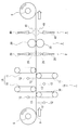
以下、本発明の実施の形態を説明する。ここでは、長尺のMg合金板に研磨を施すMg合金板の研磨方法、およびその後の表面処理方法を説明する。研磨方法は、搬送されるMg合金板に研磨を施す際、研磨液の噴射対象がMg合金板であり、使用する研磨液が、研磨ベルト(研磨材)の幅方向の局所に噴射されることなく、Mg合金板上に噴射されて上記研磨が施されるという方法である。その後の表面処理方法として、洗浄、水切り、乾燥の各工程を施し、Mg合金板は巻き取りロールにて巻き取られ、その全てをインラインで行う。本発明の特徴は、研磨の際、Mg合金板の幅方向全域に研磨液を行き渡らせることで、研磨液の濡れ状態に局所的な差が生じないようにする点にある。以下、研磨方法に上記表面処理方法を含めたものを表面加工方法と称し、図1、2を参照して研磨方法を説明する。その後、表面処理方法、加工対象のMg合金板の順に説明する。
以下、本発明の実施の形態を説明する。ここでは、長尺のMg合金板に研磨を施すMg合金板の研磨方法、およびその後の表面処理方法を説明する。研磨方法は、搬送されるMg合金板に研磨を施す際、研磨液の噴射対象がMg合金板であり、使用する研磨液が、研磨ベルト(研磨材)の幅方向の局所に噴射されることなく、Mg合金板上に噴射されて上記研磨が施されるという方法である。その後の表面処理方法として、洗浄、水切り、乾燥の各工程を施し、Mg合金板は巻き取りロールにて巻き取られ、その全てをインラインで行う。本発明の特徴は、研磨の際、Mg合金板の幅方向全域に研磨液を行き渡らせることで、研磨液の濡れ状態に局所的な差が生じないようにする点にある。以下、研磨方法に上記表面処理方法を含めたものを表面加工方法と称し、図1、2を参照して研磨方法を説明する。その後、表面処理方法、加工対象のMg合金板の順に説明する。
<表面加工方法>
[研磨方法]
研磨工程1では、図1に示すように、繰り出しロールSからMg合金板Pを巻き戻して搬送し、その搬送されたMg合金板Pに研磨を施す。この研磨加工は、Mg合金板Pの表面を、研磨液13の使用下で研磨材により研磨する。研磨材には研磨ベルト1Aを使用する。研磨ベルト1Aの砥粒の粒度は、Mg合金板Pの表面粗さが所望の粗さとなるように適宜選択するとよいが、♯320以上が好ましく、♯400以上、特に♯600以上がより好ましい。後述する所定の表面粗さに研磨することができれば、研磨材の形態は問わない。例えば、ベルト以外でブラシやホイールの砥石などを研磨材に使用しても構わない。
[研磨方法]
研磨工程1では、図1に示すように、繰り出しロールSからMg合金板Pを巻き戻して搬送し、その搬送されたMg合金板Pに研磨を施す。この研磨加工は、Mg合金板Pの表面を、研磨液13の使用下で研磨材により研磨する。研磨材には研磨ベルト1Aを使用する。研磨ベルト1Aの砥粒の粒度は、Mg合金板Pの表面粗さが所望の粗さとなるように適宜選択するとよいが、♯320以上が好ましく、♯400以上、特に♯600以上がより好ましい。後述する所定の表面粗さに研磨することができれば、研磨材の形態は問わない。例えば、ベルト以外でブラシやホイールの砥石などを研磨材に使用しても構わない。
上記所定の表面粗さとは、算術平均粗さRa≦1.2μm、最大高さRmax≦20μm、及び十点平均高さRz≦12μmの少なくとも一つを満たすことである。算術平均粗さRa≦0.6μm、最大高さRmax≦10μm、及び十点平均高さRz≦6μmのうち少なくとも一つを、特に、算術平均粗さRa≦0.3μm、最大高さRmax≦5μm、及び十点平均高さRz≦3μmのうち少なくとも一つを満たすことがより好ましい。
本例では、研磨加工を2段階に分けて施す。その場合、例えば、Mg合金板Pの上流側の研磨ベルト10を♯320(♯400)、下流側の研磨ベルト11を♯400(♯600)のように、2段階の研磨ベルト1Aは、その砥粒の粒度を、上記下流側を上記上流側より細かくするとよい。そうすることで、Mg合金板Pの表面をより均一に平滑に研磨することができる。研磨加工を3段階以上設ける場合であっても、上記2段階の時と同様に、上流側から下流側に向かって砥粒の粒度が細かくなるよう各研磨ベルトを選択するとよい。
研磨加工は、Mg合金板Pの表裏面に対して施す。ここでは、表裏面に設置される研磨ベルト1AはMg合金板Pの長手方向に互いにずれて位置する。Mg合金板Pの表裏面を挟んで研磨ベルト1Aの対向する位置には、基準ロール(図示せず)が設けられている。上記基準ロールを設けることで、Mg合金板Pの表裏面における研磨量をより均等にし易くできる。上記のずれによって、Mg合金板Pの裏面(鉛直下方側)が先に研磨されるように研磨ベルト1Aを設置することが好ましい。上記裏面を先に研磨加工する場合、研磨液13の噴射も上記裏面側が先になるが、研磨液13がMg合金板Pの表面に回り込むことがないので、上記表裏面で研磨液13との接触開始位置を制御し易くなる。研磨ベルト1Aは、Mg合金板Pの表裏面を挟んで対向するように位置してもよい。研磨ベルト1Aによる研磨形式は、Mg合金板Pの搬送方向と同じ方向に回転するダウンカットであることが好ましい。そうすることで、より平滑なMg合金板Pが得られる研磨を施すことができる。但し、研磨効率を求める場合、Mg合金板Pの搬送方向と逆向きに研磨ベルト1Aが回転するアップカットを行っても構わない。特に、研磨効率と研磨面の平滑性との両立を考慮すると、上流側の研磨ベルト10をアップカットとし、下流側の研磨ベルト11をダウンカットとしてもよい。
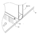
研磨を行う際、上記ダウンカットか、アップカットかによらず、研磨液13は、図2に示すように、研磨ベルト10、11のそれぞれに対してMg合金板Pの上流側に配置されたスプレーノズル12から、研磨ベルト10、11の幅方向(図1に対し、紙面に垂直方向、以下同様)の局所には噴射せず、Mg合金板Pの表面上に噴射される。本例では、Mg合金板Pの幅に対応する長さを有する棒状のスプレーノズル12に複数の噴射口(図示せず)が上記幅方向に等間隔に並んで設けられ、それらの噴射口からMg合金板Pの表面に向かって鉛直下方に線状に噴射する。この場合、Mg合金板Pに達した研磨液13は、Mg合金板Pの幅方向に研磨液13が広がり易い点でより好ましい。また、研磨液13は、研磨ベルト10、11の上流側から鉛直下方よりも研磨ベルト10、11の側のMg合金板Pに向かって傾斜方向に噴射させてもよい。この場合、研磨ベルト10、11とMg合金板Pとの接触箇所付近に研磨液13をより供給し易い。上記各噴射口は、Mg合金板Pの表面上における幅方向全域に研磨液13が行き渡るように、その数、径、および間隔は適宜選択して設けるとよい。例えば、各噴射口は30mm程度の間隔で設けられることが挙げられる。Mg合金板Pに対する研磨液13の噴射位置は、Mg合金板Pと研磨ベルト10、11との接触箇所からおよそ50mmの位置が好適である。そうすることで、Mg合金板Pの表面上で研磨液13が幅方向全体に行き渡るので、研磨焼けの発生を抑制することができる。また、上記のように幅方向全体に研磨液13が行き渡るので、研磨材の目詰まりをも軽減することができる。そのことによって、Mg合金板Pの幅方向に対して、研磨具合に部分的な差が生じず、均一な研磨を施すことができる。その結果、縞模様のないMg合金板Pが得られる。上流側にスプレーノズルを配置すると、研磨によるMg合金板Pと研磨ベルト1Aの摩擦熱および摩擦抵抗を低減することができる。
研磨液13は、スプレーノズル12から、Mg合金板Pの表面の幅方向に隙間なく噴射されてもよい。その場合、スプレーノズル12に拡散ノズル(図示せず)を取り付けた複数の噴射口が、上記幅方向に等間隔に並んで設けられ、それらの噴射口から上記研磨液13がMg合金板Pの表面に向かって噴射されるようにすればよい。
研磨液13は、Mg合金板Pの表面上における幅方向に隙間なく噴射されていてもよいが、隣接する研磨液13の噴射領域同士が、上記研磨ベルト10、11の表面上で一部重複するように噴射されてもよい。その場合、一つの噴射口から噴射される研磨液13のMg合金板Pの表面上における噴射領域の幅をLとすると、その重複している領域、即ち、重複領域は、L×1/2以下であることが好ましい。というのも、研磨液13は、噴射領域の中心部から外側、つまり、隣接する噴射領域に向かって供給密度(単位時間の単位面積当たりにおける研磨液の供給量、以下同様)が減少していく。上記重複領域がL×1/2以下のとき、隣接する二つの噴射領域から一つの重複領域が構成される。つまり、上記重複領域は、上記規定の範囲のとき、研磨液の供給密度が相対的に低い箇所は相対的に高い箇所と重複し、高い箇所は低い箇所と重複する。そのため、上記重複領域は、L×1/2であれば、特に好ましい。したがって、Mg合金板Pの表面の幅方向における研磨液13の噴射状態の差が緩和されて、Mg合金板Pの表面における局所的な目詰まりの発生を抑制することができるので、Mg合金板Pの表面での縞模様の発生をより一層効果的に抑制することができる。
研磨液13が重複するよう、研磨液13は、噴射口から噴射対象(ここでは、Mg合金板P)に到達する間における噴射形状(噴射された研磨液を立体的に三次元で見たときの形状、以下同様)が扁平な三角形であることが好ましい。この場合、研磨液13は、噴射口から上記幅方向に広がりながらMg合金板Pの表面に到達する。つまり、一度に上記幅方向の広範囲を噴射することができる点で好ましい。上記のように、噴射形状が扁平な形状の場合、噴射領域の幅が、上記幅方向に並ぶように噴射されることが好ましい。そうすることで、上記幅方向に隙間なく噴射させやすいうえに、噴射領域同士を重複させやすい。また、その噴射形状が円錐形であってもよい。この場合、上記幅方向のみならず、Mg合金板Pの長手方向(図1に対し、紙面の左右方向)にも広がりながらMg合金板Pの表面に到達する。噴射領域が円形であるので、隣接する噴射領域との重複領域は面で、かつ、広範囲にとることができる点で好ましい。噴射形状が上記のように錐体である場合、噴射領域同士が重複する際に、各重複領域における噴射状態のばらつきが生じないように、研磨液13を噴射するとよい。
研磨液13の流量Q(L/min)は、0.4×10-6/(V1×V2×W)以上であることが好ましく、0.8×10-6/(V1×V2×W)以上、特に1.6×10-6/(V1×V2×W)以上が好ましい。研磨液流量が上記下限値以上であれば、Mg合金板Pの表面を平滑にする場合、研磨焼けの発生を抑制し易い。その研磨液流量は、8.0×10-6/(V1×V2×W)までとする。上記規定の上限値以下であれば、研磨材とMg合金板Pとの間のスリップを起こすことなく研磨を施すことができる。ここで、上記V1はMg合金板Pの搬送速度(m/min)を、上記V2は研磨材の回転速度(m/min)を、WはMg合金板Pの板幅(mm)を示している。
本例のようにダウンカットの場合、上記研磨ベルト10、11のそれぞれの下流側には、スプレーノズル12と同様のスプレーノズルが設けられていなくても構わないが設けることが好ましい。下流側にもスプレーノズルを設ければ、より一層研磨箇所の摩擦抵抗と摩擦熱の低減を図ることができる。下流側のスプレーノズルからは、研磨ベルト10、11に研磨液13を噴射してもよいし、Mg合金板Pの上に噴射してもよい。研磨ベルト10、11に研磨液13を噴射した場合、同ベルトの幅方向における局所的な目詰まりを抑制することができる。また、Mg合金板Pの上に研磨液13を噴射した場合、研磨粉を効率的に洗い流すことができる。一方、アップカットの場合、研磨ベルト10、11の下流側には、スプレーノズルを設置して、その下流側のスプレーノズルからは、研磨ベルト10、11に研磨液13を噴射することが好ましい。そうすることで、研磨によるMg合金板Pと研磨ベルト1Aの摩擦熱および摩擦抵抗を低減することができる。
研磨液13は、研磨によるMg合金板Pと研磨ベルト1Aの摩擦熱および摩擦抵抗を低減するものであれば良い。具体的には、実質的に水のみでも構わない。あるいは研磨粉を排出することができて研磨粉が研磨ベルト1AとMg合金板Pの間に詰まることを抑制し易くするため、水溶性の切削油剤を含むものでも構わない。さらに、Mg合金板Pと反応しにくい研磨液であれば特に好ましい。研磨液13を使用することで、研磨対象がMg合金のように活性な物質であっても研磨粉が粉塵爆発することを防ぐことができる。
{表面処理方法}
上記研磨加工後に、後述する洗浄、水切り、乾燥の各工程を施すことが、Mg合金板表面の腐食の点を考慮すると好ましい。以下、その点について上記各工程を、図1より説明する。
上記研磨加工後に、後述する洗浄、水切り、乾燥の各工程を施すことが、Mg合金板表面の腐食の点を考慮すると好ましい。以下、その点について上記各工程を、図1より説明する。
(洗浄工程)
洗浄工程2では、上記研磨加工を施したMg合金板Pに付着している研磨液13や研磨粉を洗浄液21により洗い流す。本例では、洗浄液21には、水を使用する。この洗浄液21は、研磨液13を洗い流せて、研磨対象と反応し難いものであれば特に問わない。
洗浄工程2では、上記研磨加工を施したMg合金板Pに付着している研磨液13や研磨粉を洗浄液21により洗い流す。本例では、洗浄液21には、水を使用する。この洗浄液21は、研磨液13を洗い流せて、研磨対象と反応し難いものであれば特に問わない。
洗浄工程2では、洗浄液21を吹き出す洗浄ノズル20は、Mg合金板Pの表裏面を挟んで対向する位置に配置できる。そうすることで、Mg合金板Pの表裏面における液体の除去程度に殆ど差が生じることなく研磨液13を洗い流すことができ、研磨ベルト1AのずれによるMg合金板Pの表裏面における液体に接触している時間の差は許容できる。また、研磨ベルト1Aと同様に、Mg合金板Pの表裏面における洗浄ノズル20がMg合金板Pの長手方向にずれて位置していてもよい。そうすれば、表裏面で液体に接触している時間に差が生じ難くすることができる。
(水切り工程)
水切り工程3では、洗浄工程2を経たMg合金板Pに付着している洗浄液21を除去する。洗浄液21の除去には、スポンジ製の水切りロール30のように、十分に洗浄液21を除去することが可能なものを使用することが好適である。その他、洗浄液21を均一に除去することができれば、ゴム製のワイパ、フェルト、圧縮空気を利用したエアナイフ、またはエアカーテンなどが水切り工程3に使用できる。水切りロール30は、Mg合金板Pの幅と同等以上の幅を有していることが好ましい。そうすることで、Mg合金板Pに付着した洗浄液のMg合金板Pにおける幅方向に拭き残しが生じず、均一な拭き取りを行うことができる。
水切り工程3では、洗浄工程2を経たMg合金板Pに付着している洗浄液21を除去する。洗浄液21の除去には、スポンジ製の水切りロール30のように、十分に洗浄液21を除去することが可能なものを使用することが好適である。その他、洗浄液21を均一に除去することができれば、ゴム製のワイパ、フェルト、圧縮空気を利用したエアナイフ、またはエアカーテンなどが水切り工程3に使用できる。水切りロール30は、Mg合金板Pの幅と同等以上の幅を有していることが好ましい。そうすることで、Mg合金板Pに付着した洗浄液のMg合金板Pにおける幅方向に拭き残しが生じず、均一な拭き取りを行うことができる。
水切りロール30は、Mg合金板Pの表裏面を挟んで対向する位置に設置することができる。そうすることで、Mg合金板Pの表裏面における液体の除去程度に差が生じることなく洗浄液21を拭き取ることができるので、表裏面で液体に接触している時間に差が生じ難い。また、上記研磨ベルト1Aと同様に上記洗浄ノズル20がMg合金板Pの長手方向にずれている場合は、Mg合金板Pの表裏面における水切りロール30も同様に長手方向にずれるように設置してもよい。その場合であっても、表裏面で液体に接触している時間に差が生じ難くすることができる。水切り工程3は、3段階以上設けてあっても構わない。そうすることで、より確実に洗浄液21を除去することができる。
(乾燥工程)
乾燥工程4では、水切り工程3後、Mg合金板Pに洗浄液21が残存している可能性があるので、洗浄液21が残存しないように、洗浄液21を乾かす。乾かす手段として、エアブローが好適である。特に40℃以上の温風であればより好ましい。
乾燥工程4では、水切り工程3後、Mg合金板Pに洗浄液21が残存している可能性があるので、洗浄液21が残存しないように、洗浄液21を乾かす。乾かす手段として、エアブローが好適である。特に40℃以上の温風であればより好ましい。
乾燥工程4も、水切り工程3と同様に、Mg合金板Pの表裏面を挟んで対向する位置にエア41を吹き出す送風口40を設置することができる。そうすることで、たとえMg合金板Pの表面に洗浄液21が残存していても、Mg合金板Pの表裏面の同じ位置で乾かすことができるので、表裏面で液体に接触している時間に差が生じ難い。また、上述したように水切りロール30がMg合金板Pの長手方向にずれている場合は、Mg合金板Pの表裏面における送風口40も同様に長手方向にずれるように設置してもよい。その場合であっても、表裏面で液体に接触している時間に差が生じ難くすることができる。
本例では、エアブローは1段階しか設けていないが、より確実に洗浄液21を除去しようとするなら、乾燥工程4を2段階設けておくことが好ましい。その場合、上流側、下流側の少なくとも一方の乾燥工程を40℃以上の温風とすることが乾燥効率の点で好ましい。例えば、上流側のエアの温度を40℃以上とし、下流側のエアの温度を上流側の温度よりも低くすれば、2段階のエアで乾燥の確実性を高めながら、両段階のエアを40℃以上とする場合に比べて乾燥工程4での消費エネルギーを削減できる。
(その他)
上記各工程は、インラインで行われる。例えば、耐食性に優れるMg合金板である場合は、インラインでなくても構わない。但し、インラインの場合、表面加工を手間無く実施することができる点で好ましい。上記各工程が、インラインで行われる際、上記腐食の点を考慮した場合、Mg合金板Pの搬送速度は速い方が好ましい。その場合、その速度は5m/min以上、特に10m/min以上であることがより好ましい。
上記各工程は、インラインで行われる。例えば、耐食性に優れるMg合金板である場合は、インラインでなくても構わない。但し、インラインの場合、表面加工を手間無く実施することができる点で好ましい。上記各工程が、インラインで行われる際、上記腐食の点を考慮した場合、Mg合金板Pの搬送速度は速い方が好ましい。その場合、その速度は5m/min以上、特に10m/min以上であることがより好ましい。
(除液工程)
さらに上記腐食の点を考慮すると、研磨工程1と洗浄工程2の間に、研磨液13を除去するための除液工程を具えていることが好ましい。研磨液13が洗浄液21によって洗い流される前に、例えば、水切り工程3で使用した水切りロール30と同様のスポンジからなる除液ロールで、研磨液13を除去することで、Mg合金板Pの表面が研磨液13に接触している時間を極力短くすることができる。したがって、Mg合金板Pの腐食をより抑えることができる。その他、研磨液13を均一に除去することができれば、ゴム製のワイパ、フェルト、圧縮空気を利用したエアナイフ、またはエアカーテンなどを除液工程に使用してもよい。除液ロールも、Mg合金板Pと同等もしくは同等以上の幅を有していることが好ましい。また、本例のように研磨加工を2段階に分けて施す場合、各段階間、つまり研磨ベルト10と研磨ベルト11の間に上記除液ロールを設けてあると、Mg合金板Pが研磨液13に接触している時間をより一層短くすることができるので好ましい。
さらに上記腐食の点を考慮すると、研磨工程1と洗浄工程2の間に、研磨液13を除去するための除液工程を具えていることが好ましい。研磨液13が洗浄液21によって洗い流される前に、例えば、水切り工程3で使用した水切りロール30と同様のスポンジからなる除液ロールで、研磨液13を除去することで、Mg合金板Pの表面が研磨液13に接触している時間を極力短くすることができる。したがって、Mg合金板Pの腐食をより抑えることができる。その他、研磨液13を均一に除去することができれば、ゴム製のワイパ、フェルト、圧縮空気を利用したエアナイフ、またはエアカーテンなどを除液工程に使用してもよい。除液ロールも、Mg合金板Pと同等もしくは同等以上の幅を有していることが好ましい。また、本例のように研磨加工を2段階に分けて施す場合、各段階間、つまり研磨ベルト10と研磨ベルト11の間に上記除液ロールを設けてあると、Mg合金板Pが研磨液13に接触している時間をより一層短くすることができるので好ましい。
<被加工材>
上記の表面加工方法を施すMg合金板Pは、鋳造より得られたものに圧延を施したものが好適である。その他に、鋳造材、圧延材にレベラー加工を施したもの、を被加工材としてもよい。それらの被加工材は、圧延前に溶体化処理を施しておいても構わない。
上記の表面加工方法を施すMg合金板Pは、鋳造より得られたものに圧延を施したものが好適である。その他に、鋳造材、圧延材にレベラー加工を施したもの、を被加工材としてもよい。それらの被加工材は、圧延前に溶体化処理を施しておいても構わない。
[形状]
本例では、コイル状に巻き取った長尺のMg合金板Pを使用するが、特に加工対象に関して限定はされないので、例えば、短尺板であってもよい。例えば、コイルにするなら、連続鋳造で、短尺板なら、ダイカストなどで成形するとよい。また、長尺板を必要サイズにカットして短尺板を作製してもよい。
本例では、コイル状に巻き取った長尺のMg合金板Pを使用するが、特に加工対象に関して限定はされないので、例えば、短尺板であってもよい。例えば、コイルにするなら、連続鋳造で、短尺板なら、ダイカストなどで成形するとよい。また、長尺板を必要サイズにカットして短尺板を作製してもよい。
[組成]
Mg合金板Pは、Mgに種々の元素を添加したものが挙げられる。添加元素は、例えば、Al、Zn、Mn、Si、Cu、Ag、Y、Zrなどの元素群のうち少なくとも一種の元素が挙げられる。上記元素群から選択される複数の元素を含有していてもよい。具体的には、ASTM規格におけるAZ系なら例えばAZ31、AZ61、AZ91などを、AM系なら例えばAM60などを、その他、AS系、ZK系などのMg合金を利用することができる。特に、Alを7質量%~12質量%含有するMg合金系は耐食性が高く、高強度である点で好適である。したがって、粘り気が少なく、研磨粉が研磨材に付着しにくいため、上記目詰まりのばらつきを防止しやすくなる。
Mg合金板Pは、Mgに種々の元素を添加したものが挙げられる。添加元素は、例えば、Al、Zn、Mn、Si、Cu、Ag、Y、Zrなどの元素群のうち少なくとも一種の元素が挙げられる。上記元素群から選択される複数の元素を含有していてもよい。具体的には、ASTM規格におけるAZ系なら例えばAZ31、AZ61、AZ91などを、AM系なら例えばAM60などを、その他、AS系、ZK系などのMg合金を利用することができる。特に、Alを7質量%~12質量%含有するMg合金系は耐食性が高く、高強度である点で好適である。したがって、粘り気が少なく、研磨粉が研磨材に付着しにくいため、上記目詰まりのばらつきを防止しやすくなる。
<作用効果>
上述した実施形態1に係るMg合金板の研磨方法によれば、Mg合金板の表面を平滑に湿式研磨した場合、Mg合金板の幅方向における研磨液の濡れ状態に差が生じることを抑制することができるので、研磨焼けを生じさせず、さらに、研磨ベルトの目詰まりのばらつきを抑制されるので、Mg合金板の表面での縞模様の発生を生じ難くすることができる。したがって、金属質感の高いMg合金板を得易い。
上述した実施形態1に係るMg合金板の研磨方法によれば、Mg合金板の表面を平滑に湿式研磨した場合、Mg合金板の幅方向における研磨液の濡れ状態に差が生じることを抑制することができるので、研磨焼けを生じさせず、さらに、研磨ベルトの目詰まりのばらつきを抑制されるので、Mg合金板の表面での縞模様の発生を生じ難くすることができる。したがって、金属質感の高いMg合金板を得易い。
<<実施形態2>>
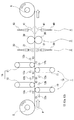
次に、実施形態2に係るMg合金板に施す研磨方法を図3~5に基づいて説明する。本例の研磨方法は、搬送されるMg合金板に研磨を施す際、研磨液の噴射対象が研磨材であり、研磨材の表面に複数の噴射領域が研磨材の幅方向に隙間なく形成されるように研磨液を噴射する点が実施形態1の研磨方法と相違する。その後の表面処理方法は、上述した実施形態1と同様である。以下、実施形態1と相違する点を中心に説明する。
次に、実施形態2に係るMg合金板に施す研磨方法を図3~5に基づいて説明する。本例の研磨方法は、搬送されるMg合金板に研磨を施す際、研磨液の噴射対象が研磨材であり、研磨材の表面に複数の噴射領域が研磨材の幅方向に隙間なく形成されるように研磨液を噴射する点が実施形態1の研磨方法と相違する。その後の表面処理方法は、上述した実施形態1と同様である。以下、実施形態1と相違する点を中心に説明する。
[研磨方法]
研磨工程1では、図3に示すように、繰り出しロールSからMg合金板Pを巻き戻して搬送し、その搬送されたMg合金板Pに研磨を施す。
研磨工程1では、図3に示すように、繰り出しロールSからMg合金板Pを巻き戻して搬送し、その搬送されたMg合金板Pに研磨を施す。
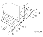
研磨を行う際、研磨液13は、図3、4に示すように、研磨ベルト10、11のそれぞれに対してMg合金板Pの上流側及び下流側に配置されたスプレーノズル12から、研磨液13が、研磨ベルト10、11の幅方向(図3に対し、紙面に鉛直方向、以下同様)に隙間なく噴射される。本例では、研磨ベルト1Aの幅に対応する長さを有する棒状のスプレーノズル12に、拡散ノズル14を取り付けた複数の噴射口が、上記幅方向に等間隔に並んで設けられ、それらの噴射口から研磨液13が研磨ベルト1Aの表面に向かって噴射される。この研磨液13は、研磨ベルト10、11に向かって、Mg合金板Pと平行になるように噴射されてもよいし、Mg合金板P側に傾斜する俯角に噴射されてもよい。前者の場合、研磨ベルト10、11の幅方向に研磨液が広がり易い点で好ましく、後者の場合、研磨ベルト10、11とMg合金板Pとの接触箇所に研磨液をより供給し易い点で好ましい。また、研磨ベルト10、11の走行に伴って、Mg合金板Pと研磨ベルト10、11との間に研磨液13を引き込む側に設けられたスプレーノズルをメイン、その反対側に設けられたスプレーノズルをサブとする。よって、ダウンカット(アップカット)において上流側(下流側)をメイン、下流側(上流側)をサブとし、ダウンカット(アップカット)において、上流側(下流側)にメインスプレーノズル12aを設けることにより、研磨によるMg合金板Pと研磨ベルト10、11の摩擦熱および摩擦抵抗を低減することも勿論できる。また、上記噴射口の数や各噴射口同士の間隔は、研磨液13を研磨材の表面全域に行き渡るように、後述する噴射領域の重複領域や噴射形状により適宜選択するとよい。
研磨液13は、研磨ベルト10、11の表面上における幅方向に隙間なく噴射されていれば構わないが、本例のように、隣接する研磨液13の噴射領域同士が、上記研磨ベルト10、11の表面上で一部重複するように噴射されることが好ましい。図5に示すように、一つの噴射口から噴射される研磨液13の研磨ベルト10、11の表面上における噴射領域の幅をLとすると、その重複している領域、即ち、重複領域は、L×1/2以下であることが好ましい。というのも、研磨液13は、噴射領域の中心部から外側、つまり、隣接する噴射領域に向かって供給密度(単位時間の単位面積当たりにおける研磨液の供給量、以下同様)が減少していく。重複領域がL×1/2以下のとき、隣接する二つの噴射領域から一つの重複領域が構成される。つまり、その重複領域は、上記規定の範囲のとき、研磨液の供給密度が相対的に低い箇所は相対的に高い箇所と重複し、高い箇所は低い箇所と重複する。そのため、上記重複領域は、L×1/2であれば、特に好ましい。したがって、研磨ベルト10、11の表面の幅方向における研磨液13の噴射状態の差が緩和されて、研磨ベルト10、11の表面における局所的な目詰まりの発生を抑制することができるので、Mg合金板Pの表面での縞模様の発生をより一層効果的に抑制することができる。
上記のように研磨液13が重複するよう、研磨液13は、噴射口から上記研磨ベルト10、11に到達する間における噴射形状(噴射された研磨液を立体的に三次元で見たときの形状、以下同様)が扁平な三角形であることが好ましい。この場合、研磨液13は、噴射口から上記幅方向に広がりながら研磨ベルト10、11の表面に到達する。つまり、一度に上記幅方向の広範囲を噴射することができる点で好ましい。上記のように、噴射形状が扁平な形状の場合、噴射領域の幅が、上記幅方向に並ぶように噴射されることが好ましい。そうすることで、上記幅方向に隙間なく噴射させやすいうえに、噴射領域同士を重複させやすい。また、その噴射形状が円錐形であってもよい。この場合、研磨液13は上記幅方向のみならず、研磨ベルト1Aの長手方向(図3に対し、Mg合金板Pに鉛直方向)にも広がりながら同ベルトの表面に到達する。噴射領域が円形であれば、隣接する噴射領域との重複領域は面で、かつ、広範囲にとることができる点で好ましい。噴射形状が上記のように錐体である場合、噴射領域同士が重複する際に、各重複領域における噴射状態のばらつきが生じないように、研磨液13を噴射するとよい。
ダウンカット(アップカット)の場合、上記研磨ベルト10、11のそれぞれの下流側(上流側)においては、サブスプレーノズル12bが設けられていなくても構わない。但し、図3や4のように、ダウンカット(アップカット)では、下流側(上流側)にサブスプレーノズル12bを設けることが、より一層研磨箇所の摩擦抵抗と摩擦熱の低減を図ることができる点で好ましい。サブスプレーノズル12bを設ける場合、そのノズルからの研磨液の噴射態様は、メインスプレーノズル12aと異なる態様でも構わない。例えば、下流側(上流側)のサブスプレーノズル12bからは、Mg合金板Pの上に研磨液13を噴射してもよい。そうすることで、研磨粉を効率的に洗い流すことができる。つまり、研磨ベルト10、11やMg合金板Pの表面のいずれにサブスプレーノズル12bから研磨液13を噴射するにせよ、研磨液13の噴射領域同士に、隙間があっても構わないし、噴射領域同士が重複していなくても構わない。また、研磨液13の噴射形状が、扁平な三角形や円錐形でなく円柱形などであっても構わない。但し、上記で述べたように、ダウンカット(アップカット)における下流側(上流側)であっても、(1)上記隙間はない方が、(2)上記噴射領域同士は重複している方が、(3)上記噴射形状は扁平な三角形や円錐形などの立体形である方が好ましい。
<作用効果>
上述した実施形態に係るMg合金板の研磨方法によれば、Mg合金板の表面を平滑に湿式研磨した場合、研磨ベルトの幅方向に対する研磨液の噴射状態のばらつきを緩和することができるので、研磨ベルトの表面における局所的な目詰まりの発生を抑制することができる。したがって、Mg合金板の表面での縞模様の発生を抑制することができるので、金属質感に優れるMg合金板を得易い。
上述した実施形態に係るMg合金板の研磨方法によれば、Mg合金板の表面を平滑に湿式研磨した場合、研磨ベルトの幅方向に対する研磨液の噴射状態のばらつきを緩和することができるので、研磨ベルトの表面における局所的な目詰まりの発生を抑制することができる。したがって、Mg合金板の表面での縞模様の発生を抑制することができるので、金属質感に優れるMg合金板を得易い。
<試験例1>
試験例1として、Mg合金板Pをコイル状に巻いたものを用意し、そのMg合金板Pを図1に示す表面加工方法の手順で、研磨ベルトにおける砥粒を様々な粒度、及び、様々な研磨液流量で研磨加工を施した。研磨加工後、表面処理方法を施してから巻き取りロールEにて巻き取られたMg合金板Pの表面粗さを測定した。そして、Mg合金板Pの表面を目視し、研磨焼けや縞模様の発生具合を比較した。
試験例1として、Mg合金板Pをコイル状に巻いたものを用意し、そのMg合金板Pを図1に示す表面加工方法の手順で、研磨ベルトにおける砥粒を様々な粒度、及び、様々な研磨液流量で研磨加工を施した。研磨加工後、表面処理方法を施してから巻き取りロールEにて巻き取られたMg合金板Pの表面粗さを測定した。そして、Mg合金板Pの表面を目視し、研磨焼けや縞模様の発生具合を比較した。
加工対象として、Mg合金板Pは、Mg-9.0質量%Al-1.0質量%Znを含有するAZ91相当の組成を持ち、双ロール連続鋳造より製造されたMg合金板を、コイル状に巻き取ったものを使用する。そのMg合金コイルに、以下に示す表面加工条件で表面加工を施す。その際、研磨ベルトにおける砥粒の粒度および研磨液流量を種々変更して、試料1~16を作製した。但し、試料1~9、13~16は、図1のようにMg合金板P上に、試料10~12は、Mg合金板Pではなく、図1の研磨ベルト1Aに対し、その幅方向の一部に研磨液13を噴射した。
[[表面加工条件]]
研磨方法:湿式ベルト研磨
砥粒の最終番手:試料No.1、4、7、10、13-♯320
試料No.2、5、8、11、14-♯400
試料No.3、6、9、12、15-♯600
試料No.16-♯240
研磨液流量:試料No.1~3-0.4×10⁻⁶/(V1×V2×W)
試料No.4~6-0.8×10⁻⁶/(V1×V2×W)
試料No.7~12-1.6×10⁻⁶/(V1×V2×W)
試料No.13~16-0.3×10⁻⁶/(V1×V2×W)
Mg合金板の搬送速度V1:5m/min
研磨ベルトの周速V2:1200m/min
Mg合金板の幅W:200mm
研磨液の温度:40℃
洗浄液の温度:40℃
乾燥工程:40℃のエアブロー
研磨方法:湿式ベルト研磨
砥粒の最終番手:試料No.1、4、7、10、13-♯320
試料No.2、5、8、11、14-♯400
試料No.3、6、9、12、15-♯600
試料No.16-♯240
研磨液流量:試料No.1~3-0.4×10⁻⁶/(V1×V2×W)
試料No.4~6-0.8×10⁻⁶/(V1×V2×W)
試料No.7~12-1.6×10⁻⁶/(V1×V2×W)
試料No.13~16-0.3×10⁻⁶/(V1×V2×W)
Mg合金板の搬送速度V1:5m/min
研磨ベルトの周速V2:1200m/min
Mg合金板の幅W:200mm
研磨液の温度:40℃
洗浄液の温度:40℃
乾燥工程:40℃のエアブロー
その後、試料1~16の表面粗さを測定し、その表面を観察した。その結果を表1に示す。この表における○の表記は、研磨焼けがなく、縞模様もない金属質感に優れた表面であるという意味を表す。

<結果>
表面加工後、試料No.1、4、5、7~9、16は、その表面に研磨焼けや縞模様の発生は見られなかった。試料No.2、3、6、13~15は、その表面に研磨焼けが発生した。これは、表面粗さが平滑な割に研磨液流量が十分でなく、研磨焼けが発生する結果となったと考えられる。試料No.10~12は、縞模様がそれぞれ発生した。これは、研磨ベルトに局所的に研磨液を噴射したことで、研磨液が幅方向に十分に行き渡らなかったために、研磨ベルトの幅方向における局所的な目詰まりを解消できなかったからと考えられる。その結果、研磨具合にMg合金板の幅方向で差が生じ、縞模様の発生を抑制できなかった。表面粗さを測定したところ、同じ表面粗さ同士では、研磨液流量が多いほど、研磨焼けは発生せず、また、表面粗さが平滑になるほど、研磨液流量を多く必要とすることがわかった。一方、研磨液の噴射箇所を見てみると、研磨液流量を多くしても、研磨液を研磨材に噴射した場合は、縞模様が発生してしまうことがわかった。
表面加工後、試料No.1、4、5、7~9、16は、その表面に研磨焼けや縞模様の発生は見られなかった。試料No.2、3、6、13~15は、その表面に研磨焼けが発生した。これは、表面粗さが平滑な割に研磨液流量が十分でなく、研磨焼けが発生する結果となったと考えられる。試料No.10~12は、縞模様がそれぞれ発生した。これは、研磨ベルトに局所的に研磨液を噴射したことで、研磨液が幅方向に十分に行き渡らなかったために、研磨ベルトの幅方向における局所的な目詰まりを解消できなかったからと考えられる。その結果、研磨具合にMg合金板の幅方向で差が生じ、縞模様の発生を抑制できなかった。表面粗さを測定したところ、同じ表面粗さ同士では、研磨液流量が多いほど、研磨焼けは発生せず、また、表面粗さが平滑になるほど、研磨液流量を多く必要とすることがわかった。一方、研磨液の噴射箇所を見てみると、研磨液流量を多くしても、研磨液を研磨材に噴射した場合は、縞模様が発生してしまうことがわかった。
以上より、研磨加工の際に、研磨液をMg合金板上の幅方向に均一に行き渡らせなければ、研磨焼けが、また、研磨材の目詰まりのばらつきを解消しなければ、縞模様がそれぞれ発生することがわかり、本発明の研磨方法を施せば、その研磨焼けおよび縞模様は生じ難いことが判明した。特に、表面をより平滑に、研磨液流量をより多く使用することで研磨焼けが生じず、縞模様のない金属質感に優れたMg合金板が得られることが判明した。このような結果となった理由は、本発明の研磨方法では、研磨液をMg合金板の幅方向全体に均一に行き渡らせることで、Mg合金板表面の幅方向全域における研磨液の濡れ状態に局所的な差が生じなかったためである。その結果、研磨材の目詰まりがその表面で局所的に発生するのを抑制し、研磨具合に上記幅方向で局所的に差が生じず、Mg合金板の幅方向全域に均一に研磨を施すことができたからであると考えられる。
<試験例2>
試験例2として、Mg合金板Pをコイル状に巻いたものを用意し、そのMg合金板Pを図3に示す表面加工方法の手順で、研磨ベルトにおける砥粒を様々な粒度、及び、様々な研磨液の噴射形状で研磨加工を施した。研磨加工後、表面処理方法を施してから巻き取りロールEにて巻き取られたMg合金板Pの表面粗さを測定した。そして、Mg合金板Pの表面を目視し、縞模様の発生具合を比較した。
試験例2として、Mg合金板Pをコイル状に巻いたものを用意し、そのMg合金板Pを図3に示す表面加工方法の手順で、研磨ベルトにおける砥粒を様々な粒度、及び、様々な研磨液の噴射形状で研磨加工を施した。研磨加工後、表面処理方法を施してから巻き取りロールEにて巻き取られたMg合金板Pの表面粗さを測定した。そして、Mg合金板Pの表面を目視し、縞模様の発生具合を比較した。
加工対象として、Mg合金板Pは、Mg-9.0質量%Al-1.0質量%Znを含有するAZ91相当の組成を持ち、双ロール連続鋳造より製造されたMg合金板を、コイル状に巻き取ったものを使用する。そのMg合金コイルに、以下に示す表面加工条件で表面加工を施す。その際、研磨ベルトにおける砥粒の粒度および研磨液の重複領域を種々変更して、試料1~18を作製した。但し、試料1~3は、重複領域はなしで隙間もなし、試料4~6は、重複領域が噴射領域の1/4倍、試料7~12は、重複領域が噴射領域の1/2倍、試料13~15は、重複領域なしで隙間が噴射領域の5倍、試料16~18は重複領域なしで隙間が噴射領域の1/4倍、とする。なお、各噴射領域同士に隙間がある試料は、下記の表2の重複領域の欄において、-(マイナス)で表す。
[[表面加工条件]]
研磨方法:湿式ベルト研磨
砥粒の最終番手:試料1、4、7、10、13、16-♯320
試料2、5、8、11、14、17-♯400
試料3、6、9、12、15、18-♯600
研磨液の噴射形状:試料1~9、16~18-三角形
試料10~12-円錐形
試料13~15-円柱形
Mg合金板の搬送速度:5m/min
研磨ベルトの周速:1200m/min
Mg合金板の幅:200mm
研磨液の温度:40℃
洗浄液の温度:40℃
乾燥工程:40℃のエアブロー
研磨方法:湿式ベルト研磨
砥粒の最終番手:試料1、4、7、10、13、16-♯320
試料2、5、8、11、14、17-♯400
試料3、6、9、12、15、18-♯600
研磨液の噴射形状:試料1~9、16~18-三角形
試料10~12-円錐形
試料13~15-円柱形
Mg合金板の搬送速度:5m/min
研磨ベルトの周速:1200m/min
Mg合金板の幅:200mm
研磨液の温度:40℃
洗浄液の温度:40℃
乾燥工程:40℃のエアブロー
その後、試料1~18の表面粗さを測定し、その表面を観察した。その結果を表2に示す。この表における○の表記は、縞模様がない金属質感に優れた表面であり、×の表記は、縞模様が生じたという意味を表す。
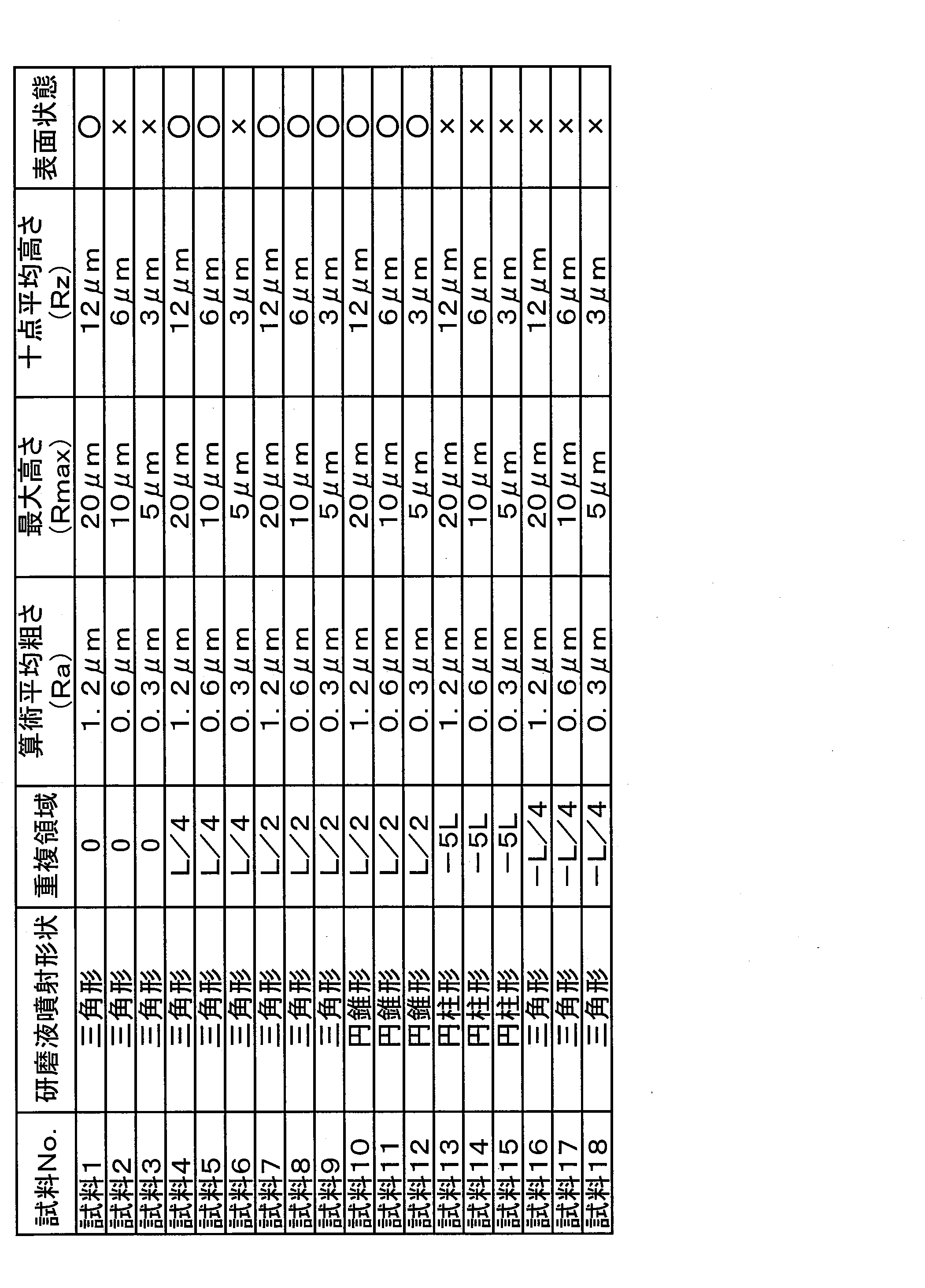
<結果>
表面加工後、試料1、4、5、7~12は、その表面に縞模様の発生は見られなかった。試料2、3、6、13~18は、その表面に縞模様が発生した。試料2、3、6に関しては、表面が平滑な割に研磨液の重複領域が十分でなく、縞模様が発生する結果となったと考えられる。試料13~18に関しては、研磨液の噴射領域が重複しておらず、研磨材の表面における幅方向に対する研磨液の噴射状態にばらつきが生じた。その結果、研磨材における目詰まりが研磨材表面に局所的に生じ、Mg合金板上で研磨具合の部分的な差が生じたからであると考えられる。Mg合金板の表面粗さを測定したところ、同じ表面粗さ同士では、研磨液の重複領域が広いほど、縞模様が発生せず、また、表面が平滑になるほど、研磨液の重複領域を広くする必要があることがわかった。
表面加工後、試料1、4、5、7~12は、その表面に縞模様の発生は見られなかった。試料2、3、6、13~18は、その表面に縞模様が発生した。試料2、3、6に関しては、表面が平滑な割に研磨液の重複領域が十分でなく、縞模様が発生する結果となったと考えられる。試料13~18に関しては、研磨液の噴射領域が重複しておらず、研磨材の表面における幅方向に対する研磨液の噴射状態にばらつきが生じた。その結果、研磨材における目詰まりが研磨材表面に局所的に生じ、Mg合金板上で研磨具合の部分的な差が生じたからであると考えられる。Mg合金板の表面粗さを測定したところ、同じ表面粗さ同士では、研磨液の重複領域が広いほど、縞模様が発生せず、また、表面が平滑になるほど、研磨液の重複領域を広くする必要があることがわかった。
なお、上述した実施の形態は、本発明の要旨を逸脱することなく、適宜変更することが可能であり、上述した構成に限定されるものではない。例えば、Mg合金板と研磨ベルト(研磨材)の双方に研磨液を噴射してもよい。具体的には、研磨形式がダウンカットか、アップカットかによらず、研磨ベルトの上流側に研磨ベルトとMg合金板との両方に研磨液を噴射するスプレーノズルを配置してもよい。或いは、研磨ベルトの上流側に研磨ベルトに研磨液を噴射するスプレーノズルと、Mg合金板表面に研磨液を噴射するスプレーノズルとを並置してもよい。研磨形式がアップカットの場合は、Mg合金板表面に研磨液を噴射するスプレーノズルを上記上流側に配置し、研磨ベルトに研磨液を噴射するスプレーノズルを上記下流側にそれぞれ配置してもよい。
本発明のMg合金板の研磨方法は、Mg合金板の表面を平滑に湿式研磨する際に利用することができる。
S 繰り出しロール
P Mg合金板
1 研磨工程 1A、10、11 研磨ベルト
12 スプレーノズル
12a メインスプレーノズル 12b サブスプレーノズル
13 研磨液
14 拡散ノズル
2 洗浄工程 20 洗浄ノズル 21 洗浄液
3 水切り工程 30 水切りロール
4 乾燥工程 40 送風口 41 エア
E 巻き取りロール
P Mg合金板
1 研磨工程 1A、10、11 研磨ベルト
12 スプレーノズル
12a メインスプレーノズル 12b サブスプレーノズル
13 研磨液
14 拡散ノズル
2 洗浄工程 20 洗浄ノズル 21 洗浄液
3 水切り工程 30 水切りロール
4 乾燥工程 40 送風口 41 エア
E 巻き取りロール
Claims (17)
- 搬送されるマグネシウム合金板の表面を、研磨液の使用下で研磨材により研磨する研磨工程を具えるマグネシウム合金板の研磨方法であって、
前記研磨液を、前記マグネシウム合金板上、および前記研磨材の表面の少なくとも一方の噴射対象に噴射し、
前記噴射は、少なくとも前記マグネシウム合金板と研磨材との接触箇所において、前記噴射対象の幅方向全域に前記研磨液を行き渡らせるように行うことを特徴とするマグネシウム合金板の研磨方法。 - 前記噴射対象が、前記マグネシウム合金板であり、
前記研磨液が、前記研磨材の幅方向の局所に噴射されることなく、前記マグネシウム合金板上に噴射されることを特徴とする請求項1に記載のマグネシウム合金板の研磨方法。 - 前記マグネシウム合金板の搬送速度をV1(m/min)、前記研磨材の回転速度をV2(m/min)、前記マグネシウム合金板の板幅をW(mm)とすると、前記研磨液の流量Q(L/min)は、0.4×10-6/(V1×V2×W)以上であることを特徴とする請求項2に記載のマグネシウム合金板の研磨方法。
- 前記流量Q(L/min)は、0.8×10-6/(V1×V2×W)以上であることを特徴とする請求項3に記載のマグネシウム合金板の研磨方法。
- 前記流量Q(L/min)は、1.6×10-6/(V1×V2×W)以上であることを特徴とする請求項3に記載のマグネシウム合金板の研磨方法。
- 前記マグネシウム合金板の表面に複数の噴射領域が形成されるように、前記研磨液を噴射することを特徴とする請求項2に記載のマグネシウム合金板の研磨方法。
- 前記マグネシウム合金板の表面に複数の噴射領域がマグネシウム合金板の幅方向に隙間なく形成されるように、前記研磨液を噴射することを特徴とする請求項2に記載のマグネシウム合金板の研磨方法。
- 前記噴射対象が、前記研磨材であり、
前記研磨材の表面に複数の噴射領域が研磨材の幅方向に隙間なく形成されるように前記研磨液を噴射することを特徴とする請求項1に記載のマグネシウム合金板の研磨方法。 - 隣接する各噴射領域同士が前記幅方向に一部重複するように、前記研磨液を噴射することを特徴とする請求項7または8に記載のマグネシウム合金板の研磨方法。
- さらに、前記噴射により重複する領域を重複領域とし、前記噴射領域における前記幅方向の長さをLとすると、
前記重複領域における前記幅方向の長さが、L×1/2以下であることを特徴とする請求項9に記載のマグネシウム合金板の研磨方法。 - 前記研磨液の前記噴射対象まで到達する間における噴射形状が扁平な三角形であることを特徴とする請求項2、6~10のいずれか1項に記載のマグネシウム合金板の研磨方法。
- 前記研磨液の前記噴射対象まで到達する間における噴射形状が円錐形であることを特徴とする請求項2、6~10のいずれか1項に記載のマグネシウム合金板の研磨方法。
- 前記マグネシウム合金板の表面粗さが、算術平均粗さRa≦1.2μm、最大高さRmax≦20μm、及び十点平均高さRz≦12μmの少なくとも一つを満たすように研磨することを特徴とする請求項1~12のいずれか1項に記載のマグネシウム合金板の研磨方法。
- 前記表面粗さが、算術平均粗さRa≦0.6μm、最大高さRmax≦10μm、及び十点平均高さRz≦6μmの少なくとも一つを満たすことを特徴とする請求項13に記載のマグネシウム合金板の研磨方法。
- 前記表面粗さが、算術平均粗さRa≦0.3μm、最大高さRmax≦5μm、及び十点平均高さRz≦3μmの少なくとも一つを満たすことを特徴とする請求項13に記載のマグネシウム合金板の研磨方法。
- 請求項1~15のいずれか1項に記載のマグネシウム合金板の研磨方法によって製造されたことを特徴とするマグネシウム合金板。
- 前記マグネシウム合金板は、アルミニウムを7質量%以上12質量%以下含有するマグネシウム合金からなることを特徴とする請求項16に記載のマグネシウム合金板。
Applications Claiming Priority (4)
| Application Number | Priority Date | Filing Date | Title |
|---|---|---|---|
| JP2010043591A JP2011177823A (ja) | 2010-02-26 | 2010-02-26 | マグネシウム合金板の研磨方法およびマグネシウム合金板 |
| JP2010-043590 | 2010-02-26 | ||
| JP2010-043591 | 2010-02-26 | ||
| JP2010043590A JP2011177822A (ja) | 2010-02-26 | 2010-02-26 | マグネシウム合金板の研磨方法およびマグネシウム合金板 |
Publications (1)
| Publication Number | Publication Date |
|---|---|
| WO2011105302A1 true WO2011105302A1 (ja) | 2011-09-01 |
Family
ID=44506714
Family Applications (1)
| Application Number | Title | Priority Date | Filing Date |
|---|---|---|---|
| PCT/JP2011/053563 Ceased WO2011105302A1 (ja) | 2010-02-26 | 2011-02-18 | マグネシウム合金板の研磨方法およびマグネシウム合金板 |
Country Status (2)
| Country | Link |
|---|---|
| TW (1) | TW201201958A (ja) |
| WO (1) | WO2011105302A1 (ja) |
Cited By (3)
| Publication number | Priority date | Publication date | Assignee | Title |
|---|---|---|---|---|
| CN102303274A (zh) * | 2011-09-09 | 2012-01-04 | 山东浩器生物装备技术有限公司 | 真空冷冻干燥机板层表面处理工艺 |
| CN110052929A (zh) * | 2019-04-12 | 2019-07-26 | 浙江科特汽配有限公司 | 一种离合器面片正反一次性磨削机构装置 |
| CN110281117A (zh) * | 2019-08-02 | 2019-09-27 | 天津丹阳车圈有限公司 | 一种直传式车圈侧面打磨装置 |
Families Citing this family (1)
| Publication number | Priority date | Publication date | Assignee | Title |
|---|---|---|---|---|
| CN103128633B (zh) * | 2013-02-21 | 2015-12-09 | 宁夏丰兆科技发展有限公司 | 镁板抛光机 |
Citations (7)
| Publication number | Priority date | Publication date | Assignee | Title |
|---|---|---|---|---|
| JPH08243907A (ja) * | 1995-03-08 | 1996-09-24 | Nisshin Steel Co Ltd | ヘアライン仕上げ金属帯の製造方法および装置 |
| JP2002046065A (ja) * | 2000-08-07 | 2002-02-12 | Hoya Corp | 研磨装置及び研磨方法、並びに磁気記録媒体用ガラス基板及び磁気記録媒体の製造方法 |
| JP2002052857A (ja) * | 2000-08-14 | 2002-02-19 | Fuji Photo Film Co Ltd | 平版印刷版用金属板の粗面化装置、平版印刷版用金属板の粗面化方法、及びps版 |
| JP2002137151A (ja) * | 2000-10-31 | 2002-05-14 | Okamoto Machine Tool Works Ltd | マグネシウム合金製ワ−クの加工方法 |
| JP2005074542A (ja) * | 2003-08-29 | 2005-03-24 | Itochu Corp | マグネシウム帯板用面削装置 |
| JP2005272923A (ja) * | 2004-03-24 | 2005-10-06 | Arrk Okayama Co Ltd | マグネシウム又はマグネシウム合金からなる製品及びその製造方法 |
| JP2006095649A (ja) * | 2004-09-29 | 2006-04-13 | Daido Steel Co Ltd | 表面欠陥が少ないマグネシウム合金コイルの製造方法 |
-
2011
- 2011-02-18 WO PCT/JP2011/053563 patent/WO2011105302A1/ja not_active Ceased
- 2011-02-25 TW TW100106394A patent/TW201201958A/zh unknown
Patent Citations (7)
| Publication number | Priority date | Publication date | Assignee | Title |
|---|---|---|---|---|
| JPH08243907A (ja) * | 1995-03-08 | 1996-09-24 | Nisshin Steel Co Ltd | ヘアライン仕上げ金属帯の製造方法および装置 |
| JP2002046065A (ja) * | 2000-08-07 | 2002-02-12 | Hoya Corp | 研磨装置及び研磨方法、並びに磁気記録媒体用ガラス基板及び磁気記録媒体の製造方法 |
| JP2002052857A (ja) * | 2000-08-14 | 2002-02-19 | Fuji Photo Film Co Ltd | 平版印刷版用金属板の粗面化装置、平版印刷版用金属板の粗面化方法、及びps版 |
| JP2002137151A (ja) * | 2000-10-31 | 2002-05-14 | Okamoto Machine Tool Works Ltd | マグネシウム合金製ワ−クの加工方法 |
| JP2005074542A (ja) * | 2003-08-29 | 2005-03-24 | Itochu Corp | マグネシウム帯板用面削装置 |
| JP2005272923A (ja) * | 2004-03-24 | 2005-10-06 | Arrk Okayama Co Ltd | マグネシウム又はマグネシウム合金からなる製品及びその製造方法 |
| JP2006095649A (ja) * | 2004-09-29 | 2006-04-13 | Daido Steel Co Ltd | 表面欠陥が少ないマグネシウム合金コイルの製造方法 |
Cited By (3)
| Publication number | Priority date | Publication date | Assignee | Title |
|---|---|---|---|---|
| CN102303274A (zh) * | 2011-09-09 | 2012-01-04 | 山东浩器生物装备技术有限公司 | 真空冷冻干燥机板层表面处理工艺 |
| CN110052929A (zh) * | 2019-04-12 | 2019-07-26 | 浙江科特汽配有限公司 | 一种离合器面片正反一次性磨削机构装置 |
| CN110281117A (zh) * | 2019-08-02 | 2019-09-27 | 天津丹阳车圈有限公司 | 一种直传式车圈侧面打磨装置 |
Also Published As
| Publication number | Publication date |
|---|---|
| TW201201958A (en) | 2012-01-16 |
Similar Documents
| Publication | Publication Date | Title |
|---|---|---|
| EP3251765B1 (en) | Method and device for descaling metal wire | |
| KR101804834B1 (ko) | 압연 롤의 세정 장치 및 세정 방법 | |
| JP5515593B2 (ja) | ワイヤーソーによるシリコンインゴットの切断方法およびワイヤーソー | |
| JP6249929B2 (ja) | 鋼線材の連続表面処理方法 | |
| WO2011105302A1 (ja) | マグネシウム合金板の研磨方法およびマグネシウム合金板 | |
| KR101558196B1 (ko) | 잉곳 절단 장치 및 절단 방법 | |
| JPWO2011105181A1 (ja) | マグネシウム合金板の表面加工方法およびマグネシウム合金板 | |
| JP2012055955A (ja) | 冷間圧延における圧延潤滑方法およびその装置 | |
| CN107052045A (zh) | 用于电火花纹理化板材的压纹 | |
| KR101105920B1 (ko) | 연속주조기의 주조 벨트의 표면 집합조직 | |
| JP2011177823A (ja) | マグネシウム合金板の研磨方法およびマグネシウム合金板 | |
| JP2011177822A (ja) | マグネシウム合金板の研磨方法およびマグネシウム合金板 | |
| JP2011255388A (ja) | 高温鋳片のスケール除去装置 | |
| US20080216925A1 (en) | Method and apparatus for producing scale-free sheet metal | |
| JP2007050440A (ja) | 銅線の製造方法および銅線の製造装置 | |
| JP4418224B2 (ja) | 溶接スパッタの除去方法 | |
| JP2010131697A (ja) | 熱間スラブの表面手入れ方法 | |
| JP4234827B2 (ja) | 金属ストリップ鋳造方法、金属ストリップを鋳造するストリップ鋳造装置、及び双ロールストリップ鋳造装置 | |
| JP6740972B2 (ja) | ブレード、前記ブレードを備える付着物除去装置およびこれを備える溶融金属めっき装置 | |
| WO2006025349A1 (ja) | 金属材の製造方法および製造装置、ならびに金属材および金属加工材 | |
| JP2003181507A (ja) | 冷間圧延作業ロールの表面粗度制御方法、冷間圧延作業ロール及び被圧延材 | |
| WO2020162848A1 (en) | Cold rolled hot sheet metal (chr) and the production method of cold rolled hot steel roll (chrc) | |
| US7237414B2 (en) | Coiler drum with raised surfaces | |
| JP2006198680A (ja) | 鋳造圧延材およびその製造方法 | |
| JP2624599B2 (ja) | 表面性状に優れた帯状金属体の処理方法 |
Legal Events
| Date | Code | Title | Description |
|---|---|---|---|
| 121 | Ep: the epo has been informed by wipo that ep was designated in this application |
Ref document number: 11747266 Country of ref document: EP Kind code of ref document: A1 |
|
| NENP | Non-entry into the national phase |
Ref country code: DE |
|
| 122 | Ep: pct application non-entry in european phase |
Ref document number: 11747266 Country of ref document: EP Kind code of ref document: A1 |