WO2011105354A1 - Laminoir à tôles en grappes à étages multiples - Google Patents
Laminoir à tôles en grappes à étages multiples Download PDFInfo
- Publication number
- WO2011105354A1 WO2011105354A1 PCT/JP2011/053795 JP2011053795W WO2011105354A1 WO 2011105354 A1 WO2011105354 A1 WO 2011105354A1 JP 2011053795 W JP2011053795 W JP 2011053795W WO 2011105354 A1 WO2011105354 A1 WO 2011105354A1
- Authority
- WO
- WIPO (PCT)
- Prior art keywords
- roll
- central
- axle box
- box
- intermediate roll
- Prior art date
- Legal status (The legal status is an assumption and is not a legal conclusion. Google has not performed a legal analysis and makes no representation as to the accuracy of the status listed.)
- Ceased
Links
Images


Classifications
-
- B—PERFORMING OPERATIONS; TRANSPORTING
- B21—MECHANICAL METAL-WORKING WITHOUT ESSENTIALLY REMOVING MATERIAL; PUNCHING METAL
- B21B—ROLLING OF METAL
- B21B13/00—Metal-rolling stands, i.e. an assembly composed of a stand frame, rolls, and accessories
- B21B13/14—Metal-rolling stands, i.e. an assembly composed of a stand frame, rolls, and accessories having counter-pressure devices acting on rolls to inhibit deflection of same under load; Back-up rolls
- B21B13/147—Cluster mills, e.g. Sendzimir mills, Rohn mills, i.e. each work roll being supported by two rolls only arranged symmetrically with respect to the plane passing through the working rolls
Definitions
- the present invention relates to a multistage cluster plate rolling mill.
- This application claims priority based on Japanese Patent Application No. 2010-042433 filed in Japan on February 26, 2010, the contents of which are incorporated herein by reference.
- a multi-stage cluster plate rolling machine As a plate rolling machine for rolling a workpiece, a multi-stage cluster plate rolling machine described in Patent Document 1 is known.
- This multi-stage cluster plate rolling mill is equipped with a backup roll shaft box that supports the first backup roll and the second backup roll in common, and further includes a central backup roll axle box that supports the central backup roll. To do. This simplifies the mechanical structure and operation and reduces the burden of maintenance work.
- a central rolling roll dedicated rolling down device is built in the rolling roll axle box so that the central rolling roll is rolled down with a rolling force corresponding to the rolling force with which the rolling roll axle box is rolled down. A rolling force can be applied to the central backup roll separately from the first and second backup rolls.
- the central backup roll having the above-described configuration is supported via the support load in the backup roll axle box that pivotally supports the first and second reserve rolls,
- the roll-down device dedicated to the backup roll cannot be enlarged. For this reason, the strength and output load of the central backup roll can only be reduced, and the individual load on the central backup roll cannot be increased.
- the first and second backup rolls are directly subjected to rattling of the rolling force fluctuation of the central backup axle box, the fluctuations of the backup roll due to disturbance are increased.
- the roll roll box box holds the central roll roll box box, for example, when removing work for roll polishing, a roll-down device dedicated to the roll roll roll box built in the roll roll roll box is used. Wiring must be removed and the work becomes complicated.
- the multi-stage cluster plate rolling mill includes a work roll, a first intermediate roll and a second intermediate roll provided behind the work roll, and a back of the first intermediate roll.
- a cluster comprising: a first holding roll provided; a second holding roll provided behind the second intermediate roll; and a central holding roll provided behind the first intermediate roll and the second intermediate roll.
- the structure is configured to face each other.
- the cluster structure is provided independently of the reserved roll shaft box while supporting the reserved roll shaft box that supports the first reserved roll and the second reserved roll in common and the central reserved roll.
- the first reduction device dedicated to the central backup roll is integrated with the central backup roll axle box without being incorporated in the reserve roll axle box that pivotally supports the first and second reserve rolls. And installed on a beam member that can slide in the opposite direction.
- the central backup roll can be crushed through the beam member without being supported in the form of the support roll shaft box that pivotally supports the first and second backup rolls via the support load. No restrictions. For this reason, it becomes possible to enlarge the center holding roll axle box and the first reduction device.
- the recessed part which forms a space in the position which overlaps with the said center reservation roll shaft box in the said opposing direction may be formed in the said reservation roll shaft box.
- the first reduction device is configured so that the reduction force applied to the central backup roll and the reduction force applied to the first backup roll and the second backup roll have a predetermined ratio.
- a control device for controlling the driving of the second reduction device.
- a rolling force is applied to the first and second holding rolls independently of the central holding roll, and the rolling force applied to the first and second holding rolls is the central holding roll.
- the intermediate roll shaft box that supports the first intermediate roll and the second intermediate roll in common, and the first intermediate roll coupled to the intermediate roll shaft box,
- An intermediate roll shift device that shifts both the second intermediate rolls in the axial direction may be included.
- work can be increased by shifting an intermediate
- the mechanical structure and operation of the shift device are simplified, and the burden of maintenance work is reduced.
- the 2nd recessed part which forms a space in the position which overlaps with the said intermediate roll axle box in the said axial direction may be formed in the said reserve roll axle box.
- the intermediate roll axle box when the intermediate roll axle box is shifted in the axial direction, interference between the intermediate roll axle box and the reserved roll axle box is avoided, and relative movement in the axial direction is enabled. Can do.
- one of the first reduction devices of the opposing cluster structure is a hydraulic reduction device
- the other first reduction device of the opposing cluster structure is May be an electric reduction device. It is not preferable to adjust the reduction force when the first reduction devices having the cluster structure formed in the same configuration have the same configuration.
- the first reduction device included in one cluster structure is hydraulic, and the first reduction device included in the other cluster structure is electrically operated, so that the reduction force can be easily adjusted. It can be.
- the strength and output load of the central backup roll can be increased, and the individual load on the central backup roll can be increased.
- the first and second backup rolls are not directly subjected to the fluctuation of the rolling force fluctuation of the central backup axle box, the fluctuation of the backup roll due to the disturbance is not increased, and the fluctuation due to the disturbance can be reduced. Furthermore, since the first reduction device is not built in the stay roll axle box, the removal work is not time-consuming.
- FIG. 2 is a cross-sectional view taken along line AA in FIG. It is a perspective view which shows the arrangement
- FIG. 1 is a side view showing a multi-stage cluster plate rolling mill 1 according to an embodiment of the present invention.
- 2 is a cross-sectional view taken along line AA in FIG.
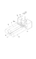
- FIG. 3 is a perspective view showing an arrangement relationship of the intermediate roll axle box 11, the reserve roll axle box 12, and the central reserve roll axle box 13 in the embodiment of the present invention.
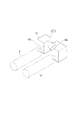
- FIG. 4 is a perspective view showing the reserved roll axle box 12 in the embodiment of the present invention.
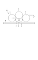
- FIG. 5 is a diagram showing an arrangement relationship of roll groups provided in the cluster structure 10 according to the embodiment of the present invention.
- the multi-stage cluster plate rolling mill 1 includes a work roll 2, a first intermediate roll 3 that squeezes the work roll 2 obliquely from the front in the rolling direction, and a second intermediate roll 4 that squeezes the rear obliquely.
- the first intermediate roll 3 is squeezed from the front diagonally
- the first secondary roll 5 is squeezed from the rear diagonally
- the first intermediate roll 3 and the second intermediate roll 4 are downwardly compressed.
- the cluster structure 10 including the central holding roll 7 is configured to face each other in the vertical direction (vertical direction).
- the workpiece (rolled material) W (see FIG. 2) is rolled between the opposing cluster structures 10.
- the same reference numerals are assigned to the same or equivalent components as the cluster structure 10, and the description is simplified. Or omitted.
- the first intermediate roll 3 and the second intermediate roll 4 are pivotally supported by a common intermediate roll axle box 11.
- the first backup roll 5 and the second backup roll 6 are pivotally supported by a common backup roll axle box 12.
- the central stand roll 7 is pivotally supported by a central stand roll axle box 13 provided independently of the reserve roll axle box 12. That is, the first intermediate roll 3 and the second intermediate roll 4 are positioned by the intermediate roll axle box 11 that supports them in common.
- the first stand roll 5 and the second stand roll 6 are positioned by a stand roll axle box 12 that pivotally supports them in common.
- the center stand roll 7 is positioned by the center stand roll axle box 13.
- the gavel roll 2a is supported by a shaft 2b, and the shaft 2b is supported by an arm (not shown) provided on the housing frame 17.
- a first recessed portion (concave portion) 12 a that forms a space at a position overlapping with the central reserved roll shaft box 13 in the vertical direction (opposite direction) is formed in the reserved roll shaft box 12.
- the stand roll roll box 12 and the center roll roll box 13 are combined so as to be relatively movable in the vertical direction.
- the reserve roll axle box 12 is formed with a second recess 12b that forms a space at a position overlapping the intermediate roll axle box 11 in the axial direction (horizontal direction).
- the intermediate roll axle box 11 and the reserve roll axle box 12 Are combined so as to be relatively movable in the axial direction.
- a roll bending device 14 is provided between the intermediate roll axle box 11 and the intermediate roll axle box 11 ′.
- the roll bending apparatus 14 includes a cylinder mechanism that can expand and contract in the vertical direction, and applies a bending load to the first intermediate rolls 3 and 3 ′ and the second intermediate rolls 4 and 4 ′.
- An intermediate roll shift device 15 that shifts the first intermediate roll 3 and the second intermediate roll 4 in the axial direction is connected to the intermediate roll axle box 11.
- the intermediate roll shift device 15 includes a first shift arm 15a connected to the intermediate roll axle box 11, and a second shift arm 15b on the shift device main body side.
- the second shift arm 15b sandwiches the first shift arm 15a with a roller that is rotatable around an axis extending in the direction perpendicular to the paper surface in FIG. 2, and the first shift arm 15a (intermediate roll axle box 11) is in the vertical direction. It is possible to move to.
- the second shift arm 15 b is supported on the housing frame 17 by the constituent members 21, 22, 23, and 24.
- the central holding roll axle box 13 is supported on the downward surface side of a beam (beam member) 16 extending in the horizontal direction. As shown in FIG. 1, the beam 16 is connected to a beam suspension cylinder 18 provided on the housing frame 17, and both ends thereof are guided by the housing frame 17. It is slidable in the vertical direction.
- the first reduction device 19 On the upward surface side of the beam 16, there is provided a first reduction device 19 that supports the beam 16 and slides the beam 16 in the vertical direction so as to reduce the central holding roll axle box 13.
- the first reduction device 19 of the present embodiment is an electric reduction device and is provided at the top of the housing frame 17.
- the first reduction device 19 drives the worm 19a and the worm wheel (not shown) to move the rod 19b in the vertical direction under the control of a control device (not shown).
- a load meter 25 for measuring the entire rolling force is provided.
- the first reduction device 19 ′ of the cluster structure 10 ′ is a hydraulic reduction device, and moves the rod in the vertical direction under the control of a control device (not shown).
- the holding roll axle box 12 is supported by the second reduction device 20 mounted on the beam 16 and is provided on the downward surface side of the beam 16.
- the second reduction device 20 of the present embodiment is a hydraulic reduction device, and includes a rod 26 of a hydraulic piston, a seal cover 27, and a hydraulic chamber 28.
- the second rolling-down device 20 moves the rod 26 in the vertical direction under the control of a control device (not shown), thereby rolling down the rolling-down roll box 12 independently of the central rolling-down roll box 13.
- the second reduction device 20 performs a reduction position control in combination with a sensor (not shown) that detects the stroke of the rod 26.
- the reserved roll axle box 12 and the central reserved roll axle box 13 are both mounted on the beam 16, but the reserved roll axle box 12 is supported by the beam 16 via the second reduction device 20.
- the central holding roll axle box 13 is rigidly supported by the beam 16. That is, the rolling position of the roll group included in the cluster structure 10 in the vertical direction, that is, the rolling force with respect to the workpiece W is determined by the slide stroke of the beam 16. Therefore, the gap set for setting the plate thickness of the workpiece W is determined by the positioning of the rod 19b in the first reduction device 19 or the pressure setting.
- the vertical position adjustment for adjusting the plate thickness of the workpiece W is performed only by the upper first reduction device 19.
- the lower first reduction device 19 ′ is used when the beam 16 ′ is moved up and down by roll recombination or the like, and is preset during rolling.
- the relative height Y (refer FIG. 5) of the 1st reservation roll 5, the 2nd reservation roll 6, and the center reservation roll 7 is set by setting the reduction stroke of the 2nd reduction apparatus 20.
- FIG. Variable setting Since the horizontal deflection of the first intermediate roll 3 and the second intermediate roll 4 can be controlled by changing the relative height Y, the vertical deflection of the work roll 2 is changed, and the shape of the workpiece W is made effective. Can be controlled. For example, when the load (stroke) by the second reduction device 20 is increased, the relative height Y is reduced, and the central reduction force on the workpiece W can be increased.
- the relative height Y is increased, and the central reduction force of the workpiece W can be reduced.
- the adjustment of the rolling force is controlled by a control device (not shown) so that the rolling force applied to the first and second rolls 5 and 6 and the rolling force applied to the central roll 7 have a predetermined ratio.
- a control device not shown
- the rolling force applied to the first and second rolls 5 and 6 and the rolling force applied to the central roll 7 have a predetermined ratio.
- the relative height Y between the first and second backup rolls 5 and 6 and the central backup roll 7 has a desirable reference position determined from the control range.
- the stroke position of the rod 26 of the second reduction device 20 is preset so as to be the reference position. Note that the lower second reduction device 20 'is similarly controlled.
- the stroke position of the rod 19 b of the first reduction device 19 is determined.
- the stroke position is a value that reflects the elastic deformation of the machine based on the expected rolling load.
- the thickness of the rolled workpiece W is measured with a thickness meter.
- the thickness deviation is obtained from the measurement result. If the deviation is large, an AGC (Auto Gauge Control) operation is performed.
- the stroke position of the first reduction device 19 is corrected.
- the control mode is switched to the rolling load control (rolling pressure control) instead of the roll gap control after the start of rolling, the pressure setting of the first reduction device 19 is corrected.
- the tension AGC and the speed AGC are being performed, the setting of the first reduction device 19 is not changed.
- the stroke position of the second reduction device 20, 20 ' is corrected. Even when the control mode is switched not to roll gap control but to rolling load control after the start of rolling, feedback control is performed to correct the stroke positions of the second reduction devices 20 and 20 '. Incidentally, the control amounts for the second reduction devices 20, 20 ′ are in principle the same amount. Further, when the above-described reduction force ratio control is performed, the reduction force ratio is changed according to the shape defect of the workpiece W, and the pressure of the second reduction device 20 is changed. The relation between the degree of the shape defect of the workpiece W and the stroke of the relative height Y, or the relationship between the degree of the shape defect of the workpiece W and the ratio of the above-mentioned rolling force is determined in advance by theoretical calculation or operation.
- the compensation correction coefficient uses data in which arithmetic logic is stored in advance in a control device (not shown). In this embodiment, the reduction control is performed in this way.
- the multi-stage cluster plate rolling mill 1 includes a work roll 2, a first intermediate roll 3 and a second intermediate roll 4 provided behind the work roll 2, and the first intermediate roll.
- the first holding roll 5 provided behind the roll 3
- the second holding roll 6 provided behind the second intermediate roll 4
- the cluster structure 10 provided with the central center roll 7 formed is configured to face each other.
- the cluster structure 10 is provided independently of the reserved roll shaft box 12 while supporting the reserved roll shaft box 12 for supporting the first reserved roll 5 and the second reserved roll 6 in common and the central reserved roll 7.
- the central storage roll shaft box 13 and the central storage roll shaft box 13 are supported, the beam 16 is slidable in the opposing direction integrally with the central storage roll shaft box 13, and the beam 16 is supported.
- the first rolling-down device 19 that slides 16 down the center holding roll shaft box 13 in the vertical direction, and is mounted on the beam 16 to support the holding roll shaft box 12 and independent of the central holding roll shaft box 13.
- a second rolling-down device 20 that slides down the roll roll box 12 in the vertical direction.
- the multi-stage cluster plate rolling mill 1 according to the present embodiment adopts a configuration in which a first rolling reduction device dedicated to a central backup roll is built in a backup roll axle box that pivotally supports the first and second backup rolls as in the prior art.
- the first reduction device 19 is installed on the beam 16 that is slidable in the vertical direction together with the central holding roll axle box 13.
- the central backup roll 7 is crushed through the beam 16 without being supported in the form of the support roll axle box 12 that pivotally supports the first backup roll 5 and the second backup roll 6 via the support load.
- first backup roll 5 and the second backup roll 6 are not directly subjected to the fluctuation of the rolling force fluctuation of the central storage axle box, the fluctuation of the backup roll due to the disturbance is not increased, and the fluctuation due to the disturbance is reduced. it can. Furthermore, since the first reduction device 19 is not built in the standby roll axle box 12, the burden of the removal work is reduced.
- the first reduction device 19 and the second reduction device 19 are configured so that the reduction force applied to the central backup roll 7 and the reduction force applied to the first reservation roll 5 and the second reservation roll 6 become a predetermined ratio.
- a control device that controls driving of the reduction device 20 is included.
- the control device applies a rolling force to the first and second rolls 6 and 6 independently of the central roll 7 and the rolling force applied to the first and second rolls 5 and 6. Is controlled so as to have a predetermined ratio to the rolling force applied to the central holding roll 7.
- the multistage cluster plate rolling mill 1 can apply an appropriate reduction force to the three standby rolls.
- the reduction stroke of the second reduction device 20 can be determined based on the relationship between the rolling shape defect of the workpiece W and the relative height Y.
- the reserve roll axle box 12 is formed with a first recess 12a that forms a space at a position overlapping the central reserve roll axle box 13 in the vertical direction.
- the intermediate roll shaft box 11 that pivotally supports the first intermediate roll 3 and the second intermediate roll 4, and the first intermediate roll 3 and the second intermediate roll 11 connected to the intermediate roll axle box 11.
- an intermediate roll shift device 15 that shifts the intermediate roll 4 in the axial direction.
- the retentive roll axle box 12 is formed with a second recess 12b that forms a space at a position overlapping the intermediate roll axle box 11 in the axial direction.
- the first reduction device 19 of the cluster structure 10 is an electric reduction device, and the first reduction device 19 ′ of the cluster structure 10 ′ is a hydraulic reduction device. It is not preferable to adjust the rolling force when the first rolling devices 19, 19 'of the cluster structures 10, 10' facing each other have the same configuration. For this reason, the first reduction device 19 included in one cluster structure 10 is electrically operated, and the first reduction device 19 ′ included in the other cluster structure 10 ′ is hydraulic, so that the reduction force can be easily adjusted. .
- the strength and output load of the central backup roll can be increased, and the individual load on the central backup roll can be increased.
- the first and second backup rolls are not directly subjected to the fluctuation of the rolling force fluctuation of the central backup axle box, the fluctuation of the backup roll due to the disturbance is not increased, and the fluctuation due to the disturbance can be reduced. Furthermore, since the first reduction device is not built in the stay roll axle box, the removal work is not time-consuming.
Landscapes
- Engineering & Computer Science (AREA)
- Mechanical Engineering (AREA)
- Metal Rolling (AREA)
- Paper (AREA)
Abstract
Priority Applications (1)
| Application Number | Priority Date | Filing Date | Title |
|---|---|---|---|
| CN201180010748.4A CN102791392B (zh) | 2010-02-26 | 2011-02-22 | 多级辊组板轧机 |
Applications Claiming Priority (2)
| Application Number | Priority Date | Filing Date | Title |
|---|---|---|---|
| JP2010042433A JP5428939B2 (ja) | 2010-02-26 | 2010-02-26 | 多段クラスタ板圧延機 |
| JP2010-042433 | 2010-02-26 |
Publications (1)
| Publication Number | Publication Date |
|---|---|
| WO2011105354A1 true WO2011105354A1 (fr) | 2011-09-01 |
Family
ID=44506761
Family Applications (1)
| Application Number | Title | Priority Date | Filing Date |
|---|---|---|---|
| PCT/JP2011/053795 Ceased WO2011105354A1 (fr) | 2010-02-26 | 2011-02-22 | Laminoir à tôles en grappes à étages multiples |
Country Status (3)
| Country | Link |
|---|---|
| JP (1) | JP5428939B2 (fr) |
| CN (1) | CN102791392B (fr) |
| WO (1) | WO2011105354A1 (fr) |
Citations (4)
| Publication number | Priority date | Publication date | Assignee | Title |
|---|---|---|---|---|
| JPS606205A (ja) * | 1983-06-23 | 1985-01-12 | Mitsubishi Heavy Ind Ltd | 多段クラスタ圧延機 |
| JP2000210705A (ja) * | 1999-01-27 | 2000-08-02 | Ishikawajima Harima Heavy Ind Co Ltd | 多段圧延機 |
| JP2004098073A (ja) * | 2002-09-05 | 2004-04-02 | Ishikawajima Harima Heavy Ind Co Ltd | 多段圧延機 |
| JP2005059087A (ja) * | 2003-08-20 | 2005-03-10 | Ishikawajima Harima Heavy Ind Co Ltd | クラスタ圧延機 |
Family Cites Families (3)
| Publication number | Priority date | Publication date | Assignee | Title |
|---|---|---|---|---|
| AP2091A (en) * | 1999-03-04 | 2010-01-18 | Zheng Hongzhuan | A rolling mill with roll deflection bi-dimensionally controlled. |
| CN100579681C (zh) * | 2008-01-25 | 2010-01-13 | 中冶陕压重工设备有限公司 | 用于十二辊可控辊形轧机的辊形调整机构 |
| CN101342543B (zh) * | 2008-08-18 | 2010-06-16 | 中冶陕压重工设备有限公司 | 十四辊带钢轧机 |
-
2010
- 2010-02-26 JP JP2010042433A patent/JP5428939B2/ja not_active Expired - Fee Related
-
2011
- 2011-02-22 CN CN201180010748.4A patent/CN102791392B/zh not_active Expired - Fee Related
- 2011-02-22 WO PCT/JP2011/053795 patent/WO2011105354A1/fr not_active Ceased
Patent Citations (4)
| Publication number | Priority date | Publication date | Assignee | Title |
|---|---|---|---|---|
| JPS606205A (ja) * | 1983-06-23 | 1985-01-12 | Mitsubishi Heavy Ind Ltd | 多段クラスタ圧延機 |
| JP2000210705A (ja) * | 1999-01-27 | 2000-08-02 | Ishikawajima Harima Heavy Ind Co Ltd | 多段圧延機 |
| JP2004098073A (ja) * | 2002-09-05 | 2004-04-02 | Ishikawajima Harima Heavy Ind Co Ltd | 多段圧延機 |
| JP2005059087A (ja) * | 2003-08-20 | 2005-03-10 | Ishikawajima Harima Heavy Ind Co Ltd | クラスタ圧延機 |
Also Published As
| Publication number | Publication date |
|---|---|
| JP5428939B2 (ja) | 2014-02-26 |
| CN102791392A (zh) | 2012-11-21 |
| CN102791392B (zh) | 2014-11-26 |
| JP2011177729A (ja) | 2011-09-15 |
Similar Documents
| Publication | Publication Date | Title |
|---|---|---|
| JP5328876B2 (ja) | ロールプレス設備 | |
| JP3747786B2 (ja) | 板材用圧延機の圧延方法及び板材用圧延設備 | |
| CA2681886C (fr) | Dispositif de laminage, en particulier cage a cylindres a mouvement transversal | |
| JP7027155B2 (ja) | フレーム成形装置 | |
| JP5742703B2 (ja) | 金属板材の圧延機および圧延方法 | |
| CN102303049B (zh) | 轧机轴承座的定位装置 | |
| JP5059250B1 (ja) | 金属板材の圧延機および圧延方法 | |
| CN101633000A (zh) | 一种中间辊轴向移动装置 | |
| CN102371291A (zh) | 一种多梁板材矫平机 | |
| JP5097863B1 (ja) | ロールプレス設備 | |
| CN102821881B (zh) | 金属板材的轧机及轧制方法 | |
| JP5428939B2 (ja) | 多段クラスタ板圧延機 | |
| CN1571709A (zh) | 轧制装置 | |
| WO2019187508A1 (fr) | Laminoir et procédé de commande d'un laminoir | |
| JPH07284821A (ja) | 多数本のロールの支持構造物 | |
| CN102481609A (zh) | 用于调节轧机机架的轧辊的方法和轧机机架 | |
| JP5712620B2 (ja) | 金属板材の圧延機 | |
| JP2003522643A (ja) | ロールの撓みが2次元的に制御される圧延機 | |
| RU2010108239A (ru) | Прокатное устройтво с механизмом регулирования | |
| JPS6232001B2 (fr) | ||
| JP2012157876A (ja) | 金属板材の厚板圧延機 | |
| JP4969220B2 (ja) | 圧延機 | |
| JP2019171409A (ja) | ベンディングロール機 | |
| JP2993187B2 (ja) | クロスミル | |
| RU2405642C1 (ru) | Прокатная клеть |
Legal Events
| Date | Code | Title | Description |
|---|---|---|---|
| WWE | Wipo information: entry into national phase |
Ref document number: 201180010748.4 Country of ref document: CN |
|
| 121 | Ep: the epo has been informed by wipo that ep was designated in this application |
Ref document number: 11747315 Country of ref document: EP Kind code of ref document: A1 |
|
| NENP | Non-entry into the national phase |
Ref country code: DE |
|
| WWE | Wipo information: entry into national phase |
Ref document number: 7752/DELNP/2012 Country of ref document: IN |
|
| 122 | Ep: pct application non-entry in european phase |
Ref document number: 11747315 Country of ref document: EP Kind code of ref document: A1 |