WO2011108128A1 - Douille d'ampoule d'éclairage - Google Patents
Douille d'ampoule d'éclairage Download PDFInfo
- Publication number
- WO2011108128A1 WO2011108128A1 PCT/JP2010/060047 JP2010060047W WO2011108128A1 WO 2011108128 A1 WO2011108128 A1 WO 2011108128A1 JP 2010060047 W JP2010060047 W JP 2010060047W WO 2011108128 A1 WO2011108128 A1 WO 2011108128A1
- Authority
- WO
- WIPO (PCT)
- Prior art keywords
- holding member
- base
- socket
- case
- terminal portions
- Prior art date
- Legal status (The legal status is an assumption and is not a legal conclusion. Google has not performed a legal analysis and makes no representation as to the accuracy of the status listed.)
- Ceased
Links
Images



Classifications
-
- H—ELECTRICITY
- H01—ELECTRIC ELEMENTS
- H01R—ELECTRICALLY-CONDUCTIVE CONNECTIONS; STRUCTURAL ASSOCIATIONS OF A PLURALITY OF MUTUALLY-INSULATED ELECTRICAL CONNECTING ELEMENTS; COUPLING DEVICES; CURRENT COLLECTORS
- H01R33/00—Coupling devices specially adapted for supporting apparatus and having one part acting as a holder providing support and electrical connection via a counterpart which is structurally associated with the apparatus, e.g. lamp holders; Separate parts thereof
- H01R33/94—Holders formed as intermediate parts for linking a counter-part to a coupling part
-
- F—MECHANICAL ENGINEERING; LIGHTING; HEATING; WEAPONS; BLASTING
- F21—LIGHTING
- F21V—FUNCTIONAL FEATURES OR DETAILS OF LIGHTING DEVICES OR SYSTEMS THEREOF; STRUCTURAL COMBINATIONS OF LIGHTING DEVICES WITH OTHER ARTICLES, NOT OTHERWISE PROVIDED FOR
- F21V14/00—Controlling the distribution of the light emitted by adjustment of elements
- F21V14/02—Controlling the distribution of the light emitted by adjustment of elements by movement of light sources
-
- F—MECHANICAL ENGINEERING; LIGHTING; HEATING; WEAPONS; BLASTING
- F21—LIGHTING
- F21V—FUNCTIONAL FEATURES OR DETAILS OF LIGHTING DEVICES OR SYSTEMS THEREOF; STRUCTURAL COMBINATIONS OF LIGHTING DEVICES WITH OTHER ARTICLES, NOT OTHERWISE PROVIDED FOR
- F21V19/00—Fastening of light sources or lamp holders
- F21V19/006—Fastening of light sources or lamp holders of point-like light sources, e.g. incandescent or halogen lamps, with screw-threaded or bayonet base
-
- F—MECHANICAL ENGINEERING; LIGHTING; HEATING; WEAPONS; BLASTING
- F21—LIGHTING
- F21V—FUNCTIONAL FEATURES OR DETAILS OF LIGHTING DEVICES OR SYSTEMS THEREOF; STRUCTURAL COMBINATIONS OF LIGHTING DEVICES WITH OTHER ARTICLES, NOT OTHERWISE PROVIDED FOR
- F21V19/00—Fastening of light sources or lamp holders
- F21V19/02—Fastening of light sources or lamp holders with provision for adjustment, e.g. for focusing
-
- H—ELECTRICITY
- H01—ELECTRIC ELEMENTS
- H01R—ELECTRICALLY-CONDUCTIVE CONNECTIONS; STRUCTURAL ASSOCIATIONS OF A PLURALITY OF MUTUALLY-INSULATED ELECTRICAL CONNECTING ELEMENTS; COUPLING DEVICES; CURRENT COLLECTORS
- H01R33/00—Coupling devices specially adapted for supporting apparatus and having one part acting as a holder providing support and electrical connection via a counterpart which is structurally associated with the apparatus, e.g. lamp holders; Separate parts thereof
- H01R33/05—Two-pole devices
- H01R33/22—Two-pole devices for screw type base, e.g. for lamp
-
- H—ELECTRICITY
- H01—ELECTRIC ELEMENTS
- H01R—ELECTRICALLY-CONDUCTIVE CONNECTIONS; STRUCTURAL ASSOCIATIONS OF A PLURALITY OF MUTUALLY-INSULATED ELECTRICAL CONNECTING ELEMENTS; COUPLING DEVICES; CURRENT COLLECTORS
- H01R35/00—Flexible or turnable line connectors, i.e. the rotation angle being limited
- H01R35/04—Turnable line connectors with limited rotation angle with frictional contact members
-
- F—MECHANICAL ENGINEERING; LIGHTING; HEATING; WEAPONS; BLASTING
- F21—LIGHTING
- F21K—NON-ELECTRIC LIGHT SOURCES USING LUMINESCENCE; LIGHT SOURCES USING ELECTROCHEMILUMINESCENCE; LIGHT SOURCES USING CHARGES OF COMBUSTIBLE MATERIAL; LIGHT SOURCES USING SEMICONDUCTOR DEVICES AS LIGHT-GENERATING ELEMENTS; LIGHT SOURCES NOT OTHERWISE PROVIDED FOR
- F21K9/00—Light sources using semiconductor devices as light-generating elements, e.g. using light-emitting diodes [LED] or lasers
- F21K9/20—Light sources comprising attachment means
- F21K9/23—Retrofit light sources for lighting devices with a single fitting for each light source, e.g. for substitution of incandescent lamps with bayonet or threaded fittings
- F21K9/232—Retrofit light sources for lighting devices with a single fitting for each light source, e.g. for substitution of incandescent lamps with bayonet or threaded fittings specially adapted for generating an essentially omnidirectional light distribution, e.g. with a glass bulb
-
- F—MECHANICAL ENGINEERING; LIGHTING; HEATING; WEAPONS; BLASTING
- F21—LIGHTING
- F21S—NON-PORTABLE LIGHTING DEVICES; SYSTEMS THEREOF; VEHICLE LIGHTING DEVICES SPECIALLY ADAPTED FOR VEHICLE EXTERIORS
- F21S8/00—Lighting devices intended for fixed installation
- F21S8/02—Lighting devices intended for fixed installation of recess-mounted type, e.g. downlighters
- F21S8/026—Lighting devices intended for fixed installation of recess-mounted type, e.g. downlighters intended to be recessed in a ceiling or like overhead structure, e.g. suspended ceiling
-
- F—MECHANICAL ENGINEERING; LIGHTING; HEATING; WEAPONS; BLASTING
- F21—LIGHTING
- F21Y—INDEXING SCHEME ASSOCIATED WITH SUBCLASSES F21K, F21L, F21S and F21V, RELATING TO THE FORM OR THE KIND OF THE LIGHT SOURCES OR OF THE COLOUR OF THE LIGHT EMITTED
- F21Y2115/00—Light-generating elements of semiconductor light sources
- F21Y2115/10—Light-emitting diodes [LED]
Definitions
- the present invention relates to a light bulb socket for electrically connecting, for example, a general lighting socket and a light bulb type lamp.
- a light bulb type lamp such as an incandescent light bulb, a light bulb type fluorescent lamp or an LED light bulb is known.
- this type of bulb-type lamp for example, there is an LED bulb that is mounted on a ceiling-embedded lighting fixture (see, for example, Patent Document 1).
- This conventional LED bulb has a structure in which a screw-type base is mounted on one side of a cover and a spherical lamp is rotatably supported on the other side of the cover.
- An LED light emitting diode
- a lighting device is disposed inside the base. The lighting device is electrically connected to the light emitting diode via a lead wire.
- This conventional LED bulb is capable of freely rotating and swinging the lamp relative to the cover, and the direction of light irradiation from the light emitting diode can be freely changed according to the rotation and swing of the lamp. To do. Thereby, the illumination light from a lamp can be adjusted to a desired direction.
- the conventional LED bulb described in Patent Document 1 uses a lead wire for wiring between the light emitting diode and the lighting device. For this reason, the movable range of the lamp body is restricted by the length of the lead wire, and there is a problem that an area where the irradiation light from the lamp body cannot reach or an area where irradiation is impossible occurs.
- the rotation swing angle of the lamp changes every time the light irradiation direction of the light emitting diode is changed, so that the lead wire is bent or twisted. For this reason, there has been a problem that the lead wire may break due to long-term use.
- an object of the present invention is to provide a socket for a light bulb that has improved durability and reliability of mechanical connection and electrical connection between a general lighting socket and a light bulb type lamp.
- the present invention provides a cylindrical first holding member having a base on one side and an opening on the other side, and is movable within the opening of the first holding member.
- a cylindrical second holding member that is supported, and a cylindrical third holding member that is provided with a socket holder for holding the lamp and is rotatably supported by the second holding member.
- a light bulb socket is provided.
- the second holding member is supported in a linearly movable and rotationally movable manner in an opening of the first holding member.
- one end of the first holding member is provided to be rotatable around an axis of the base, and the other end extends in the axial direction.
- First and second cap terminal portions are provided, and the second holding member is provided on the first and second cap terminal portions so as to be slidable along the axial direction.
- the third holding member has one end provided on the socket receiver and the other end rotatably provided on the first and second connection terminal portions.
- the second holding member includes a pair of arms that rotatably support the third holding member. It is characterized by that.
- the second holding member and the arm have an inner / outer double wall structure having an inner wall and an outer wall, and a space formed between the inner wall and the outer wall.
- a part of the first and second connecting terminal portions is housed, and the third holding member has a support shaft extending into the space through the arm, and the third holding member has the support shaft extending through the support shaft.
- the first and second receiving terminal portions and the first and second connecting terminal portions are electrically connected to each other.
- the present invention secures mechanical connection and electrical connection between the first to third holding members constituting the socket for a light bulb, and allows the second and third holding members to freely move between each other. It becomes possible, and the light irradiation direction can be freely adjusted according to the arrangement state of the existing lighting fixtures.
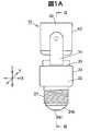
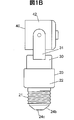
- FIG. 3 is an enlarged sectional view taken along line III-III in FIG. 1A. It is a principal part expansion perspective view for demonstrating one component of the socket for light bulbs.
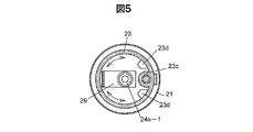
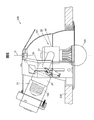
- FIG. 5 is an enlarged cross-sectional view of a main part cut out along the line VV in FIG. 3. It is a partial cross section side view for demonstrating the illuminating device which is 2nd Embodiment using the socket for light bulbs.
- reference numeral 10 generally indicates a configuration example of a light bulb socket.
- the socket 10 for a light bulb includes a base side case 20 that is a first holding member having a base 21, a connection terminal case 30 that is a second holding member, and a receiving side that is a third holding member having a socket base 41. It is mainly composed of three structural members that are mechanically and electrically connected to the case 40.
- the base-side case 20, the connection terminal case 30, and the receiving-side case 40 are made of, for example, polyamide resin and are formed in a cylindrical shape.
- the base 21 of the base side case 20 is made of, for example, a synthetic resin or metal having heat resistance or electrical insulation, and is formed in a bottomed cylindrical shape.
- the bulb socket 10 maintains a freely three-dimensional posture by linear movement in the Z-axis direction and rotational movement around the XYZ axes. It has a first main configuration that makes it possible.
- the base side case 20, the connection terminal case 30, and the receiving side case 40 are arranged on the same axis (Z axis).
- the connection terminal case 30 and the receiving side case 40 can be moved along the axial direction (Z-axis direction) of the base-side case 20 and can be rotated around the axial line (around the Z-axis) of the base-side case 20. It is said that.
- the receiving side case 40 is rotatable with respect to the connecting terminal case 30 around an axis (XY axis) perpendicular to the axis (Z axis).
- the base-side case 20 has a staircase shape including a large-diameter cylindrical case 22 and a small-diameter cylindrical case 23 that is fitted and fixed to the inner peripheral surface of the large-diameter cylindrical case 22. is doing.
- an annular locking piece 22a is provided projecting radially inward.
- An annular flange 23a formed at the opening edge of the small-diameter cylindrical case 23 on the large-diameter cylindrical case 22 side is fixed to the inner peripheral surface of the locking piece 22a.
- a cylindrical mounting boss 23b protrudes from the opening edge of the small-diameter cylindrical case 23 opposite to the flange 23a.
- a base 21 surrounding the small diameter cylindrical case 23 is fitted on the outer peripheral surface of the locking piece 22a of the large diameter cylindrical case 22.
- the base 21 is fastened and fixed to the both ends in the longitudinal direction of the mounting boss 23b with screws 24c via an annular celestial fixing bracket 24a and a cylindrical pedestal 24b.
- 24b is supported by the base case 20.
- a material of the pedestal 24b for example, a polyamide resin is used.
- standards such as E26 type and E17 type used for general lighting bulbs can be used.
- connection terminal case 30 has an inner / outer double wall structure including an inner wall 30a and an outer wall 30b.
- a pair of arms 31, 31 on both ends extend in the Z-axis direction on the outer periphery on the distal end side of the connection terminal case 30, and the receiving side case 40 is rotatably supported between the arms 31.
- a space 32 formed in the inner and outer double walls of the connection terminal case 30 is a storage space for accommodating a conductive member forming a part of a power distribution path between the base 21 and the socket receiver 41.
- An annular groove 30 c is formed on the outer periphery on the proximal end side of the connection terminal case 30.
- An annular contact ring 36 made of silicon rubber is fitted into the annular groove 30c.
- connection terminal case 30 is elastically and liquid-tightly contacted with the inner peripheral surface of the base-side case 20 via a contact ring 36 as shown in FIGS. 2A to 3.
- the connection terminal case 30 is supported by the contact ring 36 so as to be rotatable in the circumferential direction of the base side case 20 and is supported so as to be movable in the Z-axis direction of the base side case 20.
- the connection terminal case 30 so as to be expandable and contractible in the Z-axis direction with respect to the base-side case 20, and to arrange the connection terminal case 30 so as to be rotatable around the Z-axis.
- the receiving side case 40 can be arranged so as to be rotatable around the X axis and the Y axis.
- the money receiving side case 40 has a main body case 42 having an open end.
- a cap-shaped cover plate 43 is attached to the surface of the main body case 42 opposite to the opening side with screws.
- On the outer peripheral surface of the main body case 42 a pair of both support shafts 44, 44 project from the same plane.
- the support shaft 44 is rotatably supported by the conductive fittings 33 a and 33 b of the connection terminal case 30 through a through hole 31 a formed through the tip of the arm 31 of the connection terminal case 30.
- the bulb socket 10 further includes three components, that is, a base side case 20, a connection terminal case 30, and a power receiving side case 40, as a power distribution path between the base 21 and the socket power receiving 41.
- the second main configuration is provided with an electrical connection structure that is electrically connected to each other without wiring (wireless).
- this electrical connection structure is a structure that maintains the electrical connection state between the linear movement range in the Z-axis direction and the rotational movement range around the XYZ axes of the connection terminal case 30 and the receiving-side case 40. It has become.
- a cylindrical rib 23c is formed on the inner peripheral surface of the small-diameter cylindrical case 23 of the base-side case 20, as shown in FIG.
- a first connection fitting 25 extending radially inward is disposed on the inner end surface of the cylindrical rib 23c.
- the connection fitting 25 and the base connection piece 26 are screwed to the inner and outer end surfaces of the cylindrical rib 23c and are electrically connected to each other.
- a first conductive fitting 27 is rotatably supported at the tip of the connection fitting 25 via a support shaft 28, and can be rotated together with the connection terminal case 30.
- the first conductive metal fitting 27 is formed in a stepped manner in the Z-axis direction of the large diameter cylindrical case 22 and is electrically connected to the first connection metal fitting 25.
- a first base terminal portion is formed by the connection fitting 25, the base connection piece 26, and the conductive fitting 27.
- the second connection fitting 29 bent in an L shape toward the Z-axis direction of the large-diameter cylindrical case 22 is arranged with a phase difference of 180 degrees from the first conductive fitting 27.
- the base end portion of the second connection fitting 29 is rotatably supported via a support shaft 24a-1 formed on a base fixing bracket 24a for fixing the base, and the support shaft 24a-1 is the center of rotation. And can be rotated together with the connection terminal case 30.
- the second connection fitting 29 and the screw 24c for fixing the cap serving as a screw terminal are electrically connected via the top fixing bracket 24a.
- a second base terminal portion is constituted by the second connection fitting 29, the top fixing bracket 24 a and the screw 24 c.
- the distal end portion of the first conductive metal fitting 27 and the distal end portion of the second connection metal fitting 29 are elongated slit-shaped for guiding the connection terminal case 30 in the Z-axis direction.
- Guide holes 27a and 29a are formed.
- the guide hole 27 a of the first conductive fitting 27 is set longer than the length dimension of the guide hole 29 a of the second connection fitting 29.
- a pair of protruding step portions 23d and 23d are formed on the inner peripheral surface of the large-diameter cylindrical case 22 of the base side case 20 with the cylindrical rib 23c interposed therebetween.
- the projecting step portions 23 d and 23 d abut on the second connection fitting 29 that rotates together with the connection terminal case 30 when the connection terminal case 30 rotates, thereby restricting the rotation range of the connection terminal case 30. It has become.
- connection terminal case 30 accommodates a conductive metal fitting 33 a as a first connection terminal portion and a 33 b as a second connection terminal portion, respectively.
- the conductive metal fittings 33a and 33b are bent in a stepped manner toward the Z-axis direction of the connection terminal case 30 and have the same structure.
- the base end portion of the first conductive metal fitting 33 a is electrically connected to the conductive metal fitting 27 of the base side case 20 via a caulking rivet 34.
- the base end portion of the second conductive metal fitting 33 b is electrically connected to the connection metal fitting 29 of the base-side case 20 via a caulking rivet 34.
- a plurality of protrusions 30d,..., 30d protrude from the inner surface of the inner wall 30a of the arm 31.
- the plurality of protrusions 30d are for sandwiching the tip ends of the conductive metal fittings 33a and 33b between the inner wall 30a and the outer wall 30b of the arm 31.
- the conductive metal members 33a and 33b are positioned and fixed in the space 32 of the arm 31 by a plurality of protrusions 30d.
- a bottomed cylindrical socket receiver 41 that can be screwed into a light bulb type lamp is disposed inside the receiver-side case 40.
- a receiving-side conductive metal fitting 46 that is a first receiving terminal portion and a contact piece 45 that is a second receiving terminal portion are arranged in the radial direction of the receiving-side case 40. Relative to each other.
- the contact piece 45 is partitioned so as not to come into contact with the bottom of the socket receiver 41 as shown in FIGS. 2A to 3.
- the contact piece 45 and the metal receiving side conductive metal fitting 46 are fixed to the bottom of the socket metal receiving plate 41 with screws.
- standards such as E26 type and E17 type used in general light bulb type lamps can be used.
- the socket receiver 41 is electrically connected by being in contact with the cap of the light bulb type lamp.
- the base end portion of the contact piece 45 penetrates between the main body case 42 and the cover plate 43 of the money receiving side case 40 and is one pivot 44 of the money receiving side case 40. And is electrically connected to the second conductive fitting 33b of the connection terminal case 30.
- the base end portion of the metal receiving side metal fitting 46 penetrates between the body case 42 and the cover plate 43 of the metal receiving side case 40 and is fitted into the other support shaft 44 of the metal receiving side case 40,
- the case 30 is electrically connected to the first conductive fitting 33a.
- the first circuit is formed by the top fixing bracket 24a, the screw 24c, the second connection bracket 29, the second conductive bracket 33b, and the contact piece 45.
- the second connection circuit 25 is formed by the first connection fitting 25, the base connection piece 26, the first conductive fitting 27, the first conductive fitting 33a, and the receiving-side conductive fitting 46.
- the circuit structure formed between the base 21 and the socket receiver 41 is formed inside the structure including the base side case 20, the connection terminal case 30, and the receiver side case 40. Electrical connection is maintained in the linear movement range and the rotational movement range.
- the following various effects can be obtained.
- (2) The connection terminal case 30 and the receiving side case 40 can be freely moved along the Z axis direction of the base side case 20 and are connected at desired positions in the Z axis direction of the base side case 20.
- the terminal case 30 and the receiving side case 40 can be freely moved in two planes orthogonal to each other.
- (4) The use of the lead wire for electrically coupling the light bulb type lamp and the lighting fixture can be abolished to eliminate the disconnection of the lead wire, and the quality of the socket 10 for the light bulb can be improved.
- the light bulb socket 10 configured as described above can be effectively applied to, for example, a ceiling-embedded lighting fixture.
- FIG. 6 schematically shows an example of a ceiling-embedded lighting fixture 100 equipped with the light bulb socket 10 according to the first embodiment.
- the substantially same members as those in the first embodiment are given the same member names and symbols. Therefore, a detailed description of substantially the same members as those in the first embodiment is omitted.
- reference numeral 100 indicating the whole indicates a lighting fixture (downlight) embedded in the ceiling 200.
- a commercial AC power input socket 102 for general lighting to which the light bulb socket 10 is attached is fixed to the cover body 101.
- An LED bulb 103 is attached to the bulb socket 10.
- the center of the LED bulb 103 is arranged to coincide with the center of the opening of the instrument body 101. In the example of illustration, it arrange
- FIG. By screwing the light bulb socket 10 into the commercial AC power input socket 102 and inserting it, the commercial AC power is supplied to the LED light bulb 103 via the electrical connection structure of the light bulb socket 10 to light the LED light bulb 103.
- the LED bulb 103 When the top portion of the LED bulb 103 is directed to the opening of the appliance main body 101, the illumination light from the LED bulb 103 is directly emitted downward from the opening of the appliance main body 101. Since the light irradiation direction of the LED bulb 103 changes according to the movement of the bulb socket 10 in the Z-axis direction and the rotational movement about the XYZ axes, the LED bulb 103 can be illuminated with a freely held posture. Since the center of the LED bulb 103 can be placed on the center line O of the fixture body 101 by moving the bulb socket 10, the bulb socket 10 can be effectively attached to a bulb-type lamp such as an incandescent bulb or a bulb-type fluorescent lamp. The light bulb socket 10 can be used effectively regardless of the size of the instrument body 101.
- the downlight used by being embedded in the ceiling or wall of the building has been described.
- the present invention is not limited to this.
- the present invention can be effectively applied to various types of lighting fixtures such as downlights for facilities and business use, and spotlights for direct ceiling mounting.
Landscapes
- Engineering & Computer Science (AREA)
- General Engineering & Computer Science (AREA)
- Non-Portable Lighting Devices Or Systems Thereof (AREA)
- Arrangement Of Elements, Cooling, Sealing, Or The Like Of Lighting Devices (AREA)
- Connecting Device With Holders (AREA)
Abstract
La présente invention a trait à une douille d'ampoule d'éclairage dont la durabilité et la fiabilité des connexions mécaniques et électriques entre une douille d'éclairage à usage général et une lampe de type à ampoule d'éclairage sont améliorées. La douille d'ampoule d'éclairage (10) comprend : un premier élément de support cylindrique (20) qui est pourvu d'une base (21) sur un de ses côtés et d'une ouverture sur l'autre côté ; un deuxième élément de support cylindrique (30) qui est supporté de façon linéaire et mobile ainsi que de façon rotative et mobile à l'intérieur de l'ouverture du premier élément de support (20) ; et un troisième élément de support cylindrique (40) qui est supporté de façon rotative par le deuxième élément de support (30). Une douille de lampe (41) permettant de supporter une lampe est formée à l'intérieur de l'ouverture du troisième élément de support (40).
Applications Claiming Priority (2)
| Application Number | Priority Date | Filing Date | Title |
|---|---|---|---|
| JP2010045267A JP5510925B2 (ja) | 2010-03-02 | 2010-03-02 | 電球用ソケット |
| JP2010-045267 | 2010-03-02 |
Publications (1)
| Publication Number | Publication Date |
|---|---|
| WO2011108128A1 true WO2011108128A1 (fr) | 2011-09-09 |
Family
ID=44541805
Family Applications (1)
| Application Number | Title | Priority Date | Filing Date |
|---|---|---|---|
| PCT/JP2010/060047 Ceased WO2011108128A1 (fr) | 2010-03-02 | 2010-06-14 | Douille d'ampoule d'éclairage |
Country Status (2)
| Country | Link |
|---|---|
| JP (1) | JP5510925B2 (fr) |
| WO (1) | WO2011108128A1 (fr) |
Cited By (5)
| Publication number | Priority date | Publication date | Assignee | Title |
|---|---|---|---|---|
| JP2013145650A (ja) * | 2012-01-13 | 2013-07-25 | Iris Ohyama Inc | Ledランプ |
| WO2015049212A1 (fr) * | 2013-10-01 | 2015-04-09 | Mike Kausler | Module de support d'un moyen d'éclairage |
| WO2016139526A1 (fr) * | 2015-03-04 | 2016-09-09 | Luxdb S.R.L. | Combinaison d'un adaptateur de support de lampe et d'un contenant pour au moins un transducteur |
| FR3038149A1 (fr) * | 2015-06-23 | 2016-12-30 | Eur'ohm | Ensemble d'une fiche et d'une douille |
| ITUB20152006A1 (it) * | 2015-07-08 | 2017-01-08 | Andrea Cincotto | Combinazione di un adattatore portalampada e di un contenitore per almeno un trasduttore, ad esempio un trasduttore elettroacustico |
Families Citing this family (3)
| Publication number | Priority date | Publication date | Assignee | Title |
|---|---|---|---|---|
| JP5906949B2 (ja) * | 2012-06-04 | 2016-04-20 | 株式会社ムサシ | 電球用アダプタ |
| JP2015015219A (ja) * | 2013-07-08 | 2015-01-22 | 株式会社エス・ケー・ジー | 電球用ソケット |
| JP6384757B2 (ja) * | 2014-09-24 | 2018-09-05 | パナソニックIpマネジメント株式会社 | 照明装置および器具 |
Citations (3)
| Publication number | Priority date | Publication date | Assignee | Title |
|---|---|---|---|---|
| JPS58130307U (ja) * | 1982-02-26 | 1983-09-03 | 松下電工株式会社 | ソケツト取付構造 |
| JPS60130511U (ja) * | 1984-02-10 | 1985-09-02 | 榎戸 隆 | 集魚灯 |
| JPS6274214U (fr) * | 1985-10-25 | 1987-05-12 |
Family Cites Families (2)
| Publication number | Priority date | Publication date | Assignee | Title |
|---|---|---|---|---|
| JP4448611B2 (ja) * | 2000-11-24 | 2010-04-14 | 森山産業株式会社 | ランプ装置及びこれを用いた照明装置 |
| JP2008251444A (ja) * | 2007-03-30 | 2008-10-16 | Toshiba Lighting & Technology Corp | Led電球および照明器具 |
-
2010
- 2010-03-02 JP JP2010045267A patent/JP5510925B2/ja not_active Expired - Fee Related
- 2010-06-14 WO PCT/JP2010/060047 patent/WO2011108128A1/fr not_active Ceased
Patent Citations (3)
| Publication number | Priority date | Publication date | Assignee | Title |
|---|---|---|---|---|
| JPS58130307U (ja) * | 1982-02-26 | 1983-09-03 | 松下電工株式会社 | ソケツト取付構造 |
| JPS60130511U (ja) * | 1984-02-10 | 1985-09-02 | 榎戸 隆 | 集魚灯 |
| JPS6274214U (fr) * | 1985-10-25 | 1987-05-12 |
Cited By (6)
| Publication number | Priority date | Publication date | Assignee | Title |
|---|---|---|---|---|
| JP2013145650A (ja) * | 2012-01-13 | 2013-07-25 | Iris Ohyama Inc | Ledランプ |
| WO2015049212A1 (fr) * | 2013-10-01 | 2015-04-09 | Mike Kausler | Module de support d'un moyen d'éclairage |
| WO2016139526A1 (fr) * | 2015-03-04 | 2016-09-09 | Luxdb S.R.L. | Combinaison d'un adaptateur de support de lampe et d'un contenant pour au moins un transducteur |
| FR3038149A1 (fr) * | 2015-06-23 | 2016-12-30 | Eur'ohm | Ensemble d'une fiche et d'une douille |
| FR3038150A1 (fr) * | 2015-06-23 | 2016-12-30 | Eur'ohm | Ensemble d'une fiche et d'une douille |
| ITUB20152006A1 (it) * | 2015-07-08 | 2017-01-08 | Andrea Cincotto | Combinazione di un adattatore portalampada e di un contenitore per almeno un trasduttore, ad esempio un trasduttore elettroacustico |
Also Published As
| Publication number | Publication date |
|---|---|
| JP5510925B2 (ja) | 2014-06-04 |
| JP2011181379A (ja) | 2011-09-15 |
Similar Documents
| Publication | Publication Date | Title |
|---|---|---|
| JP5510925B2 (ja) | 電球用ソケット | |
| CN102066837B (zh) | Led灯 | |
| US8157408B2 (en) | Lighting apparatus | |
| CN101501390B (zh) | 凹陷照明器具 | |
| US8287168B2 (en) | Bulb-shaped lamp | |
| JP2008251444A (ja) | Led電球および照明器具 | |
| CA2843372C (fr) | Dispositif d'eclairage a semi-conducteurs avec base de montage extensible | |
| JP2011044412A (ja) | 照明器具 | |
| JP6703518B2 (ja) | 照明機器 | |
| JP2011129357A (ja) | 電球形照明光源 | |
| JP5132007B2 (ja) | 照明器具 | |
| JP6059854B2 (ja) | Ledランプ | |
| JP2011129356A (ja) | 電球形照明光源 | |
| JP4775295B2 (ja) | 照明器具 | |
| JP5692916B2 (ja) | 電球用ソケット | |
| JP7361422B1 (ja) | 電球形ランプ | |
| JP2016181429A (ja) | ランプ装置および照明装置 | |
| JP6384788B2 (ja) | 照明用光源 | |
| JP2014137897A (ja) | ランプ | |
| JP6267997B2 (ja) | 照明器具 | |
| JP2011129359A (ja) | 電球形照明光源 | |
| JP5845461B2 (ja) | 照明器具 | |
| JP2011171225A (ja) | ランプソケット及びそれを用いた照明器具 | |
| JP5054598B2 (ja) | 照明器具 | |
| JP2020119739A (ja) | ランプ装置および照明装置 |
Legal Events
| Date | Code | Title | Description |
|---|---|---|---|
| 121 | Ep: the epo has been informed by wipo that ep was designated in this application |
Ref document number: 10847025 Country of ref document: EP Kind code of ref document: A1 |
|
| NENP | Non-entry into the national phase |
Ref country code: DE |
|
| 122 | Ep: pct application non-entry in european phase |
Ref document number: 10847025 Country of ref document: EP Kind code of ref document: A1 |