WO2011108252A1 - Procédé de fabrication d'une électrode de cathode de pile à combustible et électrode de cathode de pile à combustible - Google Patents
Procédé de fabrication d'une électrode de cathode de pile à combustible et électrode de cathode de pile à combustible Download PDFInfo
- Publication number
- WO2011108252A1 WO2011108252A1 PCT/JP2011/001180 JP2011001180W WO2011108252A1 WO 2011108252 A1 WO2011108252 A1 WO 2011108252A1 JP 2011001180 W JP2011001180 W JP 2011001180W WO 2011108252 A1 WO2011108252 A1 WO 2011108252A1
- Authority
- WO
- WIPO (PCT)
- Prior art keywords
- fuel cell
- cathode electrode
- catalyst
- carbon atoms
- platinum
- Prior art date
- Legal status (The legal status is an assumption and is not a legal conclusion. Google has not performed a legal analysis and makes no representation as to the accuracy of the status listed.)
- Ceased
Links
Images

Classifications
-
- H—ELECTRICITY
- H01—ELECTRIC ELEMENTS
- H01M—PROCESSES OR MEANS, e.g. BATTERIES, FOR THE DIRECT CONVERSION OF CHEMICAL ENERGY INTO ELECTRICAL ENERGY
- H01M4/00—Electrodes
- H01M4/86—Inert electrodes with catalytic activity, e.g. for fuel cells
- H01M4/8663—Selection of inactive substances as ingredients for catalytic active masses, e.g. binders, fillers
-
- H—ELECTRICITY
- H01—ELECTRIC ELEMENTS
- H01M—PROCESSES OR MEANS, e.g. BATTERIES, FOR THE DIRECT CONVERSION OF CHEMICAL ENERGY INTO ELECTRICAL ENERGY
- H01M4/00—Electrodes
- H01M4/86—Inert electrodes with catalytic activity, e.g. for fuel cells
- H01M4/88—Processes of manufacture
- H01M4/8825—Methods for deposition of the catalytic active composition
- H01M4/8842—Coating using a catalyst salt precursor in solution followed by evaporation and reduction of the precursor
-
- H—ELECTRICITY
- H01—ELECTRIC ELEMENTS
- H01M—PROCESSES OR MEANS, e.g. BATTERIES, FOR THE DIRECT CONVERSION OF CHEMICAL ENERGY INTO ELECTRICAL ENERGY
- H01M8/00—Fuel cells; Manufacture thereof
- H01M8/10—Fuel cells with solid electrolytes
- H01M2008/1095—Fuel cells with polymeric electrolytes
-
- Y—GENERAL TAGGING OF NEW TECHNOLOGICAL DEVELOPMENTS; GENERAL TAGGING OF CROSS-SECTIONAL TECHNOLOGIES SPANNING OVER SEVERAL SECTIONS OF THE IPC; TECHNICAL SUBJECTS COVERED BY FORMER USPC CROSS-REFERENCE ART COLLECTIONS [XRACs] AND DIGESTS
- Y02—TECHNOLOGIES OR APPLICATIONS FOR MITIGATION OR ADAPTATION AGAINST CLIMATE CHANGE
- Y02E—REDUCTION OF GREENHOUSE GAS [GHG] EMISSIONS, RELATED TO ENERGY GENERATION, TRANSMISSION OR DISTRIBUTION
- Y02E60/00—Enabling technologies; Technologies with a potential or indirect contribution to GHG emissions mitigation
- Y02E60/30—Hydrogen technology
- Y02E60/50—Fuel cells
Definitions
- the present invention relates to a method for producing a cathode electrode for a fuel cell, and more particularly to a method for producing a cathode electrode for a polymer electrolyte fuel cell.
- a fuel cell generates electric power by electrochemically reacting a fuel capable of generating protons such as hydrogen and an oxidant containing oxygen such as air.
- a catalytic reaction in which water is generated occurs on the surface of the catalyst particles by oxygen as a gas, protons present in the liquid, and electrons from the conductive fine powder as a solid.
- the reaction center where the catalytic reaction takes place is generally called a three-phase interface.
- the area of the three-phase interface is proportional to the effective surface area (ECA, called electrochemical surface area) of the catalyst particles in contact with the electrolyte layer that can efficiently supply protons. If the decrease in ECA can be prevented, high battery output characteristics can be obtained over a long period of time.
- ECA effective surface area
- the platinum catalyst elutes when exposed to protonic acid supplied from the electrolyte.
- ECA is likely to decrease particularly when elution is accelerated.
- efficient supply of oxygen to the catalyst surface is indispensable for electrode reactions, various materials have been developed from the viewpoints of both ECA and oxygen diffusivity in order to obtain stable and high battery characteristics over the long term. ing.
- a catalyst layer of a fuel cell electrode is formed by mixing a catalyst powder in which platinum particles are supported on a porous carbon fine powder such as ketjen black or acetylene black, and a polymer electrolyte. ing. And in order to ensure both ECA and oxygen diffusibility, the examination regarding the mixing method of a polymer electrolyte and catalyst particles is made. For example, a method has been proposed in which the polymer electrolyte is overcoated on the catalyst powder by changing the coating state of the electrolyte on the catalyst while gradually adjusting the dispersibility of the polymer electrolyte in the solvent. (Patent Documents 1 and 2).
- Patent Document 1 or Patent Document 2 uses a perfluoroalkylsulfonic acid polymer electrolyte, the platinum particles of the catalyst are eluted due to potential fluctuations and catalyst deterioration occurs. As a result, there is a problem that the stability of the battery cannot be ensured.
- Patent Document 3 a method of chemically bonding a hydrocarbon-based sulfonic acid polymer electrolyte based on a polymerizable functional group fixed on the surface of a catalyst powder is also known (Patent Document 3).
- the electrode produced by this method has a problem that the oxygen diffusibility is not ensured and the battery characteristics are insufficient for use as an actual machine.
- Patent Document 4 various additives have been proposed in order to ensure the stability of platinum nanoparticles as a catalyst (Patent Document 4), but in order to cover the electrode with a material that lowers the catalytic activity in the first place, There exists a problem that the electroconductivity of an electrode falls. Therefore, satisfactory initial characteristics of the battery cannot be obtained by the method of adding an additive to the catalyst.
- a perfluorocarbon sulfonic acid polymer In the conventional electrode configuration, a perfluorocarbon sulfonic acid polymer must be used as the polymer electrolyte in the catalyst layer in order to obtain high output characteristics that satisfy the specifications of the fuel cell.
- the sulfonic acid group possessed by this electrolyte has a fluorine atom and has a very large acid dissociation constant, as shown in the chemical structural formula represented by CF 2 SO 3 H.
- the present invention has a structure in which catalyst particles are covered with a low acidity sulfonic acid electrolyte and a high acidity sulfonic acid electrolyte is arranged on the outside thereof, and the catalyst deterioration caused by elution of noble metal nanoparticles is suppressed, It is an object of the present invention to provide a fuel cell cathode electrode capable of stably maintaining output characteristics, a method for manufacturing the same, and a fuel cell including the fuel cell cathode electrode.
- the present invention A method for producing a cathode electrode for a fuel cell, comprising:
- the manufacturing method includes: A compound having a sulfonic acid group and a group represented by (R 1 O) 3 Si— (wherein R 1 represents a hydrogen atom or an alkyl group having 1 to 4 carbon atoms) in the molecule;
- a step of preparing a platinum elution inhibitor material obtained by mixing
- a platinum elution inhibitor layer made of a polymer of the platinum elution inhibitor material is polymerized on the surface of the catalyst powder by polymerizing the platinum elution inhibitor material in the first liquid by performing a vacuum drying treatment or a heat drying treatment.
- a suppression layer-coated catalyst by forming; Mixing the suppression layer-coated catalyst, the third solvent, and the polymer electrolyte to prepare a second liquid; Applying the second liquid onto a substrate and removing the third solvent to obtain a cathode electrode; including.
- a sufficient amount of a platinum elution suppressing layer is formed to the vicinity of the catalyst particles arranged inside the fine structure in the conductive support such as porous carbon particles, and at the same time, the catalyst of the entire cathode electrode is formed.
- An electrolyte layer for supplying protons with high efficiency can be disposed outside the platinum elution suppression layer.
- the polymerizable electrolyte precursor is (R 1 O) 3 Si—R 2 —SO 3 H (wherein R 1 represents a hydrogen atom or an alkyl group having 1 to 4 carbon atoms, and R 2 has 1 to 4 carbon atoms). It is preferably a compound represented by 15).
- the first solvent is preferably at least one selected from the group consisting of acetone, alcohols having 1 to 4 carbon atoms, dimethylacetamide, ethyl acetate, butyl acetate, and tetrahydrofuran.
- the polymer electrolyte is preferably a perfluorocarbon sulfonic acid resin.
- the platinum elution suppressing material further includes a polymerizable spacer precursor having no proton acidic functional group and having a polycondensable functional group
- the polymer of the platinum elution suppressing material preferably includes a copolymer of the polymerizable electrolyte precursor and the polymerizable spacer precursor.
- the polymerizable spacer precursor is (R 3 O) m SiR 4 n (wherein R 3 represents a hydrogen atom or an alkyl group having 1 to 4 carbon atoms, and R 4 represents an alkyl group having 1 to 10 carbon atoms).
- M represents 2, 3 or 4, and n represents 0, 1 or 2, provided that the sum of m and n is 4.
- the present invention also provides A cathode electrode for a fuel cell, comprising a catalyst powder having at least a surface of catalyst particles, a platinum elution suppressing layer on the surface of the catalyst powder, and a polymer electrolyte on the outside thereof,
- the platinum elution suppression layer is (R 1 O) 3 Si—R 2 —SO 3 H (wherein R 1 represents a hydrogen atom or an alkyl group having 1 to 4 carbon atoms, and R 2 represents 1 to 15 carbon atoms).
- the present invention relates to a cathode electrode for a fuel cell including a copolymer with a spacer precursor.
- a fuel cell having stable power generation characteristics at a high level and for a long time can be manufactured.
- FIG. 1 is a process diagram shown in the method for manufacturing a cathode electrode for a fuel cell in Embodiment 1 of the present invention.
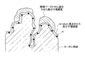
- FIG. 2 shows a schematic diagram of a catalyst-supporting carrier, which is disclosed in Patent Document 3, comprising a catalyst-supporting carbon, an electrolyte polymer polymerized in-situ, and an electrolyte polymer mixed in a catalyst paste.
- a cathode electrode for a fuel cell is manufactured by performing steps S11 to S15.
- the polymerizable electrolyte precursor (1), the polymerizable spacer precursor (2), and the first solvent (3) are mixed to prepare the platinum elution suppressing material (4).
- the polymerizable spacer precursor (2) has an arbitrary configuration.
- the polymerizable electrolyte precursor (1) is a low molecular compound having both a sulfonic acid group that is a proton acidic functional group and a polycondensable functional group in the same molecule.
- the proton acidic functional group is a functional group having a function of supplying protons onto the platinum catalyst surface where oxygen reduction reaction proceeds. Since the platinum elution suppressing material (4) needs to have a function of supplying protons onto the surface of the platinum catalyst, it contains at least the polymerizable electrolyte precursor (1) as a constituent element.
- the polycondensable functional group refers to a functional group that undergoes a polycondensation reaction by heating or reduced pressure.
- a silicon group having a hydroxyl group or an alkoxyl group is particularly preferable.
- a preferred silicon group is specifically a silicon group represented by the formula 1: (R 1 O) 3 Si— (wherein R 1 represents a hydrogen atom or an alkyl group having 1 to 4 carbon atoms).
- the platinum elution inhibiting material (4) has a polycondensable functional group represented by (R 1 O) 3 Si—, it can be polymerized in step S12 described later to form a polymer. In the polymerization, siloxane bonds are formed by bonding silicon atoms through oxygen atoms, and water or R 1 OH is released.
- Examples of the alkyl group having 1 to 4 carbon atoms in Formula 1 are a methyl group, an ethyl group, an n-propyl group, an isopropyl group, an n-butyl group, or a t-butyl group. From the viewpoint of high reactivity and easy removal after polymerization, the alkyl group having 1 to 4 carbon atoms in Formula 1 is preferably an ethyl group.
- the platinum elution suppressing material (4) is specifically represented by the formula: (R 1 O) 3 Si—R 2 —SO 3 H (wherein R 1 represents a hydrogen atom or an alkyl group having 1 to 4 carbon atoms). , R 2 represents an alkylene group having 1 to 15 carbon atoms). Three R 1 present in one molecule may be the same or different.
- the alkylene group represented by R 2 can be appropriately selected from alkylene groups having 1 to 15 carbon atoms. This alkylene group may be chain-like or branched. R 2 is preferably an alkylene group having 2 to 10 carbon atoms. When R 2 has 2 to 10 carbon atoms, the amount of sulfonic acid group (EW value) of the platinum elution suppressing material (4) obtained can be controlled.
- EW value sulfonic acid group
- the first solvent (3) is used for dissolving the platinum elution suppressing material (4) and / or the polymerizable spacer precursor (2).
- the first solvent is preferably a polar solvent so as to dissolve the platinum elution suppressing material (4) and / or the polymerizable spacer precursor (2).
- Specific examples of the first solvent are acetone, alcohols having 1 to 4 carbon atoms (methanol, ethanol, propanol, butanol), dimethylacetamide, ethyl acetate, butyl acetate, or tetrahydrofuran.
- the first solvent (3) one type of solvent may be used, or a plurality of types of solvents may be used in combination.
- the amount of the first solvent used is not particularly limited as long as the platinum elution suppressing material (4) and / or the polymerizable spacer precursor (2) can be dissolved.
- step S12 the catalyst powder (5), the platinum elution inhibiting material (4), and the second solvent (6) are mixed to prepare the first liquid (7).
- the mixing method is not particularly limited.
- the platinum elution suppressing material (4) in a low molecular state (not polymerized) is uniformly and uniformly disposed in the micropores of the catalyst powder (5).
- the second solvent (6) is used for ensuring the dispersibility of the first liquid (7) and adjusting the viscosity.
- the second solvent (6) is preferably a polar solvent so that the platinum elution suppressing material (4) and the catalyst powder (5) can be dissolved and dispersed.
- the same solvent as the first solvent (3) can be used.
- the catalyst powder (5) is a powder provided with metal catalyst particles on the surface of a conductive carrier, which is used in an electrode of a fuel cell, in particular, a polymer electrolyte fuel cell. Particles that catalyze the reaction at the cathode where oxygen and electrons react to produce water.
- a specific example of the catalyst powder (5) is platinum nanoparticles.
- the average particle diameter of the platinum nanoparticles is generally about 1 to 5 nm, and the specific surface area is about 50 to 200 m 2 / g.
- the particle size of the platinum nanoparticles used for the fuel cell is 2 to 3 nm or less. However, with such a particle size, platinum is easily eluted under proton acidic conditions, and the catalyst stability is extremely low.
- the conductive carrier refers to a porous carrier that supports catalyst particles. Since the porous carrier has a role of conducting electrons to the catalyst particles, it needs to have conductivity.
- a specific example of the conductive carrier is porous carbon particles. Porous carbon particles have pores having a minimum size of several nm in diameter. The average particle diameter of the porous carbon particles is larger than the average particle diameter of the catalyst particles, usually about 20 to 100 nm, and the specific surface area is about 100 to 1000 m 2 / g.
- organic polymer electrolytes are generally used to form planar electrodes and bind them to the surface of gas diffusion layers such as polymer electrolyte membranes, carbon paper, or carbon cloth. Is used.
- a mixing method at the time of preparing the first liquid a known method using a planetary ball mill, a bead mill or a homogenizer can be used, but the mixing method is not limited to these methods. It is preferable to prevent the first solvent or the second solvent from being oxidized by being combined with dissolved oxygen by the action of the catalyst powder. For this reason, it is preferable that preparation of a 1st liquid is performed under inert gas.
- the platinum elution suppressing material (4) only the polymerizable electrolyte precursor (1) may be used. However, it is preferable that the polymerizable electrolyte precursor (1) and the polymerizable spacer precursor (2) are used in combination in order to control the amount of the sulfonic acid group of the obtained polymer.
- the polymerizable spacer precursor (2) is copolymerizable with the polymerizable electrolyte precursor (1), the copolymer obtained by copolymerizing with the polymerizable electrolyte precursor (1) (Ie, platinum elution suppressing material (4)).
- the polymerizable spacer precursor (2) is a polymerizable compound having a polycondensable functional group without having a sulfonic acid group which is a proton acidic functional group.
- the polymerizable spacer precursor (2) has the formula 2: (R 3 O) m SiR 4 n (wherein R 3 represents a hydrogen atom or an alkyl group having 1 to 4 carbon atoms, and R 4 Represents an alkyl group having 1 to 10 carbon atoms, m represents 2, 3 or 4, and n represents 0, 1 or 2, provided that the sum of m and n is 4. It is. 2 to 4 R 3 present in Formula 2 may be the same or different. When two R 4 are present in Formula 2, the two R 4 may be the same or different. Only one type of compound may be used for the polymerizable spacer precursor (2), or a plurality of types of compounds may be used in combination.
- Examples of the alkyl group having 1 to 4 carbon atoms representing R 3 are, like R 1 , methyl group, ethyl group, n-propyl group, isopropyl group, n-butyl group, or t-butyl group.
- R 3 is preferably a methyl group because of its high reactivity and ease of removal after polymerization.
- R 4 is an alkyl group having 1 to 10 carbon atoms, and may be linear or branched. R 4 is selected in consideration of the structure of the polymerizable electrolyte precursor (1) or the amount of the polymerizable spacer precursor (2) used. R 4 is not particularly limited as long as the obtained platinum elution suppressing material (4) has a sulfonic acid group amount capable of suppressing the elution of platinum without inhibiting the catalytic reaction.
- the mixing ratio of the polymerizable electrolyte precursor (1) and the polymerizable spacer precursor (2) is determined by copolymerization. It can be determined as appropriate in consideration of the EW value and power generation characteristics of the platinum elution suppression layer (8) to be obtained, which will be described later.
- the mixing ratio of the polymerizable electrolyte precursor (1) and the polymerizable spacer precursor (2) is preferably in the range of 1: 0.25 to 10, and in the range of 1: 0.5 to 8 in terms of molar ratio. It is more preferable that
- EW is an abbreviation of “Equivalent Weight” and represents the weight of the dry electrolyte membrane per mole of sulfonic acid group. The smaller the EW value, the greater the proportion of sulfonic acid groups contained in the electrolyte.
- the platinum elution suppression layer (8) formed in the present invention preferably has an EW value that is too large in order to ensure both the stability of the platinum catalyst and the power generation characteristics of the cathode electrode. Since the polymer electrolyte layer of the fuel cell cathode electrode of the present invention preferably has an EW value of 1500 or less, the polymerizable electrolyte precursor (1) and the polymerizable spacer precursor so that the EW value is 1500 or less. The mixing ratio with the body (2) is preferably adjusted.
- the polymerizable spacer precursor (2) has an arbitrary configuration and may not be used.
- the structure of the lipophilic moiety with platinum dissolution inhibiting material (4) e.g., number of carbon atoms of the alkylene group R 2 by controlling the sulfonic acid group amount A controlled platinum elution suppression layer (5) may be formed.
- the water repellency of the platinum elution suppressing layer is determined by the structure of the polymerizable electrolyte precursor (1) and the polymerizable spacer precursor (2) constituting the platinum elution suppressing material (4), or the polymerizable electrolyte precursor (1) and polymerization. It is controlled by the mixing ratio of the conductive spacer precursor (2).
- the first liquid (7) is subjected to a pressure reduction treatment or a heat drying treatment, whereby the platinum elution suppressing material (4) contained in the first liquid (7) is polycondensed. It changes to a platinum elution suppression layer (8).
- a platinum elution suppression layer (8) coats platinum nanoparticles that are catalyst particles, thereby generating a suppression layer-coated catalyst (9).
- the second liquid (12) is produced by mixing the suppression layer-covered catalyst (9), the polymer electrolyte (10), and the third solvent (11).
- the polymer electrolyte (10) a perfluoroalkylsulfonic acid polymer that is generally used in a catalyst electrode for a fuel cell can be used, but any electrolyte material having proton conductivity comparable to this can be used.
- the third solvent (11) may use the same solvent as the first solvent (3) or the second solvent (6).
- the third solvent (11) one type of solvent may be used, or a plurality of types of solvents may be used in combination.
- step S16 the second liquid (12) obtained in S15 is applied onto the polymer electrolyte film as a base material, and the solvent is removed by a drying treatment, whereby the suppression layer-coated catalyst (9). And a cathode electrode (13) for a fuel cell comprising a polymer electrolyte (10).
- the second liquid (12) is directly applied and dried on an electrolyte film composed of a perfluorosulfonic acid polymer such as Nafion (registered trademark, product name manufactured by DuPont), thereby the electrolyte film.
- the suppression layer-covered catalyst (9) can be brought into close contact with the surface to form a fuel cell cathode electrode (13).
- the cathode electrode (13) for the fuel cell manufactured in steps S11 to S16 is coated with platinum nanoparticles as the catalyst powder (5) by the platinum elution suppression layer (8), and further the platinum elution suppression layer (8 ) On the outside of the polymer electrolyte (10).
- a sufficient amount of protons produced at the anode electrode are supplied to the majority of the catalyst surface present in the cathode electrode.
- deterioration of the platinum nanocatalyst (catalyst metal) associated with acid elution can be suppressed while exhibiting high power generation characteristics.
- the fuel cell cathode electrode produced according to the present invention is disposed so as to face the anode electrode through a polymer electrolyte membrane such as a perfluorosulfonic acid electrolyte membrane, and is disposed outside the cathode electrode and the anode electrode.
- a fuel cell is configured by arranging the separator so as to sandwich the fuel cell.
- Solubility of Platinum Elution Suppressing Layer in Solvent first, a polymerizable electrolyte precursor having a sulfonic acid group and a (R 1 O) 3 Si— group was diluted in an organic solvent. Thereafter, a low molecular weight material insoluble in water was added and mixed as a polymerizable spacer precursor, and a platinum elution suppressing material was prepared. The catalyst powder and the organic solvent were mixed with the solution containing the platinum elution suppressing material, and the solvent was removed by a drying process under reduced pressure. The platinum elution suppression material was copolymerized, and a platinum elution suppression layer was obtained on the surface of the catalyst powder.
- the specific experimental procedure is as follows. 10 mmol of a trihydroxyalkylsilane compound having a sulfonic acid group ((HO) 3 Si— (CH 2 ) 3 —SO 3 H, 30 wt% aqueous solution, manufactured by Gelest) was used as a polymerizable electrolyte precursor, and t-BuOH And diluted to a 10 wt% solution. Subsequently, (MeO) 3 Si—Me 10 mmol was added as a polymerizable spacer precursor and stirred for 15 minutes. Further, t-BuOH was added and mixed to prepare a platinum elution suppressing material as a colorless transparent solution.
- a trihydroxyalkylsilane compound having a sulfonic acid group ((HO) 3 Si— (CH 2 ) 3 —SO 3 H, 30 wt% aqueous solution, manufactured by Gelest) was used as a polymerizable electrolyte precursor, and t-BuOH And
- the polymerization reaction proceeds by gradually removing the solvent under reduced pressure.
- a water-insoluble polysiloxane solid (corresponding to a platinum elution suppression layer) is obtained. It was.
- the polysiloxane solid has a siloxane (Si—O—Si) skeleton.
- the polysiloxane solid was immersed in water and stirred overnight. The supernatant was removed and water was removed under reduced pressure, but no precipitation of the polysiloxane compound was confirmed.
- the solid-state NMR measurement was performed on the polysiloxane solid, the signal peaks of 13 C-DDMAS-NMR (single pulse & 1H decouple) and 29 Si-CPMAS-NMR (1H ⁇ 13C cross polarization & 1H decouple) were measured.
- the chemical shift value was in good agreement with the theoretical value expected from its molecular structure, confirming that the polysiloxane solid was a copolymer having the target molecular structure.
- solvents that can be used in preparing the platinum elution inhibiting material described above are acetone, lower alcohols such as ethanol, or dimethylacetamide other than t-BuOH.
- electrodes A ⁇ G for a fuel cell 1.
- a method for producing a cathode electrode for a fuel cell using the platinum elution suppressing material obtained by the method described in the section of the solubility of the platinum elution suppressing layer in a solvent will be described below.
- platinum elution suppression materials were prepared with the combinations and composition ratios of the compounds shown in Table 1. These eleven types of platinum elution control materials are (HO) 3 Si— (CH 2 ) 3 —SO 3 H, which is a polymerizable electrolyte precursor, and (MeO) 3 Si—R (R), which is a polymerizable spacer precursor. : Alkyl group, Me: methyl group) in a predetermined molar ratio. 5 g of ultrapure water and 6.5 g of t-BuOH were added as a first solvent to 1 g of a mixture of these two types of monomers as a solid content, and the first solution was adjusted to 8% weight concentration.
- an appropriate molar composition having current-voltage characteristics is selected as the cathode electrode.
- the polymerizable electrolyte precursor and the polymerizable spacer precursor contained in these platinum elution suppressing materials are solvated in a low molecular state.
- a platinum-supported carbon (TEC10E50E) manufactured by Tanaka Kikinzoku Co. which is a catalyst powder, eleven types of platinum elution control materials, and t-BuOH as a second solvent are mixed to prepare a first liquid. It was.
- the case where the electrode A is manufactured will be described.
- 5 g of catalyst-powder platinum-supported carbon was weighed into a polypropylene beaker, 5 g of t-BuOH was added, and the mixture was stirred and mixed so that t-BuOH could be used as a whole.
- the catalyst powder used here has a porous structure in which platinum nanoparticles having an average particle diameter of about 2 to 3 nm are supported on the surface of carbon fine powder (carbon black).
- the first liquid for producing the electrodes B to G was prepared in the same manner as the electrode A so that the weight composition ratio was 5 to 40%.
- the weight composition ratio was optimized in view of the power generation characteristics of each electrode finally manufactured.
- the first liquid was stirred at room temperature under reduced pressure to remove most of the solvent.
- the platinum elution suppression material changed into a platinum elution suppression layer with the progress of the polycondensation reaction. Furthermore, by performing a reduced pressure treatment at 1 Torr and 80 ° C. for 2 hours, a suppression layer-coated catalyst having a platinum elution suppression layer provided in the vicinity of the platinum particles was synthesized.
- a spray drying method or a freeze drying method may also be used as a method for removing the solvent contained in the first liquid. The method for removing the solvent is selected according to the required material shape of the catalyst.
- a second liquid was prepared by kneading the suppression layer-coated catalyst, the electrolyte, and the third solvent. Specifically, 6 g of Nafion (registered trademark) dispersion (10% by weight, manufactured by Aldrich), which is a perfluorocarbon sulfonic acid polymer electrolyte, was added to 1.15 g of the suppression layer coating catalyst, and further for viscosity adjustment.
- a catalyst electrode solution for cathode electrode A was prepared by adding water and alcohol and stirring.
- the anode electrode solution was prepared by the following method. After 2 g of platinum-supporting carbon (TEC10E50E, manufactured by Tanaka Kikinzoku) was dispersed in 10 g of Nafion (registered trademark) dispersion (10 wt%, manufactured by Aldrich), water and ethanol were further added to adjust the viscosity, A second liquid was prepared.
- platinum-supporting carbon TEC10E50E, manufactured by Tanaka Kikinzoku
- the weight of the polymer electrolyte added to the suppression layer coating catalyst and the catalyst powder was determined in consideration of the conditions of the material to be the second liquid and the power generation characteristics as the catalyst electrode.
- the weight of the polymer electrolyte added to the suppression layer coating catalyst and the catalyst powder is not limited to the weight of the example.
- the catalyst electrode solution for the cathode electrode A was applied to a polymer electrolyte membrane Nafion (registered trademark) NR-211 (manufactured by DuPont) to produce a cathode electrode A as a membrane-electrode assembly (MEA).
- the catalyst electrode paste for the anode electrode was applied to a polymer electrolyte membrane Nafion (registered trademark) NR-211 (manufactured by DuPont) to produce an anode electrode which is a membrane-electrode assembly (MEA).
- the fuel cell single cell was comprised from the cathode electrode A and the anode electrode.
- the second liquid was die-coated on the substrate so that the amount of platinum supported on the cathode electrode was 0.3 mg / cm 2 .
- the catalyst electrode paste was die-coated on the base material so that the platinum loading of the anode electrode was 0.2 mg / cm 2 .
- the cathode electrode and the anode electrode were prepared by die-coating the catalyst electrode paste on the polymer electrolyte membrane in accordance with the general method for manufacturing the fuel cell MEA. Is not limited to this method.
- the polymerizable electrolyte precursor and the polymerizable spacer precursor shown in Table 1 are mixed at the molar ratio shown in Table 1 to prepare the second liquid, and the cathode electrodes B ⁇ K was made.
- a fuel cell single cell was constructed from the cathode electrodes B to K and the anode electrode.
- Comparative Example 1 Production of Comparative Electrode A comparative electrode was produced using a perfluorocarbon sulfonic acid electrolyte having an EW value of 1000. Specifically, 2 g of platinum-supporting carbon (TEC10E50E, manufactured by Tanaka Kikinzoku Co., Ltd.) was dispersed in 10 g of Nafion (registered trademark) dispersion (10% by weight, manufactured by Aldrich), and then water and ethanol were further added. Thus, the viscosity was adjusted and a paste was prepared. A cathode electrode, which is an MEA, was produced using a polymer electrolyte membrane Nafion (registered trademark) NR-211 (manufactured by DuPont) and the paste. The cathode electrode and the anode electrode described above were used to form a fuel cell single cell.
- TEC10E50E platinum-supporting carbon
- the paste was die-coated on the base material so that the platinum loading of the reference electrode was 0.3 mg / cm 2 .
- Hydrogen gas (65 ° C., 100% RH) is supplied to the anode electrode for the fuel cell single cell having the catalytic reaction area (ECA) change electrodes A to G of the fuel cell electrode and the comparison electrode as the cathode electrode.
- ECA catalytic reaction area
- the catalyst deterioration test was performed while nitrogen gas (65 ° C., 100% RH) was supplied to the cathode electrode.
- the catalyst degradation test protocol was as follows. A total of 5000 cycles of potential load fluctuations of 6 seconds and 1 cycle of 0.6 V: 3 seconds and 1.0 V: 3 seconds were performed on the cathode electrode. And about the cathode electrode before and behind a test, the electrochemical surface area (ECA) of platinum was measured by the cyclic voltammetry method, and ECA retention after the test was computed. Table 1 shows the ECA (relative value with an initial value of 100%) after the catalyst deterioration test for each electrode.
- ECA electrochemical surface area
- the ECA decreased to half of the initial value.
- the electrodes A to G which were prepared by previously providing a platinum elution suppressing layer and mixed with a polymer electrolyte, showed a high ECA retention rate of 70 to 90%.
- the current-voltage characteristics of the cathode electrodes A to G provided with the platinum elution suppression layer were equal to or higher than those of the cathode electrode without the platinum elution suppression layer.
- the cathode electrode for a fuel cell produced in the example can secure long-term stability while improving the initial characteristics of the fuel cell.
- the cathode electrode manufactured by the method for manufacturing a cathode electrode for a fuel cell of the present invention can maintain the power generation characteristics of the fuel cell due to the catalyst deterioration suppressing effect for a long time.
- the method for producing a cathode electrode for a fuel cell according to the present invention is effective in reducing the amount of noble metal electrode particles and catalyst particles finely dispersed in a porous structure and ensuring reliability, and is a stable and inexpensive fuel.
- a battery cathode electrode may be manufactured.
- the fuel cell cathode electrode, the manufacturing method thereof, and the fuel cell including the fuel cell cathode electrode are useful in the technical field of fuel cells.
- Patent Document 3 discloses the following.
- an electrode manufacturing method that sufficiently secures a three-phase interface where reaction gas, catalyst, and electrolyte meet in carbon and improves the utilization efficiency of the catalyst.
- Example 12 of Patent Document 5 discloses the following.
- Example 12 Carbon catalyst-supported carbon black (TEC10A30E; Tanaka Kikinzoku Co., Ltd.) 5.0 g, tetraethoxysilane 5.0 g, and 3- (trihydroxysilyl) -1-propanesulfonic acid 33% aqueous solution 4.0 g in isopropyl alcohol 15 g homogenizer was uniformly dispersed. This liquid material was coated on both sides of the proton conductive membrane with a roll coater so as to have a thickness of 30 ⁇ m.
- TEC10A30E Tanaka Kikinzoku Co., Ltd.
- a carbon paper TGP-H-120 (manufactured by Toray Industries, Inc.) was attached to the film coated with the liquid, and pressed with a press machine at a pressure of 5.0 N / cm 2 for 2 hours, and then at 80 ° C.
- the membrane-electrode assembly was obtained by putting it in a constant temperature and humidity chamber of 95% RH for 12 hours.
- Example 2 An evaluation cell was prepared and evaluated in the same manner as in Example 1. As a result, the maximum output was 35 (mW / cm 2 ), the limiting current density was 0.23 (A / cm 2 ), and the adhesion state was good.
Landscapes
- Chemical & Material Sciences (AREA)
- Chemical Kinetics & Catalysis (AREA)
- Electrochemistry (AREA)
- General Chemical & Material Sciences (AREA)
- Engineering & Computer Science (AREA)
- Manufacturing & Machinery (AREA)
- Inert Electrodes (AREA)
- Fuel Cell (AREA)
Abstract
Priority Applications (3)
| Application Number | Priority Date | Filing Date | Title |
|---|---|---|---|
| JP2011528136A JP4897119B2 (ja) | 2010-03-05 | 2011-03-01 | 燃料電池用カソード電極の製造方法及び燃料電池用カソード電極 |
| CN2011800029945A CN102484258A (zh) | 2010-03-05 | 2011-03-01 | 燃料电池用阴极的制造方法以及燃料电池用阴极 |
| US13/306,134 US20120135320A1 (en) | 2010-03-05 | 2011-11-29 | Manufacturing method of cathode electrode for fuel cells and cathode electrode for fuel cells |
Applications Claiming Priority (2)
| Application Number | Priority Date | Filing Date | Title |
|---|---|---|---|
| JP2010-049706 | 2010-03-05 | ||
| JP2010049706 | 2010-03-05 |
Related Child Applications (1)
| Application Number | Title | Priority Date | Filing Date |
|---|---|---|---|
| US13/306,134 Continuation US20120135320A1 (en) | 2010-03-05 | 2011-11-29 | Manufacturing method of cathode electrode for fuel cells and cathode electrode for fuel cells |
Publications (1)
| Publication Number | Publication Date |
|---|---|
| WO2011108252A1 true WO2011108252A1 (fr) | 2011-09-09 |
Family
ID=44541922
Family Applications (1)
| Application Number | Title | Priority Date | Filing Date |
|---|---|---|---|
| PCT/JP2011/001180 Ceased WO2011108252A1 (fr) | 2010-03-05 | 2011-03-01 | Procédé de fabrication d'une électrode de cathode de pile à combustible et électrode de cathode de pile à combustible |
Country Status (4)
| Country | Link |
|---|---|
| US (1) | US20120135320A1 (fr) |
| JP (1) | JP4897119B2 (fr) |
| CN (1) | CN102484258A (fr) |
| WO (1) | WO2011108252A1 (fr) |
Families Citing this family (4)
| Publication number | Priority date | Publication date | Assignee | Title |
|---|---|---|---|---|
| JP6295993B2 (ja) * | 2015-04-13 | 2018-03-20 | トヨタ自動車株式会社 | 燃料電池用電極の製造方法 |
| KR102855179B1 (ko) * | 2020-03-13 | 2025-09-03 | 현대자동차주식회사 | 용출된 전이금속이 제거된 연료전지용 촉매 잉크의 제조방법 |
| CN112436167B (zh) * | 2020-11-17 | 2021-10-12 | 中国科学院兰州化学物理研究所 | 一种直接式多醚类化合物燃料电池及系统 |
| CN115425246B (zh) * | 2022-09-01 | 2025-04-29 | 苏州工业职业技术学院 | 生物质固定铂纳米颗粒催化剂层的制备 |
Citations (7)
| Publication number | Priority date | Publication date | Assignee | Title |
|---|---|---|---|---|
| JPH07254419A (ja) * | 1994-03-15 | 1995-10-03 | Tanaka Kikinzoku Kogyo Kk | 高分子電解質型電気化学セル用電極及びその製造方法 |
| WO2003026051A1 (fr) * | 2001-09-11 | 2003-03-27 | Sekisui Chemical Co., Ltd. | Ensemble membrane-electrode, son procede de production, et pile a combustible a polymere solide la comportant |
| JP2003178770A (ja) * | 2002-12-26 | 2003-06-27 | Sekisui Chem Co Ltd | 膜−電極接合体、その製造方法及びそれを用いた固体高分子電解質型または直接メタノール型燃料電池 |
| WO2006118346A1 (fr) * | 2005-04-28 | 2006-11-09 | Canon Kabushiki Kaisha | Couche catalytique hydrophobe pour pile a combustible de polymere solide, procede pour la produire, pile a combustible de polymere solide et procede pour la fabriquer |
| WO2007066821A1 (fr) * | 2005-12-09 | 2007-06-14 | Toyota Jidosha Kabushiki Kaisha | Procede pour la production d'electrodes de piles a combustible et piles a combustible a electrolyte polymere comportant des electrodes de piles a combustible |
| JP2009170175A (ja) * | 2008-01-11 | 2009-07-30 | Toyota Motor Corp | 膜電極構造体及び燃料電池 |
| JP4531121B1 (ja) * | 2009-04-28 | 2010-08-25 | パナソニック株式会社 | 燃料電池用電極およびその製造方法、並びにこれを用いた燃料電池 |
Family Cites Families (10)
| Publication number | Priority date | Publication date | Assignee | Title |
|---|---|---|---|---|
| JP3564975B2 (ja) * | 1997-10-23 | 2004-09-15 | トヨタ自動車株式会社 | 燃料電池用電極および燃料電池用電極の製造方法 |
| WO2000011741A1 (fr) * | 1998-08-20 | 2000-03-02 | Matsushita Electric Industrial Co., Ltd. | Pile a combustible et procede de fabrication de celle-ci |
| DE60135080D1 (de) * | 2000-12-26 | 2008-09-11 | Asahi Glass Co Ltd | Festpolymer-Elektrolyt Material, flüssige Zusammensetzung, Festpolymer Brennstoffzelle und Fluorpolymer |
| US7241334B2 (en) * | 2002-05-23 | 2007-07-10 | Columbian Chemicals Company | Sulfonated carbonaceous materials |
| US20040137297A1 (en) * | 2002-12-26 | 2004-07-15 | Hitoshi Matsuoka | Ion exchange membrane and production process therefor |
| JP4613528B2 (ja) * | 2004-06-24 | 2011-01-19 | コニカミノルタホールディングス株式会社 | プロトン伝導性電解質膜とその製造方法、及び該プロトン伝導性電解質膜を用いた固体高分子型燃料電池 |
| JP2006054176A (ja) * | 2004-07-16 | 2006-02-23 | Sekisui Chem Co Ltd | 固体高分子形燃料電池用電極、固体高分子形燃料電池用電極の製造方法及び固体高分子形燃料電池 |
| CN100541888C (zh) * | 2004-09-03 | 2009-09-16 | 东丽株式会社 | 高分子电解质材料、高分子电解质部件、膜电极复合体和高分子电解质型燃料电池 |
| JP5013740B2 (ja) * | 2005-04-28 | 2012-08-29 | キヤノン株式会社 | 固体高分子型燃料電池の疎水性触媒層及びその製造方法、固体高分子型燃料電池及びその製造方法 |
| WO2010125618A1 (fr) * | 2009-04-28 | 2010-11-04 | パナソニック株式会社 | Electrode pour pile à combustible, procédé de fabrication de l'électrode et pile à combustible utilisant l'électrode |
-
2011
- 2011-03-01 WO PCT/JP2011/001180 patent/WO2011108252A1/fr not_active Ceased
- 2011-03-01 CN CN2011800029945A patent/CN102484258A/zh active Pending
- 2011-03-01 JP JP2011528136A patent/JP4897119B2/ja not_active Expired - Fee Related
- 2011-11-29 US US13/306,134 patent/US20120135320A1/en not_active Abandoned
Patent Citations (7)
| Publication number | Priority date | Publication date | Assignee | Title |
|---|---|---|---|---|
| JPH07254419A (ja) * | 1994-03-15 | 1995-10-03 | Tanaka Kikinzoku Kogyo Kk | 高分子電解質型電気化学セル用電極及びその製造方法 |
| WO2003026051A1 (fr) * | 2001-09-11 | 2003-03-27 | Sekisui Chemical Co., Ltd. | Ensemble membrane-electrode, son procede de production, et pile a combustible a polymere solide la comportant |
| JP2003178770A (ja) * | 2002-12-26 | 2003-06-27 | Sekisui Chem Co Ltd | 膜−電極接合体、その製造方法及びそれを用いた固体高分子電解質型または直接メタノール型燃料電池 |
| WO2006118346A1 (fr) * | 2005-04-28 | 2006-11-09 | Canon Kabushiki Kaisha | Couche catalytique hydrophobe pour pile a combustible de polymere solide, procede pour la produire, pile a combustible de polymere solide et procede pour la fabriquer |
| WO2007066821A1 (fr) * | 2005-12-09 | 2007-06-14 | Toyota Jidosha Kabushiki Kaisha | Procede pour la production d'electrodes de piles a combustible et piles a combustible a electrolyte polymere comportant des electrodes de piles a combustible |
| JP2009170175A (ja) * | 2008-01-11 | 2009-07-30 | Toyota Motor Corp | 膜電極構造体及び燃料電池 |
| JP4531121B1 (ja) * | 2009-04-28 | 2010-08-25 | パナソニック株式会社 | 燃料電池用電極およびその製造方法、並びにこれを用いた燃料電池 |
Also Published As
| Publication number | Publication date |
|---|---|
| US20120135320A1 (en) | 2012-05-31 |
| JP4897119B2 (ja) | 2012-03-14 |
| JPWO2011108252A1 (ja) | 2013-06-20 |
| CN102484258A (zh) | 2012-05-30 |
Similar Documents
| Publication | Publication Date | Title |
|---|---|---|
| EP3493311A1 (fr) | Ensemble membrane-électrode, son procédé de fabrication, et pile à combustible le comprenant | |
| US6911411B2 (en) | Catalyst agglomerates for membrane electrode assemblies | |
| CN103270630B (zh) | 阴极催化剂层、膜电极组件和聚合物电解质燃料电池及其制造方法 | |
| JP2013168368A (ja) | 燃料電池用高分子電解質膜、その製造方法及びそれを含む燃料電池システム | |
| KR20210085300A (ko) | 고내구성을 갖는 연료전지용 전극, 그 제조방법, 및 그것을 포함하는 막-전극 어셈블리 | |
| WO2017159820A1 (fr) | Pâte pour former une couche de catalyseur d'électrode et son procédé de fabrication, et procédés pour fabriquer un ensemble couche de catalyseur d'électrode de membrane, électrode à diffusion de gaz, pile à combustible à base de polymère solide et cellule d'électrolyse d'eau à base de polymère solide | |
| JP4897119B2 (ja) | 燃料電池用カソード電極の製造方法及び燃料電池用カソード電極 | |
| CN101140991B (zh) | 一种质子交换膜燃料电池电极催化层及其制备 | |
| JP4987857B2 (ja) | 重合体分散物及び電気触媒インク | |
| KR102199455B1 (ko) | 막-전극접합체 전극용 바인더, 이의 제조방법 및 이를 포함하는 막-전극접합체 및 고분자전해질 연료전지 | |
| KR100829060B1 (ko) | 이중 전극을 갖는 막-전극 바인더, 이의 제조방법 및 이를포함하는 연료 전지 | |
| JP5535773B2 (ja) | 固体高分子型燃料電池用膜−電極構造体 | |
| US8057960B2 (en) | Electrode for fuel cells and method for manufacturing the same, and fuel cell using the same | |
| JP4823583B2 (ja) | 燃料電池用高分子膜/電極接合体及びこれを含む燃料電池 | |
| US7960073B2 (en) | Membrane electrode assembly for fuel cell and fuel cell system including the same | |
| KR20100069494A (ko) | 연료전지용 프로톤 전도체, 이를 포함하는 연료전지용 전극및 이를 이용한 연료전지 | |
| KR20220133571A (ko) | 연료전지용 고분자 전해질 막 및 이를 포함하는 연료전지 | |
| JP2011222350A (ja) | 酸素還元反応電極の製造方法、並びにこれを用いた燃料電池 | |
| JP2011187240A (ja) | 燃料電池用電極の製造方法、並びにこれを用いた燃料電池 | |
| JP4531121B1 (ja) | 燃料電池用電極およびその製造方法、並びにこれを用いた燃料電池 | |
| KR101866872B1 (ko) | 고분자 전해질 연료전지용 막-전극 접합체 및 그 제조방법 | |
| JP2010238415A (ja) | 触媒ペースト調製方法 | |
| CN121366915A (zh) | 膜电极接合体和燃料电池 | |
| JP2026013819A (ja) | 膜電極接合体 | |
| WO2010119492A1 (fr) | Procédé de fabrication d'électrode pour piles à combustible |
Legal Events
| Date | Code | Title | Description |
|---|---|---|---|
| WWE | Wipo information: entry into national phase |
Ref document number: 201180002994.5 Country of ref document: CN |
|
| WWE | Wipo information: entry into national phase |
Ref document number: 2011528136 Country of ref document: JP |
|
| 121 | Ep: the epo has been informed by wipo that ep was designated in this application |
Ref document number: 11750365 Country of ref document: EP Kind code of ref document: A1 |
|
| NENP | Non-entry into the national phase |
Ref country code: DE |
|
| 122 | Ep: pct application non-entry in european phase |
Ref document number: 11750365 Country of ref document: EP Kind code of ref document: A1 |