WO2011108266A1 - Système de pile à combustible et procédé de fonctionnement de celui-ci - Google Patents
Système de pile à combustible et procédé de fonctionnement de celui-ci Download PDFInfo
- Publication number
- WO2011108266A1 WO2011108266A1 PCT/JP2011/001224 JP2011001224W WO2011108266A1 WO 2011108266 A1 WO2011108266 A1 WO 2011108266A1 JP 2011001224 W JP2011001224 W JP 2011001224W WO 2011108266 A1 WO2011108266 A1 WO 2011108266A1
- Authority
- WO
- WIPO (PCT)
- Prior art keywords
- water
- water tank
- amount
- fuel cell
- tank
- Prior art date
- Legal status (The legal status is an assumption and is not a legal conclusion. Google has not performed a legal analysis and makes no representation as to the accuracy of the status listed.)
- Ceased
Links
Images








Classifications
-
- H—ELECTRICITY
- H01—ELECTRIC ELEMENTS
- H01M—PROCESSES OR MEANS, e.g. BATTERIES, FOR THE DIRECT CONVERSION OF CHEMICAL ENERGY INTO ELECTRICAL ENERGY
- H01M8/00—Fuel cells; Manufacture thereof
- H01M8/04—Auxiliary arrangements, e.g. for control of pressure or for circulation of fluids
- H01M8/04298—Processes for controlling fuel cells or fuel cell systems
- H01M8/04313—Processes for controlling fuel cells or fuel cell systems characterised by the detection or assessment of variables; characterised by the detection or assessment of failure or abnormal function
- H01M8/0438—Pressure; Ambient pressure; Flow
- H01M8/04417—Pressure; Ambient pressure; Flow of the coolant
-
- H—ELECTRICITY
- H01—ELECTRIC ELEMENTS
- H01M—PROCESSES OR MEANS, e.g. BATTERIES, FOR THE DIRECT CONVERSION OF CHEMICAL ENERGY INTO ELECTRICAL ENERGY
- H01M8/00—Fuel cells; Manufacture thereof
- H01M8/04—Auxiliary arrangements, e.g. for control of pressure or for circulation of fluids
- H01M8/04082—Arrangements for control of reactant parameters, e.g. pressure or concentration
- H01M8/04089—Arrangements for control of reactant parameters, e.g. pressure or concentration of gaseous reactants
- H01M8/04119—Arrangements for control of reactant parameters, e.g. pressure or concentration of gaseous reactants with simultaneous supply or evacuation of electrolyte; Humidifying or dehumidifying
- H01M8/04156—Arrangements for control of reactant parameters, e.g. pressure or concentration of gaseous reactants with simultaneous supply or evacuation of electrolyte; Humidifying or dehumidifying with product water removal
-
- H—ELECTRICITY
- H01—ELECTRIC ELEMENTS
- H01M—PROCESSES OR MEANS, e.g. BATTERIES, FOR THE DIRECT CONVERSION OF CHEMICAL ENERGY INTO ELECTRICAL ENERGY
- H01M8/00—Fuel cells; Manufacture thereof
- H01M8/04—Auxiliary arrangements, e.g. for control of pressure or for circulation of fluids
- H01M8/04298—Processes for controlling fuel cells or fuel cell systems
- H01M8/04313—Processes for controlling fuel cells or fuel cell systems characterised by the detection or assessment of variables; characterised by the detection or assessment of failure or abnormal function
- H01M8/0438—Pressure; Ambient pressure; Flow
- H01M8/0441—Pressure; Ambient pressure; Flow of cathode exhausts
-
- H—ELECTRICITY
- H01—ELECTRIC ELEMENTS
- H01M—PROCESSES OR MEANS, e.g. BATTERIES, FOR THE DIRECT CONVERSION OF CHEMICAL ENERGY INTO ELECTRICAL ENERGY
- H01M8/00—Fuel cells; Manufacture thereof
- H01M8/04—Auxiliary arrangements, e.g. for control of pressure or for circulation of fluids
- H01M8/04298—Processes for controlling fuel cells or fuel cell systems
- H01M8/04313—Processes for controlling fuel cells or fuel cell systems characterised by the detection or assessment of variables; characterised by the detection or assessment of failure or abnormal function
- H01M8/04664—Failure or abnormal function
- H01M8/04686—Failure or abnormal function of auxiliary devices, e.g. batteries, capacitors
-
- H—ELECTRICITY
- H01—ELECTRIC ELEMENTS
- H01M—PROCESSES OR MEANS, e.g. BATTERIES, FOR THE DIRECT CONVERSION OF CHEMICAL ENERGY INTO ELECTRICAL ENERGY
- H01M8/00—Fuel cells; Manufacture thereof
- H01M8/04—Auxiliary arrangements, e.g. for control of pressure or for circulation of fluids
- H01M8/04298—Processes for controlling fuel cells or fuel cell systems
- H01M8/04694—Processes for controlling fuel cells or fuel cell systems characterised by variables to be controlled
- H01M8/04746—Pressure; Flow
- H01M8/04761—Pressure; Flow of fuel cell exhausts
-
- H—ELECTRICITY
- H01—ELECTRIC ELEMENTS
- H01M—PROCESSES OR MEANS, e.g. BATTERIES, FOR THE DIRECT CONVERSION OF CHEMICAL ENERGY INTO ELECTRICAL ENERGY
- H01M8/00—Fuel cells; Manufacture thereof
- H01M8/04—Auxiliary arrangements, e.g. for control of pressure or for circulation of fluids
- H01M8/04298—Processes for controlling fuel cells or fuel cell systems
- H01M8/04694—Processes for controlling fuel cells or fuel cell systems characterised by variables to be controlled
- H01M8/04746—Pressure; Flow
- H01M8/04768—Pressure; Flow of the coolant
-
- H—ELECTRICITY
- H01—ELECTRIC ELEMENTS
- H01M—PROCESSES OR MEANS, e.g. BATTERIES, FOR THE DIRECT CONVERSION OF CHEMICAL ENERGY INTO ELECTRICAL ENERGY
- H01M8/00—Fuel cells; Manufacture thereof
- H01M8/04—Auxiliary arrangements, e.g. for control of pressure or for circulation of fluids
- H01M8/04298—Processes for controlling fuel cells or fuel cell systems
- H01M8/04694—Processes for controlling fuel cells or fuel cell systems characterised by variables to be controlled
- H01M8/04955—Shut-off or shut-down of fuel cells
-
- H—ELECTRICITY
- H01—ELECTRIC ELEMENTS
- H01M—PROCESSES OR MEANS, e.g. BATTERIES, FOR THE DIRECT CONVERSION OF CHEMICAL ENERGY INTO ELECTRICAL ENERGY
- H01M8/00—Fuel cells; Manufacture thereof
- H01M8/04—Auxiliary arrangements, e.g. for control of pressure or for circulation of fluids
- H01M8/04007—Auxiliary arrangements, e.g. for control of pressure or for circulation of fluids related to heat exchange
- H01M8/04029—Heat exchange using liquids
-
- Y—GENERAL TAGGING OF NEW TECHNOLOGICAL DEVELOPMENTS; GENERAL TAGGING OF CROSS-SECTIONAL TECHNOLOGIES SPANNING OVER SEVERAL SECTIONS OF THE IPC; TECHNICAL SUBJECTS COVERED BY FORMER USPC CROSS-REFERENCE ART COLLECTIONS [XRACs] AND DIGESTS
- Y02—TECHNOLOGIES OR APPLICATIONS FOR MITIGATION OR ADAPTATION AGAINST CLIMATE CHANGE
- Y02E—REDUCTION OF GREENHOUSE GAS [GHG] EMISSIONS, RELATED TO ENERGY GENERATION, TRANSMISSION OR DISTRIBUTION
- Y02E60/00—Enabling technologies; Technologies with a potential or indirect contribution to GHG emissions mitigation
- Y02E60/30—Hydrogen technology
- Y02E60/50—Fuel cells
Definitions
- the present invention relates to a fuel cell system and an operation method thereof. More specifically, the present invention relates to a fuel cell system including a water tank and a water amount sensor and an operation method thereof.
- the fuel cell power generator used in the stationary cogeneration system is expected as a distributed power generator and a heat supply source.
- Conventional fuel cell power generators produce fuel from raw materials with a hydrogen generator and generate power with a cell stack.
- the heat generated during power generation can be used for hot water supply.
- the water that is generated at the same time is used for reactions when fuel is produced. For this reason, in the fuel cell power generator, it is important to effectively use water generated during power generation and to realize high reliability.
- the fuel cell system disclosed in Patent Document 1 includes a fuel cell, a water tank that stores water for cooling the fuel cell, and a controller, and the controller uses a water supply pump that supplies water to the water tank. If the water level detected by the first water level sensor is higher than the first water level even if the cumulative water discharge after the supply of water exceeds the first threshold, the water supply pump starts supplying water If the water level detected by the first water level sensor is less than the second water level even if the accumulated water supply amount after that becomes equal to or greater than the second threshold, or the water supply pump stops supplying water When the accumulated water discharge amount from is less than the third threshold value and the water level detected by the first water level sensor is equal to or lower than the third water level, an abnormal signal is transmitted.
- the present invention solves the above-described conventional problems, and an object of the present invention is to provide a fuel cell system and a method for operating the fuel cell system that can more reliably grasp an abnormality with a simpler configuration.
- a fuel cell system includes a fuel cell unit that generates power using a fuel gas and an oxidant gas, and moisture in the gas discharged from the fuel cell unit is condensed.
- a first water tank for storing at least one of condensed water, cooling water for cooling the fuel cell unit, and hot water for recovering heat from the fuel cell unit; the condensed water;
- a second water tank for storing at least one of cooling water and hot water, a first water sensor for detecting the amount of water in the first water tank, and a second water amount sensor for detecting the amount of water in the second water tank;
- a first water movement mechanism for moving water in the first water tank to the second water tank, and a control unit for controlling the first water movement mechanism, wherein the control Controls the first water movement mechanism so that water moves from the first water tank to the second water tank, and then the first water control mechanism before the start of the control of the first water control mechanism.
- the operation method of the fuel cell system of the present invention recovers the condensed water in which the moisture in the gas discharged from the fuel cell unit is condensed, the cooling water for cooling the fuel cell, and the heat from the fuel cell.
- Detecting the amount of water in a first water tank that stores at least one of hot water for storing with a first water amount sensor and storing at least one of the condensed water, the cooling water, and the hot water.
- the fuel cell system and the operation method thereof according to the present invention have an effect that the abnormality can be grasped more reliably with a simpler configuration by adopting the above configuration.
- FIG. 1 is a block diagram illustrating an example of a schematic configuration of the fuel cell system according to the first embodiment.
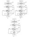
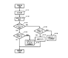
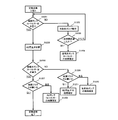
- FIG. 2 is a flowchart showing an example of the operation method of the fuel cell system according to the first embodiment.
- FIG. 2A shows a case where a determination operation is performed as an abnormal processing operation
- FIG. 2 (c) shows a case where the operation is stopped as an abnormality processing operation.
- FIG. 3 is a block diagram showing an example of a schematic configuration of the fuel cell system according to the first example of the first embodiment.
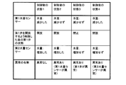
- FIG. 4 is a table showing an outline of determination in the fuel cell system in the first example of the first embodiment.
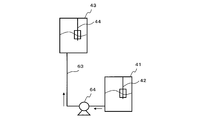
- FIG. 5 is a block diagram illustrating an example of a schematic configuration of the fuel cell system according to the second example of the first embodiment.
- FIG. 6 is a table showing an outline of determination in the fuel cell system in the second example of the first embodiment.
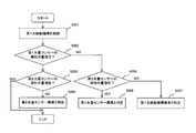
- FIG. 7 is a flowchart showing an example of an operation method of the fuel cell system in the first modification of the first embodiment.
- FIG. 8 is a block diagram illustrating an example of a schematic configuration of a fuel cell system according to a second modification of the first embodiment.
- FIG. 9 is a block diagram illustrating an example of a schematic configuration of a fuel cell system according to a third modification of the first embodiment.
- FIG. 10 is a block diagram illustrating an example of a schematic configuration of a fuel cell system according to a fourth modification of the first embodiment.
- FIG. 11 is a block diagram illustrating an example of a schematic configuration of a fuel cell system according to the second embodiment.
- FIG. 12 is a flowchart illustrating an example of an operation method of the initial operation process 1 in the second embodiment.
- FIG. 13 is a flowchart illustrating an example of the operation method of the initial operation step 2 in the second embodiment.
- FIG. 14 is a flowchart illustrating an example of an operation method of the initial operation process 3 in the second embodiment.
- FIG. 15 is a flowchart illustrating an example of the operation method of the initial operation step 4 in the second embodiment.
- FIG. 16 is a flowchart illustrating an example of the operation method of the cooling water / AD water draining step in the second embodiment.
- FIG. 17 is a flowchart showing an example of an operation method of a cooling water tank float sensor reforming water pump discrimination step in the second embodiment.
- FIG. 18 is a flowchart illustrating an example of an operation method of the AD tank float sensor AD closing valve determination step according to the second embodiment.
- FIG. 19 is a flowchart illustrating an example of an operation method of the periodic inspection step 1 in the second embodiment.
- FIG. 20 is a flowchart illustrating an example of an operation method of the periodic inspection step 2 in the second embodiment.
- FIG. 21 is a flowchart illustrating an example of an operation method of the periodic inspection step 3 in the second embodiment.
- a fuel cell system cools a fuel cell unit that generates power using fuel gas and oxidant gas, condensed water in which moisture in the gas discharged from the fuel cell unit is condensed, and the fuel cell unit.
- a first water tank for storing at least one of cooling water for cooling and hot water for recovering heat from the fuel cell unit, and at least one of condensed water, cooling water and hot water for storage
- a second water tank ; a first water sensor that detects the amount of water in the first water tank; a second water sensor that detects the amount of water in the second water tank; and the water in the first water tank is moved to the second water tank.
- a fuel cell system comprising a first water movement mechanism and a control unit that controls the first water movement mechanism, wherein the control unit is configured to move the water from the first water tank to the second water tank.
- Control the water transfer mechanism After that, when the amount of water detected by the first water amount sensor has not decreased compared to before the start of the control of the first water control mechanism, and compared to before the start of the control of the first water control mechanism.
- an abnormality determination operation that is at least one of a determination operation for determining abnormality, transmission of an abnormality signal, and operation stop is performed.
- the fuel cell system according to the second aspect of the present invention is the fuel cell system according to the first aspect, wherein the controller detects the amount of water detected by the first water amount sensor. The operation is continued when it decreases and the amount of water detected by the second water amount sensor increases.
- the fuel cell system according to a third aspect is the fuel cell system according to the first or second aspect, wherein the abnormal processing operation is operation stop, and the controller prohibits or restarts after the operation is stopped. I do.
- the fuel cell system according to a fourth aspect is the fuel cell system according to the first or second aspect, wherein the abnormality processing operation is a determination operation, and the control unit detects the first water amount sensor during the determination operation.
- the abnormality processing operation is a determination operation
- the control unit detects the first water amount sensor during the determination operation.
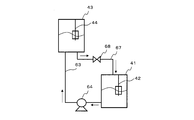
- a fuel cell system is the fuel cell system according to any one of the first to fourth aspects, wherein the first water tank is disposed above the second water tank in the direction of gravity, and the first water movement mechanism Has a first connection path for connecting the first water tank and the second water tank, and a first valve provided on the first connection path.
- a fuel cell system is the fuel cell system according to any one of the first to fourth aspects, wherein the first water movement mechanism includes a second connection path connecting the first water tank and the second water tank; A first pump provided on the second connection path for moving water from the first water tank to the second water tank.
- a fuel cell system is the fuel cell system according to the fifth aspect, further comprising a second water movement mechanism that moves the water in the second water tank to the first water tank.
- a third connection path connecting the 1 water tank and the second water tank; and a second pump provided on the third connection path for moving water from the second water tank to the first water tank.
- the controller uses the second water movement mechanism to move water from the second water tank to the first water tank before moving the water from the first water tank to the second water tank using the first water movement mechanism. Control to move.
- a valve when a valve is used as the first water moving mechanism, as a preparatory operation before performing at least one of an abnormality determination determination operation, an abnormal signal transmission, and an operation stop when a valve is used.
- the water can be moved from the second water tank to the first water tank.
- a fuel cell system is the fuel cell system according to the sixth aspect, further comprising a second water movement mechanism for moving the water in the second water tank to the first water tank, wherein the second water tank is the first water tank.
- the second water movement mechanism is disposed above the water tank in the direction of gravity, and includes a fourth connection path connecting the first water tank and the second water tank, and a second valve provided on the fourth connection path. Before the controller moves water from the first water tank to the second water tank using the first water transfer mechanism. Control to move water to the water tank.
- a pump when used as the first water transfer mechanism, as a preparatory operation before performing at least one of the determination operation for determining an abnormality, the transmission of an abnormality signal, and the shutdown of the abnormality.
- the water can be moved from the second water tank to the first water tank.
- a fuel cell system is the fuel cell system according to any one of the first to eighth aspects, further comprising a water discharge mechanism that discharges water from the second water tank, and the control unit includes the first water transfer mechanism. Before the water is transferred from the first water tank to the second water tank using the water, the water discharge mechanism is used to control the discharge of the water in the second water tank.
- the water in the second water tank can be discharged as a preparatory operation before performing at least one of an abnormality determination operation, an abnormal signal transmission, and an operation stop.
- the water discharge mechanism can use a valve or a pump.
- a fuel cell system is the fuel cell system according to any one of the first to ninth aspects, wherein the fuel cell unit generates a fuel gas containing hydrogen using a raw material and water, and a fuel A fuel cell that generates power using a gas and an oxidant gas; and a combustor that heats a hydrogen generator by burning at least one of a raw material, a fuel gas, and an anode exhaust gas discharged from the fuel cell.
- the condensed water is water obtained by condensing moisture in at least one of the anode exhaust gas, the cathode exhaust gas discharged from the fuel cell, and the combustion exhaust gas discharged from the combustor.
- the fuel cell system according to an eleventh aspect of the present invention is the fuel cell system according to the first aspect, wherein the abnormality processing operation is the transmission of an abnormal signal, and when the abnormal signal is transmitted, the abnormality notification device that notifies the abnormality.
- the operating method of the fuel cell system of the twelfth aspect of the invention recovers condensed water in which moisture in the gas discharged from the fuel cell unit is condensed, cooling water for cooling the fuel cell, and heat from the fuel cell. Detecting the amount of water in a first water tank that stores at least one of hot water for storage with a first water sensor, and second water tank storing at least one of condensed water, cooling water, and hot water.
- the case abnormal determination operation, transmission of the abnormality signal, and comprises a step of performing at least one of the abnormality processing operation of the shutdown, the.
- the operating method of the fuel cell system of the thirteenth aspect of the invention is the operating method of the fuel cell system of the twelfth aspect of the invention, which is detected by the first water amount sensor.
- the operation method of the fuel cell system of the fourteenth invention is the operation method of the fuel cell system of the twelfth invention, wherein the abnormal processing operation is operation stop, and the step of operation stop is prohibited after the operation stop. Or it restarts.
- the operating method of the fuel cell system of the fifteenth aspect of the invention is the operating method of the fuel cell system of the twelfth aspect of the invention, wherein the abnormality processing operation is a determining operation, When the amount of water to be detected does not decrease and the amount of water detected by the second water amount sensor increases, the step of determining that the first water amount sensor is abnormal, the amount of water detected by the first water amount sensor decreases, and 2 When the amount of water detected by the water amount sensor does not increase, the step of determining that the second water amount sensor is abnormal, the amount of water detected by the first water amount sensor does not decrease, and the amount of water detected by the second water amount sensor Determining that there is an abnormality in the first water movement mechanism when the increase has not increased.
- the abnormality processing operation is a determining operation
- a fuel cell system operating method is the fuel cell system operating method according to any of the twelfth to fifteenth aspects of the invention, wherein water is transferred from the first water tank to the second water tank using the first water movement mechanism.
- the step of moving the water from the second water tank to the first water tank using the second water movement mechanism for moving the water in the second water tank to the first water tank is provided before the step of moving the water.
- a pump when used as the first water transfer mechanism, as a preparatory operation before performing at least one of the determination operation for determining an abnormality, the transmission of an abnormality signal, and the shutdown of the abnormality.
- the water can be moved from the second water tank to the first water tank.
- a fuel cell system operating method is the fuel cell system operating method according to any one of the twelfth to sixteenth aspects, wherein water is transferred from the first water tank to the second water tank using the first water movement mechanism.
- the step of discharging the water of the second water tank using the water discharge mechanism for discharging the water of the second water tank is provided before the step of moving the water.
- the water in the second water tank can be discharged as a preparatory operation before performing at least one of an abnormality determination operation, an abnormal signal transmission, and an operation stop.
- the water discharge mechanism can use a valve or a pump.
- the operating method of the fuel cell system of the eighteenth invention is the operating method of the fuel cell system of the fourteenth invention, wherein the abnormality processing operation is the transmission of an abnormal signal, and when the abnormal signal is transmitted, an abnormality is indicated.
- reports is provided.
- FIG. 1 is a block diagram showing an example of a schematic configuration of the fuel cell system according to the first embodiment.
- the fuel cell system 100 of the present embodiment includes a fuel cell unit 50, a first water tank 41, a second water tank 43, a first water amount sensor 42, and a second water amount sensor 44. And a first water movement mechanism 60 and a control unit 40.
- the fuel cell unit 50 includes a fuel cell (not shown) that generates power using fuel gas and oxidant gas.
- a fuel cell for example, a polymer electrolyte fuel cell (PEFC) or a solid polymer fuel cell (SOFC) can be used.
- PEFC polymer electrolyte fuel cell
- SOFC solid polymer fuel cell
- the fuel cell unit 50 includes a hydrogen generator (not shown) that generates a fuel gas containing hydrogen using a raw material and water, and a fuel cell (not shown) that generates power using the fuel gas and an oxidant gas. And a combustor (not shown) that heats the hydrogen generator by burning at least one of the raw material, the fuel gas, and the anode exhaust gas discharged from the fuel cell.
- the condensed water described later may be water obtained by condensing moisture in at least one of the anode exhaust gas, the cathode exhaust gas discharged from the fuel cell, and the combustion exhaust gas discharged from the combustor. Good.
- the first water tank 41 collects condensed water in which moisture in the gas discharged from the fuel cell unit 50 is condensed, cooling water for cooling the fuel cell unit 50, and heat from the fuel cell unit 50. This tank stores at least one of the hot water stored in the tank.
- the second water tank 43 is a tank that accumulates at least one of condensed water, cooling water, and hot water storage.
- the 2nd water tank 43 is a tank which stores the fluid different from the fluid which the 1st water tank 41 stores among condensed water, cooling water, and hot water storage.
- the first water amount sensor 42 is a sensor that detects the amount of water in the first water tank 41.
- a float sensor, an electric conductivity meter, or the like can be used.
- the second water amount sensor 44 is a sensor that detects the amount of water in the second water tank 43.
- a float sensor, an electric conductivity meter, or the like can be used.
- the first water moving mechanism 60 moves the water in the first water tank 41 to the second water tank 43, and for example, a pump, a valve, or the like can be used.
- the control unit 40 is a control device that controls the first water movement mechanism 60.
- the control unit 40 can be configured by, for example, a microcontroller, an MPU, a PLC (Programmable Logic Controller), a logic circuit, or the like, or a storage device such as a RAM or a ROM may be added to these devices.
- the control unit 40 may be configured by a single controller that performs centralized control, or may be configured by a plurality of controllers that perform distributed control in cooperation with each other.
- the function of controlling the first water movement mechanism 60 and the function of executing an abnormality processing operation to be described later may be configured by a single controller as a whole, and correspond to individual functions.
- One controller may be provided one by one, or a single controller or a plurality of controllers may be provided for any combination of functions.
- the control unit 40 is communicably connected to the first water tank 41, the first water amount sensor 42, the second water tank 43, the second water amount sensor 44, and the first water moving mechanism 60.
- the control unit 40 controls the first water movement mechanism 60 so that the water moves from the first water tank 41 to the second water tank 43, and then the first water movement mechanism 60 compared to before the control of the first water movement mechanism 60 is started. At least when the amount of water detected by the first water amount sensor 42 does not decrease, and when the amount of water detected by the second amount-of-water sensor 44 does not increase compared to before the control of the first water movement mechanism 60 is started. In one case, an abnormality processing operation that is at least one of a determination operation for determining an abnormality, transmission of an abnormality signal, and operation stop is performed.
- the abnormality processing operation may be performed by any one of the determination operation, the transmission of the abnormality signal, and the operation stop, or may be performed simultaneously or sequentially by any two of the three operations. Alternatively, all three operations may be performed simultaneously or sequentially.
- FIG. 2 is a flowchart showing an example of the operation method of the fuel cell system according to the first embodiment.
- FIG. 2A shows a case where a determination operation is performed as an abnormal processing operation
- FIG. 2 (c) shows a case where the operation is stopped as an abnormality processing operation.
- the control unit 40 controls the first water movement mechanism 60 so that the water moves from the first water tank 41 to the second water tank 43 (step S101). .
- control unit 40 determines whether or not the detected water amount (for example, the water level) received from the first water amount sensor 42 is smaller than the detected water amount before step S101 (step S102). In order to enable such determination, the control unit 40 preferably detects and stores the amount of water in the first water tank 41 with the first water amount sensor 42 before step S101.
- the detected water amount for example, the water level
- step S ⁇ b> 102 If the determination result in step S ⁇ b> 102 is NO, the first water tank 41 has a malfunction due to a malfunction of the first water movement mechanism 60, despite the fact that water is being moved from the first water tank 41 to the second water tank 43. Although the amount of water has not decreased or the amount of water in the first water tank 41 has increased due to the movement of water from the first water tank 41 to the second water tank 43, The amount of water detected by the first water amount sensor 42 has not decreased. Therefore, it can be determined that at least one of the first water movement mechanism 60 and the first water amount sensor 42 is abnormal. Therefore, the control unit 40 executes a determination operation for determining that there is an abnormality (step S104A), and ends the operation (end). Specifically, for example, the determination operation may be to turn on an abnormality flag in a storage unit included in the control unit 40.
- step S102 determines whether or not the detected water amount (for example, the water level) received from the second water amount sensor 44 is greater than the detected water amount before step S101. (Step S103). In order to enable such determination, the control unit 40 preferably detects and stores the amount of water in the second water tank 43 with the second water amount sensor 44 before step S101.
- the detected water amount for example, the water level
- step S103 If the determination result in step S103 is YES, it is determined that there is no abnormality and the operation is ended (END). At this time, the amount of water detected by the first water amount sensor 42 has decreased, and the amount of water detected by the second water amount sensor 44 has increased, and the operation may be continued.
- step S104 determines whether the water has moved from the first water tank 41 to the second water tank 43 from the determination result in step S102. Therefore, the detected water amount of the second water amount sensor 44 is not increased. Therefore, it can be determined that the second water amount sensor 44 is abnormal. Therefore, the control unit 40 executes a determination operation for determining that there is an abnormality (step S104A), and ends the operation (end).
- the operation is ended, for example, when the operation of FIG. 2A is executed as an abnormality detection routine, the routine is ended, and the operation of the fuel cell system 100 is not necessarily stopped. Does not mean to be.
- step S102 and step S103 may be reversed (the same applies when an abnormal signal is transmitted or operation is stopped as an abnormal processing operation).
- the amount of water detected by the second water amount sensor 44 has increased, it is determined whether or not the amount of water detected by the first water amount sensor 42 has decreased.
- the determination operation step S104A is performed.
- the control unit 40 controls the first water movement mechanism 60 so that the water moves from the first water tank 41 to the second water tank 43, and then controls the first water movement mechanism 60.
- the amount of water detected by the first water amount sensor 42 does not decrease compared to before the start, and when the amount of water detected by the second water amount sensor 44 is smaller than before the control of the first water movement mechanism 60 is started.
- a determination operation for determining an abnormality is performed.
- step S104A in FIG. 2A is replaced with step S104B, and operations other than step S104B are the same as those in FIG. Therefore, description of steps common to FIG. 2A and FIG. 2B is omitted.
- step S104B the control unit 40 transmits an abnormality signal (step S104B) and ends the operation (end).
- the abnormal signal is not necessarily a signal that can be detected by the user.
- an abnormal signal may be transmitted to a monitoring facility in a remote place, or an abnormal signal may be transmitted to another device that performs an abnormal process.
- an abnormality may be notified. In this case, for example, when an abnormal signal is transmitted that is connected to the control unit 40 so as to be communicable, the abnormality is notified. An abnormality alarm may be provided.
- step S104A in FIG. 2A is replaced with step S104C, and operations other than step S104C are the same as those in FIG. Therefore, description of steps common to FIG. 2A and FIG. 2C is omitted.
- step S102 If the determination result of step S102 is NO, it can be determined that at least one of the first water movement mechanism 60 and the first water amount sensor 42 is abnormal, and the determination result of step S103 is NO, the second If it can be determined that there is an abnormality in the water amount sensor 44, the control unit 40 stops the operation of the fuel cell system 100 (step S104C) and ends the operation (END).
- the control unit 40 may perform start prohibition or restart after stopping the operation.
- the activation prohibition includes, for example, turning on the trajectory prohibition flag in the storage unit of the control unit 40, and thereafter preventing the activation even when the user presses the activation switch.
- FIG. 3 is a block diagram illustrating an example of a schematic configuration of a main part of the fuel cell system according to the first example of the first embodiment. Although omitted in FIG. 3, the fuel cell system of the first embodiment also includes a fuel cell unit 50 and a control unit 40. The elements described in FIG. 1 are denoted by the same reference numerals and names, and description thereof is omitted.
- the first water tank 41 is disposed above the first water amount sensor 42 in the gravity direction, and the first water moving mechanism 60 includes the first water tank 41 and the first water amount sensor. And a first valve 62 provided on the first connection path 61.
- the first connection path 61 is preferably provided so as to connect the drain port provided at the bottom of the first water tank 41 and the water supply port provided at the top of the second water tank 43.
- the first valve 62 may be, for example, an open / close valve or a flow rate adjustment valve that is communicably connected to the control unit 40 and is opened / closed by the control of the control unit 40.
- the first valve 62 when the first valve 62 is opened, the water in the first water tank 41 moves to the second water tank 43 by gravity.
- FIG. 4 is a table showing an outline of determination in the fuel cell system in the first example of the first embodiment.
- the state of the first valve 62 is opened, and the water moves from the first water tank 41 to the second water tank 43. Then, the amount of water detected by the first water amount sensor 42 decreases as planned, and the amount of water detected by the second water amount sensor 44 increases as planned. Therefore, it can be determined that there is no abnormality from the detection results of the first water amount sensor 42 and the second water amount sensor 44.
- state 2 after the control by controlling to open the first valve 62, the state of the first valve 62 is opened, and water is moving from the first water tank 41 to the second water tank 43.
- the amount of water detected by the first water amount sensor 42 does not decrease as planned, and the amount of water detected by the second water amount sensor 44 increases as planned. In this case, it can be determined from the detection results of the first water amount sensor 42 and the second water amount sensor 44 that the first water amount sensor 42 is abnormal.
- the state of the first valve 62 remains closed, and the water has moved from the first water tank 41 to the second water tank 43. Absent. Then, the amount of water detected by the first water amount sensor 42 does not decrease as planned, and the amount of water detected by the second water amount sensor 44 does not increase as planned. In this case, it can be determined from the detection results of the first water amount sensor 42 and the second water amount sensor 44 that the first valve 62 is abnormal.
- state 4 after the control by controlling to open the first valve 62, the state of the first valve 62 is opened, and water is moving from the first water tank 41 to the second water tank 43.
- the amount of water detected by the first water amount sensor 42 has decreased as planned, but the amount of water detected by the second water amount sensor 44 has not increased as planned. In this case, it can be determined from the detection results of the first water amount sensor 42 and the second water amount sensor 44 that the second water amount sensor 44 is abnormal.
- an abnormal signal transmission or operation stop in addition to the determination operation, an abnormal signal transmission or operation stop, or any combination of these three may be executed simultaneously or sequentially.
- a valve when used as the first water movement mechanism, it is possible to perform at least one abnormality response operation of determination operation for determining abnormality, transmission of an abnormality signal, and operation stop.
- FIG. 5 is a block diagram showing an example of a schematic configuration of a main part of the fuel cell system in the second example of the first embodiment. Although omitted in FIG. 5, the fuel cell system of the second embodiment also includes a fuel cell unit 50 and a control unit 40.
- the elements described in FIG. 1 are denoted by the same reference numerals and names, and description thereof is omitted.
- the first water movement mechanism 60 is provided on the second connection path 63 and the second connection path 63 that connect the first water tank 41 and the first water amount sensor 42, And a first pump 64 for moving water from the first water tank 41 to the second water tank 43.
- the second connection path 63 is provided so as to connect a drain port provided at the bottom of the first water tank 41 and a water supply port provided at the top of the second water tank 43.
- the first pump 64 may be, for example, a pump that is communicably connected to the control unit 40 and operates under the control of the control unit 40.
- the first pump 64 when the first pump 64 is driven, the water in the first water tank 41 moves to the second water tank 43. In such a configuration, even when the first water tank 41 is disposed below the second water tank 43 in the direction of gravity, the water is moved from the first water tank 41 to the second water tank 43 against the gravity. Can be made.
- FIG. 6 is a table showing an outline of determination in the fuel cell system in the second example of the first embodiment.
- the first pump 64 is actually operated by driving the first pump 64, and the water is moving from the first water tank 41 to the second water tank 43. Then, the amount of water detected by the first water amount sensor 42 decreases as planned, and the amount of water detected by the second water amount sensor 44 increases as planned. Therefore, it can be determined that there is no abnormality from the detection results of the first water amount sensor 42 and the second water amount sensor 44.
- the first pump 64 is actually operated by driving the first pump 64, and the water is moving from the first water tank 41 to the second water tank 43.
- the amount of water detected by the first water amount sensor 42 does not decrease as planned, and the amount of water detected by the second water amount sensor 44 increases as planned. In this case, it can be determined from the detection results of the first water amount sensor 42 and the second water amount sensor 44 that the first water amount sensor 42 is abnormal.
- the first pump 64 does not actually operate, and the water moves from the first water tank 41 to the second water tank 43. Absent. Then, the amount of water detected by the first water amount sensor 42 does not decrease as planned, and the amount of water detected by the second water amount sensor 44 does not increase as planned. In this case, it can be determined from the detection results of the first water amount sensor 42 and the second water amount sensor 44 that the first valve 62 is abnormal.
- the first pump 64 is actually operated by driving the first pump 64, and the water is moving from the first water tank 41 to the second water tank 43.
- the amount of water detected by the first water amount sensor 42 has decreased as planned, but the amount of water detected by the second water amount sensor 44 has not increased as planned. In this case, it can be determined from the detection results of the first water amount sensor 42 and the second water amount sensor 44 that the second water amount sensor 44 is abnormal.
- an abnormality signal transmission or operation stop in addition to the determination operation, an abnormality signal transmission or operation stop, or any combination of the three may be executed simultaneously or sequentially.
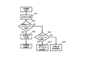
- FIG. 7 is a flowchart showing an example of an operation method of the fuel cell system in the first modification of the first embodiment.
- the abnormality processing operation is a determination operation, and the control unit 40 does not decrease the amount of water detected by the first water amount sensor 42 during the determination operation, and the second
- the control unit 40 does not decrease the amount of water detected by the first water amount sensor 42 during the determination operation, and the second
- the amount of water detected by the water amount sensor 44 increases, it is determined that the first water amount sensor 42 is abnormal, the amount of water detected by the first water amount sensor 42 decreases, and the amount of water detected by the second water amount sensor 44 increases. If not, it is determined that the second water amount sensor 44 is abnormal, the water amount detected by the first water amount sensor 42 has not decreased, and the water amount detected by the second water amount sensor 44 has not increased. It is determined that the first water movement mechanism 60 is abnormal.
- the abnormality processing operation is a determination operation
- the step of performing the determining operation is a step of determining that the first water amount sensor 42 is abnormal when the amount of water detected by the first water amount sensor 42 does not decrease and the amount of water detected by the second water amount sensor 44 increases.
- a step of determining that the first water movement mechanism 60 is abnormal when the amount of water detected by 42 does not decrease and the amount of water detected by the second water amount sensor 44 does not increase.
- the hardware configuration of the first modified example can be the same as that of the first embodiment and the examples and modified examples thereof, and detailed description thereof is omitted.
- the control unit 40 controls the first water movement mechanism 60 so that the water moves from the first water tank 41 to the second water tank 43 (step S201). .
- control unit 40 determines whether or not the detected water amount (for example, the water level) received from the first water amount sensor 42 is smaller than the detected water amount before step S201 (step S202). In order to enable such determination, it is preferable that the control unit 40 stores the detected water amount received from the first water amount sensor 42 before step S201.
- the detected water amount for example, the water level
- step S202 determines whether or not the detected water amount (for example, the water level) received from the second water amount sensor 44 is greater than the detected water amount before step S201. (Step S203).
- the detected water amount for example, the water level
- step S203 determines that there is no abnormality and ends the operation (end), for example, as shown in state 1 after control in FIG. 4 or FIG.
- step S203 determines that there is an abnormality in the second water amount sensor 44, for example, as shown in FIG. 4 or 6 as the state 4 after control (step S204). A flag to that effect is set and the operation ends (END).
- step S202 determines whether or not the detected water amount (for example, the water level) received from the second water amount sensor 44 is greater than the detected water amount before step S201. (Step S205).
- the detected water amount for example, the water level
- step S205 determines that there is an abnormality in the first water amount sensor 42, for example, as shown in FIG. 4 or FIG. 6 as the state 2 after control (step S206). A flag to that effect is set and the operation ends (END).
- step S206 determines that there is an abnormality in the first water moving mechanism 60, for example, as shown in FIG. 4 or 6 as the state 3 after control (step S206). A flag to that effect is set and the operation ends (END).
- the determination operation is performed.
- transmission of an abnormal signal and / or operation stop may be performed simultaneously or sequentially.
- FIG. 8 is a block diagram illustrating an example of a schematic configuration of a fuel cell system according to a second modification of the first embodiment.
- the fuel cell system of the second modification is the fuel cell system of the first embodiment, and includes a second water movement mechanism that moves the water in the second water tank 43 to the first water tank 41, and the second water movement mechanism is A third connection path 65 for connecting the first water tank 41 and the second water tank 43, and a third connection path 65 provided on the third connection path 65 for moving water from the second water tank 43 to the first water tank 41.
- the control unit 40 supplies water from the first water tank 41 to the second water tank 43 using the first water movement mechanism 60 (the first connection path 61 and the first valve 62). Before moving, control is performed to move water from the second water tank 43 to the first water tank 41 using the second water movement mechanism (the third connection path 65, the second pump 66).
- the operation method of the fuel cell system according to the second modification is the same as the operation method of the fuel cell system according to the first embodiment, in which water is transferred from the first water tank 41 to the second water tank 43 using the first water movement mechanism 60.
- the second water tank 43 is moved from the second water tank 43 using the second water movement mechanism (the third connection path 65, the second pump 66) that moves the water in the second water tank 43 to the first water tank 41.
- the step of moving water to the 1 water tank 41 is provided.
- the third connection path 65 is preferably provided so as to connect the drain port provided at the bottom of the second water tank 43 and the water supply port provided at the top of the first water tank 41.
- the second pump 66 may be, for example, a pump that is communicably connected to the control unit 40 and operates under the control of the control unit 40.
- the water in the second water tank 43 moves to the first water tank 41 by driving the second pump 66.
- the water is moved from the second water tank 43 to the first water tank 41 against the gravity. Can be made.
- a valve when used as the first water movement mechanism, a preparatory operation before performing at least one of an abnormality determination operation, an abnormal signal transmission, and an operation stop in response to an abnormality is determined.
- water can be moved from the second water tank to the first water tank.
- FIG. 9 is a block diagram illustrating an example of a schematic configuration of a fuel cell system according to a third modification of the first embodiment.
- the fuel cell system of the third modification is the fuel cell system of the second embodiment, and includes a second water movement mechanism that moves the water of the second water tank 43 to the first water tank 41.
- the second water tank 43 The second water movement mechanism is disposed above the first water tank 41 in the gravitational direction, and the second water movement mechanism is connected to the fourth connection path 67 connecting the first water tank 41 and the second water tank 43, and on the fourth connection path 67.
- the control unit 40 uses the first water movement mechanism 60 (the second connection path 63 and the first pump 64) to move from the first water tank 41 to the second water tank.
- the second water moving mechanism (the fourth connection path 67, the second valve 68) is used to control the water to move from the second water tank 43 to the first water tank 41.
- the operation method of the fuel cell system according to the third modification is the same as the operation method of the fuel cell system according to the second embodiment, in which water is transferred from the first water tank 41 to the second water tank 43 using the first water movement mechanism 60.
- the second water tank 43 is moved from the second water tank 43 using the second water movement mechanism (the fourth connection path 67, the second valve 68) that moves the water in the second water tank 43 to the first water tank 41.
- the step of moving water to the 1 water tank 41 is provided.
- connection path 67 is provided so as to connect a drain port provided at the bottom of the second water tank 43 and a water supply port provided at the top of the first water tank 41.
- the second valve 68 may be, for example, an on-off valve or a flow rate adjustment valve that is communicably connected to the control unit 40 and is opened and closed by the control of the control unit 40.
- the second valve 68 when the second valve 68 is opened, the water inside the second water tank 43 moves to the first water tank 41 due to gravity.
- a pump when used as the first water transfer mechanism, a preparatory operation before performing at least one of an abnormality determination operation, an abnormality signal transmission, and an operation stop in response to an abnormality is determined.
- water can be moved from the second water tank to the first water tank.
- FIG. 10 is a block diagram illustrating an example of a schematic configuration of a fuel cell system according to a fourth modification of the first embodiment.
- the fuel cell system 100A of the fourth modified example has a water discharge mechanism 69 for discharging water from the second water tank in the fuel cell system of the first embodiment, and the control unit 40 uses the water discharge mechanism to Before moving the water from the first water tank 41 to the second water tank 43, the water discharge mechanism 69 is used to control the discharge of the water in the second water tank 43.
- the operation method of the fuel cell system according to the fourth modification is the same as the operation method of the fuel cell system according to any of the above-described embodiments or modifications, in which water is transferred from the first water tank 41 to the second water tank 43 using the first water movement mechanism 60.
- the step of discharging the water of the second water tank 43 using the water discharge mechanism 69 for discharging the water of the second water tank 43 is provided before the step of moving the water.
- the fuel cell system 100A may include water storage means other than the first water tank 41 and the second water tank 43, and the water discharge mechanism 69 may discharge water to the water storage means. However, it is preferable that the water discharge mechanism 69 discharges the water in the second water tank 43 to the outside of the fuel cell system 100A.
- the water discharge mechanism 69 starts with, for example, a drain opening provided at the lower portion of the second water tank 43 and opens to the outside of the fuel cell system 100A, and a valve (open / close valve) provided in the flow path. , A flow regulating valve, etc.) or a pump.
- the water discharge mechanism 69 is connected to the control unit 40 so as to be communicable, for example, and discharges the water in the second water tank 43 to the outside of the second water tank 43 based on the control of the control unit 40.
- This modification may be combined with the first and second embodiments and the first to third modifications.
- the water in the second water tank is used as the second water tank. , More preferably outside the fuel cell system.
- FIG. 11 is a block diagram illustrating an example of a schematic configuration of a fuel cell system according to the second embodiment.
- the fuel cell power generation device 1 (fuel cell system) includes hydrogen from a cell stack 2 (fuel cell) that generates power using an oxidant gas containing fuel gas and at least oxygen, and raw material and water.
- a hydrogen generator 3 that generates fuel gas
- a condensed water tank 4 that accumulates water that has condensed through the air that has passed through the cell stack and the air discharged from the fuel generator, and the amount of water in the condensed water tank 4 is detected.
- a cooling water supply pump 10 as condensed water discharge means for discharging water from the condensed water tank 4
- the control unit 36 is provided.
- the cell stack 2 is supplied with air as an oxidant gas containing at least oxygen from the outside of the fuel cell power generator 1 through the cathode air pipe 14.
- the cathode air consumes part or all of the oxygen in the cathode air during power generation in the cell stack 2, and the remaining exhaust cathode air is guided to the exhaust cathode air heat exchanger 17 through the exhaust cathode air pipe 16. Since the exhaust cathode air contains a large amount of moisture, when the exhaust cathode air heat exchanger 17 removes heat and the temperature is lowered, the moisture is condensed and water is generated.
- the condensed water and the exhaust cathode air are guided to the condensed water tank 4 (cathode condensed water tank).
- the condensed water accumulates in the condensed water tank 4, and the gas component passes through the gas-liquid contact portion 21 provided in the condensed water tank 4 and is then discharged to the outside of the fuel cell power generator 1 through the cathode exhaust pipe 22.
- a substance having water in the molecule such as hydrocarbon is introduced from the outside of the fuel cell power generator 1 to the reforming section 3a of the hydrogen generator 3 through the raw material pipe 12 as a raw material.
- Raw materials include methane, ethane, In addition to propane and other gaseous hydrocarbons, kerosene and petroleum liquid hydrocarbons such as kerosene and petroleum can be used.
- city gas 13A is used as a raw material.
- a fuel gas containing hydrogen is generated by a reaction from the supplied raw material and water.
- the fuel produced by the hydrogen generator 3 is carried to the cell stack 2 by the fuel gas pipe 15.
- the cell stack 2 electric energy, thermal energy, and water are generated by hydrogen in the fuel and oxygen in the oxidant gas.
- the off gas after a part of hydrogen in the fuel gas is used in the cell stack 2 is guided to the AD heat exchanger 25 through the off gas pipe 23. Since the AD heat exchanger 25 takes heat from the off gas, the temperature of the off gas decreases, and the moisture contained in the off gas is condensed into water.
- the off gas containing condensed water is guided to the AD tank 6 (anode condensed water tank).
- Condensed water is stored in the AD tank 6, and off-gas is led to the burner unit 3 b in the hydrogen generator 3 through the AD pipe 24.
- the air taken into the fuel cell power generator 1 directly from the outside of the fuel cell power generator 1 or the air taken from the inside of the fuel cell power generator 1 and the off-gas are mixed by the combustion air pipe 13.
- Burn. Part of the heat generated during combustion is used as reaction heat for generating hydrogen from the raw material and water.
- Combustion exhaust gas containing heat not used as reaction heat is guided to the combustion exhaust gas heat exchanger 27 through the combustion exhaust gas pipe 26. In the combustion exhaust gas heat exchanger 27, heat is taken from the combustion exhaust gas, the temperature is lowered, and moisture is condensed.
- the combustion exhaust gas after the moisture is condensed is guided to the outside of the fuel cell power generator 1 by the combustion exhaust gas exhaust pipe 37.
- the water condensed from the combustion exhaust gas is guided to the gas-liquid contact portion 21 provided in the condensed water tank 4.
- Condensed water from the combustion exhaust gas has an acidic pH because carbon dioxide generated during combustion is contained in the combustion exhaust gas.
- the gas-liquid contact part 21 comes into contact with the exhaust cathode air in a facing manner.
- the carbon dioxide contained in the combustion exhaust gas moves to the exhaust cathode air having a low carbon dioxide concentration, so that the concentration of carbon dioxide in the condensed water from the combustion exhaust gas is lowered, the pH is raised, and it goes to neutrality. .
- the condensed water tank 4 is provided with a condensed water tank float sensor 5 as a condensed water amount sensor.
- a cooling water supply pump 10 is connected as a condensed water discharge means.
- the cooling water supply pump 10 carries water out of the condensed water tank 4 by a signal from the control unit 36.
- the water carried out from the condensed water tank 4 passes through a water purification unit that removes particles, ions, or bacilli contained in the water, and then is supplied to the cooling water tank 28 through a cooling water supply pipe 38.
- the cooling water supply means may be provided separately from the condensed water discharge means, in this embodiment, the cooling water supply pump 10 is used not only as the condensed water discharge means but also as the cooling water supply means.
- the cooling water tank 28 is provided with a cooling water tank float sensor 29 as a cooling water quantity sensor.
- the cooling water pumped out from the cooling water tank 28 by the cooling water circulation pump 30 is sent to the cooling water heat exchanger 31 from the cooling water tank 28. Since heat is taken away in the cooling water heat exchanger, the temperature of the cooling water becomes an appropriate temperature.
- the temperature of the cooling water is appropriately controlled by controlling the amount of hot water stored in the cooling water heat exchanger so that the heat moves so that the temperature becomes appropriate. Cooling water having an appropriate temperature is caused to flow into the cell stack 2. Since the cell stack 2 also generates heat during power generation, the temperature of the cell stack is appropriately controlled by flowing cooling water having an appropriate water temperature with an appropriate amount of water.
- a path for guiding water to the reforming water pump 32 is formed from a path through which the cooling water circulates between the cooling water tank 28 and the cell stack 2.
- the reforming water pump 32 guides the cooling water to the hydrogen generator 3 through the reforming water valve 33.
- the path connected to the AD tank 6 via the AD valve 34 is also configured in the discharge path of the reformed water pump 32.
- the cooling water discharge means and the AD tank water supply means may be provided independently, but in the present embodiment, the reforming water pump 32 is also used as the cooling water discharge means and the AD water supply means. Thereby, since a different role can be performed with a small number of parts, a highly reliable fuel cell power generator can be realized.
- the AD tank 6 is disposed above the condensed water tank 4, and water in the AD tank 6 is guided to the condensed water tank 4 by an AD pipe 9 provided with an AD closing valve 8.
- the AD stop valve is not only a condensed water supply means but also an AD water discharge means.
- the AD tank 6 stores condensed water from off-gas, but the fuel gas made from the raw material contains carbon dioxide in addition to hydrogen, so the condensed water from off-gas is generated by carbon dioxide.
- the water has a low pH. While being guided from the AD tank 6 to the condensed water tank 4, it passes through the gas-liquid contact portion 21. At this time, carbon dioxide in the condensed water moves and is removed by contact with the exhaust cathode air, so that the concentration of carbon dioxide in the condensed water is reduced and the pH becomes near neutral and is stored in the condensed water tank 4. It is. When the amount of supplied water is larger than the amount of water discharged from the condensed water tank 4, it is discharged from the condensed water drain pipe 39 to the outside of the fuel cell power generator 1.
- the direct current power generated in the cell stack 2 is sent to the power circuit unit 35 and converted into alternating current or direct current having a desired voltage to be used. It is sent to the outside of the power generator 1 and used.
- water is supplied from the outside of the fuel cell power generator 1 from the pipe 18 containing hot water, passes through the AD heat exchanger 25, and then the exhaust cathode air heat exchanger. 17 or the combustion exhaust gas heat exchanger 27, and the temperature rises every time it passes through the cooling water heat exchanger 31, and becomes hot hot water and is led to the outside of the fuel cell power generator 1 by the hot water storage discharge pipe. Used for hot water supply.
- FIG. 12 is a flowchart illustrating an example of an operation method of the initial operation process 1 in the second embodiment.
- the condensed water tank float sensor 5 should indicate a small amount of water (step S301).
- the control unit 36 can determine that the condensed water tank float sensor 5 has failed, and determines the failure (step S302).
- the water supply valve 20 is opened by the control part 36, and water is supplied to the condensed water tank 4 from the outside (step S303).
- the control unit 36 determines that both the water supply valve 20 and the condensed water tank float sensor 5 are normal. (Step S305), the process moves to the initial operation step 2.
- step S304 If the condensate tank float sensor 5 does not indicate a large amount of water even after the time (G2 / KYV) has elapsed (NO in step S304), either the water supply valve 20 or the condensate tank float sensor 5 is Judge that it is broken. In this case, the cooling water supply pump 10 is operated (step S306). Since the cooling water tank 28 does not contain water in the initial stage, the cooling water tank float sensor 29 indicates a small amount of water.
- step S307 When the cooling water supply pump 10 is operated and the cooling water tank float sensor 29 indicates a large amount of water (YES in step S307), the water supply valve 20 is normal because there is water in the condensed water tank 4, and the condensed water It can be determined that the tank float sensor 5 has failed (step S308). Even if the cooling water supply pump 10 is operated, if the cooling water tank float sensor 29 does not indicate a large amount of water (after a predetermined time has elapsed), it can be determined that the water supply valve 20 has failed (step S309). As a result, by stopping operation such as power generation or notifying a failure, it is possible to prompt a quick failure response without damaging other components, and a highly reliable fuel cell power generator can be realized. is there.
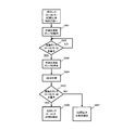
- FIG. 13 is a flowchart illustrating an example of the operation method of the initial operation step 2 in the second embodiment.
- the cooling water supply pump 10 is operated to put water into the cooling water tank 28 (step S401).
- the design water amount stored until the coolant tank float sensor 29 provided in the coolant tank 28 indicates a large amount of water is R2 liters
- the design flow rate of the water supplied from the coolant supply pump 10 is RKV liters per minute.
- the coolant tank float sensor 29 should indicate a large amount of water in (R2 / RKV) minutes.
- step S402 If the cooling water float sensor 29 indicates a large amount of water in (R2 / RKV) (YES in step S402), the cooling water tank can safely supply water if the cooling water tank float sensor 29 indicates a large amount of water. Since it can be determined that both the float sensor 29 and the cooling water supply pump 10 are normal (step S403), the process moves to the initial operation step 3. If the cooling water tank float sensor 29 does not indicate a large amount of water even if the time has passed (R2 / RKV) minutes (NO in step S402), either the cooling water tank float sensor 29 or the cooling water supply pump 10 is used. It is determined that one of them has failed.
- step S404 if the condensate tank float sensor 5 indicates that the amount of water is small (YES in step S404), it indicates that the water has been carried out from the condensate tank 4, and therefore it can be determined that the cooling water supply pump 10 is normal. Then, it is determined that the cooling water tank float sensor 29 is out of order (step S405). Conversely, if the condensed water tank float sensor 5 does not indicate a small amount of water (NO in step S404), it indicates that no water is being carried out from the condensed water tank 4, so that the cooling water supply pump 10 has failed. Confirm (step S406). By stopping the operation such as power generation or notifying a failure, it is possible to prompt a quick failure response without damaging other components, and to realize a highly reliable fuel cell power generator.
- FIG. 14 is a flowchart illustrating an example of an operation method of the initial operation process 3 in the second embodiment.
- step S503 When the AD tank float sensor 7 indicates a large amount of water for (AD2 / KPV) (YES in step S503), it can be determined that both the AD tank float sensor 7 and the reforming water pump 32 are normal (step S504). Therefore, it moves to the initial operation process 4. If the AD tank float sensor 7 does not indicate a large amount of water even after the time (AD2 / KPV) has elapsed (NO in step S503), the AD valve 34 is a valve at the discharge pressure of the reforming water pump 32.
- step S506 Since the spring pressure and direction of the valve are adjusted so that the valve opens, if the reforming water pump 32 is normal even if it fails, water will flow, so either the AD tank float sensor 7 or the reforming water pump 32 It is determined that one of them is out of order. In this case, if the cooling water tank float sensor 29 indicates a small amount of water (YES in step S505), it indicates that the water has been carried out from the cooling water tank 28. Therefore, it can be determined that the reforming water pump 32 is normal. It is determined that the AD tank float sensor 7 has failed (step S506).
- step S507 if the cooling water tank float sensor 29 does not indicate a small amount of water, it indicates that the water is not carried out from the cooling water tank 28, so that it is determined that the reforming water pump 32 has failed. .
- the cooling water tank float sensor 29 By stopping the operation such as power generation or notifying a failure, it is possible to prompt a quick failure response without damaging other components, and to realize a highly reliable fuel cell power generator.
- FIG. 15 is a flowchart illustrating an example of the operation method of the initial operation step 4 in the second embodiment.
- the AD stop valve 8 is opened (step S601), and water is poured into the condensed water tank 4 from the AD pipe 9. If the design flow rate of the water supplied from the AD pipe 9 is AHV liters per minute before the condensed water tank float sensor 5 indicates a large amount of water, the condensed water tank float sensor 5 is within (AD2 / AHV) minutes. Should show a large amount of water.
- step S602 If the condensed water tank float sensor 5 indicates a large amount of water for (AD2 / AHV) (YES in step S602), it can be determined that the AD stop valve is normal (step S603), and the initial operation process is terminated. If the condensed water tank float sensor 5 does not show a large amount of water even after the time (AD2 / AHV) has elapsed (NO in step S602), either the condensed water tank float sensor 5 or the AD shutoff valve 8 is used. Is determined to be malfunctioning.
- step S604 if the AD tank float sensor 7 indicates that the amount of water is small (YES in step S604), it indicates that the water has been carried out from the AD tank 6, so it can be determined that the AD stop valve 8 is normal. It is determined that the tank float sensor 5 is out of order (step S605). Conversely, if the AD tank float sensor 7 does not indicate a small amount of water (NO in step S604), it indicates that no water has been carried out from the AD tank 6, so it is determined that the AD shutoff valve 8 has failed ( Step S606).
- the condensed water tank float sensor 5 since it is confirmed that there is no failure in the condensed water tank float sensor 5 in the initial operation step 1, the condensed water tank float sensor 5 does not indicate a large amount of water even if the time has elapsed after (AD2 / AHV) minutes. In this case, it may be immediately determined that the AD shutoff valve 8 has failed. Thus, by stopping the operation of power generation or notifying a failure, it is possible to prompt a quick failure response without damaging other components, and to realize a highly reliable fuel cell power generator. .
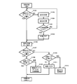
- FIG. 16 is a flowchart illustrating an example of the operation method of the cooling water / AD water draining step in the second embodiment.
- the AD valve 34 is opened (step S701), the reforming water pump 32 is operated (step S702), and the AD closing valve 8 is opened (step S703).
- the water in the cooling water tank 28 flows into the AD tank 6, and the water in the AD tank flows into the condensed water tank 4.
- the cooling water tank float sensor 29 should indicate a small amount of water.
- step S704 If the cooling water tank float sensor 29 indicates a small amount of water within a certain time (YES in step S704), the reforming water pump 32 is stopped (step S705), and the AD valve 34 is closed (step S706). If the cooling water tank float sensor 29 does not indicate a small amount of water within a certain time (NO in step S704 and YES in step S707), the control unit 36 sets the water drain failure flag 1 (step S708), and the reforming water pump 32 is stopped (step S705), and the AD valve 34 is closed (step S706). If the AD tank float sensor 7 indicates a small amount of water within a certain time (step S705), the AD stop valve 8 is closed.
- step S711 If the AD tank float sensor 7 does not indicate a small amount of water within a certain time (NO in step S709 and YES in step S710), the control unit 36 sets the water drain failure flag 2 (step S711), and sets the AD close valve 8 Close (step S712). If there is no failure flag ("None" in step S713), it is determined that the cooling water / AD water draining process has been completed normally, and the routine proceeds to the periodic inspection process 1. In the case of the drainage failure flag 1 (“1” in step S713), the process proceeds to the cooling water tank float sensor reforming water pump discrimination process. In the case of the drainage failure flag 2 (“2” in step S713), the AD tank float It moves to the sensor AD closing valve discrimination process.
- FIG. 17 is a flowchart showing an example of an operation method of a cooling water tank float sensor reforming water pump discrimination step in the second embodiment.
- the AD valve 34 is opened (step S801), and the reforming water pump 32 is operated (step S802).
- the AD tank float sensor 7 indicates a large amount of water within a certain time (YES in step S803), water is being sent out from the cooling water tank 28, so the cooling water tank float sensor 29 has failed. Is determined (step S804).
- step S803 If the AD tank float sensor 7 does not indicate a large amount of water within a certain time (NO in step S803), it is because water has not been sent, so it is determined that the reforming water pump 32 has failed (step S805). ). Thus, by stopping the operation of power generation or notifying a failure, it is possible to prompt a quick failure response without damaging other components, and to realize a highly reliable fuel cell power generator. .
- FIG. 18 is a flowchart illustrating an example of an operation method of the AD tank float sensor AD closing valve determination step according to the second embodiment.
- the cooling water supply pump 10 is operated until the condensed water tank float sensor 5 indicates a small amount of water (steps S901 to S902).
- the cooling water supply pump 10 is stopped (step S903).
- the AD valve 34 is opened (step S904).
- step S905 If the condensed water tank float sensor 5 indicates a large amount of water within a certain time (YES in step S905), water is being sent out from the AD tank 6, so that the AD tank It is determined that the float sensor 7 is out of order (step S906). If the condensate tank float sensor 5 does not indicate a large amount of water within a certain time (NO in step S905), it is because water has not been sent, so it is determined that the AD shutoff valve 8 has failed (step S907). ). Thus, by stopping the operation of power generation or notifying a failure, it is possible to prompt a quick failure response without damaging other components, and to realize a highly reliable fuel cell power generator. .
- FIG. 19 is a flowchart illustrating an example of an operation method of the periodic inspection step 1 in the second embodiment.
- the cooling water supply pump 10 is operated (step S1002).
- the water supply valve 20 is opened and closed (steps S1003 to S1004), and water is supplied to the condensed water tank 4. If the condensed water tank float sensor 5 indicates a large amount of water within a certain time, the cooling water supply pump 10 is operated to move to the step (step S1002).
- step S1005 If the condensate tank float sensor 5 does not indicate a large amount of water within a certain time (YES in step S1005), the controller 36 records the failure flag 3 (step S1006), and operates the cooling water supply pump 10 (step ( Move to step S1002). If the cooling water tank float sensor 29 indicates a large amount of water within a certain time (YES in step S1007), and there is no failure flag 3 ("NO" in step S1008), it is determined that there is no problem in the periodic inspection process 1, and Move to inspection process 2. If there is a failure flag 3 (“Yes” in step S1008), the condensed water tank float sensor 5 has failed, so it is determined that there is a failure (step S1009).
- step S1007 If the cooling water tank float sensor 29 does not indicate a large amount of water within a certain time (NO in step S1007) and there is no failure flag 3 ("NO" in step S1010), the failure flag 4 is set by the control unit 36. It records (step S1011) and moves to the periodic inspection process 2. If there is a failure flag 3 (“Yes” in step S1010), it is determined that the water supply valve 20 is in failure (step S1012). Thus, by stopping the operation of power generation or notifying a failure, it is possible to prompt a quick failure response without damaging other components, and to realize a highly reliable fuel cell power generator. .
- FIG. 20 is a flowchart illustrating an example of an operation method of the periodic inspection step 2 in the second embodiment.
- the AD valve 34 is opened (step S1101), and the reforming water pump 32 is operated (step S1102).
- the AD tank float sensor 7 indicates a large amount of water (YES in step S1103).
- the failure flag 4 is not present (“NO” in step S1104), it is determined that there is no problem in the periodic inspection process 2, and the periodic inspection process 3 Move to. If there is a failure flag 4 ("Yes" in step S1104), the cooling water tank float sensor 29 has failed, so it is determined that there is a failure (step S1105).
- Step S1107 If the AD tank float sensor 7 does not indicate a large amount of water within a certain time (NO in step S1103) and there is no failure flag 4 ("NO" in step S1106), the failure flag 5 is recorded by the control unit 36. (Step S1107), the process moves to the periodic inspection process 3. If there is the failure flag 4 (“Yes” in step S1106), it is determined that the reforming water pump 32 has failed (step S1108). Thus, by stopping the operation of power generation or notifying a failure, it is possible to prompt a quick failure response without damaging other components, and to realize a highly reliable fuel cell power generator. .
- FIG. 21 is a flowchart illustrating an example of an operation method of the periodic inspection step 3 in the second embodiment.
- the cooling water supply pump 10 is operated (step S1202) so that the condensed water tank float sensor 5 indicates a low water amount. If the condensed water tank float sensor 5 does not indicate a large amount of water even after a certain time (“Yes” in step S1203), it is determined that the condensed water tank float sensor 5 has failed (step S1204).
- step S1205 After the condensed water tank float sensor 5 indicates that the amount of water is low, the AD stop valve 8 is opened (step S1205), the condensed water tank float sensor 5 indicates that the amount of water is large (YES in step S1206), and there is no failure flag 5 (No in step S1207), it is determined that everything is normal, and the periodic inspection is terminated. If there is a failure flag 5 ("Yes" in step S1207), it is determined that the AD tank float sensor 7 has failed, so the AD tank float sensor 7 is determined to have failed (step S1208).
- step S1206 If the condensed water tank float sensor 5 does not indicate a large amount of water (NO in step S1206), if there is a failure flag 5 ("Yes" in step S1209), it is determined that the reforming water pump has failed (step S1210). If the failure flag 5 is not present, it is determined that the AD stop valve has failed (step S1211).
- the fuel cell system according to the present invention is useful because it can grasp an abnormality more reliably with a simpler configuration.
Landscapes
- Life Sciences & Earth Sciences (AREA)
- Engineering & Computer Science (AREA)
- Manufacturing & Machinery (AREA)
- Sustainable Development (AREA)
- Sustainable Energy (AREA)
- Chemical & Material Sciences (AREA)
- Chemical Kinetics & Catalysis (AREA)
- Electrochemistry (AREA)
- General Chemical & Material Sciences (AREA)
- Fuel Cell (AREA)
Abstract
L'invention concerne un système de pile à combustible qui comprend : une unité de pile à combustible (50) ; un premier réservoir d'eau (41) qui stocke de l'eau condensée, de l'eau de refroidissement et/ou de l'eau chaude en réserve ; un second réservoir d'eau (43) qui stocke de l'eau condensée, de l'eau de refroidissement et/ou de l'eau chaude en réserve ; un premier détecteur de volume d'eau (42) qui détecte le volume d'eau dans le premier réservoir d'eau ; un second détecteur de volume d'eau (44) qui détecte le volume d'eau dans le second réservoir d'eau ; un premier mécanisme de transfert d'eau (60) qui transfère de l'eau dans le premier réservoir d'eau à partir du second réservoir d'eau ; et une unité de commande (40) qui commande le premier mécanisme de transfert d'eau. L'unité de commande commande le premier mécanisme de transfert d'eau et, si le volume d'eau détecté par le premier détecteur de volume d'eau n'a pas diminué par comparaison avec l'état antérieur à la commande du premier mécanisme de transfert d'eau et/ou si le volume d'eau détecté par le second détecteur de volume d'eau n'a pas augmenté par comparaison avec l'état antérieur à la commande du premier mécanisme de transfert d'eau, le système de pile à combustible prend des mesures de traitement de l'erreur, qui sont soit une action d'évaluation qui évalue l'existence de l'erreur, soit l'émission d'un signal d'erreur, soit l'arrêt du fonctionnement.
Priority Applications (3)
| Application Number | Priority Date | Filing Date | Title |
|---|---|---|---|
| EP11750379.7A EP2544286B1 (fr) | 2010-03-04 | 2011-03-02 | Système de pile à combustible et procédé de fonctionnement de celui-ci |
| JP2012503017A JP5323981B2 (ja) | 2010-03-04 | 2011-03-02 | 燃料電池システムおよびその運転方法 |
| US13/582,668 US20120328964A1 (en) | 2010-03-04 | 2011-03-02 | Fuel cell system and method of operating thereof |
Applications Claiming Priority (2)
| Application Number | Priority Date | Filing Date | Title |
|---|---|---|---|
| JP2010-047450 | 2010-03-04 | ||
| JP2010047450 | 2010-03-04 |
Publications (1)
| Publication Number | Publication Date |
|---|---|
| WO2011108266A1 true WO2011108266A1 (fr) | 2011-09-09 |
Family
ID=44541936
Family Applications (1)
| Application Number | Title | Priority Date | Filing Date |
|---|---|---|---|
| PCT/JP2011/001224 Ceased WO2011108266A1 (fr) | 2010-03-04 | 2011-03-02 | Système de pile à combustible et procédé de fonctionnement de celui-ci |
Country Status (4)
| Country | Link |
|---|---|
| US (1) | US20120328964A1 (fr) |
| EP (1) | EP2544286B1 (fr) |
| JP (1) | JP5323981B2 (fr) |
| WO (1) | WO2011108266A1 (fr) |
Cited By (4)
| Publication number | Priority date | Publication date | Assignee | Title |
|---|---|---|---|---|
| JP2019160561A (ja) * | 2018-03-13 | 2019-09-19 | 大阪瓦斯株式会社 | 燃料電池システム |
| JP2020017507A (ja) * | 2018-07-27 | 2020-01-30 | 京セラ株式会社 | 燃料電池装置、制御装置および制御プログラム |
| JP2020194666A (ja) * | 2019-05-27 | 2020-12-03 | ダイニチ工業株式会社 | 燃料電池装置 |
| JP2020202009A (ja) * | 2019-06-05 | 2020-12-17 | ダイニチ工業株式会社 | 燃料電池装置 |
Families Citing this family (3)
| Publication number | Priority date | Publication date | Assignee | Title |
|---|---|---|---|---|
| KR102767147B1 (ko) * | 2019-07-22 | 2025-02-11 | 주식회사 엘지에너지솔루션 | 전력 저장 장치 |
| KR20230132300A (ko) * | 2022-03-08 | 2023-09-15 | 현대자동차주식회사 | 연료전지 냉각시스템 |
| EP4279385B1 (fr) * | 2022-05-20 | 2025-02-26 | Airbus Operations GmbH | Système de réservoir de détente |
Citations (8)
| Publication number | Priority date | Publication date | Assignee | Title |
|---|---|---|---|---|
| JPH02176327A (ja) * | 1988-12-27 | 1990-07-09 | Taisei Corp | 空調機の凝縮水の処理方法 |
| JPH02259290A (ja) * | 1989-03-30 | 1990-10-22 | Kubota Ltd | ポンプの故障判別方法 |
| JP2005050554A (ja) * | 2003-07-29 | 2005-02-24 | Toyota Motor Corp | 燃料電池システム |
| JP2008159462A (ja) * | 2006-12-25 | 2008-07-10 | Kyocera Corp | 燃料電池装置 |
| JP2008273822A (ja) * | 2007-04-06 | 2008-11-13 | Panasonic Corp | 水素生成装置、燃料電池システム、及び水素生成装置の制御方法 |
| JP2009152092A (ja) | 2007-12-21 | 2009-07-09 | Panasonic Corp | 燃料電池システム |
| JP2009191448A (ja) * | 2008-02-12 | 2009-08-27 | Panasonic Corp | 貯留装置 |
| JP2009266611A (ja) * | 2008-04-25 | 2009-11-12 | Aisin Seiki Co Ltd | 燃料電池システム |
-
2011
- 2011-03-02 US US13/582,668 patent/US20120328964A1/en not_active Abandoned
- 2011-03-02 WO PCT/JP2011/001224 patent/WO2011108266A1/fr not_active Ceased
- 2011-03-02 JP JP2012503017A patent/JP5323981B2/ja not_active Expired - Fee Related
- 2011-03-02 EP EP11750379.7A patent/EP2544286B1/fr not_active Not-in-force
Patent Citations (8)
| Publication number | Priority date | Publication date | Assignee | Title |
|---|---|---|---|---|
| JPH02176327A (ja) * | 1988-12-27 | 1990-07-09 | Taisei Corp | 空調機の凝縮水の処理方法 |
| JPH02259290A (ja) * | 1989-03-30 | 1990-10-22 | Kubota Ltd | ポンプの故障判別方法 |
| JP2005050554A (ja) * | 2003-07-29 | 2005-02-24 | Toyota Motor Corp | 燃料電池システム |
| JP2008159462A (ja) * | 2006-12-25 | 2008-07-10 | Kyocera Corp | 燃料電池装置 |
| JP2008273822A (ja) * | 2007-04-06 | 2008-11-13 | Panasonic Corp | 水素生成装置、燃料電池システム、及び水素生成装置の制御方法 |
| JP2009152092A (ja) | 2007-12-21 | 2009-07-09 | Panasonic Corp | 燃料電池システム |
| JP2009191448A (ja) * | 2008-02-12 | 2009-08-27 | Panasonic Corp | 貯留装置 |
| JP2009266611A (ja) * | 2008-04-25 | 2009-11-12 | Aisin Seiki Co Ltd | 燃料電池システム |
Non-Patent Citations (1)
| Title |
|---|
| See also references of EP2544286A4 * |
Cited By (7)
| Publication number | Priority date | Publication date | Assignee | Title |
|---|---|---|---|---|
| JP2019160561A (ja) * | 2018-03-13 | 2019-09-19 | 大阪瓦斯株式会社 | 燃料電池システム |
| JP7033964B2 (ja) | 2018-03-13 | 2022-03-11 | 大阪瓦斯株式会社 | 燃料電池システム |
| JP2020017507A (ja) * | 2018-07-27 | 2020-01-30 | 京セラ株式会社 | 燃料電池装置、制御装置および制御プログラム |
| JP2020194666A (ja) * | 2019-05-27 | 2020-12-03 | ダイニチ工業株式会社 | 燃料電池装置 |
| JP7325222B2 (ja) | 2019-05-27 | 2023-08-14 | ダイニチ工業株式会社 | 燃料電池装置 |
| JP2020202009A (ja) * | 2019-06-05 | 2020-12-17 | ダイニチ工業株式会社 | 燃料電池装置 |
| JP7341734B2 (ja) | 2019-06-05 | 2023-09-11 | ダイニチ工業株式会社 | 燃料電池装置 |
Also Published As
| Publication number | Publication date |
|---|---|
| EP2544286A4 (fr) | 2015-05-06 |
| JP5323981B2 (ja) | 2013-10-23 |
| EP2544286A1 (fr) | 2013-01-09 |
| JPWO2011108266A1 (ja) | 2013-06-20 |
| US20120328964A1 (en) | 2012-12-27 |
| EP2544286B1 (fr) | 2016-06-01 |
Similar Documents
| Publication | Publication Date | Title |
|---|---|---|
| JP5323981B2 (ja) | 燃料電池システムおよびその運転方法 | |
| JP4836971B2 (ja) | 燃料電池のためのガス・水供給システム及び固体酸化物形燃料電池システム | |
| JP5106702B1 (ja) | 燃料電池システム | |
| JP5178919B2 (ja) | 発電システム | |
| JP4921619B2 (ja) | 燃料電池システム及び燃料電池システムの制御方法 | |
| JP5830667B2 (ja) | 燃料電池システム及びその運転方法 | |
| US20130149623A1 (en) | Fuel cell system and method of operating the same | |
| JP2011003483A (ja) | 燃料電池システムの運転方法及び燃料電池システム | |
| JP5132142B2 (ja) | 燃料電池装置 | |
| JP2016192269A (ja) | 燃料電池システム及びその運転方法 | |
| JP4896901B2 (ja) | 固体酸化物形燃料電池システム | |
| JP2014191965A (ja) | 燃料電池システム | |
| KR101424191B1 (ko) | 연료전지 시스템의 제어장치 및 제어방법 | |
| JP2012119244A (ja) | 燃料電池システム | |
| JP5064785B2 (ja) | 燃料電池システム | |
| JP4836970B2 (ja) | 燃料電池のためのガス・水供給システム及び固体酸化物形燃料電池システム | |
| JP2015084280A (ja) | 燃料電池システム | |
| JP5834419B2 (ja) | 燃料電池システム | |
| JP2008117792A (ja) | 燃料電池のためのガス・水供給システム | |
| CN101171715A (zh) | 固体氧化物燃料电池系统 |
Legal Events
| Date | Code | Title | Description |
|---|---|---|---|
| 121 | Ep: the epo has been informed by wipo that ep was designated in this application |
Ref document number: 11750379 Country of ref document: EP Kind code of ref document: A1 |
|
| DPE1 | Request for preliminary examination filed after expiration of 19th month from priority date (pct application filed from 20040101) | ||
| WWE | Wipo information: entry into national phase |
Ref document number: 2012503017 Country of ref document: JP |
|
| NENP | Non-entry into the national phase |
Ref country code: DE |
|
| WWE | Wipo information: entry into national phase |
Ref document number: 13582668 Country of ref document: US |
|
| WWE | Wipo information: entry into national phase |
Ref document number: 2011750379 Country of ref document: EP |