WO2011108392A1 - Pompe à chaleur pour eau chaude et son procédé de commande - Google Patents
Pompe à chaleur pour eau chaude et son procédé de commande Download PDFInfo
- Publication number
- WO2011108392A1 WO2011108392A1 PCT/JP2011/053768 JP2011053768W WO2011108392A1 WO 2011108392 A1 WO2011108392 A1 WO 2011108392A1 JP 2011053768 W JP2011053768 W JP 2011053768W WO 2011108392 A1 WO2011108392 A1 WO 2011108392A1
- Authority
- WO
- WIPO (PCT)
- Prior art keywords
- hot water
- water system
- heat
- temperature
- way valve
- Prior art date
- Legal status (The legal status is an assumption and is not a legal conclusion. Google has not performed a legal analysis and makes no representation as to the accuracy of the status listed.)
- Ceased
Links
Images


Classifications
-
- F—MECHANICAL ENGINEERING; LIGHTING; HEATING; WEAPONS; BLASTING
- F24—HEATING; RANGES; VENTILATING
- F24H—FLUID HEATERS, e.g. WATER OR AIR HEATERS, HAVING HEAT-GENERATING MEANS, e.g. HEAT PUMPS, IN GENERAL
- F24H4/00—Fluid heaters characterised by the use of heat pumps
- F24H4/02—Water heaters
-
- F—MECHANICAL ENGINEERING; LIGHTING; HEATING; WEAPONS; BLASTING
- F24—HEATING; RANGES; VENTILATING
- F24H—FLUID HEATERS, e.g. WATER OR AIR HEATERS, HAVING HEAT-GENERATING MEANS, e.g. HEAT PUMPS, IN GENERAL
- F24H1/00—Water heaters, e.g. boilers, continuous-flow heaters or water-storage heaters
-
- F—MECHANICAL ENGINEERING; LIGHTING; HEATING; WEAPONS; BLASTING
- F24—HEATING; RANGES; VENTILATING
- F24D—DOMESTIC- OR SPACE-HEATING SYSTEMS, e.g. CENTRAL HEATING SYSTEMS; DOMESTIC HOT-WATER SUPPLY SYSTEMS; ELEMENTS OR COMPONENTS THEREFOR
- F24D19/00—Details
- F24D19/10—Arrangement or mounting of control or safety devices
- F24D19/1006—Arrangement or mounting of control or safety devices for water heating systems
- F24D19/1009—Arrangement or mounting of control or safety devices for water heating systems for central heating
- F24D19/1015—Arrangement or mounting of control or safety devices for water heating systems for central heating using a valve or valves
- F24D19/1024—Arrangement or mounting of control or safety devices for water heating systems for central heating using a valve or valves a multiple way valve
-
- F—MECHANICAL ENGINEERING; LIGHTING; HEATING; WEAPONS; BLASTING
- F24—HEATING; RANGES; VENTILATING
- F24D—DOMESTIC- OR SPACE-HEATING SYSTEMS, e.g. CENTRAL HEATING SYSTEMS; DOMESTIC HOT-WATER SUPPLY SYSTEMS; ELEMENTS OR COMPONENTS THEREFOR
- F24D19/00—Details
- F24D19/10—Arrangement or mounting of control or safety devices
- F24D19/1006—Arrangement or mounting of control or safety devices for water heating systems
- F24D19/1009—Arrangement or mounting of control or safety devices for water heating systems for central heating
- F24D19/1039—Arrangement or mounting of control or safety devices for water heating systems for central heating the system uses a heat pump
-
- F—MECHANICAL ENGINEERING; LIGHTING; HEATING; WEAPONS; BLASTING
- F24—HEATING; RANGES; VENTILATING
- F24D—DOMESTIC- OR SPACE-HEATING SYSTEMS, e.g. CENTRAL HEATING SYSTEMS; DOMESTIC HOT-WATER SUPPLY SYSTEMS; ELEMENTS OR COMPONENTS THEREFOR
- F24D3/00—Hot-water central heating systems
- F24D3/18—Hot-water central heating systems using heat pumps
-
- F—MECHANICAL ENGINEERING; LIGHTING; HEATING; WEAPONS; BLASTING
- F24—HEATING; RANGES; VENTILATING
- F24H—FLUID HEATERS, e.g. WATER OR AIR HEATERS, HAVING HEAT-GENERATING MEANS, e.g. HEAT PUMPS, IN GENERAL
- F24H15/00—Control of fluid heaters
- F24H15/20—Control of fluid heaters characterised by control inputs
- F24H15/212—Temperature of the water
-
- F—MECHANICAL ENGINEERING; LIGHTING; HEATING; WEAPONS; BLASTING
- F24—HEATING; RANGES; VENTILATING
- F24H—FLUID HEATERS, e.g. WATER OR AIR HEATERS, HAVING HEAT-GENERATING MEANS, e.g. HEAT PUMPS, IN GENERAL
- F24H4/00—Fluid heaters characterised by the use of heat pumps
-
- F—MECHANICAL ENGINEERING; LIGHTING; HEATING; WEAPONS; BLASTING
- F24—HEATING; RANGES; VENTILATING
- F24H—FLUID HEATERS, e.g. WATER OR AIR HEATERS, HAVING HEAT-GENERATING MEANS, e.g. HEAT PUMPS, IN GENERAL
- F24H9/00—Details
- F24H9/20—Arrangement or mounting of control or safety devices
-
- F—MECHANICAL ENGINEERING; LIGHTING; HEATING; WEAPONS; BLASTING
- F24—HEATING; RANGES; VENTILATING
- F24H—FLUID HEATERS, e.g. WATER OR AIR HEATERS, HAVING HEAT-GENERATING MEANS, e.g. HEAT PUMPS, IN GENERAL
- F24H9/00—Details
- F24H9/20—Arrangement or mounting of control or safety devices
- F24H9/2007—Arrangement or mounting of control or safety devices for water heaters
-
- F—MECHANICAL ENGINEERING; LIGHTING; HEATING; WEAPONS; BLASTING
- F25—REFRIGERATION OR COOLING; COMBINED HEATING AND REFRIGERATION SYSTEMS; HEAT PUMP SYSTEMS; MANUFACTURE OR STORAGE OF ICE; LIQUEFACTION SOLIDIFICATION OF GASES
- F25B—REFRIGERATION MACHINES, PLANTS OR SYSTEMS; COMBINED HEATING AND REFRIGERATION SYSTEMS; HEAT PUMP SYSTEMS
- F25B30/00—Heat pumps
-
- F—MECHANICAL ENGINEERING; LIGHTING; HEATING; WEAPONS; BLASTING
- F24—HEATING; RANGES; VENTILATING
- F24D—DOMESTIC- OR SPACE-HEATING SYSTEMS, e.g. CENTRAL HEATING SYSTEMS; DOMESTIC HOT-WATER SUPPLY SYSTEMS; ELEMENTS OR COMPONENTS THEREFOR
- F24D2200/00—Heat sources or energy sources
- F24D2200/12—Heat pump
- F24D2200/126—Absorption type heat pumps
-
- F—MECHANICAL ENGINEERING; LIGHTING; HEATING; WEAPONS; BLASTING
- F24—HEATING; RANGES; VENTILATING
- F24D—DOMESTIC- OR SPACE-HEATING SYSTEMS, e.g. CENTRAL HEATING SYSTEMS; DOMESTIC HOT-WATER SUPPLY SYSTEMS; ELEMENTS OR COMPONENTS THEREFOR
- F24D2220/00—Components of central heating installations excluding heat sources
- F24D2220/02—Fluid distribution means
- F24D2220/0235—Three-way-valves
-
- Y—GENERAL TAGGING OF NEW TECHNOLOGICAL DEVELOPMENTS; GENERAL TAGGING OF CROSS-SECTIONAL TECHNOLOGIES SPANNING OVER SEVERAL SECTIONS OF THE IPC; TECHNICAL SUBJECTS COVERED BY FORMER USPC CROSS-REFERENCE ART COLLECTIONS [XRACs] AND DIGESTS
- Y02—TECHNOLOGIES OR APPLICATIONS FOR MITIGATION OR ADAPTATION AGAINST CLIMATE CHANGE
- Y02B—CLIMATE CHANGE MITIGATION TECHNOLOGIES RELATED TO BUILDINGS, e.g. HOUSING, HOUSE APPLIANCES OR RELATED END-USER APPLICATIONS
- Y02B30/00—Energy efficient heating, ventilation or air conditioning [HVAC]
- Y02B30/12—Hot water central heating systems using heat pumps
Definitions
- the present invention relates to a hot water heat pump and a control method thereof, and more particularly to temperature control of a hot water system derived from the hot water heat pump.
- a hot water system that supplies hot water has a heat storage tank.
- a part of the water stored in the heat storage tank is controlled in temperature by obtaining heat from a heat output heat exchanger provided in the main body of the hot water heat pump (for example, a patent) Reference 1).
- the opening degree of the control valve provided in the heat source system and the refrigerant system led to the hot water heat pump is controlled according to the temperature of the hot water system (for example, Patent Document 2 to Patent Document 4).
- Patent Document 1 has a problem that installation cost and installation space are required because a heat storage tank is provided in the hot water system.
- the invention described in Patent Document 1 is configured to raise the temperature of the water in the heat storage tank by circulating the water stored in the heat storage tank to the hot water heat pump main body, so that it takes time to raise the temperature. There was a problem.
- the present invention has been made in view of such circumstances, and it is possible to reduce the installation cost and the installation space, and it is possible to reduce the heating time of the hot water system and the control method thereof The purpose is to provide.
- the hot water heat pump includes a hot water heat pump main body having a heat output heat exchanger that draws heat from a heat source system and outputs heat, a hot water system that obtains heat from the heat output heat exchanger, A three-way valve provided in a hot water system, and a control unit that controls the hot water heat pump main body and the three-way valve, wherein the control unit converts a part of the hot water system derived from the thermal output heat exchanger into the hot water
- the opening degree of the three-way valve is controlled so as to lead to the upstream side of the output heat exchanger.
- a hot water system for supplying hot water has a heat storage tank.
- a part of the water stored in the heat storage tank obtains heat from a heat output heat exchanger provided in the hot water heat pump main body, thereby controlling the temperature.
- the hot water system is directly obtained from the thermal output heat exchanger without providing additional equipment. Therefore, warm temperature is directly added to a warm water system, and the temperature increase rate of the warm water system derived from the warm output heat exchanger is increased. Therefore, it is possible to shorten the temperature raising time of the hot water system while reducing the installation cost of the hot water heat pump and downsizing the hot water heat pump.
- a control unit for controlling the three-way valve is provided to circulate a part of the hot water system heated by obtaining the heat from the heat output heat exchanger to the hot water system led to the heat output heat exchanger. . Therefore, the temperature of the hot water system led to the thermal output heat exchanger can be controlled by controlling the opening degree of the three-way valve. Therefore, even when the temperature rise rate of the hot water system is increased by directly obtaining the heat from the heat output heat exchanger, the temperature fluctuation of the hot water system derived from the heat output heat exchanger can be controlled. .
- the hot water heat pump includes an inlet-side hot water system temperature detector provided in a hot water system led to the thermal output heat exchanger, and between the thermal output heat exchanger and the three-way valve.
- An outlet-side hot water system temperature detector provided in the hot water system, and the control unit detects the inlet-side hot water system temperature detected by the inlet-side hot water system temperature detector as the inlet-side hot water system target temperature. It is good also as controlling the opening degree of the said three-way valve.
- the control part which controls the opening degree of a three-way valve according to the inlet side hot water system temperature was provided. Therefore, if the inlet-side hot water system temperature of the hot water system led to the thermal output heat exchanger is lower than the inlet-side hot water system target temperature, the flow rate of the hot water system circulating from the three-way valve to the thermal output heat exchanger is reduced. If the inlet side hot water system temperature of the water supply system that is increased and led to the thermal output heat exchanger rises above the inlet side hot water system target temperature, the flow rate of the hot water system that circulates from the three-way valve to the thermal output heat exchanger Can be reduced. Therefore, temperature fluctuation of the hot water system led to the warm heat output heat exchanger can be suppressed.
- control unit is configured so that the outlet side hot water system temperature detected by the outlet side hot water system temperature detector becomes the outlet side hot water system target temperature. It is good also as controlling the thermal output of a heat pump main body.
- control unit may feedback control the opening degree of the three-way valve and the thermal output.
- a control unit that feedback controls the opening of the three-way valve and the thermal output is provided. Therefore, even when the inlet side hot water system temperature of the water supply system led to the thermal output heat exchanger fluctuates, the inlet side hot water system temperature can be maintained at the inlet side hot water system target temperature.
- a control unit for feedback control of the thermal output is provided. Therefore, the outlet side hot water system temperature of the feed water system derived from the thermal output heat exchanger can be maintained at the outlet side hot water system target temperature. Therefore, even if the temperature change of the outlet-side hot water system temperature cannot be suppressed only by controlling the three-way valve, the temperature fluctuation of the hot water system derived from the thermal output heat exchanger can be suppressed.
- the hot water heat pump according to the first aspect of the present invention is directed to the upstream inlet side hot water system temperature detector provided in the upstream hot water system where the hot water system led from the three-way valve joins, and the thermal output heat exchanger.
- the feedforward control may be performed using the temperature and the inlet-side flow rate detected by the inlet-side flow rate detector.
- Three-way valve according to the upstream inlet hot water system temperature of the upstream hot water system where the hot water system heated by the three-way valve joins and the flow rate of the hot water system at the inlet side of the thermal output heat exchanger where the heated hot water system joined A control unit for feed-forward control of the opening degree is provided. Therefore, even when the temperature and flow rate of the hot water system change abruptly, the water obtained by controlling the three-way valve to obtain heat can be supplied to the heat output heat exchanger. Therefore, the temperature fluctuation of the hot water system derived from the hot output heat exchanger can be suppressed.
- control unit sets the opening of the three-way valve to the outlet side hot water system temperature using the outlet side hot water system temperature as the outlet side hot water system target temperature. It is also possible to control by adding a temperature compensation term that compensates so as to approach.
- the opening degree of the three-way valve is controlled by adding a temperature compensation term that compensates for the temperature difference between the outlet side hot water system temperature and the outlet side hot water system target temperature from the outlet side hot water system temperature. Therefore, even when the temperature of the hot water system changes abruptly, the water obtained by controlling the three-way valve to obtain heat can be supplied to the heat output heat exchanger. Therefore, the temperature fluctuation of the hot water system derived from the hot output heat exchanger can be suppressed.
- the control method of the hot water heat pump according to the second aspect of the present invention obtains heat from a hot water heat pump main body having a heat output heat exchanger that draws heat from a heat source system and outputs temperature, and the heat output heat exchanger.
- a hot water heat pump main body of a hot water heat pump comprising a hot water system and a three-way valve provided in the hot water system, and a control method of the hot water heat pump for controlling the three-way valve, which is derived from the thermal output heat exchanger The opening degree of the three-way valve is controlled so that a part of the hot water system is led to the upstream side of the hot water output heat exchanger.
- a control unit for controlling the three-way valve is provided to circulate a part of the hot water system heated by obtaining the heat from the heat output heat exchanger to the hot water system led to the heat output heat exchanger. . Therefore, the temperature of the hot water system led to the thermal output heat exchanger can be controlled by controlling the opening degree of the three-way valve. Therefore, even when the temperature rise rate of the hot water system is increased by directly obtaining the heat from the heat output heat exchanger, the temperature fluctuation of the hot water system derived from the heat output heat exchanger can be controlled. .
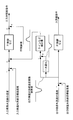
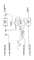
- FIG. 1 is a schematic configuration diagram of a hot water heat pump according to a first embodiment of the present invention. It is a block diagram of the control method of the hot water heat pump concerning a 1st embodiment of the present invention. It is a modification of the schematic block diagram of the hot water heat pump which concerns on 1st Embodiment of this invention. It is a schematic block diagram of the hot water heat pump which concerns on 2nd Embodiment of this invention. It is a block diagram of the control method of the hot water heat pump which concerns on 2nd Embodiment of this invention. It is a schematic block diagram of the hot water heat pump which concerns on 3rd Embodiment of this invention. It is a block diagram of the control method of the hot water heat pump which concerns on 3rd Embodiment of this invention. It is a modification of the block diagram of the control method of the hot water heat pump which concerns on 3rd Embodiment of this invention.
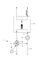
- FIG. 1 shows a schematic configuration diagram of a hot water heat pump according to the first embodiment of the present invention.
- the hot water heat pump 1 includes a hot water heat pump main body 2, a water supply pump 3, and a three-way valve 4.
- the hot water heat pump main body 2 has a thermal output heat exchanger (not shown).
- the hot water heat pump main body 2 is typically a refrigerator capable of operating the heat pump 1, for example, an absorption refrigerator.
- the thermal output heat exchanger draws heat from a heat source system led to the thermal output heat exchanger and outputs thermal heat.
- the thermal output pumped by the thermal output heat exchanger is controlled by a control unit (not shown).
- the heat pumped out by the heat output heat exchanger is added to the hot water system via the heat output heat exchanger.
- the warm heat added to the warm water system is supplied to an external load (not shown) such as a fan coil.
- the water in the heated hot water system (hereinafter referred to as “inlet-side hot water system”) 5 is supplied to the thermal output heat exchanger.
- an inlet side hot water system temperature detector 20 for detecting the temperature of the inlet side hot water system 5 (inlet side hot water system temperature) is provided.
- the temperatures of the upstream inlet-side hot water system 8 and the initial inlet-side hot water system 5 are set to 30 ° C., for example.
- the inlet-side hot water system 5 led to the thermal output heat exchanger obtains heat by the thermal output heat exchanger and is derived from the thermal output heat exchanger.
- an outlet side hot water system temperature detector 21 is provided between the hot water system (hereinafter referred to as “exit side hot water system”) 6 derived from the thermal output heat exchanger and a three-way valve 4 described later.
- the outlet side hot water system 6 is provided with a three-way valve 4 that is a flow rate adjusting valve.
- the partial flow rate (hereinafter referred to as “circulation hot water system”) 7 of the outlet-side hot water system 6 that has been heated is joined to the inlet-side hot water system 5 by controlling the three-way valve 4 by the control unit.
- the outlet-side hot water system 6 that has not been led to the circulating hot water system 7 via the three-way valve 4 is led out of the hot water heat pump 1.
- the circulating hot water system 7 joined to the upstream inlet side hot water system 8 via the three-way valve 4 is supplied with water at a temperature of 75 ° C. by joining with the low temperature, for example, 30 ° C. upstream inlet side hot water system 8. It is led to the heat output heat exchanger via the pump 3.
- the inlet-side hot water system 5 led to the thermal output heat exchanger is added with hot heat drawn from the heat source system.
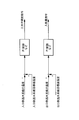
- FIG. 1 The block diagram of the control method of the hot water heat pump which concerns on 1st Embodiment is shown by FIG.
- the temperature of the inlet side hot water system 5 detected by the inlet side hot water system temperature detector 20 does not reach the inlet side hot water system target temperature
- the temperature of the inlet side hot water system 5 becomes the inlet side hot water system target temperature.
- the three-way valve 4 is feedback-controlled so as to reach it.
- the circulating hot water system 7 is circulated from the three-way valve 4 to the thermal output heat exchanger.
- the circulation is circulated from the three-way valve 4 to the thermal output heat exchanger. The flow rate of the hot water system 7 can be reduced.
- the temperature of the outlet-side hot water system 6 detected by the outlet-side hot water system temperature detector 21 has not reached the outlet-side hot water system target temperature
- the temperature of the outlet-side hot water system 6 is the outlet-side hot water system target.
- the thermal output of the hot water heat pump main body 2 is feedback controlled so as to match the temperature.
- the inlet side water supply system 5 can control the heat obtained from the heat output heat exchanger.
- the three-way valve 4 is feedback controlled according to the temperature of the inlet-side hot water system temperature detector 20 detected by the inlet-side hot water system temperature detector 20, and the temperature of the outlet hot water system 6 is detected by the outlet-side hot water system temperature detector 21.
- the inlet-side hot water system (warm water system) 5 obtains the heat directly from the heat output heat exchanger without providing any other equipment. For this reason, since warm heat is directly added to the inlet-side hot water system 5, the temperature increase rate of the outlet-side hot water system (hot water system derived from the thermal output heat exchanger) 6 is increased. Therefore, it is possible to shorten the temperature raising time of the outlet side hot water system 6 while reducing the installation cost of the hot water heat pump 1 and reducing the size of the hot water heat pump 1.
- the hot water heat pump 1 is configured so that a circulating heat system 7 which is a partial flow rate of the outlet side hot water system 6 heated by obtaining heat from the heat output heat exchanger is connected to the upstream inlet side hot water system 8.
- the control part (not shown) which controls a three-way valve is provided so that it may circulate to the inlet side hot water system
- the hot water heat pump 1 of the first embodiment includes a control unit that controls the opening degree of the three-way valve 4 according to the temperature of the inlet side hot water system 5. Therefore, when the temperature of the inlet side hot water system 5 is lower than the target temperature of the inlet side hot water system, the flow rate of the circulating hot water system (the hot water system circulating from the three-way valve 4 to the thermal output heat exchanger) 7 is increased. When the temperature of the inlet side hot water system 5 rises higher than the inlet side hot water system target temperature, the flow rate of the circulating hot water system 7 can be reduced. Therefore, the temperature fluctuation of the inlet side water supply system 5 led to the heat output heat exchanger can be suppressed.
- the hot water heat pump 1 of the first embodiment includes a control unit that controls the thermal output of the hot water heat pump main body 2 according to the temperature of the outlet side hot water system 6.
- a control unit that controls the thermal output of the hot water heat pump main body 2 according to the temperature of the outlet side hot water system 6.
- the hot water heat pump 1 of the first embodiment includes a control unit that performs feedback control of the opening degree and the thermal output of the three-way valve 4. Therefore, even when the temperature of the inlet-side hot water system 5 varies, the temperature of the inlet-side hot water system 5 can be maintained at the inlet-side hot water system target temperature.
- a control unit for feedback control of the thermal output is provided. Therefore, the temperature of the outlet side hot water system 6 can be maintained at the outlet side hot water system target temperature. Therefore, even if it is a case where the temperature change of the exit side hot water system
- the outlet-side hot water system temperature detector 21 is described as being provided in the outlet-side hot water system 6 between the three-way valve 4 and the thermal output heat exchanger.
- the present invention is not limited to this. Instead, as shown in FIG. 3, the outlet side hot water system temperature detector 21 may be provided in the outlet side hot water system downstream of the three-way valve 4.
- the hot water heat pump and the control method of the second embodiment are the first in that the upstream inlet hot water system includes a temperature detector and a flow rate detector at the inlet of the thermal output heat exchanger, and feedforward control is added to the three-way valve.
- the rest is the same as the first embodiment. Therefore, the same configuration and control method as those in the first embodiment are denoted by the same reference numerals and description thereof is omitted.
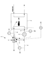
- the schematic block diagram of the hot water heat pump which concerns on 2nd Embodiment is shown by FIG.
- the upstream inlet hot water system 8 is provided with an upstream inlet side hot water system temperature detector 22.
- the upstream inlet side hot water system temperature detector 22 detects the temperature of the upstream inlet hot water system 8 before joining the circulating hot water system 7.
- an inlet-side flow rate detector 23 is provided at the inlet of the thermal output heat exchanger.
- the inlet side flow rate detector 23 detects the flow rate of the inlet side hot water system 5 introduced into the thermal output heat exchanger.
- FIG. 1 The block diagram of the control method of the hot water heat pump which concerns on 2nd Embodiment is shown by FIG.
- the control unit performs feedback control of the three-way valve 4 so that the temperature of the inlet-side hot water system 5 reaches the inlet-side hot water system target temperature.
- a control unit is determined based on a table for the temperature of the upstream inlet side hot water system 8 detected by the upstream inlet side hot water system temperature detector 22 and the flow rate of the inlet side hot water system 5 detected by the inlet side flow rate detector 23. Finds the opening of the three-way valve 4.
- the opening degree of the three-way valve 4 obtained from the table is feedforward controlled by the control unit.
- the control unit is configured so that the temperature of the outlet-side hot water system 6 matches the outlet-side hot water system target temperature.
- the thermal output of the main body 2 is feedback controlled.
- the hot water heat pump 1 of the second embodiment includes an upstream inlet side hot water system (an upstream side hot water system where the hot water system heated by the three-way valve 4 joins) 8 and an inlet side hot water system at the inlet of the thermal output heat exchanger.
- the control part which feedforward-controls the opening degree of the three-way valve 4 according to the flow volume of 5 is provided. Therefore, even if the temperature and flow rate of the upstream inlet-side hot water system (hot water system) 8 change suddenly, the temperature of the inlet-side hot water system 5 guided to the thermal output heat exchanger by controlling the three-way valve 4 Can be controlled. Therefore, the temperature fluctuation of the outlet side hot water system 6 can be suppressed.
- the hot water heat pump and the control method of the third embodiment include a temperature detector in the upstream inlet hot water system, a flow rate detector at the inlet of the thermal output heat exchanger, and a temperature detector in the heat source system introduced into the hot water heat pump body. And is different from the first embodiment in that the control of the temperature compensation term is added to the three-way valve, and the others are the same as in the first embodiment. Therefore, the same configuration and control method as those in the first embodiment are denoted by the same reference numerals and description thereof is omitted.
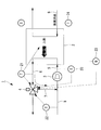
- FIG. 6 shows a schematic configuration diagram of a hot water heat pump according to the third embodiment.
- the upstream inlet side hot water system 8 is provided with a temperature detector 22 for the upstream inlet side hot water system.
- the upstream inlet side hot water system temperature detector 22 detects the temperature of the upstream inlet side hot water system 8.
- An inlet-side flow rate detector 23 is provided at the inlet of the thermal output heat exchanger.
- the inlet side flow rate detector 23 detects the flow rate of the inlet hot water system 5 introduced into the thermal output heat exchanger.
- an inlet side heat source system temperature detector 24 is provided in the heat source system 9 (hereinafter referred to as “inlet side heat source system”) led to the thermal output heat exchanger.
- the inlet side heat source system temperature detector 24 detects the temperature of the inlet side heat source system 9.
- FIG. 1 The block diagram of the control method of the hot water heat pump which concerns on 3rd Embodiment is shown by FIG.
- the control unit performs feedback control of the three-way valve 4 so that the temperature of the inlet-side hot water system 5 reaches the inlet-side hot water system target temperature. To do. Further, the control unit obtains a deviation between the temperature of the inlet side hot water system 5 and the temperature of the outlet side hot water system 6. When the deviation is larger than the predetermined difference, the control unit inserts a first-order lag term.
- control unit controls the three-way valve 4 by adding a temperature compensation term from the temperature of the outlet side hot water system 6 detected by the outlet side hot water system detector 21.
- the temperature compensation term is to compensate so as to reduce the temperature difference between the temperature of the outlet-side hot water system 6 and the outlet-side hot water system target temperature.
- control unit is a table for the temperature of the upstream inlet side hot water system 8 detected by the upstream inlet side hot water system temperature detector 22 and the flow rate of the inlet side hot water system 5 detected by the inlet side flow rate detector 23.
- the opening degree of the three-way valve 4 is obtained, and the opening degree of the three-way valve 4 is feedforward controlled.
- the control unit main body of the hot water heat pump so that the temperature of the outlet-side hot water system 6 matches the outlet-side hot water system target temperature.
- the thermal output of 2 is feedback controlled.
- the hot water heat pump 1 of the third embodiment compensates for the temperature difference (deviation) between the temperature of the outlet side hot water system 6 and the target temperature of the outlet side hot water system so as to decrease from the temperature of the outlet side hot water system 6.
- a control unit for controlling the opening degree of the three-way valve 4. Therefore, even when the temperature of the outlet side hot water system 6 changes rapidly, the temperature of the inlet side hot water system 5 guided to the thermal output heat exchanger by controlling the three-way valve 4 can be controlled. Therefore, the temperature fluctuation of the outlet side hot water system 6 derived from the thermal output heat exchanger can be suppressed.
- the three-way valve 4 is controlled by adding a temperature compensation term from the temperature of the outlet-side hot water system 6 detected by the outlet-side hot water system temperature detector 21, but the present invention is not limited to this. It is not limited to.
- a compensation term may be added to the control of the three-way valve 4.
- FIG. 8 shows a block diagram of a control method of the hot water heat pump in this case as a reference example.
- the control unit When the temperature of the inlet-side hot water system 5 has not reached the inlet-side hot water system target temperature, the control unit performs feedback control of the three-way valve 4 so that the temperature of the inlet-side hot water system 5 reaches the inlet-side hot water system target temperature. To do. Furthermore, the control unit inserts a first-order lag term when the temperature of the inlet-side heat source system 9 is higher or lower than a predetermined temperature. Thereafter, the control unit adds a temperature compensation term to control the three-way valve 4. The temperature compensation term compensates so as to reduce the temperature difference between the temperature of the outlet-side hot water system 6 and the outlet-side hot water system target temperature, and is obtained from the temperature of the inlet-side heat source system 9.
- control unit is a table for the temperature of the upstream inlet side hot water system 8 detected by the upstream inlet side hot water system temperature detector 22 and the flow rate of the inlet side hot water system 5 detected by the inlet side flow rate detector 23.
- the opening degree of the three-way valve 4 is obtained, and the opening degree of the three-way valve 4 is feedforward controlled.
- the three-way valve 4 is controlled by inserting a temporary delay term, but the temporary delay term may be omitted. Moreover, it is good also as what does not add feedforward control.
Landscapes
- Engineering & Computer Science (AREA)
- Physics & Mathematics (AREA)
- Thermal Sciences (AREA)
- Mechanical Engineering (AREA)
- General Engineering & Computer Science (AREA)
- Chemical & Material Sciences (AREA)
- Combustion & Propulsion (AREA)
- Heat-Pump Type And Storage Water Heaters (AREA)
- Steam Or Hot-Water Central Heating Systems (AREA)
Abstract
Priority Applications (4)
| Application Number | Priority Date | Filing Date | Title |
|---|---|---|---|
| EP11750504.0A EP2543935A4 (fr) | 2010-03-05 | 2011-02-22 | Pompe à chaleur pour eau chaude et son procédé de commande |
| KR1020147021495A KR101570019B1 (ko) | 2010-03-05 | 2011-02-22 | 온수 히트 펌프 및 그 제어 방법 |
| CN201180007028.2A CN102725591B (zh) | 2010-03-05 | 2011-02-22 | 热水热泵及其控制方法 |
| US13/520,229 US9664415B2 (en) | 2010-03-05 | 2011-02-22 | Hot-water heat pump and method of controlling the same |
Applications Claiming Priority (2)
| Application Number | Priority Date | Filing Date | Title |
|---|---|---|---|
| JP2010-048886 | 2010-03-05 | ||
| JP2010048886A JP5729910B2 (ja) | 2010-03-05 | 2010-03-05 | 温水ヒートポンプおよびその制御方法 |
Publications (1)
| Publication Number | Publication Date |
|---|---|
| WO2011108392A1 true WO2011108392A1 (fr) | 2011-09-09 |
Family
ID=44542048
Family Applications (1)
| Application Number | Title | Priority Date | Filing Date |
|---|---|---|---|
| PCT/JP2011/053768 Ceased WO2011108392A1 (fr) | 2010-03-05 | 2011-02-22 | Pompe à chaleur pour eau chaude et son procédé de commande |
Country Status (6)
| Country | Link |
|---|---|
| US (1) | US9664415B2 (fr) |
| EP (1) | EP2543935A4 (fr) |
| JP (1) | JP5729910B2 (fr) |
| KR (2) | KR20120104372A (fr) |
| CN (1) | CN102725591B (fr) |
| WO (1) | WO2011108392A1 (fr) |
Cited By (2)
| Publication number | Priority date | Publication date | Assignee | Title |
|---|---|---|---|---|
| CN103703323A (zh) * | 2011-11-11 | 2014-04-02 | 三菱重工业株式会社 | 温水加热系统以及控制装置及控制方法 |
| CN110513930A (zh) * | 2019-09-05 | 2019-11-29 | 四川长虹空调有限公司 | 空气源热泵机组变频压缩机加减载控制方法 |
Families Citing this family (15)
| Publication number | Priority date | Publication date | Assignee | Title |
|---|---|---|---|---|
| JP5729910B2 (ja) * | 2010-03-05 | 2015-06-03 | 三菱重工業株式会社 | 温水ヒートポンプおよびその制御方法 |
| EP2413048B1 (fr) * | 2010-07-30 | 2013-06-05 | Grundfos Management A/S | Unité de chauffage d'eau potable |
| CN104769364B (zh) * | 2012-11-16 | 2017-09-08 | 格兰富控股联合股份公司 | 热平衡机组及其控制方法与控制装置 |
| DE102012024347A1 (de) * | 2012-12-13 | 2014-06-18 | Robert Bosch Gmbh | Heizungsvorrichtung und Verfahren zu deren Betrieb |
| KR101549657B1 (ko) * | 2013-11-08 | 2015-09-03 | 한국에너지기술연구원 | 지역난방 네트워크 간의 열교환 제어 시스템 및 그 방법 |
| FR3046665A1 (fr) * | 2016-01-08 | 2017-07-14 | Elax Dev | Unite de controle pour controler une temperature d'un premier liquide caloporteur en entree d'une pompe a chaleur eau/eau |
| KR101950888B1 (ko) * | 2017-02-02 | 2019-02-21 | 김인수 | 보일러 |
| CN107131651B (zh) * | 2017-04-17 | 2020-06-30 | 广东芬尼克兹节能设备有限公司 | 一种稳定调节水温的装置和方法 |
| CN107504548A (zh) * | 2017-09-18 | 2017-12-22 | 江苏中圣管道工程技术有限公司 | 一种汽水混合集中供热系统 |
| JP6894814B2 (ja) * | 2017-09-21 | 2021-06-30 | 日立建機株式会社 | ハイブリッド式作業機械 |
| CN109442602B (zh) * | 2018-08-27 | 2021-04-13 | 广东芬尼克兹节能设备有限公司 | 一种热泵机组的水路控制系统及其控制方法 |
| CA3060479C (fr) * | 2019-09-20 | 2022-11-15 | Payam Tavakoli | Systeme et methode de controle de la temperature de sortie d'un chauffe-eau |
| CN110726245B (zh) * | 2019-10-08 | 2021-05-25 | 广东纽恩泰新能源科技发展有限公司 | 一种户用变频直热空气能热泵热水器 |
| CN110953688A (zh) * | 2019-12-30 | 2020-04-03 | 格力电器(武汉)有限公司 | 一种供水循环系统及水箱水路测试方法 |
| DE102023212531A1 (de) | 2023-12-12 | 2025-06-12 | Robert Bosch Gesellschaft mit beschränkter Haftung | Verfahren und Wärmepumpensystem |
Citations (7)
| Publication number | Priority date | Publication date | Assignee | Title |
|---|---|---|---|---|
| JPH0375944B2 (fr) | 1985-06-28 | 1991-12-03 | Nippon Telegraph & Telephone | |
| JPH07225062A (ja) | 1994-02-16 | 1995-08-22 | Hitachi Ltd | 吸収式ヒートポンプ |
| JP2842550B2 (ja) | 1994-11-25 | 1999-01-06 | 東京瓦斯株式会社 | 吸収冷温水機 |
| JP2894602B2 (ja) | 1995-10-02 | 1999-05-24 | 東京瓦斯株式会社 | 吸収冷温水機及びその制御方法 |
| JP2005121283A (ja) * | 2003-10-16 | 2005-05-12 | Matsushita Electric Ind Co Ltd | ヒートポンプ給湯機 |
| JP2005257268A (ja) * | 2005-04-21 | 2005-09-22 | Matsushita Electric Ind Co Ltd | ヒートポンプ給湯装置 |
| JP2008249164A (ja) * | 2007-03-29 | 2008-10-16 | Mitsubishi Electric Corp | 給湯装置 |
Family Cites Families (89)
| Publication number | Priority date | Publication date | Assignee | Title |
|---|---|---|---|---|
| US1611764A (en) * | 1921-07-22 | 1926-12-21 | Louis R Mendelson | Indirect water heater |
| US2619326A (en) * | 1949-11-29 | 1952-11-25 | Gen Electric | Fluid heating system, including a heat pump |
| US3490517A (en) * | 1965-08-10 | 1970-01-20 | Nat Service Ind Inc | Dynamically integrated comfort conditioning system |
| US3403723A (en) * | 1965-08-10 | 1968-10-01 | Lithonia Lighting Inc | Dynamically integrated comfort conditioning system |
| US3658244A (en) * | 1970-03-20 | 1972-04-25 | Ranco Inc | Air tempering system |
| SE389188B (sv) * | 1973-12-20 | 1976-10-25 | Projectus Ind Produkter Ab | Forfarande och anordning for vermning av fluider i olika kretsar for skilda foremal medelst en vermepump, innefattande en koldmediekrets med en expansionsventil, en forangare, en kompressor och ett kondensorapparat |
| US4257556A (en) * | 1975-05-07 | 1981-03-24 | Skala Stephen F | Fluid heat transfer system |
| DE2721301A1 (de) * | 1977-05-12 | 1978-11-23 | Geb Entian Anneliese Ohms | Heizungsanlage fuer gebaeude mit einer zweitfeuerstelle |
| CH644460A5 (de) | 1980-02-27 | 1984-07-31 | Aquametro Ag | Anlage zum transport von waerme mittels eines fluides. |
| DE3014029A1 (de) * | 1980-04-11 | 1981-10-22 | Rheinisch-Westfälisches Elektrizitätswerk AG, 4300 Essen | Waermepumpenanlagen fuer heizungszwecke |
| JPS5721726A (en) * | 1980-07-11 | 1982-02-04 | Hitachi Ltd | Heat pump type heater |
| JPS5721727A (en) * | 1980-07-11 | 1982-02-04 | Hitachi Ltd | Heat pump type heater |
| US4341263A (en) * | 1980-11-11 | 1982-07-27 | Morteza Arbabian | Waste water heat recovery apparatus |
| GB2090023B (en) * | 1980-12-22 | 1984-04-18 | British Gas Corp | Central heating control system |
| DE3105373A1 (de) * | 1981-02-13 | 1982-11-11 | Siemens AG, 1000 Berlin und 8000 München | Heizungsanlage |
| DE3302065A1 (de) * | 1982-02-06 | 1983-08-18 | Joh. Vaillant Gmbh U. Co, 5630 Remscheid | Sorptionswaermepumpe |
| DE3207435A1 (de) * | 1982-02-06 | 1983-09-08 | Joh. Vaillant Gmbh U. Co, 5630 Remscheid | Steuer- und regeleinrichtung fuer eine sorptionswaermepumpe |
| JPS6029863B2 (ja) * | 1982-12-10 | 1985-07-12 | 工業技術院長 | 太陽熱利用プラント |
| US4498622A (en) * | 1983-05-23 | 1985-02-12 | Borg-Warner Corporation | Quick recovery heat pump water heater |
| US4522253A (en) * | 1983-08-10 | 1985-06-11 | The Bennett Levin Associates, Inc. | Water-source heat pump system |
| CA1214336A (fr) * | 1983-10-11 | 1986-11-25 | Sven G. Oskarsson | Thermopompe |
| JPS61125540A (ja) * | 1984-11-21 | 1986-06-13 | Fuji Heavy Ind Ltd | 給湯用ヒ−トポンプ装置 |
| DE3608867A1 (de) * | 1986-03-17 | 1987-09-24 | Stiebel Eltron Gmbh & Co Kg | Aufladesteuerung eines waermepumpenbeheizten warmwasserspeichers |
| JPS632357A (ja) * | 1986-06-19 | 1988-01-07 | インタ−ナショナル ビジネス マシ−ンズ コ−ポレ−ション | ヒート・シンク装置 |
| JPS6332224A (ja) * | 1986-07-25 | 1988-02-10 | Takuma Co Ltd | 熱供給システム |
| US4824740A (en) * | 1987-06-15 | 1989-04-25 | International Fuel Cell Corporation | Fuel cell stack cooling system |
| GB8919654D0 (en) * | 1989-08-31 | 1989-10-11 | Worcester Heat Systems Ltd | Improvements in or relating to water heating systems |
| US5115491A (en) * | 1990-12-17 | 1992-05-19 | Maier Perlman | Tempering system for storage tank water heaters utilizing inlet and outlet heat exchanger |
| US5366151A (en) * | 1993-12-27 | 1994-11-22 | Ford Motor Company | Hybrid vehicle fuel vapor management apparatus |
| JP3075944B2 (ja) | 1994-11-29 | 2000-08-14 | 三洋電機株式会社 | 吸収冷温水機 |
| DE19509419A1 (de) * | 1995-03-16 | 1996-09-19 | Klaus Grubert | Zirkulationspumpensteuerung |
| JP3735891B2 (ja) * | 1995-05-26 | 2006-01-18 | 株式会社ノーリツ | 1缶2水路式風呂釜装置 |
| US5613372A (en) * | 1995-05-26 | 1997-03-25 | Dumont Management, Inc. | Heat pump system dehumidifier with secondary water loop |
| US5727396A (en) * | 1995-12-15 | 1998-03-17 | Gas Research Institute | Method and apparatus for cooling a prime mover for a gas-engine driven heat pump |
| US5947373A (en) * | 1996-02-09 | 1999-09-07 | Sanyo Electric Co., Ltd. | Refrigerant circuit with fluid heated refrigerant |
| DE19620399A1 (de) * | 1996-05-21 | 1997-11-27 | Stiebel Eltron Gmbh & Co Kg | Verfahren zum Heizen mit einer Wärmepumpe |
| JP3632357B2 (ja) * | 1997-03-17 | 2005-03-23 | 松下電器産業株式会社 | ヒートポンプ式風呂給湯システム |
| US7147071B2 (en) * | 2004-02-04 | 2006-12-12 | Battelle Energy Alliance, Llc | Thermal management systems and methods |
| US5918805A (en) * | 1998-01-14 | 1999-07-06 | Yankee Scientific, Inc. | Self-powered space heating system |
| US6109346A (en) * | 1998-01-20 | 2000-08-29 | Hill; Gary G. | Waste heat auxiliary tank system method and apparatus |
| CN2392132Y (zh) | 1999-09-23 | 2000-08-16 | 杨民 | 热水器用恒温出水装置 |
| US6560978B2 (en) * | 2000-12-29 | 2003-05-13 | Thermo King Corporation | Transport temperature control system having an increased heating capacity and a method of providing the same |
| JP3969154B2 (ja) * | 2001-08-24 | 2007-09-05 | 株式会社デンソー | 貯湯式給湯器 |
| JP2003106653A (ja) | 2001-09-28 | 2003-04-09 | Kansai Electric Power Co Inc:The | ヒートポンプ式給湯装置 |
| JP3742356B2 (ja) * | 2002-03-20 | 2006-02-01 | 株式会社日立製作所 | ヒートポンプ給湯機 |
| FR2847972B1 (fr) * | 2002-11-29 | 2005-03-04 | Realisation Mecaniques Engenee | Echangeur de chaleur et dispositif de production d'eau chaude sanitaire |
| JP2004268752A (ja) * | 2003-03-10 | 2004-09-30 | Denso Corp | 熱管理システム |
| JP3956925B2 (ja) | 2003-09-24 | 2007-08-08 | 松下電器産業株式会社 | 給湯装置 |
| JP4304601B2 (ja) * | 2004-01-20 | 2009-07-29 | 株式会社ノーリツ | 貯留式給湯装置およびコージェネレーションシステム |
| US6862894B1 (en) * | 2004-02-04 | 2005-03-08 | Donald R. Miles | Adaptive auxiliary condensing device and method |
| DE102004018034B4 (de) * | 2004-04-14 | 2014-07-24 | Stiebel Eltron Gmbh & Co. Kg | Verfahren zur Einschaltung einer Wärmepumpe in Verbindung mit einem Brauchwasserspeicher für Wärmepumpen |
| JP4279725B2 (ja) * | 2004-06-03 | 2009-06-17 | 関西電力株式会社 | ヒートポンプ式給湯暖房装置 |
| JP2006083720A (ja) * | 2004-09-14 | 2006-03-30 | Honda Motor Co Ltd | コジェネレーション装置 |
| US8567689B2 (en) * | 2004-09-17 | 2013-10-29 | Carrier Corporation | Sanitary operator of a hot water heat pump |
| JP2006177625A (ja) * | 2004-12-24 | 2006-07-06 | Corona Corp | 貯湯式給湯風呂装置 |
| WO2007004460A1 (fr) * | 2005-06-30 | 2007-01-11 | Toshiba Carrier Corporation | Dispositif d’alimentation en eau chaude d’une pompe à chaleur |
| GB0522307D0 (en) * | 2005-11-01 | 2005-12-07 | Zenex Technologies Ltd | A burner and heat exchanger combination, and a boiler including such a burner and heat exchanger combination |
| JP3966889B2 (ja) * | 2005-12-28 | 2007-08-29 | シャープ株式会社 | ヒートポンプ式給湯機 |
| DE102006017198A1 (de) * | 2006-04-12 | 2007-10-25 | Joachim Kiefer | Wärmespeicheranlage |
| JP4857903B2 (ja) * | 2006-05-17 | 2012-01-18 | ダイキン工業株式会社 | 給湯機 |
| KR101270615B1 (ko) * | 2006-07-25 | 2013-06-07 | 엘지전자 주식회사 | 코제너레이션 및 그 제어 방법 |
| KR101270616B1 (ko) * | 2006-07-27 | 2013-06-07 | 엘지전자 주식회사 | 코제너레이션 |
| WO2008025849A2 (fr) * | 2006-08-31 | 2008-03-06 | Colipu A/S | Système à air solaire doté d'une pompe à chaleur |
| KR100805551B1 (ko) * | 2006-10-17 | 2008-02-20 | 주식회사 경동나비엔 | 보일러 배기연도의 응결방지방법 |
| US8955763B2 (en) * | 2007-10-04 | 2015-02-17 | Consolidated Edison Company Of New York, Inc. | Building heating system and method of operation |
| JPWO2009098751A1 (ja) * | 2008-02-04 | 2011-05-26 | 三菱電機株式会社 | 空調給湯複合システム |
| JP4859874B2 (ja) * | 2008-05-12 | 2012-01-25 | 三菱重工業株式会社 | 冷却海水移送ポンプの回転数制御装置 |
| JP2009281650A (ja) * | 2008-05-21 | 2009-12-03 | Daikin Ind Ltd | 暖房システム |
| JP4949325B2 (ja) * | 2008-06-03 | 2012-06-06 | 本田技研工業株式会社 | コージェネレーション装置 |
| JP5171410B2 (ja) * | 2008-06-11 | 2013-03-27 | リンナイ株式会社 | 温水供給システム |
| KR101329509B1 (ko) * | 2008-08-04 | 2013-11-13 | 엘지전자 주식회사 | 히트펌프 연동 온수 순환 시스템 및 제어 방법 |
| US8657207B2 (en) * | 2008-08-26 | 2014-02-25 | Lg Electronics Inc. | Hot water circulation system associated with heat pump and method for controlling the same |
| JP5713536B2 (ja) * | 2009-01-05 | 2015-05-07 | 三菱電機株式会社 | ヒートポンプ式給湯器 |
| KR20110106933A (ko) * | 2009-01-20 | 2011-09-29 | 다이킨 고교 가부시키가이샤 | 물 열교환기 및 온수 열원 장치 |
| JP5551882B2 (ja) * | 2009-02-24 | 2014-07-16 | ダイキン工業株式会社 | ヒートポンプシステム |
| JP2010196953A (ja) * | 2009-02-24 | 2010-09-09 | Daikin Ind Ltd | ヒートポンプシステム |
| JP5200996B2 (ja) * | 2009-02-24 | 2013-06-05 | ダイキン工業株式会社 | ヒートポンプシステム |
| JP5316074B2 (ja) * | 2009-02-24 | 2013-10-16 | ダイキン工業株式会社 | ヒートポンプシステム |
| JP2010196946A (ja) * | 2009-02-24 | 2010-09-09 | Daikin Ind Ltd | ヒートポンプシステム |
| JP5174950B2 (ja) * | 2009-03-26 | 2013-04-03 | 三菱電機株式会社 | 温度調整装置、流体供給システム、暖房システム、温度調整装置の取付方法及び流体供給方法 |
| US20120000236A1 (en) * | 2009-04-13 | 2012-01-05 | Panasonic Corporation | Heat pump heating system |
| FR2947895A3 (fr) * | 2009-07-07 | 2011-01-14 | Bosch Gmbh Robert | Installation de chauffage et/ou de fourniture d'eau chaude sanitaire |
| FR2947896B1 (fr) * | 2009-07-07 | 2016-07-01 | Bosch Gmbh Robert | Installation de chauffage et/ou de fourniture d'eau chaude sanitaire |
| JP5570531B2 (ja) * | 2010-01-26 | 2014-08-13 | 三菱電機株式会社 | ヒートポンプ装置 |
| JP5729910B2 (ja) * | 2010-03-05 | 2015-06-03 | 三菱重工業株式会社 | 温水ヒートポンプおよびその制御方法 |
| WO2011129248A1 (fr) * | 2010-04-15 | 2011-10-20 | 三菱電機株式会社 | Dispositif de commande pour système de chauffe-eau, programme pour commander un système de chauffe-eau, et procédé pour faire fonctionner un système de chauffe-eau |
| JP4947197B2 (ja) * | 2010-07-15 | 2012-06-06 | ダイキン工業株式会社 | ヒートポンプシステム |
| JP5375908B2 (ja) * | 2011-09-15 | 2013-12-25 | ダイキン工業株式会社 | ヒートポンプ給湯機 |
| KR102025740B1 (ko) * | 2012-10-29 | 2019-09-26 | 삼성전자주식회사 | 히트펌프장치 |
-
2010
- 2010-03-05 JP JP2010048886A patent/JP5729910B2/ja active Active
-
2011
- 2011-02-22 KR KR1020127018525A patent/KR20120104372A/ko not_active Ceased
- 2011-02-22 EP EP11750504.0A patent/EP2543935A4/fr not_active Withdrawn
- 2011-02-22 WO PCT/JP2011/053768 patent/WO2011108392A1/fr not_active Ceased
- 2011-02-22 KR KR1020147021495A patent/KR101570019B1/ko active Active
- 2011-02-22 CN CN201180007028.2A patent/CN102725591B/zh active Active
- 2011-02-22 US US13/520,229 patent/US9664415B2/en active Active
Patent Citations (7)
| Publication number | Priority date | Publication date | Assignee | Title |
|---|---|---|---|---|
| JPH0375944B2 (fr) | 1985-06-28 | 1991-12-03 | Nippon Telegraph & Telephone | |
| JPH07225062A (ja) | 1994-02-16 | 1995-08-22 | Hitachi Ltd | 吸収式ヒートポンプ |
| JP2842550B2 (ja) | 1994-11-25 | 1999-01-06 | 東京瓦斯株式会社 | 吸収冷温水機 |
| JP2894602B2 (ja) | 1995-10-02 | 1999-05-24 | 東京瓦斯株式会社 | 吸収冷温水機及びその制御方法 |
| JP2005121283A (ja) * | 2003-10-16 | 2005-05-12 | Matsushita Electric Ind Co Ltd | ヒートポンプ給湯機 |
| JP2005257268A (ja) * | 2005-04-21 | 2005-09-22 | Matsushita Electric Ind Co Ltd | ヒートポンプ給湯装置 |
| JP2008249164A (ja) * | 2007-03-29 | 2008-10-16 | Mitsubishi Electric Corp | 給湯装置 |
Non-Patent Citations (1)
| Title |
|---|
| See also references of EP2543935A4 |
Cited By (5)
| Publication number | Priority date | Publication date | Assignee | Title |
|---|---|---|---|---|
| CN103703323A (zh) * | 2011-11-11 | 2014-04-02 | 三菱重工业株式会社 | 温水加热系统以及控制装置及控制方法 |
| EP2778555A4 (fr) * | 2011-11-11 | 2016-01-06 | Mitsubishi Heavy Ind Ltd | Système de chauffage d'eau chaude, dispositif de commande et procédé de commande |
| CN103703323B (zh) * | 2011-11-11 | 2016-06-08 | 三菱重工业株式会社 | 温水加热系统以及控制装置及控制方法 |
| CN110513930A (zh) * | 2019-09-05 | 2019-11-29 | 四川长虹空调有限公司 | 空气源热泵机组变频压缩机加减载控制方法 |
| CN110513930B (zh) * | 2019-09-05 | 2021-07-13 | 四川长虹空调有限公司 | 空气源热泵机组变频压缩机加减载控制方法 |
Also Published As
| Publication number | Publication date |
|---|---|
| JP2011185477A (ja) | 2011-09-22 |
| KR20120104372A (ko) | 2012-09-20 |
| KR20140108590A (ko) | 2014-09-11 |
| US9664415B2 (en) | 2017-05-30 |
| US20120280052A1 (en) | 2012-11-08 |
| JP5729910B2 (ja) | 2015-06-03 |
| EP2543935A1 (fr) | 2013-01-09 |
| CN102725591A (zh) | 2012-10-10 |
| KR101570019B1 (ko) | 2015-11-17 |
| CN102725591B (zh) | 2015-01-14 |
| EP2543935A4 (fr) | 2013-11-20 |
Similar Documents
| Publication | Publication Date | Title |
|---|---|---|
| JP5729910B2 (ja) | 温水ヒートポンプおよびその制御方法 | |
| US20200217520A1 (en) | Controlled hydronic distribution system | |
| US9010280B2 (en) | Hot-water supply system | |
| EP2610558B1 (fr) | Systeme de pompe a chaleur et procede de commande d'une pompe a chaleur d'un systeme de ppompe a chaleur | |
| JP5905077B2 (ja) | 空気調和システム | |
| KR100985391B1 (ko) | 개별난방 제어 시스템에서 난방 부하 변동에 따른 보일러의제어방법 및 이를 이용한 개별난방 제어 시스템 | |
| JP4620746B2 (ja) | クリーンルーム用の給気温度制御システム | |
| KR20220012301A (ko) | 온도 제어 시스템 및 온도 제어 방법 | |
| KR101506548B1 (ko) | 보일러의 난방 제어 방법 및 제어 장치 | |
| JP2020064371A5 (fr) | ||
| JP5496771B2 (ja) | 温度制御装置を用いた温度制御方法 | |
| JP2009014218A (ja) | 温水暖房装置 | |
| JP2002280036A (ja) | 燃料電池の冷却制御装置 | |
| JP2017067422A (ja) | ブライン供給装置 | |
| EP3525060B1 (fr) | Module de commande d'écoulement et procédé pour réguler l'écoulement dans un système hydronique | |
| RU2006128053A (ru) | Способ автоматического регулирования расхода тепла в тепловой сети при двухконтурной системе отопления | |
| JP5247621B2 (ja) | 給湯暖房システム | |
| JP5254660B2 (ja) | 温水暖房装置の制御方法 | |
| JP2014001880A (ja) | 貯湯式給湯機 | |
| JP5287370B2 (ja) | 暖房装置 | |
| JP4600139B2 (ja) | 空調装置及びその制御方法 | |
| CN110953719A (zh) | 一种防止燃气热水器采暖出水温度过高的控制方法 | |
| WO2018180903A1 (fr) | Dispositif de chauffage et procédé de chauffage | |
| JP2009236465A (ja) | 送水圧制御システムおよび送水圧制御方法 | |
| JP2007107842A (ja) | 温水システム |
Legal Events
| Date | Code | Title | Description |
|---|---|---|---|
| WWE | Wipo information: entry into national phase |
Ref document number: 201180007028.2 Country of ref document: CN |
|
| 121 | Ep: the epo has been informed by wipo that ep was designated in this application |
Ref document number: 11750504 Country of ref document: EP Kind code of ref document: A1 |
|
| WWE | Wipo information: entry into national phase |
Ref document number: 13520229 Country of ref document: US |
|
| REEP | Request for entry into the european phase |
Ref document number: 2011750504 Country of ref document: EP |
|
| WWE | Wipo information: entry into national phase |
Ref document number: 2011750504 Country of ref document: EP |
|
| ENP | Entry into the national phase |
Ref document number: 20127018525 Country of ref document: KR Kind code of ref document: A |
|
| NENP | Non-entry into the national phase |
Ref country code: DE |