WO2011108531A1 - グロメット - Google Patents
グロメット Download PDFInfo
- Publication number
- WO2011108531A1 WO2011108531A1 PCT/JP2011/054604 JP2011054604W WO2011108531A1 WO 2011108531 A1 WO2011108531 A1 WO 2011108531A1 JP 2011054604 W JP2011054604 W JP 2011054604W WO 2011108531 A1 WO2011108531 A1 WO 2011108531A1
- Authority
- WO
- WIPO (PCT)
- Prior art keywords
- leg
- shaft body
- grommet
- contact
- main body
- Prior art date
- Legal status (The legal status is an assumption and is not a legal conclusion. Google has not performed a legal analysis and makes no representation as to the accuracy of the status listed.)
- Ceased
Links
Images





Classifications
-
- F—MECHANICAL ENGINEERING; LIGHTING; HEATING; WEAPONS; BLASTING
- F16—ENGINEERING ELEMENTS AND UNITS; GENERAL MEASURES FOR PRODUCING AND MAINTAINING EFFECTIVE FUNCTIONING OF MACHINES OR INSTALLATIONS; THERMAL INSULATION IN GENERAL
- F16B—DEVICES FOR FASTENING OR SECURING CONSTRUCTIONAL ELEMENTS OR MACHINE PARTS TOGETHER, e.g. NAILS, BOLTS, CIRCLIPS, CLAMPS, CLIPS OR WEDGES; JOINTS OR JOINTING
- F16B19/00—Bolts without screw-thread; Pins, including deformable elements; Rivets
- F16B19/04—Rivets; Spigots or the like fastened by riveting
- F16B19/08—Hollow rivets; Multi-part rivets
- F16B19/10—Hollow rivets; Multi-part rivets fastened by expanding mechanically
-
- F—MECHANICAL ENGINEERING; LIGHTING; HEATING; WEAPONS; BLASTING
- F16—ENGINEERING ELEMENTS AND UNITS; GENERAL MEASURES FOR PRODUCING AND MAINTAINING EFFECTIVE FUNCTIONING OF MACHINES OR INSTALLATIONS; THERMAL INSULATION IN GENERAL
- F16B—DEVICES FOR FASTENING OR SECURING CONSTRUCTIONAL ELEMENTS OR MACHINE PARTS TOGETHER, e.g. NAILS, BOLTS, CIRCLIPS, CLAMPS, CLIPS OR WEDGES; JOINTS OR JOINTING
- F16B19/00—Bolts without screw-thread; Pins, including deformable elements; Rivets
- F16B19/04—Rivets; Spigots or the like fastened by riveting
- F16B19/08—Hollow rivets; Multi-part rivets
- F16B19/10—Hollow rivets; Multi-part rivets fastened by expanding mechanically
- F16B19/1027—Multi-part rivets
- F16B19/1036—Blind rivets
- F16B19/1081—Blind rivets fastened by a drive-pin
Definitions
- the present invention relates to an improvement of a grommet including a shaft body and a main body into which the shaft body is pushed.
- grommet which is also called a pingromet composed of a shaft body and a body into which the shaft body is pushed.
- a grommet expands the leg portion by pushing the shaft body into the main body from a state in which the leg portion of the main body is inserted through the through hole formed in the object to be fastened. It has a structure that can be fastened to objects.
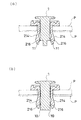
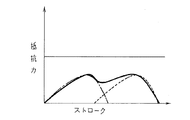
- FIG. 15 shows the concept.
- the horizontal axis represents the pin pushing stroke amount, and the stroke amount increases toward the right.
- the vertical axis represents the indentation resistance.
- the alternate long and short dash line indicates the indentation resistance force that is considered to arise from the leg that positions the expansion point on the distal end side of the leg, and the broken line indicates the expansion point on the base side of the leg. This is the push-in resistance force that is considered to be generated from the positioned leg, and the solid line shows the combined resistance force of these two resistance forces.
- the main problem to be solved by the present invention is that the pushing resistance of the shaft body against the main body constituting the grommet is made as small as possible without impairing the function of this type of grommet.
- the grommet has a shaft body and a leg portion that has a head portion and is expanded by elastic deformation by the shaft body pushed from the head side.
- a grommet consisting of a body,
- the shaft body includes a first abutting portion that abuts against the abutted portion of the leg portion by the pushing and a second abutting portion that is positioned on the rear side of the pushing from the first abutting portion.
- a part of the leg part is expanded by the first contact part, another part of the leg part is expanded by further pushing the shaft body.
- the contacted part is a protrusion protruding inward of the leg part, and the first contact part or the second contact part is brought into contact with the protrusion by pushing the shaft body.
- both contact portions are formed so as to create a certain angle deviation in the circumferential direction of the shaft body between the formation portion of the first contact portion and the formation location of the second contact portion in the shaft body. This is one of the preferred embodiments.
- the leg portion In the state where the first contact portion of the shaft body is not in contact with the contacted portion, the leg portion is not elastically deformed. Next, when the shaft is pushed to a position where the first abutting portion is brought into contact with the abutted portion, only a part of the leg portion is expanded by elastic deformation. The elastic deformation of the other part of the leg does not occur until the part of the leg is fully expanded. Then, when the shaft is pushed to a position where the second contact portion is brought into contact with the contacted portion, the other part of the leg portion is expanded by elastic deformation. As a result, the grommet clamps the fastening object between the head and the leg, and fastens the fastening object to the fastening object.
- the cross-sectional contour shape of the leg portion of the main body should approximately follow the virtual circular arc on the outside of the leg portion, and substantially follow the side of the virtual square on the inside of the leg portion.
- the leg portion can be easily expanded by elastic deformation by pushing the shaft body.
- the pushing resistance of the shaft body against the main body constituting the grommet can be reduced as much as possible without impairing the function of the grommet.
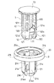
- FIG. 1 is an exploded perspective view of a grommet according to one embodiment of the present invention.
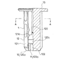
- FIG. 2 is a partially broken side view of the shaft body constituting the grommet.
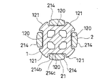
- FIG. 3 is a cross-sectional view of the grommet at the position corresponding to the line AA in FIG.
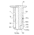
- FIG. 4 is a partially cutaway side view of the shaft body constituting the grommet, and shows the shaft body from a direction different from FIG. 2 by 90 degrees.
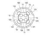
- FIG. 5 is a bottom view of the shaft constituting the grommet.
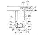
- FIG. 6 is a partially broken side view of the main body constituting the grommet.
- FIG. 7 is a plan view of the main body constituting the grommet.
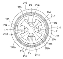
- FIG. 8 is a bottom view of the main body constituting the grommet.
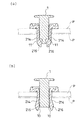
- FIG. 9 is a cross-sectional view showing a state in which the main body constituting the grommet is inserted into the through hole of the object to be fastened.
- FIG. 9 is different from FIG.
- FIG. 10 is a cross-sectional view of the grommet in the state of FIGS.
- FIG. 11 is a cross-sectional configuration diagram illustrating a state in which the shaft body starts to be pushed into the main body from the states of FIGS. 9A and 9B, and FIG. 11B differs in cross-sectional position by 90 degrees from FIG.
- FIG. 12 is a cross-sectional configuration diagram showing a state in which the shaft body is further pushed into the main body from the states of FIGS. 11 (a) and 11 (b).
- FIG. 12 (b) differs from FIG.
- FIG. 13 is a cross-sectional configuration diagram illustrating a state where the shaft body is fully pushed into the main body, and the cross-sectional position of FIG.
- FIG. 14 is a conceptual diagram showing the correlation between the pushing stroke amount of the shaft body and the pushing resistance in the grommet according to the present invention.
- FIG. 15 is a conceptual diagram showing the correlation between the pushing stroke amount of the shaft body and the pushing resistance in the conventional grommet.
- the grommet according to this embodiment includes a shaft body 1 and a main body 2 into which the shaft body 1 is pushed, and the leg portion 21 of the main body 2 is inserted into a through hole Pa formed in the fastening object P. Therefore, by pushing the shaft body 1 into the main body 2, the leg portion 21 is expanded and fastened to the fastening object P.
- a grommet is configured such that a plurality of fastening objects P each having the through holes Pa are overlapped with each other so that the through holes Pa communicate with each other.
- the plurality of fastening objects P are used to be fastened together through grommets by inserting the leg portion 21 and expanding the same.
- the main body 2 includes a leg portion 21 that has a head portion 20 and is expanded by elastic deformation by the shaft body 1 pushed from the head portion 20 side.
- the head 20 is configured to have a disk shape having an outer diameter larger than that of the through hole Pa.
- the leg portion 21 is configured to have a thickness that can be inserted into the through hole Pa.
- the leg 21 has a leg base 211 integrally connected to one surface of the head 20 and protrudes in a direction perpendicular to the one surface.
- the head 20 is formed with a receiving hole 20 a of the circular shaft body 1.
- the leg portion 21 is composed of four elastic leg pieces 214, 214... Of the same size and shape having an elongated plate shape having wide inner and outer surfaces, and the shaft body 1 surrounded by the four elastic leg pieces 214, 214.
- the receiving space 213 communicates with the receiving hole 20a.
- One end of each elastic leg piece 214 is integrally connected to the hole edge portion of the receiving hole 20a to form the leg base portion 211 by this base portion, and the leg end 212 of the leg portion 21 by the other end. It is arranged in. A substantially equal interval is formed between the adjacent elastic leg pieces 214.
- one end of the elastic leg piece 214 is integrally connected to the protruding end of the connecting portion 215 protruding inward from the hole edge of the receiving hole 20a.
- the connecting portion 215 is configured to have a width substantially equal to that of the elastic leg piece 214.
- a protruding portion 216 protruding inward of the leg portion 21 is formed on the other end side of each elastic leg piece 214.
- the receiving space 213 is narrowed on the leg terminal 212 side of the leg portion 21 by the protrusion 216 of each elastic leg piece 214.
- the protrusion 216 includes an inclined surface 216a facing the head 20 side.
- a plane 216 c parallel to a center line (not shown) of the leg 21 is formed between the top 216 b of the protrusion 216 and the other end of the elastic leg piece 214.
- an inclined guide surface 214a is formed on the other end side in a direction that narrows the outer diameter of the leg portion 21 toward the other end. The inclined guide surface 214a allows the leg portion 21 of the main body 2 to be smoothly inserted into the through hole Pa of the object P to be fastened.
- the cross-sectional contour shape of the leg portion 21 substantially follows an arc of a virtual circle outside the leg portion 21 and substantially follows a side of a virtual square inside the leg portion 21. It is. That is, each of the elastic leg pieces 214 has a curved surface 214b whose outer surface follows the arc of the virtual circle and a flat surface 214c whose inner surface follows the side of the virtual square. (FIG. 7, FIG. 8, FIG. 10)
- the shaft body is compared with the case where the cross-sectional contour shape of the leg 21 is configured to follow the virtual circular arc both inside and outside. By pushing 1 in, the leg portion 21 is easily expanded by elastic deformation.
- the shaft body 1 includes the first abutting portion 10 that abuts against the abutted portion with the protruding portion 216 of the leg 21 as the abutted portion by the pushing, and the first abutting portion. And a second abutting portion 11 positioned on the rear side of the push-in relative to 10. And after expanding a part of leg part 21 by this 1st contact part 10, the 2nd contact part 11 is contact
- the leg 21 is not elastically deformed when the first contact portion 10 of the shaft body 1 is not in contact with the contacted portion.
- FIGS. 9A and 9B Next, when the shaft body 1 is pushed to a position where the first contact portion 10 is brought into contact with the contacted portion, only a part of the leg portion 21 is expanded by elastic deformation. Is done. In the illustrated example, at this time, of the four elastic leg pieces 214, 214... Constituting the leg portion 21, only two elastic leg pieces 214 located back to back are bent outward. (FIGS. 11A and 11B) Until the part of the leg 21 is fully expanded, elastic deformation occurs in the remaining two elastic leg pieces 214 which are the other part of the leg 21. There is no such thing.
- FIG. 14 shows the concept.
- the horizontal axis represents the pushing stroke amount of the shaft body 1, and the stroke amount increases toward the right.
- the vertical axis represents the indentation resistance.
- the shaft body 1 includes a main body portion 12 having a substantially prismatic shape and a disk-shaped portion 13. One end of the main body portion 12 is integrally connected to one surface of the disk-shaped portion 13.
- the main body portion 12 is configured to have a thickness that can be inserted into the receiving space 213 of the leg portion 21 through the receiving hole 20 a of the main body 2.
- the disk-shaped part 13 has an outer diameter larger than the thickness of the main body part 12, and the shaft body 1 can be pushed into the main body 2 to a position where the disk-shaped part 13 abuts against the other surface of the head 20 of the main body 2. It is like that.
- the receiving hole 20 a is closed by the disc-shaped portion 13 at a position where the shaft body 1 is fully pushed into the main body 2.
- the main body portion 12 of the shaft body 1 is configured so that the cross-sectional shape of the main body portion 12 substantially follows the virtual quadrangle at each position of the main body portion 12. That is, the main body portion 12 of the shaft body 1 includes four side surface portions 120, 120.
- the corner portions 121 between the side surface portions 120 are configured to have a rib shape that extends long in the axial direction of the shaft body 1, and each side surface portion 120 is between the left and right corner portions 121 and has a groove. It has a shape.
- the distance between the left and right corners 121 is substantially the same as the width dimension of the elastic leg piece 214.
- each elastic leg piece 214 is placed in the left and right corner parts 121 that surround one side part 120, respectively.
- the shaft body 1 is introduced into the receiving space 213 from the other end side through the receiving hole 20a.
- the distance between the two side portions 120 and 120 at the back-to-back position of the shaft body 1 is the distance between the inner surfaces configured as the flat surfaces 214 c of the two elastic leg pieces 214 and 214 at the opposite positions of the leg portion 21 of the main body 2. It is almost the same as the distance.
- the other end of the main body 12 of the shaft body 1 serving as a pushing tip is formed between the adjacent corner portions 121 so as to open outward at the other end of the shaft body 1.
- a recess 122 is formed to retreat the terminal 120a from the other end of the main body 12 toward the rear side of the shaft body 1 being pushed.
- the distance between the bottom surfaces of the two recesses 122 and 122 is smaller than the distance between the protrusions 216 of the two elastic leg pieces 214 at the opposing positions constituting the leg portion 21 of the main body 2.
- the second contact portion 11 is constituted by the terminal of the side surface portion 120 whose terminal 120 a is retracted by the recess 122, and the terminal of the other side surface portion 120 is formed.
- the first contact portion 10 is configured by 120a.
- the second contact portion 11 is formed at a position 90 degrees different from the first contact portion 10.
- the terminal portion protrudes outward as the engaging portion 120c from the intermediate portion 120b of the side surface portion 120 that is retracted from the terminal 120a by the recess 122, and the second contact portion 11 and the elastic leg piece 214 expanded by abutting the protrusion 216 so that the top portion 216b of the protrusion 216 slightly bends back at a position beyond the terminal portion so that the top portion 216b is caught by the engaging portion 120c. It has become. (Fig. 13 (a) (b))
- a concave portion 121a that is recessed from the side surface portion 120 side is formed, and by introducing a part of the shaft body 1 into the main body 2 to a position where the edge portion of the connecting portion 215 enters the concave portion 121a, The main body 2 and the shaft body 1 can be temporarily engaged with each other in a state where the first contact portion 10 is not in contact with the protrusion 216.
- the edge portion of the connecting portion 215 comes out of the recess 121a, and the pushing-in of the shaft body 1 is allowed.
Landscapes
- Engineering & Computer Science (AREA)
- General Engineering & Computer Science (AREA)
- Mechanical Engineering (AREA)
- Insertion Pins And Rivets (AREA)
- Automotive Seat Belt Assembly (AREA)
- Buckles (AREA)
Abstract
Description
軸体は、前記押し込みにより脚部の被当接部に当接される第一当接部と、この第一当接部よりも押し込み後方側に位置される第二当接部とを備えており、
第一当接部により脚部の一部を拡開させた後、さらに軸体を押し込むことにより脚部の他の一部が拡開されるようにしてあるものとした。
Claims (4)
- 軸体と、頭部を有すると共にこの頭部側から押し込まれる前記軸体により弾性変形によって拡開される脚部を備えた本体とよりなるグロメットであって、
軸体は、前記押し込みにより脚部の被当接部に当接される第一当接部と、この第一当接部よりも押し込み後方側に位置される第二当接部とを備えており、
第一当接部により脚部の一部を拡開させた後、さらに軸体を押し込むことにより脚部の他の一部が拡開されるようにしてあることを特徴とするグロメット。 - 被当接部は脚部の内方に突き出す突部であり、軸体の押し込みによりこの突部に第一当接部又は第二当接部が当接されるようになっていることを特徴とする請求項1に記載のグロメット。
- 軸体における第一当接部の形成箇所と第二当接部の形成箇所との間にこの軸体の周方向において一定角度分のズレを作るようにして両当接部を形成させてなることを特徴とする請求項1又は請求項2に記載のグロメット。
- 本体の脚部の横断面輪郭形状を、この脚部の外側においては仮想の円の円弧に略倣い、かつ、この脚部の内側においては仮想の四角形の辺に略倣うようにしてあることを特徴とする請求項1~請求項3のいずれか1項に記載のグロメット。
Priority Applications (3)
| Application Number | Priority Date | Filing Date | Title |
|---|---|---|---|
| US13/582,347 US9016993B2 (en) | 2010-03-03 | 2011-03-01 | Grommet |
| CN201180012030.9A CN102782341B (zh) | 2010-03-03 | 2011-03-01 | 卡扣 |
| EP11750641.0A EP2543895B1 (en) | 2010-03-03 | 2011-03-01 | Push rivet |
Applications Claiming Priority (2)
| Application Number | Priority Date | Filing Date | Title |
|---|---|---|---|
| JP2010-046316 | 2010-03-03 | ||
| JP2010046316A JP5307053B2 (ja) | 2010-03-03 | 2010-03-03 | グロメット |
Publications (1)
| Publication Number | Publication Date |
|---|---|
| WO2011108531A1 true WO2011108531A1 (ja) | 2011-09-09 |
Family
ID=44542182
Family Applications (1)
| Application Number | Title | Priority Date | Filing Date |
|---|---|---|---|
| PCT/JP2011/054604 Ceased WO2011108531A1 (ja) | 2010-03-03 | 2011-03-01 | グロメット |
Country Status (5)
| Country | Link |
|---|---|
| US (1) | US9016993B2 (ja) |
| EP (1) | EP2543895B1 (ja) |
| JP (1) | JP5307053B2 (ja) |
| CN (1) | CN102782341B (ja) |
| WO (1) | WO2011108531A1 (ja) |
Cited By (1)
| Publication number | Priority date | Publication date | Assignee | Title |
|---|---|---|---|---|
| CN103827517A (zh) * | 2011-09-16 | 2014-05-28 | 株式会社利富高 | 紧固件 |
Families Citing this family (10)
| Publication number | Priority date | Publication date | Assignee | Title |
|---|---|---|---|---|
| JP6059532B2 (ja) | 2012-12-28 | 2017-01-11 | 株式会社ニフコ | クリップ |
| US9528540B2 (en) | 2014-08-12 | 2016-12-27 | Newfrey Llc | Insertion-locking pin and grommet and related methods |
| JP1533618S (ja) * | 2015-03-20 | 2015-09-14 | ||
| WO2017127385A1 (en) * | 2016-01-19 | 2017-07-27 | Safariland, Llc | Quick disconnect coupling |
| KR102295273B1 (ko) * | 2018-07-06 | 2021-08-27 | 일리노이즈 툴 워크스 인코포레이티드 | 패스너 조립체 |
| US10900513B2 (en) | 2019-04-02 | 2021-01-26 | Newfrey Llc | Re-usable one-push pin and grommet fastener |
| USD942955S1 (en) * | 2019-12-19 | 2022-02-08 | Corning Research & Development Corporation | Cap for an adapter |
| CN111609013A (zh) * | 2020-05-29 | 2020-09-01 | 京信通信技术(广州)有限公司 | 一种止退型铆钉和天线 |
| US12326163B2 (en) | 2022-09-07 | 2025-06-10 | Newfrey Llc | Pin and grommet fastener including pin and grommet having panel retention fingers and pin retention fingers that cooperate with one another to define pin receptacle for receiving the pin |
| US12565771B2 (en) | 2022-10-07 | 2026-03-03 | Black & Decker Inc. | CIP metal actuated deck insert |
Citations (7)
| Publication number | Priority date | Publication date | Assignee | Title |
|---|---|---|---|---|
| JPH0192508U (ja) * | 1987-12-14 | 1989-06-16 | ||
| JPH0669417U (ja) * | 1993-03-12 | 1994-09-30 | ポップリベット・ファスナー株式会社 | クリップ |
| JPH1030622A (ja) * | 1996-07-16 | 1998-02-03 | Piolax Inc | ファスナ |
| JP2005188579A (ja) * | 2003-12-25 | 2005-07-14 | Nippon Pop Rivets & Fasteners Ltd | パネル等の固定具 |
| JP2006046537A (ja) * | 2004-08-05 | 2006-02-16 | Nifco Inc | 留め具 |
| JP4201217B2 (ja) | 1998-03-23 | 2008-12-24 | 株式会社ニフコ | クリップ |
| JP2010046316A (ja) | 2008-08-22 | 2010-03-04 | Hochiki Corp | 消火システム |
Family Cites Families (13)
| Publication number | Priority date | Publication date | Assignee | Title |
|---|---|---|---|---|
| US4674930A (en) * | 1981-12-14 | 1987-06-23 | Hartwell Corporation | Stand-off fastener |
| US4784550A (en) * | 1986-09-16 | 1988-11-15 | Phillips Plastics Corporation | Two-piece fastener for releasably securing two panels together in spaced-apart fixed relationship |
| US4726722A (en) * | 1987-02-24 | 1988-02-23 | Phillips Plastics Corporation | Fastener for spaced-apart panels |
| JPH0681822A (ja) | 1992-08-31 | 1994-03-22 | Pop Rivet Fastener Kk | クリップ |
| JP2586907Y2 (ja) * | 1992-11-19 | 1998-12-14 | 株式会社ニフコ | 結合クリップ |
| US5286152A (en) * | 1992-12-08 | 1994-02-15 | Illinois Tool Works Inc. | Rivet fastener with push-in releasable drive pin |
| FR2776345B1 (fr) * | 1998-03-17 | 2000-06-30 | Itw De France | Dispositif a monter en aveugle |
| US6149183A (en) * | 1998-09-09 | 2000-11-21 | Breed Automotive Technology, Inc. | Snap-in air bag module, connector and method of attachment |
| FR2882797B1 (fr) * | 2005-03-02 | 2007-05-25 | Itw De France Soc Par Actions | Attache adaptee a etre fixee dans une cavite de contour predetermine |
| JP4677529B2 (ja) | 2005-07-29 | 2011-04-27 | 大和化成工業株式会社 | クリップ |
| JP2009008249A (ja) | 2007-05-30 | 2009-01-15 | Piolax Inc | 2ピースクリップ |
| JP5165632B2 (ja) * | 2009-04-14 | 2013-03-21 | 株式会社ニフコ | 固定具及び被取付部材の固定構造 |
| JP2011033105A (ja) * | 2009-07-31 | 2011-02-17 | Nifco Inc | プッシュリベット |
-
2010
- 2010-03-03 JP JP2010046316A patent/JP5307053B2/ja active Active
-
2011
- 2011-03-01 WO PCT/JP2011/054604 patent/WO2011108531A1/ja not_active Ceased
- 2011-03-01 US US13/582,347 patent/US9016993B2/en active Active
- 2011-03-01 CN CN201180012030.9A patent/CN102782341B/zh active Active
- 2011-03-01 EP EP11750641.0A patent/EP2543895B1/en active Active
Patent Citations (7)
| Publication number | Priority date | Publication date | Assignee | Title |
|---|---|---|---|---|
| JPH0192508U (ja) * | 1987-12-14 | 1989-06-16 | ||
| JPH0669417U (ja) * | 1993-03-12 | 1994-09-30 | ポップリベット・ファスナー株式会社 | クリップ |
| JPH1030622A (ja) * | 1996-07-16 | 1998-02-03 | Piolax Inc | ファスナ |
| JP4201217B2 (ja) | 1998-03-23 | 2008-12-24 | 株式会社ニフコ | クリップ |
| JP2005188579A (ja) * | 2003-12-25 | 2005-07-14 | Nippon Pop Rivets & Fasteners Ltd | パネル等の固定具 |
| JP2006046537A (ja) * | 2004-08-05 | 2006-02-16 | Nifco Inc | 留め具 |
| JP2010046316A (ja) | 2008-08-22 | 2010-03-04 | Hochiki Corp | 消火システム |
Cited By (2)
| Publication number | Priority date | Publication date | Assignee | Title |
|---|---|---|---|---|
| CN103827517A (zh) * | 2011-09-16 | 2014-05-28 | 株式会社利富高 | 紧固件 |
| CN103827517B (zh) * | 2011-09-16 | 2016-03-30 | 株式会社利富高 | 紧固件 |
Also Published As
| Publication number | Publication date |
|---|---|
| US9016993B2 (en) | 2015-04-28 |
| JP5307053B2 (ja) | 2013-10-02 |
| EP2543895B1 (en) | 2019-07-17 |
| EP2543895A4 (en) | 2017-05-31 |
| EP2543895A1 (en) | 2013-01-09 |
| JP2011179634A (ja) | 2011-09-15 |
| CN102782341A (zh) | 2012-11-14 |
| CN102782341B (zh) | 2015-07-01 |
| US20130071201A1 (en) | 2013-03-21 |
Similar Documents
| Publication | Publication Date | Title |
|---|---|---|
| JP5307053B2 (ja) | グロメット | |
| JP5627940B2 (ja) | グロメット | |
| JP4938345B2 (ja) | 部品の取付構造 | |
| JP5357824B2 (ja) | 留め付け構造 | |
| JPWO2015064525A1 (ja) | 止め具 | |
| JP6511586B2 (ja) | クリップ | |
| WO2014088043A1 (ja) | ホールプラグ | |
| JP2012180915A (ja) | クリップ | |
| WO2011071116A1 (ja) | クリップ | |
| JP5147792B2 (ja) | 留め具 | |
| JP5210207B2 (ja) | クリップと取付部材との組付構造 | |
| JP5922992B2 (ja) | 留め具 | |
| JP5307752B2 (ja) | グロメット | |
| JP5840484B2 (ja) | クリップ | |
| JPWO2011086595A1 (ja) | 押釦装置 | |
| JP6680708B2 (ja) | 車両用内装部品 | |
| JP6125307B2 (ja) | 差込み部材 | |
| JP2014105795A (ja) | 留め具 | |
| JP5408670B2 (ja) | 固定クリップ | |
| JP2018100751A (ja) | クリップ | |
| JP5973259B2 (ja) | 留め具 | |
| WO2017033716A1 (ja) | クランプ及びクランプ付電線 | |
| JP2022175754A (ja) | ホールプラグ | |
| JPH10169624A (ja) | ロータリーロック用の穴を塞ぐキャップ | |
| JP2014070692A (ja) | クリップ |
Legal Events
| Date | Code | Title | Description |
|---|---|---|---|
| WWE | Wipo information: entry into national phase |
Ref document number: 201180012030.9 Country of ref document: CN |
|
| 121 | Ep: the epo has been informed by wipo that ep was designated in this application |
Ref document number: 11750641 Country of ref document: EP Kind code of ref document: A1 |
|
| NENP | Non-entry into the national phase |
Ref country code: DE |
|
| WWE | Wipo information: entry into national phase |
Ref document number: 2483/KOLNP/2012 Country of ref document: IN |
|
| WWE | Wipo information: entry into national phase |
Ref document number: 2011750641 Country of ref document: EP |
|
| WWE | Wipo information: entry into national phase |
Ref document number: 13582347 Country of ref document: US |