WO2011111773A1 - 減衰弁 - Google Patents
減衰弁 Download PDFInfo
- Publication number
- WO2011111773A1 WO2011111773A1 PCT/JP2011/055618 JP2011055618W WO2011111773A1 WO 2011111773 A1 WO2011111773 A1 WO 2011111773A1 JP 2011055618 W JP2011055618 W JP 2011055618W WO 2011111773 A1 WO2011111773 A1 WO 2011111773A1
- Authority
- WO
- WIPO (PCT)
- Prior art keywords
- poppet
- valve
- central axis
- damping valve
- chamber
- Prior art date
- Legal status (The legal status is an assumption and is not a legal conclusion. Google has not performed a legal analysis and makes no representation as to the accuracy of the status listed.)
- Ceased
Links
Images


Classifications
-
- F—MECHANICAL ENGINEERING; LIGHTING; HEATING; WEAPONS; BLASTING
- F16—ENGINEERING ELEMENTS AND UNITS; GENERAL MEASURES FOR PRODUCING AND MAINTAINING EFFECTIVE FUNCTIONING OF MACHINES OR INSTALLATIONS; THERMAL INSULATION IN GENERAL
- F16F—SPRINGS; SHOCK-ABSORBERS; MEANS FOR DAMPING VIBRATION
- F16F9/00—Springs, vibration-dampers, shock-absorbers, or similarly-constructed movement-dampers using a fluid or the equivalent as damping medium
- F16F9/32—Details
- F16F9/44—Means on or in the damper for manual or non-automatic adjustment; such means combined with temperature correction
- F16F9/46—Means on or in the damper for manual or non-automatic adjustment; such means combined with temperature correction allowing control from a distance, i.e. location of means for control input being remote from site of valves, e.g. on damper external wall
- F16F9/465—Means on or in the damper for manual or non-automatic adjustment; such means combined with temperature correction allowing control from a distance, i.e. location of means for control input being remote from site of valves, e.g. on damper external wall using servo control, the servo pressure being created by the flow of damping fluid, e.g. controlling pressure in a chamber downstream of a pilot passage
-
- F—MECHANICAL ENGINEERING; LIGHTING; HEATING; WEAPONS; BLASTING
- F16—ENGINEERING ELEMENTS AND UNITS; GENERAL MEASURES FOR PRODUCING AND MAINTAINING EFFECTIVE FUNCTIONING OF MACHINES OR INSTALLATIONS; THERMAL INSULATION IN GENERAL
- F16F—SPRINGS; SHOCK-ABSORBERS; MEANS FOR DAMPING VIBRATION
- F16F9/00—Springs, vibration-dampers, shock-absorbers, or similarly-constructed movement-dampers using a fluid or the equivalent as damping medium
- F16F9/32—Details
- F16F9/44—Means on or in the damper for manual or non-automatic adjustment; such means combined with temperature correction
- F16F9/46—Means on or in the damper for manual or non-automatic adjustment; such means combined with temperature correction allowing control from a distance, i.e. location of means for control input being remote from site of valves, e.g. on damper external wall
- F16F9/464—Control of valve bias or pre-stress, e.g. electromagnetically
-
- F—MECHANICAL ENGINEERING; LIGHTING; HEATING; WEAPONS; BLASTING
- F16—ENGINEERING ELEMENTS AND UNITS; GENERAL MEASURES FOR PRODUCING AND MAINTAINING EFFECTIVE FUNCTIONING OF MACHINES OR INSTALLATIONS; THERMAL INSULATION IN GENERAL
- F16K—VALVES; TAPS; COCKS; ACTUATING-FLOATS; DEVICES FOR VENTING OR AERATING
- F16K29/00—Arrangements for movement of valve members other than for opening and closing the valve, e.g. for grinding-in, for preventing sticking
-
- F—MECHANICAL ENGINEERING; LIGHTING; HEATING; WEAPONS; BLASTING
- F16—ENGINEERING ELEMENTS AND UNITS; GENERAL MEASURES FOR PRODUCING AND MAINTAINING EFFECTIVE FUNCTIONING OF MACHINES OR INSTALLATIONS; THERMAL INSULATION IN GENERAL
- F16K—VALVES; TAPS; COCKS; ACTUATING-FLOATS; DEVICES FOR VENTING OR AERATING
- F16K31/00—Actuating devices; Operating means; Releasing devices
- F16K31/02—Actuating devices; Operating means; Releasing devices electric; magnetic
- F16K31/06—Actuating devices; Operating means; Releasing devices electric; magnetic using a magnet, e.g. diaphragm valves, cutting off by means of a liquid
- F16K31/0644—One-way valve
- F16K31/0655—Lift valves
-
- F—MECHANICAL ENGINEERING; LIGHTING; HEATING; WEAPONS; BLASTING
- F16—ENGINEERING ELEMENTS AND UNITS; GENERAL MEASURES FOR PRODUCING AND MAINTAINING EFFECTIVE FUNCTIONING OF MACHINES OR INSTALLATIONS; THERMAL INSULATION IN GENERAL
- F16K—VALVES; TAPS; COCKS; ACTUATING-FLOATS; DEVICES FOR VENTING OR AERATING
- F16K47/00—Means in valves for absorbing fluid energy
Definitions
- This invention relates to a damping valve using a poppet type valve body.
- JP2009-222136A issued by the Japan Patent Office in 2009 discloses a damping valve for a hydraulic shock absorber provided with a poppet type valve body.
- the hydraulic shock absorber has an outer tube outside the cylinder, and a hydraulic oil reservoir in the outer tube outside the cylinder.
- the cylinder houses a piston coupled to a piston rod.
- An oil chamber on the piston rod side and an oil chamber on the opposite side of the piston rod are formed inside the cylinder by the piston.
- the damping valve is provided in the hydraulic oil passage that allows hydraulic oil to flow from the oil chamber on the piston rod side to the reservoir.
- the poppet that constitutes the valve body closes the hydraulic oil passage by seating its tip on a ring-shaped valve seat around the hole formed in the hydraulic oil passage by the magnetic force of the excited solenoid. In a state where the solenoid is not excited, the poppet lifts from the valve seat and causes the hydraulic oil to flow through an annular gap between the valve seat and the poppet.
- the poppet is formed with a diameter larger than the tip of the poppet and has a base end that is slidably fitted into the valve housing.
- this working fluid flow may induce radial vibrations in the poppet within the housing.
- an object of the present invention is to suppress the vibration of the poppet in the damping valve using the poppet as the valve body.
- the damping valve according to the present invention includes a through hole constituting a fluid passage and a poppet having a central axis seated on a valve seat around the through hole.
- the poppet is accommodated in the housing so as to freely slide in the central axis direction.
- the damping valve also includes a biasing mechanism that biases the poppet in a direction perpendicular to the central axis.
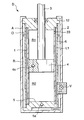
- FIG. 1 is a schematic longitudinal sectional view of a hydraulic shock absorber to which a damping valve according to the present invention is applied.
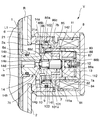
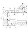
- FIG. 2 is a longitudinal sectional view of a damping valve according to the present invention.
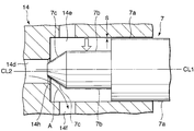
- FIG. 3 is an enlarged side view of the poppet according to the present invention.
- FIG. 4 is a cross-sectional view of the tip of the poppet and the hole.
- FIG. 5 is FIG. 3 shows a second embodiment of the present invention similar to FIG.
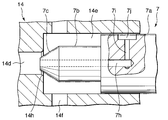
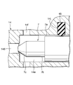
- FIG. 6 is FIG. 3 shows a third embodiment of the invention which is similar to FIG.
- FIG. 7 is an enlarged side view of a poppet according to a fourth embodiment of the present invention.
- FIG. 8 is FIG. 7 is similar to FIG. 7, but shows a fifth embodiment of the present invention.
- FIG. 1 the damping valve V according to the present invention is applied to a double cylinder uniflow type hydraulic shock absorber D.
- the hydraulic shock absorber D includes an outer tube 2 outside the cylinder 1 filled with hydraulic oil.
- a space between the cylinder 1 and the outer tube 2 is defined by an inner tube 6 into an inner hydraulic oil passage L1 and an outer reservoir R.
- the cylinder 1, the inner tube 6, and the outer tube 2 are configured on the same axis.
- the space in the cylinder 1 is defined by an oil chamber R1 on the piston rod 3 side and an oil chamber R2 on the opposite side of the piston rod 3 by a piston 4 fixed to one end of the piston rod 3.
- the piston 4 slides in the cylinder 1 in the axial direction in response to the penetration of the piston rod 3 into the cylinder 1 and the withdrawal from the cylinder 1, in other words, expansion and contraction of the hydraulic shock absorber D.
- the rod guide 12 is fixed to the upper end of the outer tube 2.
- the piston rod 3 protrudes freely from the rod guide 12 to the outside of the cylinder 1 in the axial direction.
- the opening at the upper end of the outer tube 2, the inner tube 6 and the cylinder 1 is closed by a rod guide 12.
- the outer tube 2 is formed in a bottomed cylindrical shape, and the inner tube 6 is erected with a predetermined gap between it and the bottom of the outer tube 2.
- the bottom of the inner tube 6 is closed by the base 5 together with the bottom of the cylinder 1.
- the hydraulic oil is stored in the reservoir R.
- Gas A is sealed above the oil level O of the reservoir R.
- the base 5 is provided with a check valve 5a.
- the check valve 5a allows the hydraulic oil in the reservoir R to flow into the oil chamber R2 without resistance as the oil chamber R2 on the side opposite to the piston rod 3 expands with the extension operation of the hydraulic shock absorber D. Block the flow of hydraulic oil.
- the reservoir R and the check valve 5a always communicate with each other through a gap between the inner tube 6 and the bottom of the outer tube 2.
- the piston 4 is provided with a check valve 4a. While the check valve 4a causes the hydraulic chamber R2 on the side opposite to the piston rod 3 to contract with the contraction operation of the hydraulic shock absorber D, the excess hydraulic oil in the oil chamber R2 flows into the oil chamber R1 without resistance. Blocks the reverse flow of hydraulic fluid.
- the oil chamber R2 on the piston rod 3 side communicates with the hydraulic oil passage L1 inside the inner tube 6 through a through hole 33 formed in the upper part of the cylinder 1.
- the hydraulic shock absorber D includes a damping valve V that connects the hydraulic oil passage L1 inside the inner tube 6 and the reservoir R outside the inner tube 6.
- hydraulic oil flows out from the oil chamber R1 on the piston rod 3 side that contracts when extending to the reservoir via the damping valve V, and generates an extension side damping force based on the flow resistance of the damping valve V.
- hydraulic oil flows into the oil chamber R2 on the piston rod side through the check valve 4a from the oil chamber R2 on the opposite side to the piston rod 3 that contracts when contracted.
- the hydraulic oil corresponding to the intrusion volume of the piston rod 3 into the cylinder 1 is excessive in the cylinder 1.
- This hydraulic oil flows out from the oil chamber R1 to the reservoir R through the damping valve V, and generates a compression side damping force based on the flow resistance of the damping valve V.
- the cross-sectional area of the piston rod 3 and the cross-sectional area of the oil chamber R2 on the opposite side of the piston rod 3 are set to 1: 2, the expansion and contraction operations of the hydraulic shock absorber D are performed from the oil chamber R2 via the damping valve V. Accordingly, the flow rate of the hydraulic oil flowing out to the reservoir R becomes equal, and the hydraulic shock absorber D generates the same damping force for the expansion operation and the contraction operation.
- FIG. 1 Referring to FIG. 2, the damping valve V is housed in the valve case 11 together with the fail-safe valve 10.
- the outer tube 2 has an opening 2a on the side surface.
- a cylindrical socket 21 is fixed to the outer peripheral surface of the outer tube 2 by welding or the like so as to surround the opening 2a.
- a cylindrical valve case 11 is screwed onto the outer periphery of the socket 21.
- a lid 112 is caulked and fixed to the end of the valve case 11.
- the valve case 11 is formed with a flange portion 111a protruding in the center direction on the inner periphery.
- the solenoid 8 is sandwiched between the flange portion 111a and the lid 112.
- the solenoid 8 includes a coil 81 and a bobbin 82 around which the coil 81 is wound.
- the tip of the bobbin 82 is locked to the flange portion 111a.
- the rear end of the bobbin 82 contacts the lid 112.
- a cylindrical first fixed iron core 83 is fitted to the inner periphery of the bobbin 82 with the bottom surface in contact with the lid 112.
- a spacer 84 made of a nonmagnetic material having the same cross section is fitted to the inner periphery of the bobbin 82 continuously from the tip of the first fixed iron core 83. Further, a second fixed iron core 85 made of a magnetic material having the same cross section is connected to the inner periphery of the bobbin 82 continuously from the tip of the spacer 84.
- the tip of the second fixed iron core 85 protrudes from the bobbin 82 in the axial direction.
- An outer movable iron core 86 made of a magnetic material is arranged coaxially with the second fixed iron core 85.
- the outer movable iron core 86 constitutes the valve body of the failsafe valve 10.
- the inner movable iron core 88 is housed inside the first fixed iron core 83.
- a ring-shaped washer 87 made of a nonmagnetic material is interposed between one end of the inner movable iron core 88 and the first fixed iron core 83.
- a concave portion 88 a facing the bottom of the first fixed iron core 83 is formed at the center of the inner movable iron core 88.
- the spring force adjusting screw 12 is screwed into the center of the bottom portion of the first fixed iron core 83 from the axial direction.
- the tip of the spring force adjusting screw 12 enters the recess 88a.
- the spring 13 is interposed between the inner movable iron core 88 and the spring force adjusting screw 12.
- the spring 13 is supported by the spring force adjusting screw 12 and biases the inner movable iron core 88 in a direction away from the bottom of the first fixed iron core 83.
- the spring force adjusting screw 12 cannot be operated.
- the lid 112 is configured to be removable from the valve case 11 such as by screwing the lid 112 to the valve case 11, the spring 112 can be removed by removing the lid 112 from the valve case 11 even after the assembly of the hydraulic shock absorber D is completed.
- the force adjusting screw 12 can be operated.
- the inner tube 6 has a sleeve 6a that opens to the side.
- the end 14b of the valve housing 14 is fitted to the inner periphery of the sleeve 6a.
- An inlet port L communicating with the hydraulic oil passage L1 between the inner tube 6 and the cylinder 1 is formed inside the end portion 14b.
- a seal member 48 is disposed between the sleeve 6 a and the end 14 b of the valve housing 14 so that the working fluid in the hydraulic oil passage L ⁇ b> 1 does not leak to the outside of the inner tube 6.
- valve housing 14 a reduced diameter portion 14d having a small diameter and a valve chamber 14e having a diameter larger than that of the reduced diameter portion 14d are formed coaxially with the inlet port L. Furthermore, a plurality of outlet ports 14f penetrating the valve housing 14 in the radial direction from the valve chamber 14e are formed. A valve seat 14h is formed in a ring shape around the opening of the reduced diameter portion 14d toward the valve chamber 14e.
- the base end 7a of the poppet 7 constituting the valve body of the damping valve V is slidably fitted in the axial direction.
- the base end 7 a of the poppet 7 protrudes from the valve housing 14 in the axial direction and abuts against the inner movable iron core 88.
- the poppet 7 has a tip 7b having a smaller diameter than the base end 7a.
- a conical valve head 7c is formed at the tip of the tip 7b.
- a spring 9 is interposed between the valve seat 14h and the step between the proximal end 7a and the distal end 7b of the poppet 7.
- the spring 9 biases the poppet 7 toward the inner movable iron core 88. Since the spring 9 is arranged in series with the spring 13, when the spring load of the spring 13 is adjusted by the spring force adjusting screw 12, the spring load of the spring 9 is also adjusted at the same time.
- a flange 14a and a large diameter portion 14i are formed over the entire circumference at a position sandwiching the outlet port 14f in the axial direction of the valve housing 14.
- the outer periphery of the flange 14a reaches the inner peripheral surface of the socket 21.
- a cylindrical spacer 101 is fitted inside the socket 21.
- An inward flange portion 101a is formed on the end surface of the spacer 101 opposite to the flange 14a.
- the flange portion 101 a abuts on the flange portion 111 a of the valve case 11.
- the solenoid 8 abuts on the end of the bobbin 82 in the axial direction.
- the flange 14 a is sandwiched between the flange portion 111 a and the step 21 a inside the socket 21 via the spacer 101 by screwing the valve case 11 to the outer periphery of the socket 21.
- a seal member 102 is interposed between the spacer 101 and the socket 21.
- the second fixed iron core 85 protruding in the axial direction from the bobbin 82 is fitted to the inner periphery of the flange portion 101a.
- the outer movable iron core 86 corresponding to the valve body of the failsafe valve 10 has a thick cylindrical shape and is fitted to the outer periphery of the large diameter portion 14i of the valve housing 14.
- the outer movable iron core 86 includes a flange 86a parallel to the flange 14a of the valve housing 14, and an annular protrusion 86b protruding from the inner peripheral portion toward the flange 14a.
- a spring 103 that biases the outer movable iron core 86 toward the flange 14a is interposed between the flange 86a and the flange portion 101a of the spacer 101. In the state where the solenoid 8 is not excited, the outer movable iron core 86 is held at the advanced position where the annular protrusion 86b is in contact with the flange 14a of the valve housing 14.
- the outer movable iron core 86 is formed with a plurality of orifices 86c that penetrate the wall surface and communicate the inner side and the outer side.
- the outer movable iron core 86 further includes a valve housing 14, an outer movable iron core 86, and a poppet 7 on the inner side of a continuous cylinder formed by the first fixed iron core 83, the spacer 84, and the second fixed iron core 85. Is formed, and a through hole 86d is formed to connect the orifice 86c.
- the communication hole 14g is formed in the flange 14a.
- the inlet port L communicates with the reservoir R through the reduced diameter portion 14d, the valve chamber 14e, the outlet port 14f, the inner side of the spacer 101 in which the outer movable iron core 86 is accommodated, the communication hole 14g, and the opening 2a of the outer tube 2. To do.
- a cylindrical stopper 142 made of a non-magnetic material is mounted on the outer periphery of the valve housing 14.
- the inner movable iron core 88 is in contact with the stopper 142, so that further axial displacement is restricted.
- the washer 87 and the stopper 142 are made of a synthetic resin material, it is possible to suppress the occurrence of impact and noise when the inner movable iron core 88 collides with the washer 87 and the stopper 142.
- the inner movable iron core 88 is formed in such a size that the outer periphery of the tip slightly overlaps with the second fixed iron core 85 in a state where it is in contact with the washer 87.
- the inner movable iron core 88 is also formed with a through hole 88b for equalizing hydraulic oil pressure acting on both end faces in the axial direction.
- the magnetic path formed by the illustrated solenoid 8 extends from the second fixed iron core 85 to the valve case 11 through the outer movable iron core 86, the valve housing 14, and the socket 21.
- the outer movable iron core 86 at the forward position is attracted to the second fixed iron core 85 against the spring 103 and comes into contact with the second fixed iron core 85, so that the annular protrusion 86b and the flange 14a are in contact with each other. A flow path is formed between them.
- the damping valve V is lifted from the valve seat 14h, and the inlet port L and the valve chamber 14e are communicated with each other through the annular gap between the poppet 7 and the valve seat 14h.
- the outer movable iron core 86 which is a fail-safe valve, is held at a forward position where the annular protrusion 86b is in contact with the flange 14a, and communicates with the outlet port 14f and the clearance between the annular protrusion 86b and the flange 14a from the valve chamber 14e.
- the hydraulic oil flow path up to 14 g is closed.
- the damping valve V enters a closed state in which the valve head 7c is seated on the valve seat 14h.
- the fail-safe valve 10 is in an open state in which a flow path is formed between the annular protrusion 86b and the flange 14a by the second fixed iron core 85 attracting the outer movable iron core 86.
- the poppet 7 is restricted from displacement in the radial direction and swinging with respect to the central axis by fitting the base end 7a to the inner periphery of the valve chamber 14e.
- the poppet 7 is held on the central axis when fitted. However, if there is a manufacturing error in either the base end 7a and the valve chamber 14e, or the operation of the hydraulic shock absorber D accumulates, the sliding contact surface between the base end 7a of the poppet 7 and the inner periphery of the valve chamber 14e is worn.
- This invention provides a biasing mechanism that biases the poppet 7 in a direction perpendicular to the central axis in order to prevent the poppet 7 from vibrating.
- FIG. 3 a sliding gap S is set in advance between the inner peripheral surface of the valve chamber 14 e and the base end 7 a of the poppet 7.
- FIG. Illustration of the spring 9 shown in Fig. 2 is omitted.
- FIG. In FIG. 5-8, the illustration of the spring 9 is omitted for the same reason.
- FIG. 4 Referring to FIG. 4, by this setting, the valve head 7c of the poppet 7 is held at a position eccentric to the upper side in the drawing as viewed from the direction of the central axis CL2 of the reduced diameter portion 14d. In other words, the flow cross section of the hydraulic oil flowing into the valve chamber 14e from the reduced diameter portion 14d becomes the widest below the valve head 7c.
- FIG. 3 the hydraulic oil that has flowed into the valve chamber 14e flows out of the valve housing 14 from the outlet port 14f.
- the hydraulic oil that extends from the reduced diameter portion 14d through the valve chamber 14e to the outlet port 14f circulates more below the valve head 7c having a wide flow section. That is, the flow velocity in the region below the valve head 7c in the figure is faster than the region above the valve head 7c, and the hydraulic oil pressure decreases accordingly. Due to the difference in pressure, a downward force in the figure acts on the poppet 7.
- the poppet 7 In response to this pressing force, the poppet 7 is displaced downward within the range allowed by the sliding gap S as shown by a two-dot chain line in the figure, and the base end 7a of the poppet 7 is brought into contact with the lower wall surface of the valve chamber 14e in the figure. Pressed.
- This pressing force acts as a force that prevents the base end 7a of the poppet 7 from moving away from the lower wall surface of the valve chamber 14e even when a force that induces vibration acts on the poppet 7.
- the vibration of the poppet 7 can be suppressed by the vibration preventing mechanism described above.
- the reduced diameter portion 14d is formed at a position eccentric to the lower side with respect to the valve chamber 14e.
- the eccentric direction is not necessarily downward, but it is desirable to suppress the vibration of the poppet 7 that the input direction of vibration and the pressing direction of the poppet 7 against the wall surface of the valve chamber 14e overlap on the same plane.
- the pressing force acts on the poppet 7 in either the upper or lower direction, so that a particularly great effect can be obtained with respect to preventing the poppet 7 from vibrating.
- FIG. 5 a second embodiment of the present invention regarding the vibration preventing mechanism of the poppet 7 will be described.
- a tapered surface 7d is formed on the upper portion of the valve head 7c shown in the figure, while a tapered surface 7e having the same inclination as the tapered surface 7d and a tapered surface 7f inclined more gently than the tapered surface 7d are formed on the lower portion of the valve head 7c shown in the drawing.
- the gentle inclination means that the angle intersecting with the central axis CL1 is small. That is, the tapered surface at the tip of the valve head 7c has the same inclination over 360 degrees. However, when the distance from the tip is more than a certain distance, the tapered surface 7e at the bottom of the valve head 7c shown in FIG. change.
- the cross-sectional area of the flow of hydraulic oil from the reduced diameter portion 14d indicated by the arrow A in the drawing to the lower outlet port 14f in the drawing is the flow of hydraulic oil from the reduced diameter portion 14d to the upper outlet port 14f in the drawing.
- the cross-sectional area becomes larger.
- the downward force corresponding to the flow velocity difference acts on the poppet 7 as in the first embodiment, and the poppet 7 is moved to the lower side of the valve chamber 14e as shown by the two-dot chain line in the drawing. Press against the wall. As a result, the vibration of the poppet 7 can be suppressed.
- tapered surface 7f Various variations are possible for the tapered surface 7f.
- FIG. 6 a third embodiment of the present invention regarding the vibration preventing mechanism of the poppet 7 will be described.
- a hole 7h is formed in the poppet 7 from the valve head 7c to the inside of the base end 7a.
- the end of the hole 7h is connected to a lateral hole 7i formed in the base end 7a.
- the lateral hole 7i opens to the outer periphery of the base end 7a via a pressure action chamber 7j formed at the upper part of the base end 7a in the figure.
- the pressure of the hydraulic oil flowing into the valve chamber 14e from the reduced diameter portion 14d acts on the wall surface of the valve chamber 14e via the hole portion 7h, the lateral hole 7i, and the pressure action chamber 7j.
- This pressure acting between the pressure acting chamber 7j and the wall surface of the valve chamber 14e exerts a downward force on the poppet 7 so that the poppet 7 is moved to the bottom of the valve chamber 14e as shown by a two-dot chain line in the figure. Press against the side wall. As a result, the vibration of the poppet 7 can be suppressed.
- FIG. 7 a fourth embodiment of the present invention in which an elastic force is loaded on the poppet 7 in advance will be described.
- a hole 14j facing the valve chamber 14e is formed in the valve housing 14 in a direction perpendicular to the central axis of the poppet 7, and the base end 7a of the poppet 7 is connected to the valve by a rubber member 45 accommodated in the hole 14j. It biases toward the wall surface on the opposite side of the chamber 14e.
- a through hole reaching from the outside of the valve housing 14 to the inside of the valve chamber 14 e is formed, and after inserting the rubber member 45 into the through hole from the outside of the valve housing 14, the through hole is plugged from the outside of the valve housing 14. It is realized by doing.
- the plugged through hole functions as the hole 14j.
- the elastic force of the rubber member 45 is always applied to the poppet 7 in the transverse direction, and the poppet 7 is pressed against the lower wall surface of the valve chamber 14e. As a result, the vibration of the poppet 7 can be suppressed. According to this embodiment, the invention can be carried out without processing the poppet 7.
- FIG. 8 a fifth embodiment of the present invention in which an elastic force is applied to the poppet 7 in advance will be described.
- a hole 14j is formed in the valve chamber 14e in a direction perpendicular to the central axis of the poppet 7 as in the fourth embodiment.
- a coil spring 46 is housed in the hole 14j instead of the rubber member 45 of the fourth embodiment, and a shoe 47 that is in sliding contact with the base end 7a of the poppet 7 is supported by the coil spring 46.
- a through hole reaching from the outside of the valve housing 14 to the inside of the valve chamber 14e is formed in advance. After inserting a poppet into the valve chamber 14 e and sequentially inserting the shoe 47 and the coil spring 46 from the outside of the valve housing 14 into the through hole, the through hole is plugged from the outside of the valve housing 14. The plugged through hole functions as the hole 14j.
- the elastic force by the coil spring 46 always exerts a downward force on the poppet 7 via the shoe 47, and presses the poppet 7 against the lower wall surface of the valve chamber 14e. As a result, the vibration of the poppet 7 can be suppressed. Also in this embodiment, it is not necessary to process the poppet 7.
- the vibration input direction and the pressing direction of the poppet 7 against the wall surface of the valve chamber 14e overlap on the same plane in order to enhance the vibration suppressing effect of the poppet 7. Is desirable.
- the hole 14j for accommodating the rubber member 45 or the coil spring 46 above or below the valve chamber 14e as shown in the figure, a particularly great effect can be obtained with regard to preventing the poppet 7 from vibrating. can get.
- the hydraulic shock absorber D expands and contracts in the vertical direction in the figure. Since the central axis of the poppet 7 is orthogonal to the central axis of the hydraulic shock absorber D, vibrations absorbed by the hydraulic shock absorber D cause vibrations in the transverse direction with respect to the poppet 7.
- the hydraulic oil passes through the single damping valve V in both the expansion stroke and the contraction stroke, and the damping valve V is frequently used. Therefore, the vibration of the poppet 7 is likely to occur accordingly.
- the poppet 7 is prevented from vibrating by applying a pressing force to the wall surface of the valve chamber 14e. Therefore, a favorable effect is obtained in suppressing noise generation of the hydraulic shock absorber D and stabilizing the generated damping force.
- the present invention is not limited to the driving structure of the poppet 7.
- a fluid such as an aqueous solution other than the working oil can be used as the working fluid.
- the damping valve according to the present invention brings about a preferable effect in preventing the generation of noise and the variation in damping force of the vehicle fluid pressure buffer.
Landscapes
- Engineering & Computer Science (AREA)
- General Engineering & Computer Science (AREA)
- Mechanical Engineering (AREA)
- Physics & Mathematics (AREA)
- Electromagnetism (AREA)
- Magnetically Actuated Valves (AREA)
- Details Of Valves (AREA)
- Fluid-Damping Devices (AREA)
Abstract
減衰弁は流体の通路を構成する通孔と、通孔周囲のバルブシートに着座する、中心軸を有するポペットとを備える。ポペットはハウジングに中心軸方向に摺動自由に収装される。ポペットを中心軸と直角方向に付勢する付勢メカニズムにより、ポペットをハウジングの一方の壁面に押し付けることで、ポペットの振動を抑制する。
Description
この発明は、ポペット型のバルブボディを用いた減衰弁に関する。
日本国特許庁が2009年に発行したJP2009-222136Aは、ポペット型のバルブボディを備えた油圧緩衝器の減衰弁を開示している。
油圧緩衝器はシリンダの外側にアウタチューブを備え、シリンダの外側のアウタチューブ内に作動油のリザーバを備えている。シリンダにはピストンロッドに結合したピストンが収装される。シリンダの内側にはピストンにより、ピストンロッド側の油室と、ピストンロッドと反対側の油室とが形成される。
減衰弁はピストンロッド側の油室からリザーバへ作動油を流出させる作動油通路に設けられている。
バルブボディを構成するポペットは、励磁されたソレノイドの磁力により、先端を作動油通路に形成された孔部の周りのリング状のバルブシートに着座することで作動油通路を閉鎖する。ソレノイドが励磁されていない状態では、ポペットはバルブシートからリフトし、バルブシートとポペットとの間の環状隙間を介して作動油を流通させる。
ソレノイドが励磁された状態で、ポペットに加わる作動油通路の圧力が上昇すると、作動油通路の圧力に応じてポペットの先端がソレノイドの磁力に抗してバルブシートからリフトする。その結果生じるバルブシートとポペットの先端との環状隙間を介して、作動油がポペットの先端の周りに形成されたバルブ室に流入する。バルブ室にはポペットの先端に対して直角方向に作動油を流出させる出口ポートが開口し、作動油通路からバルブ室に流入した作動油は出口ポートを通ってリザーバへと流出する。
ポペットを軸方向に摺動自由に支持するために、ポペットはポペットの先端より大径に形成され、バルブハウジングに摺動自由に嵌合する基端を備える。
ポペットがリフトした状態では、バルブハウジング内に孔部からポペットの先端を廻り込むようにして出口ポートへ向かう作動油の流れが形成される。
部品の製造誤差や爾後の磨耗により、ポペットの基端とハウジングとの摺動隙間が広がると、この作動流体の流れが、ポペットにハウジング内でラジアル方向の振動を誘起することがある。
特に、油圧緩衝器を車両の車体と車軸との間に介装する場合には、油圧緩衝器が路面振動を吸収する際に、油圧緩衝器内の油室の圧力が激しく変化する。こうした状況でポペットが振動すると、騒音の発生要因となったり、発生減衰力に好ましくない影響を与える可能性がある。
この発明の目的は、したがって、バルブボディにポペットを用いた減衰弁において、ポペットの振動を抑制することである。
以上の目的を達成するために、この発明による減衰弁は、流体の通路を構成する通孔と、通孔周囲のバルブシートに着座する、中心軸を有するポペットとを備えている。ポペットはハウジングに中心軸方向に摺動自由に収装される。減衰弁はまた、ポペットを中心軸と直角方向に付勢する付勢メカニズムを備えている。
この発明の詳細並びに他の特徴や利点は、明細書の以下の記載の中で説明されるとともに、添付された図面に示される。
FIG.1を参照すると、この発明による減衰弁Vは、複筒ユニフロー型の油圧緩衝器Dに適用される。
油圧緩衝器Dは、作動油を充填したシリンダ1の外にアウタチューブ2を備える。シリンダ1とアウタチューブ2との間のスペースはインナチューブ6により内側の作動油通路L1と外側のリザーバRとに画成される。シリンダ1、インナチューブ6、及びアウタチューブ2は同軸上に構成される。
シリンダ1内のスペースはピストンロッド3の一端に固定されたピストン4により、ピストンロッド3側の油室R1と、ピストンロッド3と反対側の油室R2とに画成される。ピストン4はピストンロッド3のシリンダ1に対する侵入とシリンダ1からの退出、言い換えれば油圧緩衝器Dの伸縮、に応じてシリンダ1内を軸方向に摺動する。
アウタチューブ2の上端にはロッドガイド12が固定される。ピストンロッド3はロッドガイド12からシリンダ1の軸方向外側へ摺動自由に突出する。アウタチューブ2とインナチューブ6とシリンダ1の上端の開口部はロッドガイド12により閉鎖される。
アウタチューブ2は有底の筒状に形成され、インナチューブ6はアウタチューブ2の底部との間に所定の隙間をあけて立設される。インナチューブ6の底部はシリンダ1の底部とともにベース5によって閉鎖される。
リザーバRには作動油が貯留される。リザーバRの油面Oの上方にはガスAが封入される。
ベース5にはチェック弁5aが設けられる。チェック弁5aは油圧緩衝器Dの伸長動作に伴ってピストンロッド3と反対側の油室R2が拡大するのに応じて、リザーバRの作動油を抵抗なく油室R2に流入させる一方、逆方向の作動油の流通を阻止する。なお、リザーバRとチェック弁5aは、インナチューブ6とアウタチューブ2の底部との隙間を介して常時連通する。
ピストン4にはチェック弁4aが設けられる。チェック弁4aは油圧緩衝器Dの収縮動作に伴ってピストンロッド3と反対側の油室R2が縮小するのに応じて、油室R2の余剰作動油を抵抗なく油室R1に流出させる一方、逆向きの作動油の流通を阻止する。
ピストンロッド3側の油室R2はシリンダ1の上部に形成された通孔33を介してインナチューブ6の内側の作動油通路L1に連通する。
油圧緩衝器Dは、インナチューブ6の内側の作動油通路L1とインナチューブ6の外側のリザーバRとを接続する減衰弁Vを備える。
この油圧緩衝器Dは伸長時には縮小するピストンロッド3側の油室R1から減衰弁Vを介して作動油がリザーバへと流出し、減衰弁Vの流通抵抗に基づく伸側減衰力を発生させる。油圧緩衝器Dは収縮時には縮小するピストンロッド3と反対側の油室R2からチェック弁4aを介して作動油がピストンロッド側の油室R2に流入する。しかしながら、シリンダ1内ではピストンロッド3のシリンダ1への侵入体積相当の作動油が余剰となる。この作動油は油室R1から減衰弁Vを介してリザーバRへ流出し、減衰弁Vの流通抵抗に基づく縮側減衰力を発生させる。
つまり、油圧緩衝器Dの伸長動作と収縮動作のいずれにおいても、シリンダ1内の作動油は減衰弁Vを介してリザーバRへと流出し、減衰弁Vが作動油の流通流量に応じて減衰力を発生させる。
ピストンロッド3の断面積とピストンロッド3と反対側の油室R2の断面積とを1対2に設定すれば、油圧緩衝器Dの伸長動作と収縮動作において油室R2から減衰弁Vを介してリザーバRに流出する作動油流量が等しくなり、油圧緩衝器Dは伸長動作と収縮動作に対して等しい減衰力を発生する。
FIG.2を参照すると、減衰弁Vはフェールセーフ弁10とともにバルブケース11に収装される。
アウタチューブ2は側面に開口部2aを有する。アウタチューブ2の外周面には開口部2aを囲むように円筒形状のソケット21が溶接などで固定される。ソケット21の外周に円筒形状のバルブケース11が螺合する。バルブケース11の端部には蓋112がかしめ固定される。
バルブケース11は内周に中心方向に突出するフランジ部111aが形成される。ソレノイド8がフランジ部111aと蓋112に挟持される。
ソレノイド8は、コイル81と、コイル81を巻き回したボビン82とを備える。ボビン82の先端はフランジ部111aに係止される。ボビン82の後端は蓋112に当接する。ボビン82の内周には円筒形状の第1固定鉄芯83が底面を蓋112に当接した状態で嵌合する。
ボビン82の内周には、第1固定鉄芯83の先端に連続して、同一断面の非磁性材で構成されたスペーサ84が嵌合する。さらに、スペーサ84の先端に連続して同一断面の磁性材で構成された第2固定鉄芯85がボビン82の内周に勘合する。
第2固定鉄芯85の先端はボビン82から軸方向に突出する。第2固定鉄芯85と同軸上に磁性材で構成された外側可動鉄芯86が配置される。外側可動鉄芯86はフェールセーフ弁10のバルボディを構成する。
第1固定鉄芯83の内側には内側可動鉄芯88が収装される。内側可動鉄芯88の一端と第1固定鉄芯83との間には非磁性材で構成されたリング状のワッシャ87が介装される。内側可動鉄芯88の中心には第1固定鉄芯83の底部を向いた凹部88aが形成される。
第1固定鉄芯83の底部の中心には軸方向からばね力調整ねじ12が螺合する。ばね力調整ねじ12の先端は凹部88a内に侵入する。凹部88a内において、内側可動鉄芯88とばね力調整ねじ12との間にスプリング13が介装される。スプリング13はばね力調整ねじ12に支持され、内側可動鉄芯88を第1固定鉄芯83の底部から離間する方向に付勢する。
この構造のもとでは、バルブケース11に蓋112がかしめ固定された後は、ばね力調整ねじ12の操作を行うことはできない。例えば蓋112をバルブケース11に螺合させるなど、蓋112をバルブケース11から取り外し可能に構成すれば、油圧緩衝器Dの組み立てが完成した後も、蓋112をバルブケース11から取り外すことでばね力調整ねじ12の操作が可能になる。
インナチューブ6は側方に開口するスリーブ6aを有する。スリーブ6aの内周にバルブハウジング14の端部14bが嵌合する。端部14bの内側にはインナチューブ6とシリンダ1の間の作動油通路L1に連通する入口ポートLが形成される。作動油通路L1の作動流体がインナチューブ6の外側に漏出しないように、スリーブ6aとバルブハウジング14の端部14bとの間にシール部材48が配置される。
バルブハウジング14内には入口ポートLに連続して同軸上に小径の縮径部14dと、縮径部14dより径の大きなバルブ室14eとが形成される。さらに、バルブ室14eからラジアル方向にバルブハウジング14を貫通する複数の出口ポート14fが形成される。縮径部14dのバルブ室14eに向けた開口部の周囲にはバルブシート14hがリング状に形成される。
バルブ室14eには減衰弁Vのバルブボディを構成するポペット7の基端7aが軸方向に摺動自由に嵌合する。ポペット7の基端7aはバルブハウジング14から軸方向に突出し、内側可動鉄芯88に当接する。ポペット7は基端7aより小径の先端7bを有する。先端7bの先端には円錐形状のバルブヘッド7cが形成される。バルブヘッド7cがバルブシート14hに着座することで、入口ポートLとバルブ室14eとの連通が遮断される。
バルブ室14e内において、バルブシート14hとポペット7の基端7aと先端7bとの段差との間にはスプリング9が介装される。スプリング9はポペット7を内側可動鉄芯88に向けて付勢する。なお、スプリング9はスプリング13と直列に配置されているため、ばね力調整ねじ12によりスプリング13のばね荷重を調整する場合には、スプリング9のばね荷重も同時に調整される。
バルブハウジング14の外周には、バルブハウジング14の軸方向に関して出口ポート14fを挟む位置にフランジ14aと大径部14iが全周に渡って形成される。
フランジ14aの外周はソケット21の内周面に達する。ソケット21の内側には円筒形状のスペーサ101が嵌合する。スペーサ101にはフランジ14aと反対側の端面には内向きのフランジ部101aが形成される。フランジ部101aはバルブケース11のフランジ部111aに当接する。また、ソレノイド8のボビン82の軸方向の端部に当接する。
フランジ14aは、バルブケース11をソケット21の外周に螺合させることで、フランジ部111aとソケット21の内側の段差21aとの間にスペーサ101を介して挟持される。スペーサ101の内側から外側への作動油のリークを防止するために、スペーサ101とソケット21との間にはシール部材102が介装される。
フランジ部101aの内周には、ボビン82から軸方向に突出した第2固定鉄芯85が嵌合する。
フェールセーフ弁10のバルブボディに相当する外側可動鉄芯86は肉厚の筒状をなし、バルブハウジング14の大径部14iの外周に嵌合する。外側可動鉄芯86はバルブハウジング14のフランジ14aと平行なフランジ86aと、内周部からフランジ14aに向けて突出する環状突起86bとを備える。フランジ86aとスペーサ101のフランジ部101aとの間には外側可動鉄芯86をフランジ14aに向けて付勢するスプリング103が介装される。ソレノイド8が励磁されない状態では、外側可動鉄芯86は環状突起86bをバルブハウジング14のフランジ14aに当接した前進位置に保持される。
外側可動鉄芯86には壁面を貫通して、内側と外側とを連通する複数のオリフィス86cが形成される。外側可動鉄芯86にはさらに、第1の固定鉄芯83、スペーサ84、及び第2の固定鉄芯85が構成する連続した円筒の内側にバルブハウジング14と外側可動鉄芯86とポペット7とが画成するスペースと、オリフィス86cと、を接続する通孔86dが形成される。
フランジ14aには連通孔14gが形成される。入口ポートLは縮径部14d,バルブ室14e,出口ポート14f,外側可動鉄芯86が収装されるスペーサ101の内側、連通孔14g、アウタチューブ2の開口部2aを介してリザーバRに連通する。
大径部14iと内側可動鉄芯88の間において、バルブハウジング14の外周には非磁性材で構成された筒状のストッパ142が装着される。内側可動鉄芯88はストッパ142に当接することで、それ以上の軸方向変位を規制される。なお、好ましくはワッシャ87とストッパ142を合成樹脂材料で構成すれば、内側可動鉄芯88がワッシャ87やストッパ142に衝突した場合の衝撃や騒音の発生を抑制することができる。
内側可動鉄芯88は、ワッシャ87に当接した状態で先端外周が第2の固定鉄芯85と若干重なる寸法に形成される。内側可動鉄芯88にはまた、軸方向の両端面に作用する作動油圧力を等しくするための貫通孔88bが形成される。
ソレノイド8が励磁されると、第1の固定鉄芯83,内側可動鉄芯88、第2の固定鉄芯85を通る磁路が形成される。このとき、非磁性材のスペーサ84の先端に、外周の軸方向長さに対して内周の軸方向長さが短くなるようにテーパ面を形成し、これに接合する第2の固定鉄芯85の基端にも同様のテーパ面を形成することで、励磁されたソレノイド8の磁束が第1の固定鉄芯83と第2の固定鉄芯85の内周寄りに集中し、内側可動鉄芯88を介した磁路が構成されやすくなる。このような磁路の形成により、内側可動鉄芯88はポペット7を介して作用するスプリング9の反発力に抗して第2の固定鉄芯85に引き寄せられる。
第2の固定鉄芯85に引き寄せられた内側可動鉄芯88が軸方向に変位するのに伴い、内側可動鉄芯88に基端を当接するポペット7は内側可動鉄芯88によりバルブシート14hに向けて駆動され、バルブヘッド7cをバルブシート14hに着座させる。
一方、例示されたソレノイド8が形成する磁路は第2の固定鉄芯85からさらに外側可動鉄芯86,バルブハウジング14,ソケット21を通ってバルブケース11に至る。その結果、前進位置の外側可動鉄芯86はスプリング103に抗して第2の固定鉄芯85に引き寄せられ、第2の固定鉄芯85に当接することで、環状突起86bとフランジ14aとの間に流路を形成する。
つまり、ソレノイド8が非励磁状態にある場合には、減衰弁Vはバルブシート14hからリフトし、ポペット7とバルブシート14hとの環状隙間を介して入口ポートLとバルブ室14eとを連通している。フェールセーフ弁である外側可動鉄芯86は環状突起86bをフランジ14aに当接させた前進位置に保持され、バルブ室14eから出口ポート14f及び環状突起86bとフランジ14aとの隙間を介して連通孔14gに至る作動油の流路を閉鎖している。この状態では、入口ポートLから縮径部14dを介してバルブ室14eへ比較的容易に作動油が流入する。一方、バルブ室14eの作動油はオリフィス86cを介して連通孔14gへ流出する。この流路構成のもとではもっとも流通断面の小さいオリフィス86cが主として減衰力を発生させる。
何らかのトラブルによりソレノイド8への励磁電流の供給が停止した場合は、減衰弁Vとフェールセーフ弁10はこの位置に保持される。この状態をフェール状態と称する。フェール状態において減衰弁Vが十分な減衰力を発生できない場合でも、このようにして減衰弁Vと直列に配置されたフェールセーフ弁19により最小必要限の減衰力を発生させることができる。
一方、ソレノイド8が励磁されると、減衰弁Vはバルブヘッド7cをバルブシート14hに着座させた閉鎖状態となる。フェールセーフ弁10は第2の固定鉄芯85が外側可動鉄芯86を引き寄せることで、環状突起86bとフランジ14aとの間に流路を構成した開放状態となる。
この状態では、入口ポートLからバルブ室14eに流入する作動油は縮径部14dの作動油圧力でポペット7をバルブシート14hからリフトさせなければならない。この時のクラッキング圧はソレノイド8の励磁電流により変化する。また、ポペット7のリフトした後の減衰弁Vの発生減衰力もソレノイド8の励磁電流に応じて変化する。
ところで、減衰弁Vにおいて、ポペット7は基端7aをバルブ室14eの内周に嵌合させることで、ラジアル方向の変位や中心軸に対する揺動を規制されている。
縮径部14dからバルブ室14eを介して出口ポート14fへと流出する作動油は、ポペット7に軸方向以外の力を及ぼすが、バルブ室14eの内周に基端7aが適正な摺動隙間のもとで嵌合している場合には、ポペット7は中心軸上に保持される。しかし、基端7aとバルブ室14eのいずれかに製造誤差がある場合、あるいは油圧緩衝器Dの動作の蓄積によりポペット7の基端7aとバルブ室14eの内周との摺接面が摩耗した場合には、縮径部14dからバルブ室14eを介して出口ポート14fへと流出する作動油がポペット7に及ぼす軸方向以外の力が、ポペット7に振動を誘起する。入口ポートLの圧力が頻繁に変化するような油圧緩衝器Dの動作状況では、ポペット7のこの振動により油圧緩衝器Dが騒音を発することがある。
この発明はポペット7の振動を防止するために、ポペット7を中心軸と直交する向きに付勢する付勢メカニズムを提供する。
FIG.3を参照すると、バルブ室14eの内周面とポペット7の基端7aとの間にはあらかじめ摺動隙間Sが設定されるものとする。なお、この図では、バルブ室14e内の作動油の流れを説明するために、FIG.2に示したスプリング9の図示が省略されている。FIGS.5-8においても同じ理由でスプリング9の図示が省略されている。
ポペット7とバルブ室14eとが同一の中心軸CL1上に位置した状態で、縮径部14dの中心軸CL2が図の若干下方に来るようにあらかじめ縮径部14dの形成位置を図の下方へずらして設定する。
FIG.4を参照すると、この設定により、ポペット7のバルブヘッド7cは、縮径部14dの中心軸CL2方向から眺めた状態で図の上方へと偏心した位置に保持される。言い換えれば縮径部14dからバルブ室14eに流入する作動油の流通断面はバルブヘッド7cの下方において最も広くなる。
再びFIG.3を参照すると、バルブ室14eに流入した作動油は出口ポート14fからバルブハウジング14の外側へ流出する。縮径部14dからバルブ室14eを通って出口ポート14fに至る作動油は、図の矢印Aに示すように、流通断面の広いバルブヘッド7cの下方をより多く流通する。つまり、図のバルブヘッド7cの下方の領域がバルブヘッド7cの上方の領域より流速が早くなり、その分作動油圧力が低下する。この圧力の相違でポペット7には図の下向きの力が作用する。
この押し付け力を受けてポペット7は図の2点鎖線に示すように摺動隙間Sが許容する範囲で下方へと変位し、ポペット7の基端7aがバルブ室14eの図の下方の壁面に押し付けられる。この押し付け力は、ポペット7に振動を誘起するような力が作用した場合でも、ポペット7の基端7aがバルブ室14eの図の下側の壁面から離間するのを阻止する力として働く。以上の振動防止メカニズムによりポペット7の振動を抑制することができる。
FIGS.3と4では、バルブ室14eに対して縮径部14dを下方へ偏心させた位置に形成している。偏心方向は必ずしも下方でなくても良いが振動の入力方向とバルブ室14eの壁面へのポペット7の押し付け方向とが同一面上で重なることが、ポペット7の振動を抑制するうえで望ましい。つまり、この実施例の場合には、ポペット7に対して上下いずれかの方向に押し付け力が作用することでポペット7の振動防止に関して特に大きな効果が得られる。
FIG.5を参照して、ポペット7の振動防止メカニズムについてのこの発明の第2の実施例を説明する。
この実施例では、縮径部14dに対してバルブヘッド7cを偏心させる代わりに、バルブヘッド7cの形状を変化させることで同じ作用を得る。
図に示すバルブヘッド7cの上部にはテーパ面7dを形成する一方、図に示すバルブヘッド7cの下部にはテーパ面7dと同一傾斜のテーパ面7eと、テーパ面7dより緩傾斜のテーパ面7fとを形成する。ここで、緩傾斜とは中心軸CL1と交わる角度が小さいことを意味する。すなわち、バルブヘッド7cの先端においてはテーパ面は360度に渡って同一傾斜であるが、先端から一定距離以上遠ざかると、図のバルブヘッド7cの下部のテーパ面7eは傾斜の緩いテーパ面7fに変わる。
その結果、図の矢印Aに示す縮径部14dから図の下方の出口ポート14fに至る作動油の流れの断面積は、縮径部14dから図の上方の出口ポート14fに至る作動油の流れの断面積より大きくなる。
この場合も、第1の実施例と同様にポペット7に流速差に応じた図の下向きの力が作用し、図の2点鎖線に示すようにポペット7をバルブ室14eの図の下側の壁面に押し付ける。その結果、ポペット7の振動を抑制することができる。
テーパ面7fについては、さまざまなバリエーションが可能である。例えば図の1点鎖線に示すように先端7bと基端7aとの段差に至る緩やかなテーパ面7gをテーパ面7fの代わりに用いることも可能である。
FIG.6を参照して、ポペット7の振動防止メカニズムについてのこの発明の第3の実施例を説明する。
この実施例において、ポペット7にバルブヘッド7cから基端7aの内側に至る孔部7hを形成する。孔部7hの末端には基端7aに形成された横孔7iに接続する。横孔7iは図の基端7aの上部に形成された圧力作用室7jを介して基端7aの外周に開口する。
この実施例においては、縮径部14dからバルブ室14eに流入する作動油の圧力が孔部7h、横孔7i、及び圧力作用室7jを介してバルブ室14eの壁面に作用する。圧力作用室7jとバルブ室14eの壁面との間に作用するこの圧力がポペット7に図の下向きの力を及ぼして、図の2点鎖線に示すようにポペット7をバルブ室14eの図の下側の壁面に押し付ける。その結果、ポペット7の振動を抑制することができる。
FIG.7を参照して、ポペット7にあらかじめ弾性力を負荷するようにした、この発明の第4の実施例を説明する。
この実施例では、バルブハウジング14に、ポペット7の中心軸と直交する向きにバルブ室14eに臨む穴14jを形成し、穴14jに収装されたゴム部材45によりポペット7の基端7aをバルブ室14eの反対側の壁面に向けて付勢する。
この構成は、バルブハウジング14の外側からバルブ室14eの内側に達する貫通孔を形成し、バルブハウジング14の外側からゴム部材45を貫通孔に挿入した後に、バルブハウジング14の外側から貫通孔をプラグすることで実現する。プラグされた貫通孔が穴14jとして機能する。
この実施例によれば、ゴム部材45の弾性力がポペット7に横断方向に常に負荷され、ポペット7はバルブ室14eの図の下側の壁面に押し付けられる。その結果、ポペット7の振動を抑制することができる。この実施例によれば、ポペット7に加工を加えずに発明を実施できる。
FIG.8を参照して、ポペット7にあらかじめ弾性力を負荷するようにした、この発明の第5の実施例を説明する。
この実施例は、第4の実施例と同様にバルブ室14e内にポペット7の中心軸と直交する向きに穴14jを形成する。穴14jには第4の実施例のゴム部材45に代えてコイルスプリング46を収装し、ポペット7の基端7aに摺接するシュー47をコイルスプリング46で支持する。
この実施形態においても第4の実施例と同様に、あらかじめバルブハウジング14の外側からバルブ室14eの内側に達する貫通孔を形成しておく。バルブ室14eにポペットを挿入し、バルブハウジング14の外側からシュー47とコイルスプリング46とを順次を貫通孔に挿入した後に、バルブハウジング14の外側から貫通孔をプラグする。プラグされた貫通孔が穴14jとして機能する。
この実施例によっても、コイルスプリング46による弾性力がシュー47を介してポペット7に図の下向きの力を常に及ぼし、ポペット7をバルブ室14eの図の下側の壁面に押し付ける。その結果、ポペット7の振動を抑制することができる。この実施例おいても、ポペット7に加工を加える必要はない。
第4の実施例並びに第5の実施例においては、振動の入力方向とバルブ室14eの壁面へのポペット7の押し付け方向とが同一面上で重なることが、ポペット7の振動抑制効果を高めるうえで望ましい。つまり、ゴム部材45またはコイルスプリング46を収装する穴14jを、図に示すようにバルブ室14eの上方に形成するか、あるいは下方に形成することで、ポペット7の振動防止に関して特に大きな効果が得られる。
以上の各実施例において、油圧緩衝器Dは図の上下方向に伸縮する。ポペット7の中心軸は油圧緩衝器Dの中心軸と直交するので、油圧緩衝器Dが吸収する振動はポペット7に対して横断方向の振動をもたらす。また、ユニフロー型の油圧緩衝器Dは伸長ストロークにおいても収縮ストロークにおいても、作動油は単一の減衰弁Vを通ることになり、減衰弁Vの使用頻度が高い。したがって、ポペット7の振動もそれだけ起こりやすい。この発明によれば、ポペット7にバルブ室14eの壁面への押し付け力を付与することで、ポペット7の振動を阻止する。したがって、油圧緩衝器Dの騒音発生を抑制し、発生減衰力を安定させるうえで、好ましい効果が得られる。
以上の説明に関して2010年3月10日を出願日とする日本国における特願2010-052909号及び特願2010-052910号の内容をここに引用により合体する。以上、この発明をいくつかの特定の実施例を通じて説明してきたが、この発明は上記の各実施例に限定されるものではない。当業者にとっては、クレームの技術範囲でこれらの実施例にさまざまな修正あるいは変更を加えることが可能である。
例えば、この発明はポペット7の駆動構造には限定されない。また、作動流体として作動油以外の例えば水溶液のような流体も使用することができる。
以上のように、この発明による減衰弁は車両用流体圧緩衝器の騒音の発生や、減衰力のばらつきを防止する上で好ましい効果をもたらす。
この発明の実施例が包含する排他的性質あるいは特長は以下のようにクレームされる。
Claims (14)
- 流体の通路を構成する通孔と;
通孔の周りに形成されたバルブシートと;
バルブシートに着座する、中心軸を有するポペットと;
ポペットを中心軸方向に摺動自由に保持するハウジングと:
ポペットを中心軸と直角方向に付勢する付勢メカニズムと;
を備える、減衰弁。 - ポペットはハウジングに形成されたバルブ室に収装され、ポペットはハウジングに摺接する基端と、基端からバルブシートに向けて突出するとともに、バルブ室側からバルブシートに着座するテーパ面を有する先端と、を備え、バルブ室は流体の出口ポートを備える、請求項1の減衰弁。
- 付勢メカニズムは、バルブシートとテーパ面との隙間からバルブ室を介して出口ポートに向かう流体の流速分布に偏りを生じさせる流速分布偏向メカニズムである、請求項2の減衰弁。
- 流速分布偏向メカニズムは、ポペットの中心軸からオフセットした中心軸を有する通孔によって構成される、請求項3の減衰弁。
- オフセットの方向は、ポペットへの外部振動の入力方向と重なる方向である、請求項4の減衰弁。
- 流速分布偏向メカニズムは、通孔から出口ポートへと向かう流体の最短の流路の断面を拡大する方向へ中心軸に対する角度を変化させるテーパ面を備える、請求項3の減衰弁。
- バルブ室は周方向の異なる位置に形成された複数の出口ポートを備え、流速分布偏向メカニズムは特定の出口ポートへの流速が他の出口ポートへの流速を上回るように流速分布に偏りを生じさせる、請求項2の減衰弁。
- 付勢メカニズムは、ポペットとハウジングとの摺接面に、ポペットの先端に作用する流体圧力を及ぼす、ポペットに形成された孔部を備える、請求項2の減衰弁。
- 付勢メカニズムはハウジングに内蔵され、ポペットを中心軸と直角方向に付勢するゴム部材を備える、請求項2の減衰弁。
- 中心軸と直角方向は、ポペットへの外部振動の入力方向と重なる方向である、請求項9の減衰弁。
- 付勢メカニズムはハウジングに内蔵され、ポペットを中心軸と直角方向に付勢するスプリングを備える、請求項2の減衰弁。
- 中心軸と直角方向は、ポペットへの外部振動の入力方向と重なる方向である、請求項10の減衰弁。
- 減衰弁は、シリンダと、シリンダに摺動自由に侵入するピストンロッドと、ピストンロッドに固定され、シリンダ内を摺動するピストンと、ピストンによりシリンダ内に画成されたピストンロッド側の油室と、ピストンロッドと反対側の油室と、シリンダを囲むアウタチューブと、アウタチューブとシリンダとの間に設けられた流体のリザーバと、を備えた流体圧緩衝器のピストンロッド側の油室とリザーバとを接続する通路に設けられ、中心軸がシリンダの中心軸と直角をなすようにポペットを配置した請求項1の減衰弁。
- 励磁に応じた磁力でポペットを中心軸に沿って通孔に向けて駆動するソレノイドをさらに備える、請求項1の減衰弁。
Priority Applications (3)
| Application Number | Priority Date | Filing Date | Title |
|---|---|---|---|
| EP11753431.3A EP2546543A4 (en) | 2010-03-10 | 2011-03-10 | Damping valve |
| CN201180013200.5A CN102792049B (zh) | 2010-03-10 | 2011-03-10 | 阻尼阀 |
| US13/582,958 US8944222B2 (en) | 2010-03-10 | 2011-03-10 | Damping valve |
Applications Claiming Priority (4)
| Application Number | Priority Date | Filing Date | Title |
|---|---|---|---|
| JP2010-052909 | 2010-03-10 | ||
| JP2010052910A JP5559577B2 (ja) | 2010-03-10 | 2010-03-10 | 減衰弁 |
| JP2010-052910 | 2010-03-10 | ||
| JP2010052909A JP5559576B2 (ja) | 2010-03-10 | 2010-03-10 | 減衰弁 |
Publications (1)
| Publication Number | Publication Date |
|---|---|
| WO2011111773A1 true WO2011111773A1 (ja) | 2011-09-15 |
Family
ID=44563572
Family Applications (1)
| Application Number | Title | Priority Date | Filing Date |
|---|---|---|---|
| PCT/JP2011/055618 Ceased WO2011111773A1 (ja) | 2010-03-10 | 2011-03-10 | 減衰弁 |
Country Status (4)
| Country | Link |
|---|---|
| US (1) | US8944222B2 (ja) |
| EP (1) | EP2546543A4 (ja) |
| CN (1) | CN102792049B (ja) |
| WO (1) | WO2011111773A1 (ja) |
Families Citing this family (15)
| Publication number | Priority date | Publication date | Assignee | Title |
|---|---|---|---|---|
| CN103090105B (zh) * | 2013-01-29 | 2015-10-28 | 河海大学常州校区 | 阀门缓冲器 |
| JP6130684B2 (ja) * | 2013-02-15 | 2017-05-17 | Kyb株式会社 | ソレノイドバルブ |
| EP2977643B1 (en) * | 2013-03-22 | 2018-09-26 | KYB Corporation | Shock absorber |
| JP5961130B2 (ja) * | 2013-03-22 | 2016-08-02 | Kyb株式会社 | 緩衝装置 |
| CN104235252B (zh) | 2013-06-13 | 2017-10-31 | 通用电气公司 | 用于电气开关装置的液压阻尼器及方法 |
| ES2540004B1 (es) * | 2013-07-25 | 2016-05-12 | Kyb Suspensions Europe, S.A. | Sistema de control de carga variable en un dispositivo hidráulico |
| WO2015020227A1 (ja) * | 2013-08-09 | 2015-02-12 | 日立オートモティブシステムズ株式会社 | 減衰力調整式緩衝器 |
| CN103953681B (zh) * | 2014-04-04 | 2016-01-06 | 广东机电职业技术学院 | 变阻力双腔阻尼器 |
| DE102014208367B4 (de) * | 2014-05-05 | 2022-10-27 | Zf Friedrichshafen Ag | Dämpfventileinrichtung für einen Schwingungsdämpfer |
| DE102014210701A1 (de) * | 2014-06-05 | 2015-12-17 | Zf Friedrichshafen Ag | Schwingungsdämpfer sowie Kraftfahrzeug |
| DE102015224811A1 (de) * | 2015-12-10 | 2017-06-14 | Zf Friedrichshafen Ag | Schwingungsdämpfer für ein Kraftfahrzeug |
| CN107588225A (zh) * | 2017-10-20 | 2018-01-16 | 新乡市华航航空液压设备有限公司 | 一种球头导向电磁阀芯结构 |
| CN108591349B (zh) * | 2018-04-28 | 2020-04-28 | 王莎 | 一种减震器 |
| JP7290946B2 (ja) * | 2019-01-23 | 2023-06-14 | ナブテスコ株式会社 | 流量制御弁及び作業機械 |
| DE102020210538A1 (de) | 2020-08-19 | 2022-02-24 | Thyssenkrupp Ag | Schwingungsdämpfer und ein Dämpferrohr für einen Schwingungsdämpfer |
Citations (12)
| Publication number | Priority date | Publication date | Assignee | Title |
|---|---|---|---|---|
| JPS4836363B1 (ja) * | 1970-07-13 | 1973-11-05 | ||
| JPS5351451Y2 (ja) * | 1973-12-25 | 1978-12-09 | ||
| JPS6169566U (ja) * | 1984-10-12 | 1986-05-13 | ||
| JPS61154369U (ja) * | 1985-03-15 | 1986-09-25 | ||
| JPS6236836U (ja) * | 1985-08-21 | 1987-03-04 | ||
| JPH0291276U (ja) * | 1988-12-28 | 1990-07-19 | ||
| JPH0434576U (ja) * | 1990-07-20 | 1992-03-23 | ||
| JPH0861554A (ja) * | 1994-08-17 | 1996-03-08 | Nabco Ltd | 圧力制御弁 |
| JP2001123887A (ja) * | 1999-10-29 | 2001-05-08 | Mitsubishi Heavy Ind Ltd | フローティング式ポペット弁装置 |
| JP2003262282A (ja) * | 2002-03-07 | 2003-09-19 | Toyota Motor Corp | 圧力調整弁 |
| JP2008045746A (ja) * | 2006-08-16 | 2008-02-28 | Volvo Construction Equipment Ab | 圧力制御弁 |
| JP2009222136A (ja) * | 2008-03-17 | 2009-10-01 | Kayaba Ind Co Ltd | 減衰弁 |
Family Cites Families (12)
| Publication number | Priority date | Publication date | Assignee | Title |
|---|---|---|---|---|
| GB647453A (en) * | 1948-11-02 | 1950-12-13 | Rheostatic Co Ltd | Improvements in electro-magnetic solenoids for operating valves |
| US2833602A (en) * | 1954-03-26 | 1958-05-06 | Thompson Prod Inc | Self-centering piston |
| JPS4836363Y1 (ja) | 1969-06-02 | 1973-10-31 | ||
| JPS5351451A (en) | 1976-10-22 | 1978-05-10 | Hitachi Ltd | Lightening arrestor |
| DE4125316C1 (ja) * | 1991-07-31 | 1992-10-01 | Boge Ag, 5208 Eitorf, De | |
| DE4208886A1 (de) * | 1992-03-19 | 1993-09-23 | Fichtel & Sachs Ag | Daempfkraftveraenderbarer schwingungsdaempfer mit notbetriebseinstellung |
| JP3572221B2 (ja) * | 1999-03-29 | 2004-09-29 | 三菱重工業株式会社 | フローティング式ポペット弁装置 |
| JP3382927B2 (ja) * | 2000-12-06 | 2003-03-04 | 三菱重工業株式会社 | ロケットエンジンの燃焼ガス制御装置 |
| US6824120B2 (en) * | 2001-11-09 | 2004-11-30 | Denso Corporation | Flow amount control device |
| JP2005299683A (ja) * | 2001-11-27 | 2005-10-27 | Bosch Corp | 液体の流量制御弁および可動子のためのアンカー |
| DE602005014283D1 (de) * | 2004-09-24 | 2009-06-10 | Denso Corp | Ventil zur Flusssteuerung |
| JP5351451B2 (ja) * | 2007-07-06 | 2013-11-27 | ハネウェル・インターナショナル・インコーポレーテッド | Rfog変調エラー補正 |
-
2011
- 2011-03-10 US US13/582,958 patent/US8944222B2/en not_active Expired - Fee Related
- 2011-03-10 CN CN201180013200.5A patent/CN102792049B/zh active Active
- 2011-03-10 EP EP11753431.3A patent/EP2546543A4/en not_active Withdrawn
- 2011-03-10 WO PCT/JP2011/055618 patent/WO2011111773A1/ja not_active Ceased
Patent Citations (12)
| Publication number | Priority date | Publication date | Assignee | Title |
|---|---|---|---|---|
| JPS4836363B1 (ja) * | 1970-07-13 | 1973-11-05 | ||
| JPS5351451Y2 (ja) * | 1973-12-25 | 1978-12-09 | ||
| JPS6169566U (ja) * | 1984-10-12 | 1986-05-13 | ||
| JPS61154369U (ja) * | 1985-03-15 | 1986-09-25 | ||
| JPS6236836U (ja) * | 1985-08-21 | 1987-03-04 | ||
| JPH0291276U (ja) * | 1988-12-28 | 1990-07-19 | ||
| JPH0434576U (ja) * | 1990-07-20 | 1992-03-23 | ||
| JPH0861554A (ja) * | 1994-08-17 | 1996-03-08 | Nabco Ltd | 圧力制御弁 |
| JP2001123887A (ja) * | 1999-10-29 | 2001-05-08 | Mitsubishi Heavy Ind Ltd | フローティング式ポペット弁装置 |
| JP2003262282A (ja) * | 2002-03-07 | 2003-09-19 | Toyota Motor Corp | 圧力調整弁 |
| JP2008045746A (ja) * | 2006-08-16 | 2008-02-28 | Volvo Construction Equipment Ab | 圧力制御弁 |
| JP2009222136A (ja) * | 2008-03-17 | 2009-10-01 | Kayaba Ind Co Ltd | 減衰弁 |
Also Published As
| Publication number | Publication date |
|---|---|
| EP2546543A1 (en) | 2013-01-16 |
| CN102792049A (zh) | 2012-11-21 |
| CN102792049B (zh) | 2015-07-01 |
| US20120325603A1 (en) | 2012-12-27 |
| EP2546543A4 (en) | 2018-01-10 |
| US8944222B2 (en) | 2015-02-03 |
Similar Documents
| Publication | Publication Date | Title |
|---|---|---|
| WO2011111773A1 (ja) | 減衰弁 | |
| CN100540939C (zh) | 衰减力调整式液压缓冲器 | |
| US10995813B2 (en) | Shock absorber | |
| JP7182592B2 (ja) | 緩衝器 | |
| JP6465983B2 (ja) | 緩衝器 | |
| KR102348272B1 (ko) | 완충기 | |
| JP2009264515A (ja) | シリンダ装置及びこれを用いたスタビライザ装置。 | |
| JP4181940B2 (ja) | リリーフ弁および車高調整機能付油圧緩衝器 | |
| JP6440861B2 (ja) | 緩衝器及び緩衝器の組立方法 | |
| KR20150018461A (ko) | 완충기 | |
| JP2006038098A (ja) | 油圧緩衝器 | |
| US10112453B2 (en) | Shock absorber | |
| JP5559577B2 (ja) | 減衰弁 | |
| JP5559713B2 (ja) | 鞍乗車両用緩衝器 | |
| WO2017145983A1 (ja) | 減衰力調整式緩衝器 | |
| JP5559576B2 (ja) | 減衰弁 | |
| JP5624484B2 (ja) | 緩衝器 | |
| JP2017048825A (ja) | 緩衝器 | |
| JP5671355B2 (ja) | ソレノイドバルブおよび緩衝器 | |
| JP2008138757A (ja) | 減衰力調整式油圧緩衝器 | |
| JP2019113171A (ja) | 緩衝器 | |
| CN102401068B (zh) | 阻尼阀 | |
| JP5481235B2 (ja) | 減衰弁 | |
| WO2017188090A1 (ja) | 緩衝器 | |
| JP2021005622A (ja) | ソレノイド装置、および、それを用いた緩衝器 |
Legal Events
| Date | Code | Title | Description |
|---|---|---|---|
| WWE | Wipo information: entry into national phase |
Ref document number: 201180013200.5 Country of ref document: CN |
|
| DPE2 | Request for preliminary examination filed before expiration of 19th month from priority date (pct application filed from 20040101) | ||
| 121 | Ep: the epo has been informed by wipo that ep was designated in this application |
Ref document number: 11753431 Country of ref document: EP Kind code of ref document: A1 |
|
| WWE | Wipo information: entry into national phase |
Ref document number: 13582958 Country of ref document: US |
|
| NENP | Non-entry into the national phase |
Ref country code: DE |
|
| WWE | Wipo information: entry into national phase |
Ref document number: 2011753431 Country of ref document: EP |