WO2011114521A1 - 車両用インストルメントパネル - Google Patents
車両用インストルメントパネル Download PDFInfo
- Publication number
- WO2011114521A1 WO2011114521A1 PCT/JP2010/054856 JP2010054856W WO2011114521A1 WO 2011114521 A1 WO2011114521 A1 WO 2011114521A1 JP 2010054856 W JP2010054856 W JP 2010054856W WO 2011114521 A1 WO2011114521 A1 WO 2011114521A1
- Authority
- WO
- WIPO (PCT)
- Prior art keywords
- instrument panel
- duct
- panel
- vehicle
- air
- Prior art date
- Legal status (The legal status is an assumption and is not a legal conclusion. Google has not performed a legal analysis and makes no representation as to the accuracy of the status listed.)
- Ceased
Links
Images





Classifications
-
- B—PERFORMING OPERATIONS; TRANSPORTING
- B60—VEHICLES IN GENERAL
- B60H—ARRANGEMENTS OF HEATING, COOLING, VENTILATING OR OTHER AIR-TREATING DEVICES SPECIALLY ADAPTED FOR PASSENGER OR GOODS SPACES OF VEHICLES
- B60H1/00—Heating, cooling or ventilating devices
- B60H1/00507—Details, e.g. mounting arrangements, desaeration devices
- B60H1/00557—Details of ducts or cables
- B60H1/00564—Details of ducts or cables of air ducts
-
- B—PERFORMING OPERATIONS; TRANSPORTING
- B60—VEHICLES IN GENERAL
- B60H—ARRANGEMENTS OF HEATING, COOLING, VENTILATING OR OTHER AIR-TREATING DEVICES SPECIALLY ADAPTED FOR PASSENGER OR GOODS SPACES OF VEHICLES
- B60H1/00—Heating, cooling or ventilating devices
- B60H1/00507—Details, e.g. mounting arrangements, desaeration devices
- B60H1/00514—Details of air conditioning housings
- B60H1/0055—Details of air conditioning housings the housing or parts thereof being integrated in other devices, e.g. dashboard
-
- B—PERFORMING OPERATIONS; TRANSPORTING
- B60—VEHICLES IN GENERAL
- B60H—ARRANGEMENTS OF HEATING, COOLING, VENTILATING OR OTHER AIR-TREATING DEVICES SPECIALLY ADAPTED FOR PASSENGER OR GOODS SPACES OF VEHICLES
- B60H1/00—Heating, cooling or ventilating devices
- B60H1/24—Ventilating devices where the heating or cooling is irrelevant
- B60H1/241—Ventilating devices where the heating or cooling is irrelevant characterised by the location of ventilation devices in the vehicle
- B60H1/242—Ventilating devices where the heating or cooling is irrelevant characterised by the location of ventilation devices in the vehicle located in the front area
Definitions
- the present invention relates to a vehicle instrument panel.
- the following is known as an instrument panel for vehicles (for example, refer to patent documents 1). That is, in the example described in Patent Document 1, the first panel member and the second panel member are disposed on the back side of the instrument panel member.
- This 1st panel member and the 2nd panel member comprise the nozzle part connected with the defroster blower outlet formed in the instrument panel member.
- the 1st panel member comprises the duct connected with the blower outlet member provided in the instrument panel member with the instrument panel member.
- the instrument panel member constitutes a part of a duct communicating with the outlet member. For this reason, when cold air is circulated in this duct, there is a possibility that condensation occurs on the surface of the instrument panel member.
- This invention was made in view of the said subject, Comprising: It aims at providing the instrument panel for vehicles which can suppress that dew condensation generate
- an instrument panel for a vehicle covers a vehicle structure having an air conditioner from the upper side in the vehicle vertical direction, and has an air conditioning outlet and a defroster outlet. And an upper side in the vehicle vertical direction of an air-conditioning duct that is disposed on the lower side in the vehicle vertical direction with respect to the instrument panel main body and joined to the instrument panel main body and communicates with the air outlet of the air conditioner and the air-conditioning outlet.
- a first panel formed with a first wall portion that constitutes a part of a defroster duct that communicates the air outlet of the air conditioner and the defroster outlet, and the first panel
- the air conditioning duct is disposed on the lower side in the vehicle vertical direction and joined to the instrument panel main body and the upper wall portion.
- a lower wall portion constituting, and a, a second panel and a second wall portion is formed to constitute the defroster duct and the first wall portion.
- the upper side in the vehicle vertical direction of the air conditioning duct is constituted by the upper side wall portion of the first panel. Therefore, even if the above-described conditioned air is cold air, the cold air does not directly contact the back surface of the instrument panel main body, so that the occurrence of condensation on the surface of the instrument panel main body corresponding to the air conditioning duct is suppressed. be able to.
- At least one of the first panel and the second panel has a plurality of convex portions each having a convex shape on the instrument panel main body side and having a load receiving surface at the tip thereof. And a connecting portion that connects the base end sides of the plurality of convex portions, and the load receiving surface of at least any one of the plurality of convex portions is the instrument panel body. It is preferable to be bonded to the back surface of the.
- the rigidity of the instrument panel main body is improved by the closed cross section between the plurality of convex portions joined to the back surface of the instrument panel main body. Even when an impact is applied, the instrument panel body can be prevented from being deformed more than necessary.
- the instrument panel main body can be thinned, and the weight and cost can be reduced.
- the plurality of convex portions are arranged so that there is no linear broken line between the first group of convex portions and the second group of convex portions that are parallel to each other, or as a whole It is preferable that they are formed continuously so as to form a honeycomb shape.
- the reinforcing portion can be prevented from being bent and the rigidity of the reinforcing portion can be ensured.
- the reinforcement part may be formed in the upper side wall part which comprises some air conditioning ducts, it is more suitable if it is formed in parts other than an air conditioning duct and a defroster duct.
- Such a configuration can avoid, for example, restricting the arrangement and shape of the air conditioning duct and defroster duct and affecting the air flow in the air conditioning duct and defroster duct.
- the reinforcing portion may be formed continuously with the first wall portion, and may be disposed between the first wall portion and the upper side wall portion. You may form in the junction part with at least one of a right side panel part and a left side panel part.
- the reinforcing portion is not limited to being formed only on one of the first panel and the second panel, but is formed on the first panel and the first reinforcing panel formed with the plurality of convex portions. And a second reinforcing panel portion as the connecting portion formed on the second panel.
- the joint portion of the second panel with the instrument panel body is overlapped with the joint portion of the first panel with the instrument panel body. It is suitable that it is joined to the back surface of the said instrument panel main body with a part.
- the assembly process can be shortened. .
- a side air-conditioning outlet and a side defroster outlet are formed side by side in the vehicle vertical direction on both ends of the instrument panel body in the vehicle width direction, and the second panel
- a side air-conditioning duct that communicates the air outlet of the air conditioner and the side air-conditioning outlet, and a side that constitutes the upstream side of the side defroster duct that communicates the air outlet of the air-conditioning apparatus and the side defroster outlet It is formed integrally with the upstream part of the defroster duct via the integral hinge on the vehicle width direction outside of the side air conditioning duct, and is folded back from the integral hinge and overlapped with the side air conditioning duct in the vehicle vertical direction.
- the side defroster duct downstream portion which constitutes the downstream side of the side defroster duct upstream portion and communicated with by the side defroster ducts are formed.
- the side air-conditioning duct and the side defroster duct are crossed by folding the downstream side of the side defroster duct starting from the integral hinge.
- An integrated structure of the side air conditioning duct and the side defroster duct can be established with a simple configuration without restricting the arrangement.
- a side air-conditioning outlet and a side defroster outlet are formed at both ends in the vehicle width direction of the instrument panel body, and the air-conditioning apparatus is provided on the second panel.
- the side air-conditioning duct that communicates with the air-conditioning outlet and the side air-conditioning outlet, and the side defroster duct that communicates between the air-conditioning apparatus and the side defroster outlet are opened to the instrument panel body side, respectively. It is preferable to further include a sheet material that is formed in a cross-sectional hat shape and closes an opening on the instrument panel main body side in the side air conditioning duct and the side defroster duct.
- the opening on the instrument panel body side in the side air conditioning duct and the side defroster duct is closed by the sheet material. Therefore, even when cold air is circulated in the side air conditioning duct and the side defroster duct, the cold air does not directly contact the back surface of the instrument panel main body. Therefore, the instrument panel corresponding to the side air conditioning duct and the side defroster duct It is possible to suppress the occurrence of condensation on the surface of the main body.
- the first panel and the second panel is formed by vacuum forming.
- the first panel and the second panel is formed by vacuum forming, it is possible to reduce the thickness of this part, and to achieve further weight reduction and cost reduction. it can.
- a side air-conditioning outlet and a side defroster outlet are formed side by side in the vehicle vertical direction on both ends of the instrument panel body in the vehicle width direction, and the second panel
- a defroster duct upstream portion is formed in a cross-sectional hat shape opened to the instrument panel main body side, and the peripheral edge portion of the first panel is extended to overlap the side air conditioning duct in the vehicle vertical direction. Bonded to the back surface of the instrument panel body together with the side air conditioning duct in the state, and When the side defroster duct downstream portion which constitutes the downstream side of the id defroster ducts are formed it is suitable.
- the side air conditioning duct and the side defroster duct downstream portion are formed side by side in the vehicle vertical direction by the peripheral edge extended from the first panel.
- An integrated structure of the side air-conditioning duct and the side defroster duct can be established with a simple configuration without restricting the arrangement with the air outlet.
- the first panel is formed with a seat portion that closes the opening on the instrument panel main body side in the upstream portion of the side air conditioning duct and the side defroster duct. Is preferred.
- the opening on the instrument panel main body upstream of the side air conditioning duct and the side defroster duct is closed by the seat. Therefore, even when cold air is circulated in the side air conditioning duct and the side defroster duct, the cold air does not directly contact the back surface of the instrument panel main body. It is possible to suppress the occurrence of condensation on the surface of the ment panel body.
- the downstream side of the side defroster duct is formed in a cross-sectional hat shape opened to the instrument panel body side, and the second panel has a vehicle width of the side air conditioning duct.
- the side air conditioning duct is integrally formed via an integral hinge on the outer side in the direction and folded back from the integral hinge and overlapped with the downstream portion of the side defroster duct of the first panel in the vehicle vertical direction.
- a side defroster duct upper side wall portion that is joined to the back surface of the instrument panel body together with the downstream side portion of the side defroster duct and closes the opening on the instrument panel body side in the downstream side portion of the side defroster duct. It is preferable.
- the opening on the instrument panel body side downstream of the side defroster duct is closed by the upper side wall of the side defroster duct. Therefore, even when cold air is circulated in the side defroster duct, the cold air does not directly contact the back surface of the instrument panel main body, so dew condensation occurs on the surface of the instrument panel main body corresponding to the downstream side of the side defroster duct. Can be prevented from occurring.
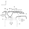
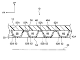
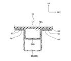
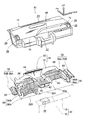
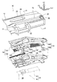
- FIG. 2 is a cross-sectional view of a principal part of the instrument panel shown in FIG. 1 cut along line 2-2. It is the principal part expansion perspective view which looked at the reinforcement part shown by FIG. 1 from the vehicle up-down direction lower side (back side). It is a principal part expanded sectional view of the instrument panel shown by FIG. FIG. 5 is an essential part enlarged cross-sectional view of the instrument panel shown in FIG. 1 cut along line 5-5. It is sectional drawing which shows the modification of the instrument panel which concerns on 1st embodiment of this invention. It is a disassembled perspective view which shows the modification of the instrument panel which concerns on 1st embodiment of this invention.
- FIG. 9 is an enlarged cross-sectional view of a main part of the instrument panel shown in FIG. 8 cut along line 9-9. It is the principal part expansion perspective view which looked at the reinforcement part shown by FIG. 8 from the vehicle up-down direction upper side (front side). It is a principal part expanded sectional view of the instrument panel shown by FIG. It is a disassembled perspective view of the instrument panel which concerns on 3rd embodiment of this invention.
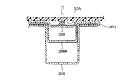
- FIG. 13 is an enlarged cross-sectional view of a main part of the instrument panel shown in FIG. 12 cut along line 13-13.
- an arrow UP, an arrow FR, and an arrow OUT indicate an upper side in the vehicle vertical direction, a front side in the vehicle front-rear direction, and an outer side (right side) in the vehicle width direction.
- the instrument panel 10 as the vehicle instrument panel according to the first embodiment of the present invention includes an instrument panel body 12 and a duct component member 14.
- the instrument panel body 12 is made of resin and is attached to an instrument panel reinforcement spanned between left and right front pillars (not shown).
- the instrument panel main body 12 is provided in the vehicle compartment and covers the vehicle structure 20 including the air conditioner 16 and the airbag device 18 provided in the vehicle from the upper side in the vehicle vertical direction.
- a center air conditioning outlet 22 as an air conditioning outlet and a center defroster outlet 24 as a defroster outlet are formed apart from each other in the vehicle longitudinal direction.
- a side air-conditioning outlet 26 and a side defroster outlet 28 are formed side by side in the vehicle vertical direction on both ends of the instrument panel 10 in the vehicle width direction.
- the instrument panel 10 is for left-hand drive vehicles. That is, in the instrument panel 10, the left side is the driver seat side, and the right side is the passenger seat side.
- the duct component 14 is made of resin, and is provided between the instrument panel body 12 and the vehicle structure 20.
- the duct constituent member 14 includes a first panel 30 and a second panel 32.
- the first panel 30 is configured to be smaller in the vehicle width direction than the second panel 32, and is provided on the vehicle vertical direction upper side with respect to the second panel 32 so as to face the vehicle width direction center portion 32 ⁇ / b> A of the second panel 32. ing.
- the first panel 30 and the second panel 32 are a center air-conditioning duct 42 as an air-conditioning duct that communicates the air outlet 34 of the air conditioner 16 and the center air-conditioning outlet 22, and the air outlet 34 and the center defroster of the air-conditioner 16.
- a center defroster duct 44 as a defroster duct that communicates with the air outlet 24 is configured.
- the first panel 30 includes an upper side wall portion 42 ⁇ / b> A that constitutes the upper side in the vehicle vertical direction of the center air-conditioning duct 42, and a part of the center defroster duct 44 on the rear side in the longitudinal direction of the vehicle.
- the first wall portion 44A is formed.
- the second panel 32 is formed with a lower wall portion 42B that forms the center air conditioning duct 42 with the upper wall portion 42A, and a second wall portion 44B that forms the center defroster duct 44 with the first wall portion 44A.
- the first wall portion 44A and the second wall portion 44B are formed with joint portions 46A and 46B, respectively.
- the joint portions 46A and 46B are connected to the center air conditioning outlet 22 and the center defroster blower in the instrument panel body 12. It is joined to the back surface 48 ⁇ / b> A of the central panel portion 48 formed between the outlet 24.
- a part of the upper side wall portion 42A is configured as a reinforcing portion 50. That is, as shown in FIG. 3, the reinforcing portion 50 is formed with a plurality of bead-like convex portions 52 that are convex upward in the vehicle vertical direction (on the instrument panel main body 12 side).
- Each of the plurality of convex portions 52 is formed in a regular hexagonal shape in plan view, and a connecting portion 53 that connects the base end sides (the vehicle vertical direction lower side) of the plurality of convex portions 52 is formed in a honeycomb shape as a whole. Is arranged to form.
- the plurality of convex portions 52 includes a first group of convex portions 52 (for example, a plurality of convex portions 52 arranged in the vertical direction surrounded by the square A) and a second group of convex portions 52. (For example, a plurality of convex portions 52 arranged in the vertical direction surrounded by a square B) are arranged so that no linear broken line exists.
- the first group of convex portions 52 and the second group of convex portions 52 that are parallel to each other are surrounded by a plurality of convex portions 52 and a square B that are arranged in the vertical direction surrounded by the square A described above.
- a plurality of convex portions 52 arranged in the vertical direction for example, a plurality of convex portions 52 arranged in an oblique direction surrounded by a square C and a plurality of convex portions 52 arranged in an oblique direction surrounded by a square D, and particularly illustrated
- a plurality of protrusions 52 arranged in an oblique direction different from the plurality of protrusions 52 arranged in the horizontal direction and the plurality of protrusions 52 arranged in the horizontal direction in parallel with the plurality of protrusions 52 surrounded by the squares C and D This also applies to the portion 52 and a plurality of convex portions 52 arranged in an oblique direction in parallel therewith.
- the front end surfaces of the plurality of convex portions 52 are load receiving surfaces 52A, and are formed in a flat shape. As shown in FIG. 4, each load receiving surface 52 ⁇ / b> A is joined to the back surface 48 ⁇ / b> A of the central panel portion 48 by, for example, welding.
- the general part in this reinforcement part 50 is made into the connection part 54 which comprises honeycomb form, and has connected the base end side (vehicle vertical direction lower side) of the some convex part 52.
- positioned between the instrument panel main body 12 and the connection part 54 plays a role of a reinforcement rib.
- the second panel 32 includes a side air conditioning duct 56 that communicates the air outlet 34 of the air conditioner 16 and the side air outlet 26, and the air outlet 34 and side defroster of the air conditioner 16.
- a side defroster duct upstream portion 58 ⁇ / b> A that forms the upstream side of the side defroster duct 58 that communicates with the air outlet 28 is formed.
- the side air-conditioning duct 56 and the side defroster duct upstream portion 58A are each formed in a cross-sectional hat shape opened to the instrument panel body 12 side.
- a side defroster duct downstream portion 58B is integrally formed via an integral hinge 60 on the vehicle width direction outer side of the downstream portion 56B of the side air conditioning duct 56.
- the side defroster duct downstream portion 58 ⁇ / b> B has a hat shape in cross section, and is folded back from the integral hinge 60 so as to overlap the downstream portion 56 ⁇ / b> B of the side air conditioning duct 56 in the vehicle vertical direction. Has been.
- joint portions 62 are formed on both sides of the side defroster duct downstream portion 58B.
- the joint 62 is overlapped with the joints 64 formed on both sides of the side air conditioning duct 56 in a state where the downstream side defroster duct 58B is folded as described above.
- the joint 64 is joined to the back surface 12A of the instrument panel main body 12 together with the joint 62 by, for example, welding in a state where the joint 64 is overlapped with the joint 62.
- the side defroster duct downstream portion 58B has a structure in which one end is opened and the other end is terminated, and as described above, the side defroster duct is overlapped with the side air conditioning duct 56 in the vehicle vertical direction.
- the downstream side of the side defroster duct 58 is configured to communicate with the side defroster duct upstream portion 58A.
- the closed cross section formed by the side defroster duct downstream portion 58B constitute a ventilation path that communicates the air blowing port 34 of the air conditioner 16 and the side air conditioning blower 26.
- a closed cross section constituted by the side defroster duct upstream portion 58A and the instrument panel main body 12, a side defroster duct downstream portion 58B, and the instrument panel constitutes an air passage that communicates the air outlet 34 of the air conditioner 16 and the side defroster outlet 28.
- the 1st panel 30 and the 2nd panel 32 which comprise this duct structural member 14 are integrally formed by the predetermined molding machine. That is, in this molding machine, the first panel 30 and the vehicle width direction center portion 32A of the second panel 32 facing the first panel 30 are formed by, for example, blow molding, and the vehicle width of the second panel 32 is determined. The direction both ends 32B are formed by, for example, vacuum forming.
- the second panel 32 is formed with a plurality of joint portions other than the joint portion 46B and the joint portions 62 and 64 described above. It is joined to the back surface of the ment panel body 12.
- the upper side of the center air conditioning duct 42 in the vertical direction of the vehicle is constituted by the upper side wall portion 42A of the first panel 30. Therefore, even if the above-described conditioned air is cold air, the cold air does not directly contact the back surface of the instrument panel main body 12, so that dew condensation occurs on the surface of the instrument panel main body 12 corresponding to the center air conditioning duct 42. This can be suppressed.
- the upper side wall portion 42A is formed integrally with the first panel 30, in order to suppress the occurrence of condensation on the surface of the instrument panel body 12, a heat insulating material or the like is provided separately from the first panel 30. It is possible to eliminate the necessity of providing another member.
- the reinforcement part 50 is formed in 42 A of upper side wall parts, and this reinforcement part 50 is each in the instrument panel main body 12 side, as FIG. 4 shows.
- a plurality of convex portions 52 that are convex and have a load receiving surface 52A at the tip thereof, and a connecting portion 54 that connects the base end sides of the plurality of convex portions 52 are formed. Further, the load receiving surfaces 52A of the plurality of convex portions 52 are all joined to the back surface 48A (surface on the vehicle structure 20 side) of the central panel portion 48.
- the central panel portion 48 is necessary even when a load or an impact is applied to the central panel portion 48. It can suppress that it deform
- the load or the impact is received at the load receiving surface 52A of each convex portion 52. Concentration of stress on this part is also suppressed. Thereby, even when a load or an impact is applied to the central panel part 48, the crack of the central panel part 48 can be suppressed.
- the instrument panel main body 12 can be thinned, and the weight and cost can be reduced.
- the reinforcing portion 50 since a part of the first panel 30 is used as the reinforcing portion 50, an increase in the number of parts can be avoided, and further weight reduction and cost reduction can be achieved.
- the plurality of convex portions 52 has no linear broken line between the first group of convex portions 52 and the second group of convex portions 52 that are parallel to each other.
- the rigidity of the reinforcement part 50 can be ensured by suppressing the 50 folding.
- the space between the plurality of convex portions 52 serves as a resonance cell, a sound absorption effect due to the sound resonance effect can also be exhibited.
- the sound-absorbing material arranged on the back side of the instrument panel main body 12 can be reduced in size or eliminated.
- both end portions 32B in the vehicle width direction of the second panel 32 shown in FIG. 1 are formed by vacuum forming, it is possible to reduce the thickness of this portion, and it is possible to further reduce the weight and cost.
- side defroster duct downstream portion 58B is folded back from the integral hinge 60 to cross the downstream portion 56B of the side air conditioning duct 56 and the side defroster duct downstream portion 58B.
- An integrated structure of the side air conditioning duct 56 and the side defroster duct 58 can be established with a simple configuration without restricting the arrangement with the outlet 28.
- the reinforcing portion 50 is formed on the upper side wall portion 42A constituting the center air conditioning duct 42.
- the reinforcing portion 50 may be configured as follows.
- a reinforcing part 70 is formed on the first panel 30 in addition to the reinforcing part 50.
- the reinforcing portion 70 is formed continuously with the first wall portion 44A and is disposed between the first wall portion 44A and the upper side wall portion 42A (that is, the center air conditioning duct 42 and the center defroster duct). 44).
- the reinforcing portion 70 has the same configuration as the above-described reinforcing portion 50 (see FIGS. 3 and 4).
- the reinforcing portion 70 is arranged side by side so as to be continuous with the reinforcing portion 70 in the vehicle front-rear direction. 50 and the instrument panel body 12 are reinforced.
- the reinforcing part 50 may not be formed on the upper side wall part 42A.
- both ends 32B of the 2nd panel 32 were each formed by vacuum forming, the whole of the 1st panel 30 and the 2nd panel 32 was each formed by vacuum forming, respectively. May be. Further, other portions of the first panel 30 and the second panel 32 may be formed by vacuum forming.
- the reinforcement part 50 was formed in the 1st panel 30, as FIG. 7 shows, the right side panel part 72 and the left side panel part 74 of the instrument panel main body 12 in the 2nd panel 32 are shown. Reinforcing portions 80 and 82 similar to the reinforcing portion 50 may be formed at the joint portion. Note that only one of the reinforcing portions 80 and 82 may be formed.
- the plurality of convex portions 52 are each formed in a hexagonal shape in plan view, but may be formed in a circular shape in plan view.
- the load receiving surfaces 52A of the plurality of convex portions 52 are all joined to the back surface 48A of the central panel portion 48, but any one of the plurality of convex portions 52 (for example, six pieces)
- the load receiving surface 52A of the central convex portion 52) surrounded by the convex portion 52 may not be joined to the back surface 48A of the central panel portion 48. That is, it is only necessary that the load receiving surface 52 ⁇ / b> A of at least one of the plurality of convex portions 52 is bonded to the back surface 48 ⁇ / b> A of the central panel portion 48.
- the several convex part 52 was formed along with the two directions which mutually cross
- the 1st panel 30 and the 2nd panel 32 and the separate sheet material 68 are provided, and this sheet material 68 is the side air-conditioning duct 56.
- the upstream portion 56A and the side defroster duct upstream portion 58A may be joined in a state of being overlapped with the second panel 32 so as to close the opening on the instrument panel main body 12 side. That is, the upper side in the vehicle vertical direction of the upstream portion 56A of the side air conditioning duct 56 and the upstream side portion 58A of the side defroster duct may be configured by the seat material 68.
- an instrument panel 90 as a vehicle instrument panel according to the second embodiment of the present invention includes an instrument panel body 12 and a duct component member 94.
- the instrument panel body 12 has the same configuration as that of the first embodiment of the present invention.
- the right panel portion 72 and the left panel portion 74 of the instrument panel body 12 are reinforced by reinforcing portions 120 and 122, which will be described later.
- the duct constituent member 94 is made of resin and is provided between the instrument panel body 12 and the vehicle structure 20.
- the duct constituting member 94 includes a first panel 100 and a second panel 102 disposed on the vehicle vertical direction lower side.
- the first panel 100 and the second panel 102 include a center air conditioning duct 112 as an air conditioning duct that communicates the air outlet 34 of the air conditioner 16 and the center air outlet 22, and the air outlet 34 and the center defroster of the air conditioner 16.
- a center defroster duct 114 as a defroster duct that communicates with the air outlet 24, a side air conditioning duct 116 as an air conditioning duct that communicates the air outlet 34 of the air conditioner 16 and the side air outlet 26, and an air outlet of the air conditioner 16
- a side defroster duct 118 serving as a defroster duct that communicates between the side defroster air outlet 34 and the side defroster outlet 28 is configured.
- the first panel 100 includes an upper wall portion 112A that constitutes the vehicle vertical direction upper side of the center air-conditioning duct 112, a first wall portion 114A that constitutes a part of the center defroster duct 114 on the rear side in the vehicle longitudinal direction, 116 A of upper side walls which comprise the vehicle up-down direction upper side of the side air conditioning duct 116, and 118 A of upper side walls which comprise the vehicle up-down direction upper side of the side defroster duct 118 are formed.
- the second panel 102 includes a lower wall portion 112B that forms the center air conditioning duct 112 with the upper wall portion 112A, a second wall portion 114B that forms the center defroster duct 114 with the first wall portion 114A, A lower side wall part 116B constituting the side air conditioning duct 116 with the side wall part 116A and a lower side wall part 118B constituting the side defroster duct 118 with the upper side wall part 118A are formed.
- the first panel 100 and the second panel 102 are individually formed by, for example, vacuum molding, injection molding, or the like.
- the junction part 162 with the instrument panel main body 12 in the 2nd panel 102 is the state overlapped with the junction part 164 with the instrument panel main body 12 in the 1st panel 100, and this. Together with the joint portion 164 (at the same time as the joint portion), it is joined to the back surface 12A of the instrument panel body 12 by welding or the like, for example.
- the other joint portion of the second panel 102 is also overlapped with the other joint portion of the first panel 100, and together with this joint portion (at the same time as this joint portion), the instrument panel main body For example, it is joined to the back surface 12A of 12 by welding or the like.
- the duct component 94 includes portions other than the center air conditioning duct 112, the center defroster duct 114, the side air conditioning duct 116, and the side defroster duct 118, and the right panel portion 72 and the left side. Reinforcing portions 120 and 122 are respectively formed at portions facing the panel portion 74 in the vehicle vertical direction.
- the pair of reinforcing portions 120 and 122 have substantially the same configuration. Therefore, here, the right side (passenger seat side) reinforcing portion 120 will be described, and the left side (driver's seat side) reinforcing portion 122 will not be described.
- the reinforcing part 120 includes a first reinforcing panel part 124 formed on the first panel 100 and a second reinforcing panel part 126 as a connecting part formed on the second panel 102.
- a plurality of beads 130 are formed on the first reinforcing panel portion 124 so as to protrude downward in the vehicle vertical direction.
- the plurality of beads 130 are formed side by side in two directions (X direction and Y direction) intersecting each other along the right panel portion 72 (see FIG. 8) formed in the instrument panel body 12 described above.
- the first reinforcing panel portion 124 includes an upper side in the vehicle vertical direction (instrument panel) between the bottom surfaces 130 ⁇ / b> A adjacent to the plurality of beads 130. It can be said that convex portions 132 are formed on the main body 12 side). The plurality of convex portions 132 are continuously formed so as to form a honeycomb shape as a whole.
- the tip surfaces of the plurality of convex portions 132 are load receiving surfaces 132A, and are formed in a flat shape. As shown in FIG. 11, each load receiving surface 132 ⁇ / b> A is joined to the back surface 72 ⁇ / b> A (surface on the vehicle structure 20 side) of the right panel portion 72 by welding or the like, for example.
- the bottom surface 130 ⁇ / b> A of each of the beads 130 described above is joined to the second reinforcing panel portion 126, whereby the base end sides of the plurality of convex portions 132 are connected by the second reinforcing panel portion 126.
- positioned between the instrument panel main body 12 and the 2nd reinforcement panel part 126 plays a role of a reinforcement rib.
- the reinforcing portion 120 is disposed away from the vehicle structure 20 covered by the instrument panel body 12 in the vehicle vertical direction.
- the instrument panel 90 when conditioned air is sent from the air blowing port 34 of the air conditioner 16 shown in FIG. 8 to the center air conditioning duct 112, the conditioned air is guided to the center air conditioning outlet 22 through the center air conditioning duct 112. The air is blown out from the center air-conditioning outlet 22 into the passenger compartment.
- the upper side of the center air conditioning duct 112 in the vertical direction of the vehicle is constituted by the upper wall portion 112A of the first panel 100. Therefore, even if the above-described conditioned air is cold air, the cold air does not directly contact the back surface of the instrument panel main body 12, so that it is possible to suppress the occurrence of condensation on the surface of the instrument panel main body 12. .
- the upper side of the side air conditioning duct 116 in the vertical direction of the vehicle is constituted by the upper wall portion 116A of the first panel 100. Therefore, even when cold air is sent from the air blowing port 34 of the air conditioner 16 to the side air conditioning duct 116, the cold air does not directly contact the back surface of the instrument panel main body 12, so condensation is formed on the surface of the instrument panel main body 12. Can be prevented from occurring.
- these upper side wall portions 112A and 116A are formed integrally with the first panel 100, in order to suppress the occurrence of condensation on the surface of the instrument panel main body 12, separately from the first panel 100.
- the need to provide a separate member such as a heat insulating material can also be eliminated.
- the duct component member 94 is formed with a reinforcing portion 120.
- each of the reinforcing portions 120 has a projection on the instrument panel main body 12 side and a load receiving portion at the tip thereof.
- a plurality of convex portions 132 having a surface 132A and a second reinforcing panel portion 126 that connects the base end sides of the plurality of convex portions 132 are formed.
- the load receiving surfaces 132 ⁇ / b> A of the plurality of convex portions 132 are all joined to the back surface 72 ⁇ / b> A of the right panel portion 72.
- the right panel portion 72 is more than necessary. Deformation can be suppressed. Moreover, when a load or impact is applied to the right panel portion 72, the load receiving surface 132A of each convex portion 132 receives the load or impact, so that the stress is dispersed at each load receiving surface 132A, and the right panel portion 72 is identified. Concentration of stress on this part is also suppressed. Thereby, even when a load or an impact is applied to the right panel portion 72, the right panel portion 72 can be prevented from cracking.
- the instrument panel main body 12 can be thinned, and the weight and cost can be reduced.
- the reinforcing portions 120 and 122 are formed in portions other than the center air conditioning duct 112, the center defroster duct 114, the side air conditioning duct 116, and the side defroster duct 118. Therefore, for example, it is possible to avoid restricting the arrangement and shape of these ducts or affecting the air flow in these ducts.
- the plurality of convex portions 132 are formed continuously so as to form a honeycomb shape as a whole, so that the reinforcing portion 120 is not bent. It can suppress and can secure the rigidity of reinforcement part 120.
- the space between the plurality of convex portions 132 serves as a resonance cell, a sound absorption effect due to the sound resonance effect can also be exhibited.
- the sound-absorbing material arranged on the back side of the instrument panel main body 12 can be reduced in size or eliminated.
- the joint part (joint part 162 or other joint part) with the instrument panel body 12 in the second panel 102 is a joint part with the instrument panel body 12 in the first panel 100.
- the joint portion of the second panel 102 can be joined to the back surface 12A of the instrument panel body 12 together with the joint portion of the first panel 100 in one process, the assembly process can be shortened.
- the plurality of beads 130 are each formed in a hexagonal shape in plan view, but may be formed in a circular shape in plan view.
- the load receiving surfaces 132A of the plurality of convex portions 132 are all joined to the back surface 72A of the right panel portion 72.
- the surface 132A may not be joined to the back surface 72A of the right panel portion 72. That is, it is only necessary that the load receiving surface 132 ⁇ / b> A of at least one of the plurality of protrusions 132 is bonded to the back surface 72 ⁇ / b> A of the right panel portion 72.
- the plurality of protrusions 132 are formed so as to form a honeycomb as a whole, but may extend in a specific direction and be formed in parallel to each other.
- a reinforcing portion similar to the reinforcing portion 50 (see FIGS. 1 to 4) in the first embodiment may be formed on the upper side wall portion 112A.
- a reinforcing portion similar to the reinforcing portion 70 (see FIG. 6) in the embodiment is formed continuously with the first wall portion 114A, and is disposed between the first wall portion 114A and the upper side wall portion 112A. good.
- the reinforcement parts 120 and 122 were formed in the junction part with the right side panel part 72 and the left side panel part 74 of the instrument panel main body 12 in the duct structural member 94, respectively, Only one of them may be formed.
- an instrument panel 190 as a vehicle instrument panel according to the third embodiment of the present invention includes an instrument panel main body 12 and a duct constituent member 194.
- the instrument panel body 12 has the same configuration as that of the first and second embodiments of the present invention.
- the duct component 194 is configured by a first panel 200 disposed on the upper side in the vehicle vertical direction and a second panel 202 disposed on the lower side in the vehicle vertical direction.
- the outer shape of the first panel 200 is smaller than the outer shape of the second panel 202.
- the first panel 200 and the second panel 202 constitute a center air conditioning duct 212, a center defroster duct 214, a side air conditioning duct 216, and a side defroster duct 218 as in the second embodiment.
- the lower second panel 202 includes a lower side wall portion 212 ⁇ / b> B having a hat-shaped cross section that forms the center air-conditioning duct 212 and a part of the front side in the vehicle front-rear direction of the center defroster duct 214.
- the second wall portion 214 ⁇ / b> B to be configured, the side air-conditioning duct 216 having a cross-sectional hat shape whose upper side (instrument panel body 12 side) is open, and the upstream side of the side defroster duct 218 which is formed in a cross-sectional hat shape whose upper side is open.
- the side defroster duct upstream part 218A which comprises is formed.
- a center defroster duct 214 is formed by an upper side wall portion 212A having a hat-shaped cross section with a lower wall portion 212B and the lower wall portion 212B open at the lower side, and a second wall portion 214B.
- a first wall portion 214A constituting a part of the rear side in the vehicle front-rear direction and a seat portion 268 that closes an opening on the instrument panel body 12 side in the side air conditioning duct 216 and the side defroster duct upstream portion 218A are formed. Yes. It is preferable that a heat-insulating space is formed between the seat portion 268 and the back surface of the instrument panel body 12 by forming a concave portion having a shallow depth that protrudes downward.
- the first panel 200 and the second panel 202 are joined to the back surface of the instrument panel body 12 by welding, for example, in a state where they are overlapped with each other. However, in the region where the outer shape of the first panel 200 is small, the second panel 202 is joined to the back surface of the instrument panel body 12 at the peripheral edge.
- the downstream side portion 218 ⁇ / b> B of the side defroster duct having a hat-shaped cross section in which the peripheral portion of the first panel 200 on both sides in the vehicle width direction is extended and the upper side that protrudes toward the side air conditioning duct 216 is opened. Is formed.
- an upper side wall portion 258 of a side defroster duct is integrally formed via an integral hinge 260 on the vehicle width direction outer side of the side air conditioning duct 216 in the second panel 202 corresponding thereto.
- This side defroster duct upper side wall portion 258 is formed in a hat shape having a shallower depth than the side defroster duct downstream portion 218B.
- the side defroster duct upper side wall portion 258 forms a heat insulating space 266 with the rear surface 12A of the instrument panel main body 12 in the assembled state to the vehicle. Yes.
- the side defroster duct downstream part 218B is piled up in the up-down direction in the side air-conditioning duct 216 of the 2nd panel 202.
- the side defroster duct upper side wall portion 258 is folded back with the integral hinge 260 as a starting point, and the side defroster duct downstream portion 218B is sandwiched between the side air conditioning duct 216 and the side defroster duct upper side wall portion 258.
- the side air-conditioning duct 216, the side defroster duct downstream portion 218B, and the side defroster duct upper side wall portion 258 that are superposed in the vertical direction are joined to the back surface 12A of the instrument panel main body 12 at the joint surfaces that are superposed on each other.
- the first panel 200 is overlapped with the first panel 30 of the above-described first embodiment so that the peripheral edge thereof is extended to cover the side air conditioning duct 216 and the side defroster duct upstream part 218A from above.
- This can be regarded as a structure joined to the two panel 202.
- the side air conditioning duct 216 and the side defroster duct downstream portion 218 ⁇ / b> B are formed side by side in the vehicle vertical direction by the peripheral edge extended from the first panel 200.
- the side air-conditioning duct 216 and the side defroster duct 218 can be integrated with a simple configuration without restricting the arrangement of the air outlet and the side defroster outlet 28.
- the opening on the instrument panel main body 12 side in the side air conditioning duct 216 and the side defroster duct upstream portion 218A is closed by the seat portion 268. Therefore, even when cold air is circulated in the side air conditioning duct 216 and the side defroster duct 218, the cold air does not directly contact the back surface of the instrument panel body 12, and therefore the upstream side of the side air conditioning duct 216 and the side defroster duct. It is possible to suppress the occurrence of condensation on the surface of the instrument panel body 12 corresponding to 218A.
- the opening on the instrument panel body 12 side in the side defroster duct downstream portion 218B is closed by the side defroster duct upper side wall portion 258. Therefore, even when cold air is circulated in the side defroster duct 218, the cold air does not directly contact the back surface of the instrument panel main body 12, so that the instrument panel main body 12 corresponding to the side defroster duct downstream portion 218B It is possible to suppress the occurrence of condensation on the surface.
- the first panel 200 and the second panel 202 may be formed with reinforcing portions having a plurality of convex portions similar to those in the first and second embodiments described above. (See FIGS. 1, 7, and 8).
Landscapes
- Physics & Mathematics (AREA)
- Thermal Sciences (AREA)
- Engineering & Computer Science (AREA)
- Mechanical Engineering (AREA)
- Instrument Panels (AREA)
- Air-Conditioning For Vehicles (AREA)
Abstract
Description
はじめに、本発明の第一実施形態について説明する。
次に、本発明の第二実施形態について説明する。
次に、本発明の第三実施形態について説明する。
Claims (16)
- 空調装置を有する車両構造体を車両上下方向上側から覆うと共に、空調吹出口とデフロスタ吹出口とが形成されたインストルメントパネル本体と、
前記インストルメントパネル本体に対する車両上下方向下側に配置されて前記インストルメントパネル本体に接合されると共に、前記空調装置の送風口と前記空調吹出口とを連通する空調ダクトの車両上下方向上側を構成する上側壁部と、前記空調装置の送風口と前記デフロスタ吹出口とを連通するデフロスタダクトの一部を構成する第一壁部とが形成された第一パネルと、
前記第一パネルに対する車両上下方向下側に配置されて前記インストルメントパネル本体に接合されると共に、前記上側壁部とで前記空調ダクトを構成する下側壁部と、前記第一壁部とで前記デフロスタダクトを構成する第二壁部とが形成された第二パネルと、
を備えた車両用インストルメントパネル。 - 前記第一パネル及び第二パネルの少なくとも一方には、それぞれ前記インストルメントパネル本体側に凸を成しその先端に荷重受け面を有する複数の凸部と、前記複数の凸部の基端側を連結する連結部とを有する補強部が形成され、
前記複数の凸部のうち少なくともいずれか複数の凸部の荷重受け面は、前記インストルメントパネル本体の裏面に接合されている、
請求項1に記載の車両用インストルメントパネル。 - 前記複数の凸部は、互いに並列する第一群の凸部と第二群の凸部との間に直線状の折れ線が存在しないように配列されている、
請求項2に記載の車両用内装パネル。 - 前記複数の凸部は、全体としてハニカム状を成すように互いに連続して形成されている、
請求項2に記載の車両用内装パネル。 - 前記補強部は、前記上側壁部に形成されている、
請求項2~請求項4のいずれか一項に記載の車両用インストルメントパネル。 - 前記補強部は、前記空調ダクト及び前記デフロスタダクト以外の部分に形成されている、
請求項2~請求項4のいずれか一項に記載の車両用インストルメントパネル。 - 前記補強部は、前記第一壁部と連続して形成されると共に、前記第一壁部と前記上側壁部との間に配置されている、
請求項6に記載の車両用インストルメントパネル。 - 前記補強部は、前記インストルメントパネル本体の右側パネル部及び左側パネル部の少なくとも一方との接合部に形成されている、
請求項6に記載の車両用インストルメントパネル。 - 前記補強部は、
前記第一パネルに形成され、前記複数の凸部が形成された第一補強パネル部と、
前記第二パネルに形成された前記連結部としての第二補強パネル部と、
を有する、
請求項2~請求項4のいずれか一項に記載の車両用インストルメントパネル。 - 前記第二パネルにおける前記インストルメントパネル本体との接合部は、前記第一パネルにおける前記インストルメントパネル本体との接合部と重ね合わされた状態で該接合部と共に前記インストルメントパネル本体の裏面に接合されている、
請求項1~請求項9のいずれか一項に記載の車両用インストルメントパネル。 - 前記インストルメントパネル本体の車両幅方向両端側には、サイド空調吹出口とサイドデフロスタ吹出口とが車両上下方向に並んで形成され、
前記第二パネルには、
前記空調装置の送風口と前記サイド空調吹出口とを連通するサイド空調ダクトと、
前記空調装置の送風口と前記サイドデフロスタ吹出口とを連通するサイドデフロスタダクトの上流側を構成するサイドデフロスタダクト上流部と、
前記サイド空調ダクトの車両幅方向外側にインテグラルヒンジを介して一体に形成されると共に、前記インテグラルヒンジを起点に折り返されて前記サイド空調ダクトと車両上下方向に重ね合わされた状態で前記サイド空調ダクトと共に前記インストルメントパネル本体の裏面に接合され、且つ、前記サイドデフロスタダクト上流部と連通されて前記サイドデフロスタダクトの下流側を構成するサイドデフロスタダクト下流部とが形成されている、
請求項1~請求項8のいずれか一項に記載の車両用インストルメントパネル。 - 前記インストルメントパネル本体の車両幅方向両端側には、サイド空調吹出口とサイドデフロスタ吹出口とが形成され、
前記第二パネルには、前記空調装置の送風口と前記サイド空調吹出口とを連通するサイド空調ダクトと、前記空調装置の送風口と前記サイドデフロスタ吹出口とを連通するサイドデフロスタダクトとがそれぞれ前記インストルメントパネル本体側に開放された断面ハット状に形成され、
前記サイド空調ダクト及び前記サイドデフロスタダクトにおける前記インストルメントパネル本体側の開放口を塞ぐシート材を備えた、
請求項1~請求項8のいずれか一項に記載の車両用インストルメントパネル。 - 前記第一パネル及び前記第二パネルの少なくとも一部は、真空成形によって形成されている、
請求項1~請求項12のいずれか一項に記載の車両用インストルメントパネル。 - 前記インストルメントパネル本体の車両幅方向両端側には、サイド空調吹出口とサイドデフロスタ吹出口とが車両上下方向に並んで形成され、
前記第二パネルには、
前記空調装置の送風口と前記サイド空調吹出口とを連通するサイド空調ダクトと、前記空調装置の送風口と前記サイドデフロスタ吹出口とを連通するサイドデフロスタダクトの上流側を構成するサイドデフロスタダクト上流部とがそれぞれ前記インストルメントパネル本体側に開放された断面ハット状に形成され、
前記第一パネルには、その周縁部が延長されて前記サイド空調ダクトと車両上下方向に重ね合わされた状態で前記サイド空調ダクトと共に前記インストルメントパネル本体の裏面に接合され、且つ、前記サイドデフロスタダクトの下流側を構成するサイドデフロスタダクト下流部が形成されている、
請求項1に記載の車両用インストルメントパネル。 - 前記第一パネルには、前記サイド空調ダクト及び前記サイドデフロスタダクト上流部における前記インストルメントパネル本体側の開放口を塞ぐシート部が形成されている、
請求項14に記載の車両用インストルメントパネル。 - 前記サイドデフロスタダクト下流部は、インストルメントパネル本体側に開放された断面ハット状に形成され、
前記第二パネルには、前記サイド空調ダクトの車両幅方向外側にインテグラルヒンジを介して一体に形成されると共に、前記インテグラルヒンジを起点に折り返されて前記第一パネルのサイドデフロスタダクト下流部と車両上下方向に重ね合わされた状態で前記サイド空調ダクト及び前記サイドデフロスタダクト下流部と共に前記インストルメントパネル本体の裏面に接合され、且つ、前記サイドデフロスタダクト下流部における前記インストルメントパネル本体側の開放口を塞ぐサイドデフロスタダクト上側壁部が形成されている、
請求項14又は請求項15に記載の車両用インストルメントパネル。
Priority Applications (6)
| Application Number | Priority Date | Filing Date | Title |
|---|---|---|---|
| PCT/JP2010/054856 WO2011114521A1 (ja) | 2010-03-19 | 2010-03-19 | 車両用インストルメントパネル |
| EP14193156.8A EP2860056B1 (en) | 2010-03-19 | 2010-03-19 | Vehicle instrument panel |
| JP2012505418A JP5293881B2 (ja) | 2010-03-19 | 2010-03-19 | 車両用インストルメントパネル |
| US13/635,767 US8821225B2 (en) | 2010-03-19 | 2010-03-19 | Vehicle instrument panel |
| EP10847932.0A EP2548756B1 (en) | 2010-03-19 | 2010-03-19 | Vehicle instrument panel |
| CN201080065598.2A CN102811880B (zh) | 2010-03-19 | 2010-03-19 | 车辆用仪表板 |
Applications Claiming Priority (1)
| Application Number | Priority Date | Filing Date | Title |
|---|---|---|---|
| PCT/JP2010/054856 WO2011114521A1 (ja) | 2010-03-19 | 2010-03-19 | 車両用インストルメントパネル |
Publications (1)
| Publication Number | Publication Date |
|---|---|
| WO2011114521A1 true WO2011114521A1 (ja) | 2011-09-22 |
Family
ID=44648647
Family Applications (1)
| Application Number | Title | Priority Date | Filing Date |
|---|---|---|---|
| PCT/JP2010/054856 Ceased WO2011114521A1 (ja) | 2010-03-19 | 2010-03-19 | 車両用インストルメントパネル |
Country Status (5)
| Country | Link |
|---|---|
| US (1) | US8821225B2 (ja) |
| EP (2) | EP2860056B1 (ja) |
| JP (1) | JP5293881B2 (ja) |
| CN (1) | CN102811880B (ja) |
| WO (1) | WO2011114521A1 (ja) |
Cited By (3)
| Publication number | Priority date | Publication date | Assignee | Title |
|---|---|---|---|---|
| CN103158559A (zh) * | 2011-12-14 | 2013-06-19 | 苏州万隆汽车零部件股份有限公司 | 一种重卡用集成式仪表板 |
| DE102014209323A1 (de) * | 2014-05-16 | 2015-11-19 | Mahle International Gmbh | Kunststoffbauteil |
| KR101763773B1 (ko) | 2011-10-24 | 2017-08-02 | 현대모비스 주식회사 | 차량용 인스트루먼트 패널 |
Families Citing this family (12)
| Publication number | Priority date | Publication date | Assignee | Title |
|---|---|---|---|---|
| JP6295653B2 (ja) * | 2013-12-26 | 2018-03-20 | 三菱自動車工業株式会社 | 車両用空調装置のダクト |
| CN105575951B (zh) * | 2015-12-25 | 2017-10-27 | 厦门市三安光电科技有限公司 | 高压发光二极管及其制作方法 |
| US20170313281A1 (en) * | 2016-04-28 | 2017-11-02 | GM Global Technology Operations LLC | Defrost duct with acoustic material inserts |
| JP6429403B2 (ja) * | 2016-09-26 | 2018-11-28 | 株式会社Subaru | 内装材 |
| USD837118S1 (en) * | 2016-11-14 | 2019-01-01 | Honda Motor Co., Ltd. | Instrument panel |
| CN107021139B (zh) * | 2017-03-28 | 2019-06-04 | 北京新能源汽车股份有限公司 | 仪表板组件和具有它的车辆 |
| DE102017220264A1 (de) | 2017-11-14 | 2019-05-16 | Bayerische Motoren Werke Aktiengesellschaft | Einstellbare lenkradbelüftung |
| JP7031367B2 (ja) * | 2018-02-28 | 2022-03-08 | トヨタ自動車株式会社 | インストルメントパネル上面部連結構造 |
| JP7020188B2 (ja) * | 2018-03-02 | 2022-02-16 | トヨタ自動車株式会社 | インストルメントパネル構造 |
| JP7143746B2 (ja) * | 2018-12-04 | 2022-09-29 | トヨタ自動車株式会社 | インストルメントパネル構造 |
| CN111497616A (zh) * | 2019-01-30 | 2020-08-07 | 长城汽车股份有限公司 | 仪表板总成和具有其的车辆 |
| JP7240644B2 (ja) * | 2021-03-19 | 2023-03-16 | いすゞ自動車株式会社 | 車両のダッシュパネル及び車両のダッシュパネル取付構造 |
Citations (14)
| Publication number | Priority date | Publication date | Assignee | Title |
|---|---|---|---|---|
| JPH0752683A (ja) | 1993-05-14 | 1995-02-28 | Kansei Corp | 車両用インストルメントパネル部構造 |
| JPH0880762A (ja) | 1994-09-09 | 1996-03-26 | Toyota Auto Body Co Ltd | インストルメントパネル |
| JPH08268041A (ja) | 1995-03-30 | 1996-10-15 | Nishikawa Kasei Co Ltd | 樹脂製部品の接合構造、該樹脂製部品の接合部の弾性シール材及び該樹脂製部品の接合方法 |
| JPH10250414A (ja) | 1997-03-18 | 1998-09-22 | Mitsubishi Motors Corp | インストルメントパネルの構造及び組立方法 |
| JPH10309926A (ja) * | 1997-05-08 | 1998-11-24 | Nissan Shatai Co Ltd | 車両用空調装置のダクト構造 |
| JP2001294034A (ja) * | 2000-04-11 | 2001-10-23 | Inoac Corp | 空気案内ダクトの空気整流構造 |
| JP2001301490A (ja) * | 2000-04-25 | 2001-10-31 | Nissan Shatai Co Ltd | インストルメントパネル構造およびインストルメントパネルの製造方法 |
| JP2002087045A (ja) * | 2000-09-19 | 2002-03-26 | Toyoda Gosei Co Ltd | 空調用ダクト |
| JP2002087114A (ja) | 2000-09-18 | 2002-03-26 | Mitsuboshi Belting Ltd | 空調ダクト一体インストルメントパネル構造及びその製造方法 |
| JP2002144847A (ja) * | 2000-11-10 | 2002-05-22 | Honda Motor Co Ltd | 車両用インストルメントパネル−空調用ダクト集合体 |
| JP2002178794A (ja) * | 2000-12-11 | 2002-06-26 | Zexel Valeo Climate Control Corp | インストルメントパネル構造 |
| JP2003136942A (ja) * | 2001-08-20 | 2003-05-14 | Denso Corp | 空調装置の車両搭載構造および車両搭載方法 |
| JP2004299480A (ja) | 2003-03-31 | 2004-10-28 | Mitsuboshi Belting Ltd | ダクト一体型インストルメントパネル |
| JP2005335628A (ja) * | 2004-05-28 | 2005-12-08 | Toyoda Gosei Co Ltd | 車両用空調ダクト及びその取付方法 |
Family Cites Families (10)
| Publication number | Priority date | Publication date | Assignee | Title |
|---|---|---|---|---|
| JPS5516747Y2 (ja) * | 1977-04-01 | 1980-04-18 | ||
| KR900000518B1 (ko) * | 1986-01-17 | 1990-01-31 | 마쯔다 가부시기가이샤 | 방풍유리 서리제거장치의 구조 |
| US5762395A (en) * | 1996-06-25 | 1998-06-09 | General Motors Corporation | Molded cross car support structure |
| JPH11165524A (ja) * | 1997-12-01 | 1999-06-22 | Moriroku Company Ltd | 自動車の空調用ダクト装置 |
| JPH11165563A (ja) * | 1997-12-01 | 1999-06-22 | Moriroku Company Ltd | 自動車の前部内装部品組立体 |
| JP2001213139A (ja) | 1999-11-26 | 2001-08-07 | Inoac Corp | 車両用空気案内ダクト |
| DE10215347A1 (de) * | 2001-04-10 | 2002-12-12 | Denso Corp | Fahrzeugklimatisierungs-Kanalstruktur, Verfahren zu deren Herstellung und Elektroverkabelungs-Struktur |
| FR2876958A1 (fr) * | 2004-10-21 | 2006-04-28 | Renault Sas | Dispositif de climatisation d'un vehicule comportant un reseau de canalisation de degivrage |
| JP2010006357A (ja) * | 2008-05-30 | 2010-01-14 | Aisin Seiki Co Ltd | 車両用パネル |
| EP2497673B1 (en) * | 2009-11-04 | 2016-01-06 | Toyota Jidosha Kabushiki Kaisha | Vehicle interior part, method of manufacturing thereof and mold thereof |
-
2010
- 2010-03-19 WO PCT/JP2010/054856 patent/WO2011114521A1/ja not_active Ceased
- 2010-03-19 JP JP2012505418A patent/JP5293881B2/ja not_active Expired - Fee Related
- 2010-03-19 CN CN201080065598.2A patent/CN102811880B/zh not_active Expired - Fee Related
- 2010-03-19 US US13/635,767 patent/US8821225B2/en not_active Expired - Fee Related
- 2010-03-19 EP EP14193156.8A patent/EP2860056B1/en not_active Not-in-force
- 2010-03-19 EP EP10847932.0A patent/EP2548756B1/en not_active Not-in-force
Patent Citations (14)
| Publication number | Priority date | Publication date | Assignee | Title |
|---|---|---|---|---|
| JPH0752683A (ja) | 1993-05-14 | 1995-02-28 | Kansei Corp | 車両用インストルメントパネル部構造 |
| JPH0880762A (ja) | 1994-09-09 | 1996-03-26 | Toyota Auto Body Co Ltd | インストルメントパネル |
| JPH08268041A (ja) | 1995-03-30 | 1996-10-15 | Nishikawa Kasei Co Ltd | 樹脂製部品の接合構造、該樹脂製部品の接合部の弾性シール材及び該樹脂製部品の接合方法 |
| JPH10250414A (ja) | 1997-03-18 | 1998-09-22 | Mitsubishi Motors Corp | インストルメントパネルの構造及び組立方法 |
| JPH10309926A (ja) * | 1997-05-08 | 1998-11-24 | Nissan Shatai Co Ltd | 車両用空調装置のダクト構造 |
| JP2001294034A (ja) * | 2000-04-11 | 2001-10-23 | Inoac Corp | 空気案内ダクトの空気整流構造 |
| JP2001301490A (ja) * | 2000-04-25 | 2001-10-31 | Nissan Shatai Co Ltd | インストルメントパネル構造およびインストルメントパネルの製造方法 |
| JP2002087114A (ja) | 2000-09-18 | 2002-03-26 | Mitsuboshi Belting Ltd | 空調ダクト一体インストルメントパネル構造及びその製造方法 |
| JP2002087045A (ja) * | 2000-09-19 | 2002-03-26 | Toyoda Gosei Co Ltd | 空調用ダクト |
| JP2002144847A (ja) * | 2000-11-10 | 2002-05-22 | Honda Motor Co Ltd | 車両用インストルメントパネル−空調用ダクト集合体 |
| JP2002178794A (ja) * | 2000-12-11 | 2002-06-26 | Zexel Valeo Climate Control Corp | インストルメントパネル構造 |
| JP2003136942A (ja) * | 2001-08-20 | 2003-05-14 | Denso Corp | 空調装置の車両搭載構造および車両搭載方法 |
| JP2004299480A (ja) | 2003-03-31 | 2004-10-28 | Mitsuboshi Belting Ltd | ダクト一体型インストルメントパネル |
| JP2005335628A (ja) * | 2004-05-28 | 2005-12-08 | Toyoda Gosei Co Ltd | 車両用空調ダクト及びその取付方法 |
Non-Patent Citations (1)
| Title |
|---|
| See also references of EP2548756A4 |
Cited By (3)
| Publication number | Priority date | Publication date | Assignee | Title |
|---|---|---|---|---|
| KR101763773B1 (ko) | 2011-10-24 | 2017-08-02 | 현대모비스 주식회사 | 차량용 인스트루먼트 패널 |
| CN103158559A (zh) * | 2011-12-14 | 2013-06-19 | 苏州万隆汽车零部件股份有限公司 | 一种重卡用集成式仪表板 |
| DE102014209323A1 (de) * | 2014-05-16 | 2015-11-19 | Mahle International Gmbh | Kunststoffbauteil |
Also Published As
| Publication number | Publication date |
|---|---|
| EP2548756A1 (en) | 2013-01-23 |
| EP2860056A3 (en) | 2015-06-10 |
| US20130023192A1 (en) | 2013-01-24 |
| US8821225B2 (en) | 2014-09-02 |
| CN102811880A (zh) | 2012-12-05 |
| EP2548756A4 (en) | 2013-11-06 |
| CN102811880B (zh) | 2014-02-19 |
| EP2860056B1 (en) | 2018-05-09 |
| EP2548756B1 (en) | 2015-01-14 |
| EP2860056A2 (en) | 2015-04-15 |
| JPWO2011114521A1 (ja) | 2013-06-27 |
| JP5293881B2 (ja) | 2013-09-18 |
Similar Documents
| Publication | Publication Date | Title |
|---|---|---|
| JP5293881B2 (ja) | 車両用インストルメントパネル | |
| JP5971007B2 (ja) | 車体後部の構造 | |
| US9573559B2 (en) | Front body structure of vehicle | |
| JP2019048535A (ja) | 車体構造 | |
| CN106428231A (zh) | 车身构造 | |
| JP5104999B2 (ja) | 車両用内装部品及びその製造方法並びにその成形金型 | |
| JP6424662B2 (ja) | ドアトリム | |
| JP2011156944A (ja) | 車両用空調ダクト構造 | |
| JP2011156974A (ja) | 車両用空調ダクト構造 | |
| JP2011093499A (ja) | インストルメントパネル構造 | |
| JP4281699B2 (ja) | 車両用ヒーターダクト構造 | |
| JP2008126797A (ja) | 車両の前部車体構造 | |
| JP2001097189A (ja) | 車両の車室前部構造 | |
| JP2007331521A (ja) | 車両用外気導入ダクト | |
| JP2011098665A (ja) | 車両用インストルメントパネル | |
| JP5317101B2 (ja) | 車両用フロア嵩上げ材 | |
| JP7214549B2 (ja) | ダクト部材およびその製造方法 | |
| JP2011084086A (ja) | リヤダクト構造 | |
| JP2011105217A (ja) | 車両用内装パネル | |
| JP2018176762A (ja) | 車両の防音構造 | |
| JP2010006199A (ja) | 車両の空調ユニット配設構造 | |
| JP2021020664A (ja) | 吸音構造 | |
| JP5056424B2 (ja) | 空調ダクト | |
| JP2000280788A (ja) | ダクトの配設構造 | |
| JP2014148185A (ja) | 車両用空調ユニット |
Legal Events
| Date | Code | Title | Description |
|---|---|---|---|
| WWE | Wipo information: entry into national phase |
Ref document number: 201080065598.2 Country of ref document: CN |
|
| 121 | Ep: the epo has been informed by wipo that ep was designated in this application |
Ref document number: 10847932 Country of ref document: EP Kind code of ref document: A1 |
|
| DPE1 | Request for preliminary examination filed after expiration of 19th month from priority date (pct application filed from 20040101) | ||
| WWE | Wipo information: entry into national phase |
Ref document number: 2012505418 Country of ref document: JP |
|
| WWE | Wipo information: entry into national phase |
Ref document number: 13635767 Country of ref document: US |
|
| NENP | Non-entry into the national phase |
Ref country code: DE |
|
| WWE | Wipo information: entry into national phase |
Ref document number: 2010847932 Country of ref document: EP |