WO2011118466A1 - 電気自動車用コントローラ装置 - Google Patents
電気自動車用コントローラ装置 Download PDFInfo
- Publication number
- WO2011118466A1 WO2011118466A1 PCT/JP2011/056183 JP2011056183W WO2011118466A1 WO 2011118466 A1 WO2011118466 A1 WO 2011118466A1 JP 2011056183 W JP2011056183 W JP 2011056183W WO 2011118466 A1 WO2011118466 A1 WO 2011118466A1
- Authority
- WO
- WIPO (PCT)
- Prior art keywords
- motor
- controller
- circuit unit
- control circuit
- switching
- Prior art date
- Legal status (The legal status is an assumption and is not a legal conclusion. Google has not performed a legal analysis and makes no representation as to the accuracy of the status listed.)
- Ceased
Links
Images






Classifications
-
- B—PERFORMING OPERATIONS; TRANSPORTING
- B60—VEHICLES IN GENERAL
- B60T—VEHICLE BRAKE CONTROL SYSTEMS OR PARTS THEREOF; BRAKE CONTROL SYSTEMS OR PARTS THEREOF, IN GENERAL; ARRANGEMENT OF BRAKING ELEMENTS ON VEHICLES IN GENERAL; PORTABLE DEVICES FOR PREVENTING UNWANTED MOVEMENT OF VEHICLES; VEHICLE MODIFICATIONS TO FACILITATE COOLING OF BRAKES
- B60T17/00—Component parts, details, or accessories of power brake systems not covered by groups B60T8/00, B60T13/00 or B60T15/00, or presenting other characteristic features
- B60T17/18—Safety devices; Monitoring
-
- B—PERFORMING OPERATIONS; TRANSPORTING
- B60—VEHICLES IN GENERAL
- B60L—PROPULSION OF ELECTRICALLY-PROPELLED VEHICLES; SUPPLYING ELECTRIC POWER FOR AUXILIARY EQUIPMENT OF ELECTRICALLY-PROPELLED VEHICLES; ELECTRODYNAMIC BRAKE SYSTEMS FOR VEHICLES IN GENERAL; MAGNETIC SUSPENSION OR LEVITATION FOR VEHICLES; MONITORING OPERATING VARIABLES OF ELECTRICALLY-PROPELLED VEHICLES; ELECTRIC SAFETY DEVICES FOR ELECTRICALLY-PROPELLED VEHICLES
- B60L15/00—Methods, circuits, or devices for controlling the traction-motor speed of electrically-propelled vehicles
- B60L15/20—Methods, circuits, or devices for controlling the traction-motor speed of electrically-propelled vehicles for control of the vehicle or its driving motor to achieve a desired performance, e.g. speed, torque, programmed variation of speed
-
- B—PERFORMING OPERATIONS; TRANSPORTING
- B60—VEHICLES IN GENERAL
- B60L—PROPULSION OF ELECTRICALLY-PROPELLED VEHICLES; SUPPLYING ELECTRIC POWER FOR AUXILIARY EQUIPMENT OF ELECTRICALLY-PROPELLED VEHICLES; ELECTRODYNAMIC BRAKE SYSTEMS FOR VEHICLES IN GENERAL; MAGNETIC SUSPENSION OR LEVITATION FOR VEHICLES; MONITORING OPERATING VARIABLES OF ELECTRICALLY-PROPELLED VEHICLES; ELECTRIC SAFETY DEVICES FOR ELECTRICALLY-PROPELLED VEHICLES
- B60L3/00—Electric devices on electrically-propelled vehicles for safety purposes; Monitoring operating variables, e.g. speed, deceleration or energy consumption
- B60L3/0023—Detecting, eliminating, remedying or compensating for drive train abnormalities, e.g. failures within the drive train
- B60L3/003—Detecting, eliminating, remedying or compensating for drive train abnormalities, e.g. failures within the drive train relating to inverters
-
- B—PERFORMING OPERATIONS; TRANSPORTING
- B60—VEHICLES IN GENERAL
- B60L—PROPULSION OF ELECTRICALLY-PROPELLED VEHICLES; SUPPLYING ELECTRIC POWER FOR AUXILIARY EQUIPMENT OF ELECTRICALLY-PROPELLED VEHICLES; ELECTRODYNAMIC BRAKE SYSTEMS FOR VEHICLES IN GENERAL; MAGNETIC SUSPENSION OR LEVITATION FOR VEHICLES; MONITORING OPERATING VARIABLES OF ELECTRICALLY-PROPELLED VEHICLES; ELECTRIC SAFETY DEVICES FOR ELECTRICALLY-PROPELLED VEHICLES
- B60L3/00—Electric devices on electrically-propelled vehicles for safety purposes; Monitoring operating variables, e.g. speed, deceleration or energy consumption
- B60L3/0023—Detecting, eliminating, remedying or compensating for drive train abnormalities, e.g. failures within the drive train
- B60L3/0084—Detecting, eliminating, remedying or compensating for drive train abnormalities, e.g. failures within the drive train relating to control modules
-
- B—PERFORMING OPERATIONS; TRANSPORTING
- B60—VEHICLES IN GENERAL
- B60L—PROPULSION OF ELECTRICALLY-PROPELLED VEHICLES; SUPPLYING ELECTRIC POWER FOR AUXILIARY EQUIPMENT OF ELECTRICALLY-PROPELLED VEHICLES; ELECTRODYNAMIC BRAKE SYSTEMS FOR VEHICLES IN GENERAL; MAGNETIC SUSPENSION OR LEVITATION FOR VEHICLES; MONITORING OPERATING VARIABLES OF ELECTRICALLY-PROPELLED VEHICLES; ELECTRIC SAFETY DEVICES FOR ELECTRICALLY-PROPELLED VEHICLES
- B60L3/00—Electric devices on electrically-propelled vehicles for safety purposes; Monitoring operating variables, e.g. speed, deceleration or energy consumption
- B60L3/0092—Electric devices on electrically-propelled vehicles for safety purposes; Monitoring operating variables, e.g. speed, deceleration or energy consumption with use of redundant elements for safety purposes
-
- B—PERFORMING OPERATIONS; TRANSPORTING
- B60—VEHICLES IN GENERAL
- B60L—PROPULSION OF ELECTRICALLY-PROPELLED VEHICLES; SUPPLYING ELECTRIC POWER FOR AUXILIARY EQUIPMENT OF ELECTRICALLY-PROPELLED VEHICLES; ELECTRODYNAMIC BRAKE SYSTEMS FOR VEHICLES IN GENERAL; MAGNETIC SUSPENSION OR LEVITATION FOR VEHICLES; MONITORING OPERATING VARIABLES OF ELECTRICALLY-PROPELLED VEHICLES; ELECTRIC SAFETY DEVICES FOR ELECTRICALLY-PROPELLED VEHICLES
- B60L50/00—Electric propulsion with power supplied within the vehicle
- B60L50/10—Electric propulsion with power supplied within the vehicle using propulsion power supplied by engine-driven generators, e.g. generators driven by combustion engines
- B60L50/16—Electric propulsion with power supplied within the vehicle using propulsion power supplied by engine-driven generators, e.g. generators driven by combustion engines with provision for separate direct mechanical propulsion
-
- B—PERFORMING OPERATIONS; TRANSPORTING
- B60—VEHICLES IN GENERAL
- B60T—VEHICLE BRAKE CONTROL SYSTEMS OR PARTS THEREOF; BRAKE CONTROL SYSTEMS OR PARTS THEREOF, IN GENERAL; ARRANGEMENT OF BRAKING ELEMENTS ON VEHICLES IN GENERAL; PORTABLE DEVICES FOR PREVENTING UNWANTED MOVEMENT OF VEHICLES; VEHICLE MODIFICATIONS TO FACILITATE COOLING OF BRAKES
- B60T7/00—Brake-action initiating means
- B60T7/02—Brake-action initiating means for personal initiation
- B60T7/04—Brake-action initiating means for personal initiation foot actuated
- B60T7/042—Brake-action initiating means for personal initiation foot actuated by electrical means, e.g. using travel or force sensors
-
- B—PERFORMING OPERATIONS; TRANSPORTING
- B60—VEHICLES IN GENERAL
- B60W—CONJOINT CONTROL OF VEHICLE SUB-UNITS OF DIFFERENT TYPE OR DIFFERENT FUNCTION; CONTROL SYSTEMS SPECIALLY ADAPTED FOR HYBRID VEHICLES; ROAD VEHICLE DRIVE CONTROL SYSTEMS FOR PURPOSES NOT RELATED TO THE CONTROL OF A PARTICULAR SUB-UNIT
- B60W50/00—Details of control systems for road vehicle drive control not related to the control of a particular sub-unit, e.g. process diagnostic or vehicle driver interfaces
- B60W50/02—Ensuring safety in case of control system failures, e.g. by diagnosing, circumventing or fixing failures
- B60W50/0205—Diagnosing or detecting failures; Failure detection models
-
- B—PERFORMING OPERATIONS; TRANSPORTING
- B60—VEHICLES IN GENERAL
- B60W—CONJOINT CONTROL OF VEHICLE SUB-UNITS OF DIFFERENT TYPE OR DIFFERENT FUNCTION; CONTROL SYSTEMS SPECIALLY ADAPTED FOR HYBRID VEHICLES; ROAD VEHICLE DRIVE CONTROL SYSTEMS FOR PURPOSES NOT RELATED TO THE CONTROL OF A PARTICULAR SUB-UNIT
- B60W50/00—Details of control systems for road vehicle drive control not related to the control of a particular sub-unit, e.g. process diagnostic or vehicle driver interfaces
- B60W50/02—Ensuring safety in case of control system failures, e.g. by diagnosing, circumventing or fixing failures
- B60W50/0225—Failure correction strategy
-
- H—ELECTRICITY
- H02—GENERATION; CONVERSION OR DISTRIBUTION OF ELECTRIC POWER
- H02K—DYNAMO-ELECTRIC MACHINES
- H02K7/00—Arrangements for handling mechanical energy structurally associated with dynamo-electric machines, e.g. structural association with mechanical driving motors or auxiliary dynamo-electric machines
- H02K7/10—Structural association with clutches, brakes, gears, pulleys or mechanical starters
- H02K7/116—Structural association with clutches, brakes, gears, pulleys or mechanical starters with gears
-
- B—PERFORMING OPERATIONS; TRANSPORTING
- B60—VEHICLES IN GENERAL
- B60L—PROPULSION OF ELECTRICALLY-PROPELLED VEHICLES; SUPPLYING ELECTRIC POWER FOR AUXILIARY EQUIPMENT OF ELECTRICALLY-PROPELLED VEHICLES; ELECTRODYNAMIC BRAKE SYSTEMS FOR VEHICLES IN GENERAL; MAGNETIC SUSPENSION OR LEVITATION FOR VEHICLES; MONITORING OPERATING VARIABLES OF ELECTRICALLY-PROPELLED VEHICLES; ELECTRIC SAFETY DEVICES FOR ELECTRICALLY-PROPELLED VEHICLES
- B60L2220/00—Electrical machine types; Structures or applications thereof
- B60L2220/40—Electrical machine applications
- B60L2220/44—Wheel Hub motors, i.e. integrated in the wheel hub
-
- H—ELECTRICITY
- H02—GENERATION; CONVERSION OR DISTRIBUTION OF ELECTRIC POWER
- H02K—DYNAMO-ELECTRIC MACHINES
- H02K7/00—Arrangements for handling mechanical energy structurally associated with dynamo-electric machines, e.g. structural association with mechanical driving motors or auxiliary dynamo-electric machines
- H02K7/14—Structural association with mechanical loads, e.g. with hand-held machine tools or fans
-
- Y—GENERAL TAGGING OF NEW TECHNOLOGICAL DEVELOPMENTS; GENERAL TAGGING OF CROSS-SECTIONAL TECHNOLOGIES SPANNING OVER SEVERAL SECTIONS OF THE IPC; TECHNICAL SUBJECTS COVERED BY FORMER USPC CROSS-REFERENCE ART COLLECTIONS [XRACs] AND DIGESTS
- Y02—TECHNOLOGIES OR APPLICATIONS FOR MITIGATION OR ADAPTATION AGAINST CLIMATE CHANGE
- Y02T—CLIMATE CHANGE MITIGATION TECHNOLOGIES RELATED TO TRANSPORTATION
- Y02T10/00—Road transport of goods or passengers
- Y02T10/60—Other road transportation technologies with climate change mitigation effect
- Y02T10/64—Electric machine technologies in electromobility
-
- Y—GENERAL TAGGING OF NEW TECHNOLOGICAL DEVELOPMENTS; GENERAL TAGGING OF CROSS-SECTIONAL TECHNOLOGIES SPANNING OVER SEVERAL SECTIONS OF THE IPC; TECHNICAL SUBJECTS COVERED BY FORMER USPC CROSS-REFERENCE ART COLLECTIONS [XRACs] AND DIGESTS
- Y02—TECHNOLOGIES OR APPLICATIONS FOR MITIGATION OR ADAPTATION AGAINST CLIMATE CHANGE
- Y02T—CLIMATE CHANGE MITIGATION TECHNOLOGIES RELATED TO TRANSPORTATION
- Y02T10/00—Road transport of goods or passengers
- Y02T10/60—Other road transportation technologies with climate change mitigation effect
- Y02T10/70—Energy storage systems for electromobility, e.g. batteries
-
- Y—GENERAL TAGGING OF NEW TECHNOLOGICAL DEVELOPMENTS; GENERAL TAGGING OF CROSS-SECTIONAL TECHNOLOGIES SPANNING OVER SEVERAL SECTIONS OF THE IPC; TECHNICAL SUBJECTS COVERED BY FORMER USPC CROSS-REFERENCE ART COLLECTIONS [XRACs] AND DIGESTS
- Y02—TECHNOLOGIES OR APPLICATIONS FOR MITIGATION OR ADAPTATION AGAINST CLIMATE CHANGE
- Y02T—CLIMATE CHANGE MITIGATION TECHNOLOGIES RELATED TO TRANSPORTATION
- Y02T10/00—Road transport of goods or passengers
- Y02T10/60—Other road transportation technologies with climate change mitigation effect
- Y02T10/7072—Electromobility specific charging systems or methods for batteries, ultracapacitors, supercapacitors or double-layer capacitors
-
- Y—GENERAL TAGGING OF NEW TECHNOLOGICAL DEVELOPMENTS; GENERAL TAGGING OF CROSS-SECTIONAL TECHNOLOGIES SPANNING OVER SEVERAL SECTIONS OF THE IPC; TECHNICAL SUBJECTS COVERED BY FORMER USPC CROSS-REFERENCE ART COLLECTIONS [XRACs] AND DIGESTS
- Y02—TECHNOLOGIES OR APPLICATIONS FOR MITIGATION OR ADAPTATION AGAINST CLIMATE CHANGE
- Y02T—CLIMATE CHANGE MITIGATION TECHNOLOGIES RELATED TO TRANSPORTATION
- Y02T10/00—Road transport of goods or passengers
- Y02T10/60—Other road transportation technologies with climate change mitigation effect
- Y02T10/72—Electric energy management in electromobility
Definitions
- the present invention relates to a controller device for driving a motor in an electric vehicle, and relates to a controller device for an electric vehicle that has a controller or a plurality of built-in components to achieve redundancy.
- a hybrid type that is driven only by a motor or uses a motor and an internal combustion engine in combination.
- a motor As an installation type of a motor in such an electric vehicle, there are an in-wheel motor type in which a motor is provided for each wheel, and a type in which a motor mounted on a vehicle body is distributed via a differential.
- a controller having a control circuit unit and a power circuit unit is provided in addition to the upper control means for generating a motor drive command from information such as a handle and an accelerator.
- FIG. 16 shows a conventional in-wheel motor drive device, which is a wheel bearing A that supports a wheel W in a rotatable manner, a motor B, and a rotating wheel of the wheel bearing A that decelerates the rotation of the motor B.
- a reduction gear C that transmits to the inner member 2 is coupled to each other to constitute an in-wheel motor drive device that is an assembly.
- the motor B is controlled via the controller 53 by a motor drive command a output from an electric control unit (ECU) or the like.
- the controller 53 includes a control circuit unit 54 that is a weak electric circuit and a power circuit unit 55 that is a high electric circuit.
- the failure of the motor B for driving the vehicle and the controller 53 for controlling the motor B is fatal.
- the driving torque of the motor B is large and the electromagnetic noise from the motor itself is large.
- the controller 53 is mounted on a vehicle, it is always used in a harsh environment that is vibrated.
- the motor control of an electric vehicle is usually performed using a microcomputer. If the above-described electromagnetic noise or electrostatic noise affects the microcomputer, the controller 53 itself cannot operate normally. In addition, there is a possibility that the motor B cannot be moved. In particular, when torque is transmitted from the motor B, which is a drive source of the electric vehicle, to the wheel W via the reduction gear C having a high reduction ratio, the torque fluctuation of the motor B due to instability of motor control is enlarged. Therefore, the reliability of the controller 53 that controls the motor B is important.
- An object of the present invention is to provide a controller device for an electric vehicle that can provide redundancy to the controller and can appropriately control the motor even when an abnormality such as a failure of the controller occurs and can improve reliability. is there.
- a controller device for an electric vehicle is a controller device for a motor that drives an electric vehicle, and includes a power circuit unit that outputs a driving current of the motor, and a motor drive command given from an upper control means.
- a plurality of controllers having a control circuit unit of a low-power circuit that controls the power circuit unit in response to the abnormality, and an abnormality determination unit that determines an abnormality of the controller in use according to a predetermined rule and generates a switching signal; In response to the switching signal output from the abnormality determining means, switching means for switching the controller that is in a state of functioning with respect to the motor is provided.
- the function of switching the controller that is in a state of functioning with respect to the motor can be operated in the active state, that is, when the power is turned on, even as a function of switching the controller in the connected state with respect to the motor in response to the switching signal.
- a function of switching a controller in a different state in response to the switching signal or both of them may be used.
- a plurality of controllers each having a power circuit unit and a control circuit unit are selectively used, and when it is determined that the controller in use is abnormal such as a failure, the controller in use is Switch to another controller. Therefore, reliability is improved.
- the failure of a motor for driving a vehicle and a controller for controlling the motor is fatal, and it is used in an environment where there are many failure factors such as electromagnetic noise, electrostatic noise and vibration.
- reliability can be ensured by a redundant configuration including a plurality of controllers.
- the control circuit sections of the plurality of controllers are always turned on and input the motor drive command to be in a standby state, and the abnormality determination means is configured so that the controller in use is abnormal.
- the switching unit may make another controller function for the motor.
- the “standby state” in this specification refers to a state in which operation is possible instantaneously when switched. In this way, the control circuit of the spare controller is always in the standby state, so that the motor can be controlled by switching immediately when an abnormality occurs, and the switching is performed with the least possible time lag when the motor becomes uncontrollable or the drive is stopped. Can do.
- a controller device for an electric vehicle is a controller device for a motor that drives an electric vehicle, and includes a power circuit unit that outputs a drive current of the motor, and a motor drive command given from a higher-level control means.
- a controller having a control circuit unit of a weak electric circuit that controls the power circuit in response to the control circuit, wherein the controller is a plurality of control circuits that are selectively used for the same power circuit unit as the control circuit unit In response to the switching signal output from the abnormality determining means, and the power circuit unit in response to the switching signal output from the abnormality determining means Is provided with a switching means for switching to another control circuit unit that is in a functioning state.
- the function of switching the control circuit unit in a state of functioning with respect to the power circuit unit is the function of switching the control circuit unit in a connected state with respect to the power circuit unit in response to the switching signal.
- the control circuit unit in the active state may be a function of switching in response to the switching signal, or both.
- the other control circuit unit used in the event of an abnormality may have a circuit configuration mainly composed of an analog circuit resistant to electromagnetic noise. If the circuit configuration mainly consists of analog circuits that are resistant to electromagnetic noise, when the vehicle is running in an environment with large electromagnetic noise and an abnormality occurs in the control circuit, the same abnormality will reoccur after switching. Is suppressed, and the reliability is further enhanced.
- the switching means may connect the other control circuit unit to the motor.
- the motor can be controlled by switching immediately when an abnormality occurs, and the switching can be performed with as little time lag as possible when the motor is uncontrollable or in a drive stop state.
- a controller device for an electric vehicle is a controller device for a motor that drives an electric vehicle, and includes a power circuit unit that outputs a driving current of the motor, and a motor drive command given from a higher-level control means.
- a controller having a control circuit portion of a weak electric circuit that controls the power circuit portion in response to the control circuit, wherein the controller is controlled by the same control circuit portion as the power circuit portion, and is used selectively.
- the abnormality determining means for generating a switching signal by determining an abnormality of the power circuit section in use according to a predetermined rule, Switching means for switching the power circuit unit in a state of functioning with respect to the motor is provided.
- the function of switching the power circuit unit that is in a state of functioning with respect to the motor is also active as the function of switching the power circuit unit in a state of being connected to the motor in response to the switching signal. It may be a function of switching the power circuit unit in a state in response to the switching signal, or both.
- the motor may transmit torque to a vehicle wheel via a reduction gear having a reduction ratio of 8 or more.
- the speed reducer may be a cycloid speed reducer.
- An in-wheel motor that is an assembly in which the reduction gear, the motor, and the wheel bearing are coupled to each other when the motor transmits torque to a vehicle wheel via a reduction gear having a reduction ratio of 8 or more.
- a drive device may be configured, and the speed reducer may be located in a wheel.
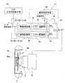
- FIG. 1 is a partially cutaway longitudinal sectional view showing a conceptual configuration of a controller device for an electric vehicle according to a first embodiment of the present invention, a motor, a reducer, a wheel bearing, and a wheel.
- FIG. 15 is a partially enlarged view of FIG. 14. It is a partial notch longitudinal cross-sectional view which shows the conceptual structure of the conventional controller apparatus for electric vehicles, a motor, a reduction gear, the wheel bearing, and a wheel.
- FIG. 1 shows the periphery of one wheel W of an electric vehicle.
- a wheel bearing A that rotatably supports the wheel W, a motor B, and a speed reducer C that decelerates the rotation of the motor B and transmits it to the inner member 2 that is a rotating wheel of the wheel bearing A.
- It constitutes an in-wheel motor drive device that is a combined assembly.
- the wheel W is fitted with a tire T.
- a brake disc 49 a of the brake 49 is attached to the inner member 2 of the wheel bearing A together with the wheel W.
- the motor B of the in-wheel motor drive device is driven by the electric vehicle controller device 51.
- the motor B includes a synchronous motor driven by a three-phase current. Specific examples of the in-wheel motor drive device will be described later with reference to FIGS.
- the electric vehicle controller device 51 is a device that controls the motor B in accordance with a motor drive command a given from an electric control unit (ECU) 52 serving as a higher-level control means.
- ECU electric control unit
- a plurality of (two in the illustrated example) controllers 53 that are in use are included.
- the electric control unit 52 has a function of outputting the motor drive command a in accordance with an operation amount of an accelerator (not shown) of the automobile.
- the electric control unit 52 may correct the operation amount of the accelerator and output the motor drive command a by an antilock brake system, an attitude control system, or the like.
- Each controller 53 is composed of a control circuit section 54 of a weak electric circuit and a power circuit section 55 mainly composed of a high electric circuit.
- the power circuit unit 55 is a motor of each phase motor coil (not shown) for generating a rotating magnetic field of the motor B from DC current supplied from a battery (not shown) according to a command from the control circuit unit 54. It is an inverter circuit that converts the drive current and applies it to the motor B, and is mainly composed of power circuit elements such as switching transistors.
- the power circuit unit 54 includes a PWM driver (not shown) that efficiently drives an internal transistor, and a motor driving current chopped by the PWM driver is applied to the motor B.
- the control circuit unit 53 is a low-power circuit that controls the power circuit unit 55 in response to a motor drive command a given from an electric control unit (ECU) 52 serving as a higher-level control unit.
- the control circuit unit 53 is responsible for calculating a current value to be passed to the motor, its timing, etc. in response to a command from the electric control unit (ECU) 52, and giving a command to the power circuit unit 55. It is a means for performing various controls such as speed feedback control.
- the PWM driver may be provided in the control circuit unit 53 instead of being provided in the power circuit unit 55.
- the electric vehicle controller device 51 includes a plurality of controllers 53 having the functions as described above, and an abnormality determination unit 56 that determines abnormality of the controller 53 in use according to a predetermined rule and generates a switching signal c.
- an abnormality determination unit 56 that determines abnormality of the controller 53 in use according to a predetermined rule and generates a switching signal c.
- external and internal switching means 57, 58 for switching the controller in a state of functioning with respect to the motor B.
- the external switching means 57 is provided on the external output side of the controller 53 and switches the controller connected to the motor B in response to the switching signal c.
- the switching means 58 on the internal side is provided inside the controller 53, and the controller 53 is in an active state in response to the switching signal c, that is, a state where it can be operated when the power is turned on, and a stop state. For example, it is means for switching to an inoperable state when the power is shut off.
- the abnormality determination means 56 is a means for determining an abnormality in the control circuit unit 54 and the power circuit unit 55. When it is determined that either the control circuit unit 54 or the power circuit unit 55 is abnormal, a switching signal c is output. To do. In the abnormality determination, in addition to the determination of the failure, it is also possible to determine that the light abnormality that has not reached the failure is abnormal. For example, for the control circuit unit 54, the control circuit unit 54 is compared with the input of the control circuit unit 54 and the detected value of the rotational speed of the motor B or the motor current, and the case where it is not within a predetermined range is determined as abnormal To do. The above defined range may be determined arbitrarily. The abnormality determination of the power circuit unit 55 compares the input of the power circuit unit 55 with the detected value of the rotation speed of the motor B or the motor current, and determines that it is not within a predetermined range as an abnormality.
- the external switching means 57 is composed of a switching circuit or the like that switches the connection between the output terminal of the power circuit section 55 and each input terminal of the motor B between the plurality of controllers 53 in response to the switching signal c. That is, the external switching unit 57 is a switching unit that switches the connection of one output-side contact SC to the two input-side contacts SA and SB.
- the switching unit 58 on the internal side connects the power source for the control circuit unit 54 or the motor driving battery that serves as the power source for the power circuit unit 55 to only the controller 53 to be used among the controllers 53, and the switching signal It is assumed that the controller 53 to be switched to the power supply state is switched at c. It should be noted that the internal switching means 58 is not provided, and the control circuit unit 53 of each controller 53 is always connected with a power supply (not shown) and always outputs a motor drive command a output from the electric control unit 52. You may make it input and make it be in a standby state. The power circuit unit 55 is always connected to the battery at the input terminal, but may not output current while the output terminal is disconnected by the switching means 57.
- the controller 53 having a power circuit unit 55 and a control circuit unit 54 is provided with a plurality of selectively used controllers, and the controller 63 being used is abnormal such as a failure.
- the controller 53 being used is switched to another controller 53. Therefore, reliability is improved.
- the failure of a motor for driving a vehicle and a controller for controlling the motor is fatal, and it is used in an environment where there are many failure factors such as electromagnetic noise, electrostatic noise and vibration.
- reliability can be ensured by a redundant configuration including a plurality of controllers.
- control circuit unit 54 of the plurality of controllers 53 when the control circuit unit 54 of the plurality of controllers 53 is always turned on and is in a standby state by inputting a motor drive command a, the motor can be controlled by switching immediately when an abnormality occurs. It is possible to switch without causing a time lag where the control is impossible or the drive is stopped.
- FIG. 2 to 12 show an electric vehicle controller device 51 according to second to twelfth embodiments. Each of these embodiments has the same configuration as that of the first embodiment shown in FIG.
- an input side switching means 59 and an output side switching means 57 serving as external switching means are provided as switching means that operate in response to the switching signal c.
- the input side switching unit 59 includes a switching circuit that switches the input of the motor driving current a to the input terminal of the control circuit unit 54 for the two controllers 53 in response to the switching signal c.
- the output side switching means 57 includes a switching circuit that switches the output terminal of the power circuit unit 55 connected to the motor B for the two controllers 53 in response to the switching signal c.
- Each controller 53 is provided with the internal switching means 58.
- Other configurations are the same as those of the first embodiment shown in FIG. When the switching means 59 and 57 are provided on both the input side and the output side in this way, the controller 53 that is not in use is completely disconnected from the input and output, and the operation is more reliable.
- the input side switching means 59 and the internal side switching means 58 are provided as the switching means operated by the switching signal c.
- the input side switching unit 59 includes a switching circuit that switches the input of the motor driving current a to the input terminal of the control circuit unit 54 for the two controllers 53 in response to the switching signal c.
- the internal switching means 58 is a means having the aforementioned function.
- Other configurations are the same as those of the first embodiment shown in FIG. In the case of this configuration, when the switching signal c due to abnormality detection is output, the controller 53 that is in a state of functioning with respect to the motor B is switched by switching the input side switching means 59.
- the internal switching means 58 is provided as the switching means operated by the switching signal c.
- Other configurations are the same as those of the first embodiment shown in FIG. In the case of this configuration, when the switching signal c due to abnormality detection is output, the controller 53 connected to the power source and in an active state is switched by the function of the switching means 58 on the internal side. As a result, the controller 53 that controls the motor B is switched.
- one controller 53 is provided, and two control circuit units 54 for controlling the power circuit unit 55 in the controller 53 are provided so as to be selectively usable.
- an input-side switching unit 59 and an intermediate-side switching unit 60 are provided as switching units that operate according to the switching signal c.
- the switching means 59 on the input side includes a switching circuit that switches the input of the motor driving current a to the two control circuit portions 54 of the controller 53 in response to the switching signal c.
- the switching unit 60 on the intermediate side includes a switching circuit that switches the output terminals of the two control circuit units 54 to the input terminals of the power circuit unit 55 in response to the switching signal c.
- the controller 53 is provided with an internal switching means 58A.
- the control circuit unit 54 used in the event of an abnormality preferably has a circuit configuration mainly composed of an analog circuit resistant to electromagnetic noise. Other configurations in this embodiment are the same as those in the first embodiment shown in FIG.
- the switching means 59 on the input side is switched, so that the control circuit unit 54 to which the motor drive command a is input is switched. Further, in response to the switching signal c, the contacts SA and SB on the input side of the switching means 60 on the intermediate side are switched, and the control circuit unit 54 to which the motor drive command a is input is connected to the power circuit unit 55. Become. In response to the switching signal c, the internal switching unit 58A switches the control circuit unit 54 to be activated, for example, the control circuit unit 54 that turns on the power.
- the sixth embodiment shown in FIG. 6 omits the switching means 59 on the input side in the fifth embodiment shown in FIG. 5 so that the motor drive command a is always input to both control circuit units 54. It is a thing.
- Other configurations are the same as those of the fifth embodiment shown in FIG.
- the fifth embodiment shown in FIG. 5 is provided with various switching means 59, 60, 58A in order to further ensure the operation, but has a configuration in which some of the switching means are omitted as shown in FIG. Even in this case, it is possible to control by switching the control circuit unit 54 in response to the switching signal c.
- the seventh embodiment shown in FIG. 7 is different from the fifth embodiment shown in FIG. 5 in that the intermediate switching means 60 is omitted, and the output terminals of the two control circuit units 54 are connected to the normal power circuit unit 55. It is as a state.
- Other configurations are the same as those of the fifth embodiment shown in FIG. Also in this configuration, since the control circuit unit 54 to which the motor drive command a is input is switched in response to the switching signal c, the control circuit unit 54 used at the time of abnormality can be changed.
- the eighth embodiment shown in FIG. 8 is different from the fifth embodiment shown in FIG. 5 in that the input side and intermediate side switching means 59 and 60 are omitted and only the internal side switching means 58A is provided. .
- Other configurations are the same as those of the fifth embodiment shown in FIG.
- the switching means 58A is provided in each control circuit unit 54. In the case of this configuration, in response to the switching signal c, the control circuit unit 54 to be used is switched by switching the control circuit unit 54 in the active state, that is, the power supply is turned on.
- one controller 53 is provided, and two power circuit portions 55 in the controller 53 are provided so as to be selectively usable.
- the switching means that operates in response to the switching signal c
- an intermediate-side switching means 60 includes a switching circuit that switches the output terminal of the control circuit unit 54 with respect to the input terminals of the two power circuit units 55 in response to the switching signal c.
- the output-side switching means 57 includes a switching circuit that switches connections between the output terminals of the plurality of power circuit units 55 and the input terminals of the motor B in response to the switching signal c.
- the internal switching means 58A of this embodiment switches the power circuit unit 55 connected to the battery in response to the switching signal c.
- control circuit unit 54 connected to the power circuit unit 55 is switched by switching the intermediate switching unit 60 in response to the switching signal c.
- the output-side switching means 57 switches the power circuit unit 55 connected to the motor B.
- the internal switching unit 58A switches the power circuit unit 55 connected to the battery in response to the switching signal c.
- the tenth embodiment shown in FIG. 10 omits the switching means 60 on the intermediate side with respect to the ninth embodiment shown in FIG. 9, and the output terminals of the two control circuit units 54 are connected to the normal power circuit unit 55. It is as a state.
- Other configurations are the same as those of the embodiment of FIG. Also in this configuration, the power circuit unit 55 connected to the motor B is switched by the output-side switching unit 57 in response to the switching signal c.
- the eleventh embodiment shown in FIG. 11 omits the switching means 57 on the output side, and the output ends of the two power circuit sections 55 are always connected to the motor B as compared with the ninth embodiment shown in FIG. It is as a state.
- Other configurations are the same as those of the ninth embodiment shown in FIG. Also in this configuration, the power circuit unit 55 to which the control circuit unit 54 is connected is switched by the intermediate switching unit 60 in response to the switching signal c. Therefore, the motor B is driven by the switched power circuit unit 55.
- an abnormality such as a failure occurs in the power circuit unit 55 in use, normal motor drive can be continued using another power circuit unit 55.
- FIG. 13 shows an in-wheel in which a reduction gear C is interposed between a wheel bearing A and a motor B of a vehicle, and a hub supported by the wheel bearing A and an output shaft 24 of the motor B are connected coaxially.
- a motor drive device is shown.
- the wheel bearing A, the motor B, and the speed reducer C constitute an in-wheel motor assembly U that is unitized as one assembly part.
- the wheel bearing A is fixed to the vehicle body via a suspension device (not shown) such as a knuckle on the outer periphery of the housing 33b of the reduction gear C or the housing 22 of the motor B.
- the motor B is driven by the electric vehicle controller device 51.
- Reduction gear C has a reduction ratio of 5 times or more, and preferably has a reduction ratio of 8 times or more.
- the speed reducer C is a cycloid speed reducer, in which eccentric portions 32a and 32b are formed on an input shaft 32 coaxially connected to the output shaft 24 of the motor B, and bearings 35 are provided on the eccentric portions 32a and 32b, respectively.
- the curved plates 34a and 34b are attached to the wheel bearings A to transmit the eccentric motion of the curved plates 34a and 34b to the wheel bearing A as rotational motion.
- the rotation of the motor B is the eccentric motion of the curved plates 34a, 34b, and the cycloid speed reducer that transmits this eccentric motion to the hub as the rotational motion is a compact speed reduction that provides a large reduction ratio.
- the machine C and the reduction gear C can be compactly designed with a compact arrangement structure, and a large reduction ratio of 1/10 or more can be obtained in one stage.
- the wheel bearing A is a third generation inner ring rotation type hub bearing in which the inner member 2 forming the rolling surface of the bearing constitutes a hub.
- the wheel bearing A includes an outer member 1 having a double row rolling surface 3 formed on the inner periphery, an inner member 2 having a rolling surface 4 facing each of the rolling surfaces 3, and these outer members 1. It is comprised by the double row rolling element 5 interposed between the rolling surfaces 3 and 4 of the direction member 1 and the inner member 2. As shown in FIG.
- the inward member 2 also serves as a hub for attaching the vehicle wheel.
- the wheel bearing A is a double-row angular ball bearing type, and the rolling elements 5 are formed of balls and are held by a cage 6 for each row.
- the rolling surfaces 3 and 4 are arc-shaped in cross section, and each rolling surface 3 and 4 is formed so that the contact angle is outward.
- the outboard side end of the bearing space between the outer member 1 and the hub 2 is sealed with a seal member 7.
- the outer member 1 is a stationary raceway, and has a flange 1a attached to an outboard side housing 33b of the housing 33 of the speed reducer C on the outer periphery, and the whole is an integral part. .
- the flange 1a is provided with bolt insertion holes 14 at a plurality of locations in the circumferential direction.
- the housing 33b is provided with a bolt screw hole 44 whose inner periphery is threaded at a position corresponding to the bolt insertion hole 14.
- the outer member 1 is attached to the housing 33b by screwing the attachment bolt 15 inserted into the bolt insertion hole 14 into the bolt screw hole 44.
- the inboard member 2 includes an outboard side member 9 having a hub flange 9a for attaching a wheel (not shown), and the outboard side is fitted to the inner periphery of the outboard side member 9 so that the outboard is swaged.
- the inboard side material 10 is integrated with the side material 9.
- column is formed in these outboard side materials 9 and inboard side materials 10.
- FIG. A through hole 11 is provided at the center of the inboard side member 10.
- the hub flange 9a is provided with insertion holes 17 for hub bolts 16 at a plurality of locations in the circumferential direction.
- the motor B is a radial gap type in which a radial gap is provided between a stator 23 fixed to a cylindrical housing 22 and a rotor 25 attached to an output shaft 24.
- the output shaft 24 is cantilevered by two bearings 26 on the cylindrical portion of the housing 33a on the inboard side of the speed reducer C.
- the inboard side end of the gap between the output shaft 24 and the housing 33 a is sealed with the seal member 20.
- a cooling medium flow path 45 is provided in the peripheral wall portion of the housing 22 over the entire circumference.
- a cooling medium made of oil or a water-soluble coolant is circulated in the cooling medium flow path 45 by a supply driving source (not shown) such as a pump.
- the speed reducer C is a cycloid speed reducer as described above, and two curved plates 34a and 34b formed with wavy trochoidal curves having a gentle outer shape as shown in FIG. It is attached to each of the 32 eccentric parts 32a and 32b.
- a plurality of outer pins 36 for guiding the eccentric motion of each of the curved plates 34a, 34b on the outer peripheral side are provided across the housing 33b, and a plurality of inner pins 38 attached to the inboard side member 10 of the inner member 2 are provided.
- the curved plates 34a and 34b are engaged with a plurality of circular through holes 39 provided in the inserted state.
- the input shaft 32 is spline-coupled with the output shaft 24 of the motor B and rotates integrally.
- the input shaft 32 is supported at both ends by two bearings 40 on the housing 33a on the inboard side and the inner diameter surface of the inboard side member 10 of the inner member 2.
- the reduction gear C is located within the wheel W, that is, within the range of the width E of the wheel W, and does not protrude from the wheel W in the direction of the wheel axis O.
- the curved plates 34a and 34b attached to the input shaft 32 that rotates together with the motor B perform an eccentric motion.
- the eccentric motions of the curved plates 34 a and 34 b are transmitted to the inner member 2 as rotational motion by the engagement of the inner pins 38 and the through holes 39.
- the rotation of the inner member 2 is decelerated with respect to the rotation of the output shaft 24.
- the two curved plates 34a and 34b are mounted on the eccentric portions 32a and 32b of the input shaft 32 so that the vibrations caused by the eccentric motion are canceled out from each other, and are mounted on both sides of the eccentric portions 32a and 32b.
- bearings 42, 43 are mounted on the outer pins 36 and the inner pins 38, and outer rings 42a, 43a of these bearings 42, 43 are respectively connected to the curved plates 34a, 34b. It is in rolling contact with the outer periphery and the inner periphery of each through-hole 39. Therefore, the contact resistance between the outer pin 36 and the outer periphery of each curved plate 34a, 34b and the contact resistance between the inner pin 38 and the inner periphery of each through hole 39 are reduced, and the eccentric motion of each curved plate 34a, 34b is smooth. Can be transmitted to the inner member 2 as a rotational motion.
Landscapes
- Engineering & Computer Science (AREA)
- Transportation (AREA)
- Mechanical Engineering (AREA)
- Power Engineering (AREA)
- Automation & Control Theory (AREA)
- Sustainable Energy (AREA)
- Life Sciences & Earth Sciences (AREA)
- Sustainable Development (AREA)
- Human Computer Interaction (AREA)
- Electric Propulsion And Braking For Vehicles (AREA)
- Control Of Electric Motors In General (AREA)
- Valves And Accessory Devices For Braking Systems (AREA)
- Connection Of Motors, Electrical Generators, Mechanical Devices, And The Like (AREA)
- Arrangement Or Mounting Of Propulsion Units For Vehicles (AREA)
Abstract
コントローラに冗長性を持たせ、コントローラの故障など異常発生時にも、モータの制御が適切に行えて、信頼性を高めることのできる電気自動車用コントローラ装置を提供する。モータ(B)の駆動電流を出力するパワー回路部(55)、および上位の制御手段から与えられるモータ駆動指令(a)に応答してパワー回路部(55)の制御を行う弱電回路の制御回路部(54)を有するコントローラ(53)を複数備える。使用中のコントローラ(53)の異常を判定して切替信号(c)を生成する異常判定手段(56)を設ける。その切替信号(c)に応答して、モータ(B)に対して機能する状態にあるコントローラ(53)を切り替える切替手段(57,58)を設ける。コントローラ(53)は、一つとし、制御回路部(54)またはパワー回路部(55)を複数設けて切り替えるようにしても良い。
Description
本出願は、2010年3月26日出願の特願2010-072057の優先権を主張するものであり、その全体を参照により本願の一部をなすものとして引用する。
この発明は、電気自動車におけるモータ駆動用のコントローラ装置に関し、コントローラまたは内蔵される構成要素を複数個持つことで冗長性を図った電気自動車用コントローラ装置に関する。
電気自動車には、モータのみで駆動され、またはモータと内燃機関とを併用するハイブリッド形式のものなど、各種のものがある。このような電気自動車におけるモータの設置形式としては、個々の車輪毎にモータを設けるインホイールモータ形式や、車体に搭載したモータを、ディファレンシャルを介して分配する形式のものなどがある。いずれのモータ設置形式の場合であっても、ハンドルやアクセル等の情報からモータ駆動指令を生成する上位制御手段の他に、制御回路部およびパワー回路部を有するコントローラが設けられる。
モータの設置形式がインホイールモータ形式である場合を例に説明する。図16は、従来のインホイールモータ駆動装置を示し、ホイールWを回転自在に支持する車輪用軸受Aと、モータBと、このモータBの回転を減速して車輪用軸受Aの回転輪である内方部材2に伝達する減速機Cとが互いに結合され、アセンブリであるインホイールモータ駆動装置が構成されている。モータBは、電気制御ユニット(ECU)等から出力されるモータ駆動指令aにより、コントローラ53を介して制御される。コントローラ53は、弱電回路である制御回路部54と、強電回路であるパワー回路部55とでなる。
電気自動車では車両駆動のためのモータBおよびこれを制御するコントローラ53の故障は致命的である。特に電気自動車では、モータBの駆動トルクが大きくモータ自身からの電磁ノイズは大きい。さらに、電気自動車走行時には、外部から多くの電磁ノイズや静電ノイズを受ける可能性が高い。しかも、そのコントローラ53は車載のため、常に加振された過酷な環境下で使用される。
電気自動車のモータ制御は、通常、マイコンを使って行う方式を採るが、万が一、このマイコンに上述した電磁ノイズもしくは静電ノイズが影響を及ぼした場合には、コントローラ53自体が正常に動作できないばかりでなく、モータBを動かせなくなる可能性がある。特に、電気自動車の駆動源であるモータBを、高い減速比を有する減速機Cを介してホイールWにトルク伝達する場合、モータ制御の不安定化を原因としたモータBのトルク変動は拡大されてタイヤのホイールWのトルク変動を引き起こすため、このモータBを制御するコントローラ53の信頼性は重要となる。
この発明の目的は、コントローラに冗長性を持たせ、コントローラの故障などの異常発生時にも、モータの制御が適切に行えて、信頼性を高めることのできる電気自動車用コントローラ装置を提供することである。
この発明の第1構成にかかる電気自動車用コントローラ装置は、電気自動車を駆動するモータのコントローラ装置であって、モータの駆動電流を出力するパワー回路部、および上位の制御手段から与えられるモータ駆動指令に応答して前記パワー回路部の制御を行う弱電回路の制御回路部を有するコントローラを複数備え、定められた規則により使用中のコントローラの異常を判定して切替信号を生成する異常判定手段と、この異常判定手段の出力する切替信号に応答して、モータに対して機能する状態にあるコントローラを切り替える切替手段を設けたものである。なお、モータに対して機能する状態にあるコントローラを切り替えるという機能は、前記切替信号に応答してモータに対し接続状態にあるコントローラを切り替える機能としても、能動状態、つまり電源が投入されて動作可能な状態にあるコントローラを前記切替信号に応答して切り替える機能であっても、その両方であっても良い。
この構成によると、それぞれパワー回路部および制御回路部を有し選択的に使用されるコントローラを複数備え、使用中のコントローラが故障等の異常であると判定されたときに、使用中のコントローラが別のコントローラに切替えられる。そのため、信頼性が高められる。電気自動車では車両駆動のためのモータおよびこれを制御するコントローラの故障は致命的であり、しかも電磁ノイズや静電ノイズや振動等の作用する故障要因の多い環境化で使用されるが、上記のようにコントローラを複数備える冗長構成により、信頼性が確保できる。
前記第1構成において、前記複数のコントローラの前記制御回路部は、常に電源を投入しかつ前記モータ駆動指令を入力してスタンバイ状態にしておき、前記異常判定手段が、使用中のコントローラが異常であると判定して切替信号を出力したときに、切替手段が別のコントローラをモータに対して機能する状態とするものであっても良い。なお、この明細書で言う「スタンバイ状態」は、切替えられると瞬時に動作可能となる状態を言う。
このように予備のコントローラの制御回路部を常にスタンバイ状態にしておくことで、異常発生時に即座に切替えてモータ制御ができて、モータが制御不能または駆動停止状態となるタイムラグをできるだけ無くして切り替えることができる。
このように予備のコントローラの制御回路部を常にスタンバイ状態にしておくことで、異常発生時に即座に切替えてモータ制御ができて、モータが制御不能または駆動停止状態となるタイムラグをできるだけ無くして切り替えることができる。
この発明の第2構成にかかる電気自動車用コントローラ装置は、電気自動車を駆動するモータのコントローラ装置であって、モータの駆動電流を出力するパワー回路部、および上位の制御手段から与えられるモータ駆動指令に応答して前記パワー回路の制御を行う弱電回路の制御回路部を有するコントローラを備え、前記コントローラは、前記制御回路部として、同じパワー回路部に対して選択的に使用される複数の制御回路部を有し、定められた規則により使用中の制御回路部の異常を判定して切替信号を生成する異常判定手段と、この異常判定手段の出力する切替信号に応答して、前記パワー回路部に対して機能する状態にある別の制御回路部に切り替える切替手段を設けたものである。なお、この場合も、前記パワー回路部に対して機能する状態にある制御回路部を切り替えるという機能は、前記切替信号に応答してパワー回路部に対して接続状態にある制御回路部を切り替える機能としても、能動状態にある制御回路部前記切替信号に応答して切り替える機能であっても、その両方であっても良い。
この構成によると、使用中のコントローラの制御回路部が故障等の異常であると判定されたときに、使用中の制御回路部が別の制御回路部に切替えられる。そのため、信頼性が高められる。この構成の場合、冗長構成とするのは弱電回路である制御回路部のみであるため、コントローラの全体を複数持つ場合と比べて、低コストで信頼性を高める冗長構成とできる。
この構成の場合に、複数個の制御回路部のうち、異常時に使用される前記別の制御回路部は、電磁ノイズに耐性を有するアナログ回路を主とする回路構成としても良い。電磁ノイズに耐性を有するアナログ回路を主とする回路構成であると、車両が電磁ノイズの大きな環境で走行していて制御回路部の異常が発生した場合に、切替え後に同様な異常を再発することが抑制され、信頼性がより一層高められる。
前記構成において、制御回路部を複数持つ冗長構成とする場合に、前記複数の制御回路部には常に電源を投入してスタンバイ状態にしておき、前記異常判定手段が、使用中の制御回路部が異常であると判定して切替信号を出力したときに、切替手段が前記別の制御回路部をモータに接続状態としても良い。この場合も、異常発生時に即座に切替えてモータ制御ができて、モータが制御不能または駆動停止状態となるタイムラグをできるだけ無くして切り替えることができる。
この発明の第3構成にかかる電気自動車用コントローラ装置は、電気自動車を駆動するモータのコントローラ装置であって、モータの駆動電流を出力するパワー回路部、および上位の制御手段から与えられるモータ駆動指令に応答して前記パワー回路部の制御を行う弱電回路の制御回路部を有するコントローラを備え、前記コントローラは、前記パワー回路部として、同じ制御回路部により制御されて選択的に使用される複数のパワー回路部を有し、定められた規則により使用中のパワー回路部の異常を判定して切替信号を生成する異常判定手段と、この異常判定手段の出力する切替信号に応答して、前記前記モータに対し機能するする状態にあるパワー回路部を切り替える切替手段を設けたものである。なお、この場合も、前記モータに対して機能する状態にあるパワー回路部を切り替えるという機能は、前記切替信号に応答してモータに対して接続状態にあるパワー回路部を切り替える機能としても、能動状態にあるパワー回路部を前記切替信号に応答して切り替える機能であっても、その両方であっても良い。
この構成によると、使用中コントローラのパワー回路部が故障等の異常であると判定されたときに、使用中のパワー回路部が別のパワー回路部に切替えられる。そのため、信頼性が高められる。この構成の場合、冗長構成とするのはパワー回路部のみであるため、コントローラの全体を複数持つ場合と比べて、低コストで冗長構成とできる。
第1~第3構成のそれぞれにおいて、前記モータは、8以上の減速比を有する減速機を介して自動車のホイールにトルク伝達するものであっても良い。前記減速機はサイクロイド減速機であっても良い。高い減速比を有する減速機を介してホイールにトルク伝達する場合、モータ制御の不安定化を原因としたモータのトルク変動は拡大されてタイヤのホイールのトルク変動を引き起こすため、モータのコントローラの信頼性は重要となる。そのため、この発明の冗長構成が効果的に発揮される。
前記モータが、8以上の減速比を有する減速機を介して自動車のホイールにトルク伝達するものである場合に、前記減速機とモータと車輪用軸受とが互いに結合されたアセンブリであるインホイールモータ駆動装置を構成し、前記減速機がホイール内に位置するものであっても良い。
この発明は、添付の図面を参考にした以下の好適な実施形態の説明から、より明瞭に理解されるであろう。しかしながら、実施形態および図面は単なる図示および説明のためのものであり、この発明の範囲を定めるために利用されるべきものではない。この発明の範囲は添付の請求の範囲によって定まる。添付図面において、複数の図面における同一の符号は、同一または相当する部分を示す。
この発明の第1実施形態に係る電気自動車用コントローラ装置の概念構成と、モータ、減速機、車輪用軸受、およびホイールを示す一部切欠縦断面図である。
この発明の第2実施形態に係る電気自動車用コントローラ装置の概念構成を示すブロック図である。
この発明の第3実施形態に係る電気自動車用コントローラ装置の概念構成を示すブロック図である。
この発明の第4実施形態に係る電気自動車用コントローラ装置の概念構成を示すブロック図である。
この発明の第5実施形態に係る電気自動車用コントローラ装置の概念構成を示すブロック図である。
この発明の第6実施形態に係る電気自動車用コントローラ装置の概念構成を示すブロック図である。
この発明の第7実施形態に係る電気自動車用コントローラ装置の概念構成を示すブロック図である。
この発明の第8実施形態に係る電気自動車用コントローラ装置の概念構成を示すブロック図である。
この発明の第9実施形態に係る電気自動車用コントローラ装置の概念構成を示すブロック図である。
この発明の第10実施形態に係る電気自動車用コントローラ装置の概念構成を示すブロック図である。
この発明の第11実施形態に係る電気自動車用コントローラ装置の概念構成を示すブロック図である。
この発明の第12実施形態に係る電気自動車用コントローラ装置の概念構成を示すブロック図である。
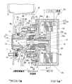
上記各実施形態の電気自動車用コントローラ装置が使用されるモータ、減速機、および車輪用軸受のアセンブリを示す縦断面図である。
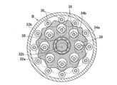
同減速機の部分横断面図である。
図14の一部拡大図である。
従来の電気自動車用コントローラ装置の概念構成と、モータ、減速機、車輪用軸受、およびホイールを示す一部切欠縦断面図である。
この発明の第1実施形態を図1と共に説明する。図1は電気自動車の一つのホイールWの周辺を示す。ホイールWを回転自在に支持する車輪用軸受Aと、モータBと、このモータBの回転を減速して車輪用軸受Aの回転輪である内方部材2に伝達する減速機Cとが、互いに結合されたアセンブリであるインホイールモータ駆動装置を構成している。ホイールWはタイヤTが嵌められている。車輪用軸受Aの内方部材2には、ホイールWと共にブレーキ49のブレーキディスク49aが取付けてある。上記インホイールモータ駆動装置のモータBが、電気自動車用コントローラ装置51により駆動される。モータBは、3相電流で駆動される同期モータ等からなる。インホイールモータ駆動装置の具体例は、図13~図15と共に後述する。
この電気自動車用コントローラ装置51は、上位の制御手段となる電気制御ユニット(ECU)52から与えられるモータ駆動指令aに応じてモータBを制御する装置であり、この実施形態では、互いに選択的に使用状態とされる複数(図示の例では2つ)のコントローラ53を有している。電気制御ユニット52は、自動車のアクセル(図示せず)の操作量に応じて前記モータ駆動指令aを出力する機能を備える。電気制御ユニット52は、アンチロックブレーキシステム、姿勢制御システム等により、前記アクセルの操作量を補正して前記モータ駆動指令aを出力するものであっても良い。
各コントローラ53は、弱電回路の制御回路部54と主に強電回路からなるパワー回路部55とで構成される。パワー回路部55は、バッテリ(図示せず)から給電される直流電流を、制御回路部54の指令に従い、モータBの回転磁界を発生させるための各相のモータコイル(図示せず)のモータ駆動電流に変換してモータBに印加するインバータ回路であり、スイッチングトランジスタ等のパワー回路素子によって主に構成される。パワー回路部54は、内部のトランジスタを効率良く駆動するPWMドライバ(図示せず)を有し、このPWMドライバによりチョッピングされたモータ駆動電流がモータBに印加される。
制御回路部53は、上位の制御手段となる電気制御ユニット(ECU)52から与えられるモータ駆動指令aに応答してパワー回路部55の制御を行う弱電回路である。制御回路部53は、電気制御ユニット(ECU)52の指令に対応して、モータに流すべき電流値やそのタイミング等を計算し、パワー回路部55に対し指令を与える役目を担っていて、回転速度のフィードバック制御を行うなどの各種の制御を行う手段である。なお、上記のPWMドライバは、パワー回路部55に設ける代わりに、制御回路部53に設けても良い。
この電気自動車用コントローラ装置51は、上記のような機能を有するコントローラ53を複数備え、かつ定められた規則により使用中のコントローラ53の異常を判定して切替信号cを生成する異常判定手段56と、この異常判定手段56の出力する切替信号cに応答して、モータBに対して機能する状態にあるコントローラを切り替える外部側および内部側の切替手段57,58が設けられている。外部側の切替手段57は、コントローラ53の外部の出力側に設けられたものであって、前記切替信号cに応答して、モータBに対して接続状態にあるコントローラを切り替える。内部側の切替手段58は、コントローラ53の内部に設けられたものであって、コントローラ53を、前記切替信号cに応答して能動状態、つまり電源が投入されて動作可能な状態と、停止状態、例えば電源が遮断されて動作不能な状態とに切り替える手段である。
異常判定手段56は、制御回路部54およびパワー回路部55の異常判定を行う手段であり、制御回路部54およびパワー回路部55のいずれかに異常がある、と判定すると、切替信号cを出力する。異常判定は、故障の判定の他に、故障にまでは達していない軽度の異常に対しても、異常であると判定を行うものとしても良い。この異常判定は、例えば、制御回路部54については、制御回路部54の入力とモータBの回転速度またはモータ電流の検出値などとを比較し、定められた範囲内にない場合を異常として判定する。上記の定められた範囲は、任意に定めれば良い。パワー回路部55の異常判定は、このパワー回路部55の入力とモータBの回転速度またはモータ電流の検出値などとを比較し、定められた範囲内にない場合を異常として判定する。
外部側の切替手段57は、切替信号cに応答し、複数のコントローラ53の間で、パワー回路部55の出力端子とモータBの各入力端子との接続を切り換えるスイッチング回路等からなる。すなわち、外部側の切替手段57は、入力側の2つの接点SA,SBに対して出力側の一つの接点SCの接続を切り替えるスイッチング手段である。
内部側の切替手段58は、例えば、各コントローラ53のうち、使用するコントローラ53のみに制御回路部54用の電源やパワー回路部55の電源となるモータ駆動用バッテリを接続状態とし、前記切替信号cでその電源接続状態とするコントローラ53を切り替えるものとされる。なお、内部側の切替手段58を設けず、各コントローラ53の制御回路部53は、常に電源(図示せず)を接続して投入し、かつ常に電気制御ユニット52の出力するモータ駆動指令aを入力してスタンバイ状態にしておくようにしても良い。また、パワー回路部55についても、常に、入力端子をバッテリに接続してあるが、出力端子が切替手段57で切り離された状態である間は、電流を出力しないものとしても良い。
この構成の電気自動車用コントローラ装置51によると、それぞれパワー回路部55および制御回路部54を有し選択的に使用されるコントローラ53を複数備え、使用中のコントローラ63が故障等の異常であると判定されたときに、使用中のコントローラ53が別のコントローラ53に切替えられる。そのため、信頼性が高められる。電気自動車では車両駆動のためのモータおよびこれを制御するコントローラの故障は致命的であり、しかも電磁ノイズや静電ノイズや振動等の作用する故障要因の多い環境化で使用されるが、上記のようにコントローラを複数備える冗長構成により、信頼性が確保できる。また、前記複数のコントローラ53の制御回路部54につき、常に電源を投入しかつモータ駆動指令aを入力してスタンバイ状態にした場合は、異常発生時に即座に切替えてモータ制御ができて、モータが制御不能または駆動停止状態となるタイムラグをできるだけ無くして切り替えることができる。
図2~図12は、第2~第12実施形態に係る電気自動車用コントローラ装置51を示す。これらの各実施形態において、特に説明した事項の他は図1に示す第1実施形態と同様の構成である。
図2に示す第2実施形態では、切替信号cによって動作する切替手段として、外部側の切替手段となる入力側の切替手段59と出力側の切替手段57とが設けられている。入力側切替手段59は、切替信号cに応答して、2つのコントローラ53に対して制御回路部54の入力端子へのモータ駆動電流aの入力を切り替えるスイッチング回路からなる。出力側切替手段57は、切替信号cに応答して、2つのコントローラ53に対してモータBに接続するパワー回路部55の出力端子を切り替えるスイッチング回路からなる。また、各コントローラ53に前記内部側の切替手段58が設けられている。その他の構成は図1に示す第1実施形態と同様である。このように入力側と出力側の両方に切替手段59,57を設けた場合は、使用状態にないコントローラ53が入力と出力から完全に切り離され、動作がより確実となる。
図3に示す第3実施形態では、切替信号cによって動作する切替手段として、入力側切替手段59と、前記内部側の切替手段58とを設けている。入力側切替手段59は、切替信号cに応答して、2つのコントローラ53に対して制御回路部54の入力端子へのモータ駆動電流aの入力を切り替えるスイッチング回路からなる。内部側の切替手段58は前述の機能を持つ手段である。その他の構成は図1に示す第1実施形態と同様である。この構成の場合、異常検出による切替信号cが出力されると、入力側切替手段59を切り替えることで、モータBに対して機能する状態にあるコントローラ53が切り替えられる。
図4に示す第4実施形態では、切替信号cによって動作する切替手段として、前記内部側の切替手段58のみを設けている。その他の構成は図1に示す第1実施形態と同様である。この構成の場合、異常検出による切替信号cが出力されると、内部側の切替手段58の機能により、電源と接続されて能動状態にあるコントローラ53が切り替わる。これにより、モータBを制御するコントローラ53が切り替わることになる。
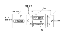
図5に示す第5実施形態では、コントローラ53を一つとし、このコントローラ53におけるパワー回路部55を制御する制御回路部54を、選択的に使用可能に2個設けている。また、切替信号cによって動作する切替手段として、入力側の切替手段59と中間側の切替手段60とが設けられている。入力側の切替手段59は、切替信号cに応答して、コントローラ53の2つの制御回路部54に対してモータ駆動電流aの入力を切り替えるスイッチング回路からなる。中間側の切替手段60は、切替信号cに応答して、2つの制御回路部54の出力端子を、パワー回路部55の入力端子に対して切り替えるスイッチング回路からなる。また、コントローラ53に内部側の切替手段58Aが設けられている。なお、複数個の制御回路部54のうち、異常時に使用される制御回路部54は、電磁ノイズに耐性を有するアナログ回路を主とする回路構成とするのが良い。この実施形態におけるその他の構成は図1に示す第1実施形態と同様である。
この構成の場合、切替信号cに応答して、入力側の切替手段59が切り替わることで、モータ駆動指令aが入力される制御回路部54が切り替わる。また、切替信号cに応答して中間側の切替手段60の入力側の接点SA,SBが切り替わり、前記モータ駆動指令aが入力される制御回路部54がパワー回路部55に接続されることになる。内部側の切替手段58Aは、切替信号cに応答して、能動状態とする制御回路部54、例えば電源をオンにする制御回路部54を切り替える。
図6に示す第6実施形態は、図5に示す第5実施形態に対して、入力側の切替手段59を省略し、モータ駆動指令aが常に両方の制御回路部54に入力されるようにしたものである。その他の構成は図5に示す第5実施形態と同様である。図5に示す第5実施形態は、動作のより一層の確実化を図って各種の切替手段59,60,58Aを設けているが、図6のように一部の切替手段を省いた構成の場合も、切替信号cに応答し、制御回路部54を切替えて制御することが可能である。
図7に示す第7実施形態は、図5に示す第5実施形態に対して、中間側の切替手段60を省略し、2つの制御回路部54の出力端が常パワー回路部55に接続された状態としてある。その他の構成は図5に示す第5実施形態と同様である。この構成の場合も、切替信号cに応答してモータ駆動指令aが入力される制御回路部54が切り替わるため、異常時に使用される制御回路部54を変えることができる。
図8に示す第8実施形態は、図5に示す第5実施形態に対して、入力側および中間側の切替手段59,60を省略し、内部側の切替手段58Aのみを設けたものである。その他の構成は図5に示す第5実施形態と同様である。切替手段58Aは各制御回路部54に設けている。この構成の場合、切替信号cに応答して、能動状態、つまり電源がオン状態となる制御回路部54を切り替えることで、使用される制御回路部54を切り替える。
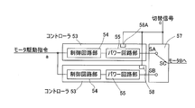
図9に示す第9実施形態では、コントローラ53を一つとし、このコントローラ53におけるパワー回路部55を、選択的に使用可能に2個設けている。また、切替信号cによって動作する切替手段として、中間側の切替手段60と出力側の切替手段57と内部側の切替手段58Aが設けられている。中間側の切替手段60は、切替信号cに応答して、制御回路部54の出力端子を、2つのパワー回路部55の入力端子に対して切り替えるスイッチング回路からなる。出力側の切替手段57は、切替信号cに応答し、複数のパワー回路部55の出力端子とモータBの入力端子との接続を切り換えるスイッチング回路等からなる。この実施形態の内部側の切替手段58Aは、切替信号cに応答して、バッテリと接続されるパワー回路部55を切り替える。
この構成の場合、切替信号cに応答して、中間側の切替手段60が切り替わることで、パワー回路部55に接続される制御回路部54が切り替わる。また、切替信号cに応答して出力側の切替手段57は、モータBに接続するパワー回路部55を切り替える。内部側の切替手段58Aは、切替信号cに応答して、バッテリと接続するパワー回路部55を切り替える。これにより、使用中のパワー回路部55に故障等の異常が生じたときに、別のパワー回路部55を使用して正常なモータ駆動を続けることができる。
図10に示す第10実施形態は、図9に示す第9実施形態に対して、中間側の切替手段60を省略し、2つの制御回路部54の出力端が常パワー回路部55に接続された状態としてある。その他の構成は図9の実施形態と同様である。この構成の場合も、切替信号cに応答して、出力側の切替手段57により、モータBと接続されるパワー回路部55が切り替わる。これにより、使用中のパワー回路部55に故障等の異常が生じたときに、別のパワー回路部55を使用して正常なモータ駆動を続けることができる。
図11に示す第11の実施形態は、図9に示す第9実施形態に対して、出力側の切替手段57を省略し、2つのパワー回路部55の出力端が常にモータBに接続された状態としてある。その他の構成は図9に示す第9実施形態と同様である。この構成の場合も、切替信号cに応答して、中間の切替手段60により、制御回路部54が接続されるパワー回路部55が切替えられる。そのため、その切り替えられたパワー回路部55でモータBが駆動されることになる。これにより、使用中のパワー回路部55に故障等の異常が生じたときに、別のパワー回路部55を使用して正常なモータ駆動を続けることができる。
図12に示す第12実施形態は、図1に示す第1実施形態において、切替手段として内部側の切替手段58のみを設けたものである。その他の構成は、図1に示す第1実施形態と同様である。この構成の場合、切替信号cに応答して、電源が投入される制御回路部54、およびバッテリと接続状態となるパワー回路部55が切り替わる。そのため、使用中のコントローラ53に故障等の異常が生じたときに、別のコントローラ53を使用して正常なモータ駆動を続けることができる。
次に、図13~図15と共に、インホイールモータ駆動装置の具体例を説明する。図13は、車両の車輪用軸受AとモータBとの間に減速機Cを介在させ、車輪用軸受Aで支持されるハブとモータBの出力軸24とを同軸心上で連結したインホイールモータ駆動装置を示す。これら車輪用軸受A、モータB、および減速機Cは、互いに一つの組立部品としてユニット化されたインホイールモータアセンブリUを構成する。車輪用軸受Aは、減速機Cのハウジング33bまたはモータBのハウジング22の外周部で、ナックル等の懸架装置(図示せず)を介して車体に固定される。上記モータBが、前記電気自動車用コントローラ装置51によって駆動される。
減速機Cは、5倍以上の減速比を有するものであり、8倍以上の減速比を持つものとすることが好ましい。この例では、減速機Cは、サイクロイド減速機であって、モータBの出力軸24に同軸に連結される入力軸32に偏心部32a,32bを形成し、偏心部32a,32bにそれぞれ軸受35を介して曲線板34a,34bを装着し、曲線板34a,34bの偏心運動を車輪軸受Aへ回転運動として伝達する構成である。
すなわち、減速機Cにつき、モータBの回転を曲線板34a,34bの偏心運動とし、この偏心運動を回転運動としてハブに伝達するサイクロイド減速機とすることにより、コンパクトで大きな減速比が得られる減速機Cとこの減速機Cのコンパクトな配置構造を有くコンパクトに設計でき、1段で1/10以上の大きな減速比を得ることができる。
このインホイールモータアセンブリUの機械部分の具体的構成例を説明する。なお、この明細書において、車両に取付けた状態で車両の車幅方向の外側寄りとなる側をアウトボード側と呼び、車両の中央寄りとなる側をインボード側と呼ぶ。車輪用軸受Aは、軸受の転走面を形成した内方部材2がハブを構成する第3世代型の内輪回転タイプのハブベアリングとされている。
この車輪用軸受Aは、内周に複列の転走面3を形成した外方部材1と、これら各転走面3に対向する転走面4を形成した内方部材2と、これら外方部材1および内方部材2の転走面3,4間に介在した複列の転動体5とで構成される。内方部材2は、車両の車輪を取付けるハブを兼用する。この車輪用軸受Aは、複列のアンギュラ玉軸受型とされていて、転動体5はボールからなり、各列毎に保持器6で保持されている。上記転走面3,4は断面円弧状であり、各転走面3,4は接触角が外向きとなるように形成されている。外方部材1とハブ2との間の軸受空間のアウトボード側端は、シール部材7でシールされている。
外方部材1は静止側軌道輪となるものであって、減速機Cのハウジング33のうちのアウトボード側のハウジング33bに取付けるフランジ1aを外周に有し、全体が一体の部品とされている。フランジ1aには、周方向の複数箇所にボルト挿通孔14が設けられている。また、ハウジング33bには、ボルト挿通孔14に対応する位置に、内周にねじが切られたボルト螺着孔44が設けられている。ボルト挿通孔14に挿通した取付ボルト15をボルト螺着孔44に螺着させることにより、外方部材1がハウジング33bに取付けられる。
内方部材2は、車輪(図示せず)の取付用のハブフランジ9aを有するアウトボード側材9と、このアウトボード側材9の内周にアウトボード側が嵌合して加締めによってアウトボード側材9に一体化されたインボード側材10とでなる。これらアウトボード側材9およびインボード側材10に、前記各列の転走面4が形成されている。インボード側材10の中心には貫通孔11が設けられている。ハブフランジ9aには、周方向複数箇所にハブボルト16の挿入孔17が設けられている。アウトボード側材9のハブフランジ9aの根元部付近には、ホイールWおよび制動部品19を案内する円筒状のパイロット部13がアウトボード側に突出している。このパイロット部13の内周には、前記貫通孔11のアウトボード側端を塞ぐキャップ18が取付けられている。
モータBは、筒状のハウジング22に固定したステータ23と出力軸24に取付けたロータ25との間にラジアルギャップを設けたラジアルギャップ型のものである。出力軸24は、減速機Cのインボード側のハウジング33aの筒部に2つの軸受26で片持ち支持されている。出力軸24とハウジング33a間の隙間のインボード側端は、シール部材20でシールされている。ハウジング22の周壁部には冷却媒体流路45が全周に渡り設けられている。冷却媒体流路45には、ポンプ等の供給駆動源(図示せず)により、油または水溶性の冷却剤等からなる冷却媒体が、循環させられる。
減速機Cは、上記のようにサイクロイド減速機であり、図14のように外形がなだらかな波状のトロコイド曲線で形成された2枚の曲線板34a,34bが、それぞれ軸受35を介して入力軸32の各偏心部32a,32bに装着してある。これら各曲線板34a,34bの偏心運動を外周側で案内する複数の外ピン36を、それぞれハウジング33bに差し渡して設け、内方部材2のインボード側材10に取付けた複数の内ピン38を、各曲線板34a,34bの内部に設けられた複数の円形の貫通孔39に挿入状態に係合させてある。入力軸32は、モータBの出力軸24とスプライン結合されて一体に回転する。なお、入力軸32はインボード側のハウジング33aと内方部材2のインボード側材10の内径面とに2つの軸受40で両持ち支持されている。減速機Cは、ホイールW内に位置する、つまり、ホイールWの幅Eの範囲内に位置し、ホイールWからホイール軸心Oの方向にはみ出ていない。
モータBの出力軸24が回転すると、これと一体回転する入力軸32に取付けられた各曲線板34a,34bが偏心運動を行う。この各曲線板34a,34bの偏心運動が、内ピン38と貫通孔39との係合によって、内方部材2に回転運動として伝達される。出力軸24の回転に対して内方部材2の回転は減速されたものとなる。
前記2枚の曲線板34a,34bは、互いに偏心運動による振動が打ち消されるように180°位相をずらして入力軸32の各偏心部32a,32bに装着され、各偏心部32a,32bの両側には、各曲線板34a,34bの偏心運動によって発生する回転軸に直交する軸回りの慣性偶力よる振動を打ち消すように、各偏心部32a,32bの偏心方向と逆方向へ偏心させたカウンターウエイト41が装着されている。
図15に拡大して示すように、前記各外ピン36と内ピン38には軸受42,43が装着され、これらの軸受42,43の外輪42a,43aが、それぞれ各曲線板34a,34bの外周と各貫通孔39の内周とに転接する。したがって、外ピン36と各曲線板34a,34bの外周との接触抵抗、および内ピン38と各貫通孔39の内周との接触抵抗を低減し、各曲線板34a,34bの偏心運動をスムーズに内方部材2に回転運動として伝達することができる。
以上のとおり、図面を参照しながら好適な実施形態を説明したが、当業者であれば、本件明細書を見て、自明な範囲内で種々の変更および修正を容易に想定するであろう。したがって、そのような変更および修正は、請求の範囲から定まる発明の範囲内のものと解釈される。
51…電気自動車用コントローラ装置
52…電気制御ユニット
53…コントローラ
54…制御回路部
55…パワー回路部
56…異常判定手段
57…出力側の切替手段
58…内部側の切替手段
58A…内部側の切替手段
59…入力側の切替手段
60…中間側の切替手段
A…車輪用軸受
B…モータ
C…減速機
U…インホイールモータ駆動装置(アセンブリ)
52…電気制御ユニット
53…コントローラ
54…制御回路部
55…パワー回路部
56…異常判定手段
57…出力側の切替手段
58…内部側の切替手段
58A…内部側の切替手段
59…入力側の切替手段
60…中間側の切替手段
A…車輪用軸受
B…モータ
C…減速機
U…インホイールモータ駆動装置(アセンブリ)
Claims (15)
- 電気自動車を駆動するモータのコントローラ装置であって、モータの駆動電流を出力するパワー回路部、および上位の制御手段から与えられるモータ駆動指令に応答して前記パワー回路部の制御を行う弱電回路の制御回路部を有するコントローラを複数備え、定められた規則により使用中のコントローラの異常を判定して切替信号を生成する異常判定手段と、この異常判定手段の出力する切替信号に応答して、前記モータに対して機能する状態にあるコントローラを切り替える切替手段を設けた電気自動車用コントローラ装置。
- 請求項1において、前記複数のコントローラの前記制御回路部は、常に電源を投入しかつ前記モータ駆動指令を入力してスタンバイ状態にしておき、前記異常判定手段が、使用中のコントローラが異常であると判定して前記切替信号を出力したときに、前記切替手段が別のコントローラをモータに対して機能する状態とする電気自動車用コントローラ装置。
- 請求項1において、前記モータは、8以上の減速比を有する減速機を介して自動車のホイールにトルク伝達するものである電気自動車用コントローラ装置。
- 請求項3において、前記減速機はサイクロイド減速機である電気自動車用コントローラ装置。
- 請求項3において、前記減速機とモータと車輪用軸受とが互いに結合されたアセンブリであるインホイールモータ装置を構成し、前記減速機の一部がホイール内に位置する電気自動車用コントローラ装置。
- 電気自動車を駆動するモータのコントローラ装置であって、モータの駆動電流を出力するパワー回路部、および上位の制御手段から与えられるモータ駆動指令に応答して前記パワー回路の制御を行う弱電回路の制御回路部を有するコントローラを備え、前記コントローラは、前記制御回路部として、同じパワー回路部に対して選択的に使用される複数の制御回路部を有し、定められた規則により使用中の制御回路部の異常を判定して切替信号を生成する異常判定手段と、この異常判定手段の出力する切替信号に応答して、前記パワー回路部に対して機能する状態にある別の制御回路部に切り替える切替手段を設けた電気自動車用コントローラ装置。
- 請求項6において、複数個の制御回路部のうち、異常時に使用される前記別の制御回路部は、電磁ノイズに耐性を有するアナログ回路を主とする回路構成とした電気自動車用コントローラ装置。
- 請求項6において、前記複数の制御回路部には常に電源を投入してスタンバイ状態にしておき、前記異常判定手段が、使用中の制御回路部が異常であると判定して切替信号を出力したときに、前記切替手段が前記別の制御回路部をモータに対して機能する状態とする電気自動車用コントローラ装置。
- 請求項6において、前記モータは、8以上の減速比を有する減速機を介して自動車のホイールにトルク伝達するものである電気自動車用コントローラ装置。
- 請求項6において、前記減速機はサイクロイド減速機である電気自動車用コントローラ装置。
- 請求項6において、前記減速機とモータと車輪用軸受とが互いに結合されたアセンブリであるインホイールモータ装置を構成し、前記減速機の一部がホイール内に位置する電気自動車用コントローラ装置。
- 電気自動車を駆動するモータのコントローラ装置であって、モータの駆動電流を出力するパワー回路部、および上位の制御手段から与えられるモータ駆動指令に応答して前記パワー回路の制御を行う弱電回路の制御回路部を有するコントローラを備え、前記コントローラは、前記パワー回路部として、同じ制御回路部により制御されて選択的に使用される複数のパワー回路部を有し、定められた規則により使用中のパワー回路部の異常を判定して切替信号を生成する異常判定手段と、この異常判定手段の出力する切替信号に応答して、前記モータに対し機能する状態にあるパワー回路部を切り替える切替手段を設けた電気自動車用コントローラ装置。
- 請求項12において、前記モータは、8以上の減速比を有する減速機を介して自動車のホイールにトルク伝達するものである電気自動車用コントローラ装置。
- 請求項12において、前記減速機はサイクロイド減速機である電気自動車用コントローラ装置。
- 請求項12において、前記減速機とモータと車輪用軸受とが互いに結合されたアセンブリであるインホイールモータ装置を構成し、前記減速機がホイール内に位置する電気自動車用コントローラ装置。
Priority Applications (3)
| Application Number | Priority Date | Filing Date | Title |
|---|---|---|---|
| CN201180015725.2A CN102822002B (zh) | 2010-03-26 | 2011-03-16 | 电动汽车用控制装置 |
| EP11759272.5A EP2554426A4 (en) | 2010-03-26 | 2011-03-16 | CONTROL DEVICE FOR ONE ELECTRIC VEHICLE |
| US13/613,670 US8558499B2 (en) | 2010-03-26 | 2012-09-13 | Controller apparatus for electric vehicle |
Applications Claiming Priority (2)
| Application Number | Priority Date | Filing Date | Title |
|---|---|---|---|
| JP2010-072057 | 2010-03-26 | ||
| JP2010072057A JP5528168B2 (ja) | 2010-03-26 | 2010-03-26 | 電気自動車用コントローラ装置 |
Related Child Applications (1)
| Application Number | Title | Priority Date | Filing Date |
|---|---|---|---|
| US13/613,670 Continuation US8558499B2 (en) | 2010-03-26 | 2012-09-13 | Controller apparatus for electric vehicle |
Publications (1)
| Publication Number | Publication Date |
|---|---|
| WO2011118466A1 true WO2011118466A1 (ja) | 2011-09-29 |
Family
ID=44673023
Family Applications (1)
| Application Number | Title | Priority Date | Filing Date |
|---|---|---|---|
| PCT/JP2011/056183 Ceased WO2011118466A1 (ja) | 2010-03-26 | 2011-03-16 | 電気自動車用コントローラ装置 |
Country Status (5)
| Country | Link |
|---|---|
| US (1) | US8558499B2 (ja) |
| EP (1) | EP2554426A4 (ja) |
| JP (1) | JP5528168B2 (ja) |
| CN (1) | CN102822002B (ja) |
| WO (1) | WO2011118466A1 (ja) |
Cited By (1)
| Publication number | Priority date | Publication date | Assignee | Title |
|---|---|---|---|---|
| CN104066645A (zh) * | 2011-11-25 | 2014-09-24 | 本田技研工业株式会社 | 电动式鞍乘型车辆 |
Families Citing this family (40)
| Publication number | Priority date | Publication date | Assignee | Title |
|---|---|---|---|---|
| US8615295B2 (en) | 2009-03-17 | 2013-12-24 | Cardiothrive, Inc. | External defibrillator |
| JP2013255358A (ja) * | 2012-06-07 | 2013-12-19 | Jtekt Corp | 車両用走行装置 |
| JP5790598B2 (ja) * | 2012-07-05 | 2015-10-07 | 株式会社デンソー | 組電池の制御装置 |
| KR101494886B1 (ko) | 2012-10-22 | 2015-02-24 | 자동차부품연구원 | 전기자동차용 파워트레인 |
| US10279189B2 (en) | 2013-06-14 | 2019-05-07 | Cardiothrive, Inc. | Wearable multiphasic cardioverter defibrillator system and method |
| US9616243B2 (en) | 2013-06-14 | 2017-04-11 | Cardiothrive, Inc. | Dynamically adjustable multiphasic defibrillator pulse system and method |
| US9907970B2 (en) | 2013-06-14 | 2018-03-06 | Cardiothrive, Inc. | Therapeutic system and method using biphasic or multiphasic pulse waveform |
| US10149973B2 (en) | 2013-06-14 | 2018-12-11 | Cardiothrive, Inc. | Multipart non-uniform patient contact interface and method of use |
| US9656094B2 (en) | 2013-06-14 | 2017-05-23 | Cardiothrive, Inc. | Biphasic or multiphasic pulse generator and method |
| US9833630B2 (en) | 2013-06-14 | 2017-12-05 | Cardiothrive, Inc. | Biphasic or multiphasic pulse waveform and method |
| KR101619227B1 (ko) * | 2014-10-20 | 2016-05-10 | 현대자동차주식회사 | 차량용 미들 도어 또는 스텝의 고장 진단 방법 |
| DE102016211498A1 (de) * | 2016-06-27 | 2017-12-28 | Robert Bosch Gmbh | Verfahren und Vorrichtung zur externen Überwachung einer Leistungselektronik |
| JP6755763B2 (ja) * | 2016-09-23 | 2020-09-16 | Ntn株式会社 | 2軸型インバータ装置 |
| WO2018173561A1 (ja) * | 2017-03-23 | 2018-09-27 | 日立オートモティブシステムズ株式会社 | 車両制御装置 |
| US20180281597A1 (en) * | 2017-03-28 | 2018-10-04 | NextEv USA, Inc. | Electric vehicle safety concept using distributed vehicle control units |
| CN108803399B (zh) * | 2017-05-02 | 2024-03-19 | 联合汽车电子有限公司 | 车辆控制器及其控制方法 |
| CN108859861A (zh) * | 2017-05-11 | 2018-11-23 | 杭州长江汽车有限公司 | 一种电动车辆的控制系统、控制方法及电动车辆 |
| JP6884206B2 (ja) * | 2017-06-28 | 2021-06-09 | 日立Astemo株式会社 | 車両用ブレーキシステム |
| JP6822355B2 (ja) * | 2017-09-06 | 2021-01-27 | トヨタ自動車株式会社 | 制動力制御システム |
| CN109910613B (zh) * | 2017-12-13 | 2021-09-07 | 宝沃汽车(中国)有限公司 | 扭矩关断方法、扭矩关断系统和车辆 |
| US10828500B2 (en) | 2017-12-22 | 2020-11-10 | Cardiothrive, Inc. | External defibrillator |
| US10836402B2 (en) * | 2017-12-27 | 2020-11-17 | Micron Technology, Inc. | Determination of reliability of vehicle control commands via redundancy |
| CN109991954B (zh) * | 2017-12-29 | 2021-05-25 | 中兴通讯股份有限公司 | 电机控制器的容错控制方法、系统及设备、存储介质 |
| DE102018114490A1 (de) * | 2018-06-18 | 2019-12-19 | Schaeffler Technologies AG & Co. KG | Verfahren zur Steuerung eines elektrischen Antriebs eines Kraftfahrzeuges; sowie Computerprogrammprodukt |
| KR102517947B1 (ko) * | 2018-06-20 | 2023-04-04 | 에이치엘만도 주식회사 | 차량용 모터 제어 장치 및 방법 |
| CN108859867B (zh) * | 2018-08-13 | 2020-12-01 | 奇瑞汽车股份有限公司 | 电动汽车驱动方法及系统 |
| FR3085562B1 (fr) * | 2018-08-30 | 2020-09-04 | Safran Nacelles | Aiguilleur electrique haute disponibilite : controle d’une chaine d’actionnement simplex par un controle redonde |
| CN109747422A (zh) * | 2018-12-28 | 2019-05-14 | 南京越博电驱动系统有限公司 | 一种提升纯电动客车can网络通信可靠性的方法 |
| CN111376852A (zh) * | 2018-12-29 | 2020-07-07 | 联合汽车电子有限公司 | 车辆安全控制系统 |
| US10790739B1 (en) | 2019-05-29 | 2020-09-29 | Hamilton Sundstrand Corporation | Redundant power supply having diverse dual controllers |
| CN114007912B (zh) * | 2019-06-07 | 2024-04-09 | 汉拿万都株式会社 | 制动系统的控制装置结构 |
| CN110311618A (zh) * | 2019-08-01 | 2019-10-08 | 四川九洲电器集团有限责任公司 | 电机控制系统 |
| CN110649760B (zh) * | 2019-11-06 | 2024-10-01 | 西安合升动力科技有限公司 | 一体式双闭环控制的节能减速电机及其控制方法 |
| CN113581097B (zh) * | 2020-04-30 | 2024-09-10 | 比亚迪股份有限公司 | 控制车辆配电的方法和配电装置、存储介质和车辆 |
| DE102020211902A1 (de) * | 2020-09-23 | 2022-03-24 | Robert Bosch Gesellschaft mit beschränkter Haftung | Vorrichtung für ein automatisches Parkbremssystem |
| US11837984B2 (en) | 2021-05-14 | 2023-12-05 | Delphi Technologies Ip Limited | Dual supply dual control architecture |
| CN113293565B (zh) * | 2021-05-20 | 2023-08-18 | 海信冰箱有限公司 | 洗衣机及其控制方法、控制电路 |
| CN113556061A (zh) * | 2021-07-20 | 2021-10-26 | 中国第一汽车股份有限公司 | 轮毂电机控制系统、控制方法、轮胎以及驾驶设备 |
| WO2023004625A1 (zh) * | 2021-07-28 | 2023-02-02 | 华为技术有限公司 | 一种电动汽车控制系统和电动汽车 |
| CN118288795B (zh) * | 2024-05-10 | 2026-01-02 | 奇瑞汽车股份有限公司 | 一种轮毂电机控制器故障控制方法及系统 |
Citations (9)
| Publication number | Priority date | Publication date | Assignee | Title |
|---|---|---|---|---|
| JPH0284003A (ja) * | 1988-09-16 | 1990-03-26 | Hitachi Ltd | 電気自動車の動力システム |
| JP2001310743A (ja) * | 2000-04-26 | 2001-11-06 | Toyoda Mach Works Ltd | 車両用操舵制御装置 |
| JP2005287129A (ja) * | 2004-03-29 | 2005-10-13 | Toshiba Corp | 待機系電源装置 |
| JP2006335181A (ja) * | 2005-06-01 | 2006-12-14 | Nissan Motor Co Ltd | Hev車両の制御システム |
| JP2007306713A (ja) * | 2006-05-11 | 2007-11-22 | Toshiba Corp | 電気車用電源装置 |
| JP2008168790A (ja) | 2007-01-12 | 2008-07-24 | Ntn Corp | インホイールモータ駆動装置 |
| JP2008172975A (ja) | 2007-01-15 | 2008-07-24 | Ntn Corp | インホイールモータ駆動装置 |
| JP2008245497A (ja) * | 2007-03-29 | 2008-10-09 | Toshiba Corp | 車両用電源装置 |
| JP2009074583A (ja) * | 2007-09-19 | 2009-04-09 | Ntn Corp | サイクロイド減速機、およびインホイールモータ駆動装置 |
Family Cites Families (10)
| Publication number | Priority date | Publication date | Assignee | Title |
|---|---|---|---|---|
| JP2752539B2 (ja) * | 1991-09-21 | 1998-05-18 | 株式会社日立製作所 | 車両用電動機の制御装置 |
| JP3257971B2 (ja) * | 1997-09-12 | 2002-02-18 | 本田技研工業株式会社 | 電動パワーステアリング装置 |
| JP3696384B2 (ja) * | 1997-09-16 | 2005-09-14 | 本田技研工業株式会社 | 電動機の駆動装置 |
| DE19901272A1 (de) * | 1999-01-15 | 2000-07-27 | Alstom Anlagen Und Antriebssys | Verfahren zum Betreiben eines elektrischen Umrichters |
| JP4799199B2 (ja) * | 2005-02-16 | 2011-10-26 | Ntn株式会社 | インホイールモータ駆動装置 |
| US7277304B2 (en) * | 2005-09-23 | 2007-10-02 | Gm Global Technology Operations, Inc. | Multiple inverter system with single controller and related operating method |
| JP4774975B2 (ja) * | 2005-12-15 | 2011-09-21 | トヨタ自動車株式会社 | 電動機の制御装置 |
| JP4491434B2 (ja) * | 2006-05-29 | 2010-06-30 | トヨタ自動車株式会社 | 電力制御装置およびそれを備えた車両 |
| JP5052084B2 (ja) * | 2006-09-19 | 2012-10-17 | Ntn株式会社 | インホイール型モータ内蔵センサ付きアクスルユニット |
| US20090296433A1 (en) * | 2008-05-29 | 2009-12-03 | General Electric Company | Circuit and topology for very high reliability power electronics system |
-
2010
- 2010-03-26 JP JP2010072057A patent/JP5528168B2/ja active Active
-
2011
- 2011-03-16 WO PCT/JP2011/056183 patent/WO2011118466A1/ja not_active Ceased
- 2011-03-16 EP EP11759272.5A patent/EP2554426A4/en not_active Ceased
- 2011-03-16 CN CN201180015725.2A patent/CN102822002B/zh active Active
-
2012
- 2012-09-13 US US13/613,670 patent/US8558499B2/en active Active
Patent Citations (9)
| Publication number | Priority date | Publication date | Assignee | Title |
|---|---|---|---|---|
| JPH0284003A (ja) * | 1988-09-16 | 1990-03-26 | Hitachi Ltd | 電気自動車の動力システム |
| JP2001310743A (ja) * | 2000-04-26 | 2001-11-06 | Toyoda Mach Works Ltd | 車両用操舵制御装置 |
| JP2005287129A (ja) * | 2004-03-29 | 2005-10-13 | Toshiba Corp | 待機系電源装置 |
| JP2006335181A (ja) * | 2005-06-01 | 2006-12-14 | Nissan Motor Co Ltd | Hev車両の制御システム |
| JP2007306713A (ja) * | 2006-05-11 | 2007-11-22 | Toshiba Corp | 電気車用電源装置 |
| JP2008168790A (ja) | 2007-01-12 | 2008-07-24 | Ntn Corp | インホイールモータ駆動装置 |
| JP2008172975A (ja) | 2007-01-15 | 2008-07-24 | Ntn Corp | インホイールモータ駆動装置 |
| JP2008245497A (ja) * | 2007-03-29 | 2008-10-09 | Toshiba Corp | 車両用電源装置 |
| JP2009074583A (ja) * | 2007-09-19 | 2009-04-09 | Ntn Corp | サイクロイド減速機、およびインホイールモータ駆動装置 |
Non-Patent Citations (1)
| Title |
|---|
| See also references of EP2554426A4 * |
Cited By (1)
| Publication number | Priority date | Publication date | Assignee | Title |
|---|---|---|---|---|
| CN104066645A (zh) * | 2011-11-25 | 2014-09-24 | 本田技研工业株式会社 | 电动式鞍乘型车辆 |
Also Published As
| Publication number | Publication date |
|---|---|
| CN102822002A (zh) | 2012-12-12 |
| JP5528168B2 (ja) | 2014-06-25 |
| US8558499B2 (en) | 2013-10-15 |
| CN102822002B (zh) | 2015-01-07 |
| JP2011205823A (ja) | 2011-10-13 |
| US20130002179A1 (en) | 2013-01-03 |
| EP2554426A4 (en) | 2016-10-12 |
| EP2554426A1 (en) | 2013-02-06 |
Similar Documents
| Publication | Publication Date | Title |
|---|---|---|
| JP5528168B2 (ja) | 電気自動車用コントローラ装置 | |
| JP5481236B2 (ja) | 電気自動車のモータ駆動システム | |
| JP5705585B2 (ja) | 電気自動車 | |
| EP2784930B1 (en) | Motor control device | |
| CN103384614B (zh) | 电动汽车 | |
| CN103442930B (zh) | 电动汽车 | |
| JP5893361B2 (ja) | モータの制御装置 | |
| WO2012121200A1 (ja) | モータの診断方法 | |
| WO2012114902A1 (ja) | 電気自動車 | |
| JP5936306B2 (ja) | 電気自動車 | |
| WO2014069280A1 (ja) | インホイールモータ駆動装置 | |
| US20190085957A1 (en) | Electrically driven actuator | |
| WO2013073547A1 (ja) | 電気自動車のモータ制御装置 | |
| WO2014097927A1 (ja) | インホイールモータ駆動装置 | |
| JP2014241720A (ja) | 電気自動車用駆動モータの診断装置 | |
| JP6199454B2 (ja) | モータの制御装置 | |
| WO2012114900A1 (ja) | 電気自動車 | |
| JP5781326B2 (ja) | 電気自動車 | |
| JP2008172975A (ja) | インホイールモータ駆動装置 | |
| JP2012176650A (ja) | インホイールモータ駆動装置およびモータの制御方法 |
Legal Events
| Date | Code | Title | Description |
|---|---|---|---|
| WWE | Wipo information: entry into national phase |
Ref document number: 201180015725.2 Country of ref document: CN |
|
| 121 | Ep: the epo has been informed by wipo that ep was designated in this application |
Ref document number: 11759272 Country of ref document: EP Kind code of ref document: A1 |
|
| WWE | Wipo information: entry into national phase |
Ref document number: 8231/DELNP/2012 Country of ref document: IN |
|
| NENP | Non-entry into the national phase |
Ref country code: DE |
|
| WWE | Wipo information: entry into national phase |
Ref document number: 2011759272 Country of ref document: EP |