WO2011121684A1 - Cassette de ruban encreur et imprimante couleur l'utilisant - Google Patents
Cassette de ruban encreur et imprimante couleur l'utilisant Download PDFInfo
- Publication number
- WO2011121684A1 WO2011121684A1 PCT/JP2010/006214 JP2010006214W WO2011121684A1 WO 2011121684 A1 WO2011121684 A1 WO 2011121684A1 JP 2010006214 W JP2010006214 W JP 2010006214W WO 2011121684 A1 WO2011121684 A1 WO 2011121684A1
- Authority
- WO
- WIPO (PCT)
- Prior art keywords
- ink ribbon
- cassette
- shaft
- ink
- stopper
- Prior art date
- Legal status (The legal status is an assumption and is not a legal conclusion. Google has not performed a legal analysis and makes no representation as to the accuracy of the status listed.)
- Ceased
Links
Images



Classifications
-
- B—PERFORMING OPERATIONS; TRANSPORTING
- B41—PRINTING; LINING MACHINES; TYPEWRITERS; STAMPS
- B41J—TYPEWRITERS; SELECTIVE PRINTING MECHANISMS, i.e. MECHANISMS PRINTING OTHERWISE THAN FROM A FORME; CORRECTION OF TYPOGRAPHICAL ERRORS
- B41J2/00—Typewriters or selective printing mechanisms characterised by the printing or marking process for which they are designed
- B41J2/315—Typewriters or selective printing mechanisms characterised by the printing or marking process for which they are designed characterised by selective application of heat to a heat sensitive printing or impression-transfer material
- B41J2/32—Typewriters or selective printing mechanisms characterised by the printing or marking process for which they are designed characterised by selective application of heat to a heat sensitive printing or impression-transfer material using thermal heads
- B41J2/325—Typewriters or selective printing mechanisms characterised by the printing or marking process for which they are designed characterised by selective application of heat to a heat sensitive printing or impression-transfer material using thermal heads by selective transfer of ink from ink carrier, e.g. from ink ribbon or sheet
-
- B—PERFORMING OPERATIONS; TRANSPORTING
- B41—PRINTING; LINING MACHINES; TYPEWRITERS; STAMPS
- B41J—TYPEWRITERS; SELECTIVE PRINTING MECHANISMS, i.e. MECHANISMS PRINTING OTHERWISE THAN FROM A FORME; CORRECTION OF TYPOGRAPHICAL ERRORS
- B41J17/00—Mechanisms for manipulating page-width impression-transfer material, e.g. carbon paper
- B41J17/32—Detachable carriers or holders for impression-transfer material mechanism
Definitions
- the present invention relates to an ink ribbon cassette in which ink ribbons of various colors used for printing are loaded, and a color printer that performs printing in a plurality of colors using such an ink ribbon cassette.
- the ink of the ink ribbon is used using a thermal head.
- a thermal head such as a label temporarily attached to a mount or a belt-like sheet for tag production
- the ink of the ink ribbon is used using a thermal head.
- Thermal transfer printers that perform printing by transferring to paper are used. In the thermal transfer printer, printing is performed by transferring the ink ribbon ink onto the paper by the heat generated by the heating element of the thermal head while conveying the paper and the ink ribbon at the same speed in the same direction.
- ink ribbons of a plurality of colors are required, and therefore, an ink ribbon cassette loaded with ink ribbons of each color is generally used.
- an ink ribbon cassette loaded with ink ribbons of each color is generally used.
- a plurality of types of ink ribbon cassettes are mounted on a color printer, if the positions where the ink ribbon cassettes are mounted are wrong, printing is performed with an incorrect color.
- Patent Document 1 discloses an ink ink ribbon cassette that stably prevents looseness of an ink ribbon.
- This ink ribbon cassette has a case in which the ribbon storage part, ribbon delivery path, and ribbon reception path are integrated, and a part of the ink ribbon cassette exits the ribbon storage part from the ribbon delivery path and circulates again into the ribbon storage part through the ribbon reception path. And an endless ink ribbon, and a ribbon running mechanism provided in the ribbon storage section.
- the drive gear abuts on one surface of the ink ribbon that passes, the pull-in driven gear abuts on the other side rearward in the travel direction, the push-in driven gear abuts on the other side, and the drive gear sandwiches the ink ribbon in between.
- An arc guide that is provided in mesh with each driven gear, and whose rotation shaft of the push-down driven gear is formed in an arc shape with the rotation shaft of the drive gear as the center point to the point where the pull-in driven gear and the push-down driven gear mesh with each other Is slidably engaged.
- the present invention prevents the ink ribbon from loosening when the ink ribbon cassette is not attached to the color printer, and attaches the ink ribbon cassette to the color printer.
- the purpose is to prevent erroneous printing even if the position is wrong.
- an ink ribbon cassette is an ink ribbon cassette loaded with an ink ribbon used for printing in a color printer, and a plurality of openings are formed at a plurality of different positions.
- a cassette case an ink ribbon supply shaft rotatably supported by the cassette case for supplying an unused ink ribbon, and provided with a gear-shaped first stopper along the rotation direction;
- An ink ribbon take-up shaft that is rotatably supported by the cassette case for winding the ink ribbon and provided with a gear-like second stopper along the direction of rotation is engaged with the first and second stoppers.
- the engaging portion engages with the first and second stoppers to lock the ink ribbon supply shaft and the ink ribbon take-up shaft, and a plurality of openings formed in the cassette case. Since the ink ribbon supply shaft and the ink ribbon take-up shaft are unlocked when at least one pin is inserted into at least one predetermined opening corresponding to the type of the ink ribbon from among the ink ribbon cassette, the ink ribbon cassette In addition to preventing slack of the ink ribbon when not mounted on the color printer, it is possible to prevent erroneous printing even if the ink ribbon cassette is mounted on the color printer in the wrong position.
- FIG. 3 is a perspective view illustrating a state in which the ink ribbon cassette according to each embodiment of the invention is attached to the printer. It is a figure which shows the ink ribbon cassette which concerns on the 1st Embodiment of this invention. It is a figure which shows the ink ribbon cassette which concerns on the 2nd Embodiment of this invention. It is a figure which shows the ink ribbon cassette which concerns on the 3rd Embodiment of this invention.
- FIG. 1 is a schematic sectional view showing a color printer equipped with an ink ribbon cassette according to each embodiment of the present invention.
- This color printer is a printer for printing on a printing medium (paper) such as a label temporarily attached to a mount or a belt-like sheet for manufacturing a tag, and uses an ink ribbon ink by using a thermal head. Is printed on the paper.
- a printing medium paper
- a thermal head a thermal head
- a sheet 1 is rotatably supported on a sheet supply shaft 11 provided in a housing of a printer 10 as a roll sheet 2 wound in a roll shape.
- the paper 1 pulled out from the paper supply shaft 11 is supplied between a driving roller 12 that rotates by being driven by a motor provided in the housing, and a driven roller 13 that rotates as the driving roller 12 rotates. It is nipped and conveyed by the driving roller 12 and the driven roller 13.
- ink ribbon cassettes 20a to 20d are mounted on the frame 14 of the housing from the upstream side in the transport direction (right side in the figure) to the downstream side in the transport direction (left side in the figure).
- the ink ribbon cassette 20a is loaded with a yellow (yellow) ink ribbon
- the ink ribbon cassette 20b is loaded with a magenta ink ribbon
- the ink ribbon cassette 20c is loaded with a cyan ink ribbon.
- the ink ribbon cassette 20d is loaded with a black (black) ink ribbon. *
- the ink ribbon 23 is stretched between the ink ribbon supply shaft 21 and the ink ribbon take-up shaft 22.
- the ink ribbon winding shaft 22 is driven to rotate by a motor provided in the housing.
- the printer 10 has four platen rollers 15a to 15d and four thermal heads 16a to 16d corresponding to the four types of ink ribbon cassettes 20a to 20d.
- the thermal heads 16a to 16d are inserted into the ink ribbon cassettes 20a to 20d, respectively, and are arranged to face the platen rollers 15a to 15d, respectively.
- the unused ink ribbon 23 supported while being wound in a roll on the ink ribbon supply shaft 21 of the ink ribbon cassette 20a is supplied together with the paper 1 between the platen roller 15a and the thermal head 16a.
- the ink ribbon 23 is taken up by the ink ribbon take-up shaft 22.
- the platen roller 15a is driven and rotated by a motor provided in the housing, thereby conveying the paper 1 and the ink ribbon 23 in the same direction at the same speed.
- the thermal head 16a has a plurality of fine heating elements in the width direction that generate heat when an electric current flows. Printing is performed using a yellow ink ribbon loaded in the ink ribbon cassette 20a by applying a voltage to these heat generating elements to cause the heat generating elements to generate heat and transferring the ink on the ink ribbon 23 to the paper 1. Is done. *
- the platen rollers 15b to 15d are configured similarly to the platen roller 15a, and the thermal heads 16b to 16d are configured similarly to the thermal head 16a.
- the sheet 1 that has passed the position of the platen roller 15a sequentially passes the positions of the platen rollers 15b to 15d, and the magenta, cyan, and black ink ribbons loaded in the ink ribbon cassettes 20b to 20d, respectively, by the thermal heads 16b to 16d.
- the printing used is sequentially performed.
- the printed paper 1 is discharged from the paper discharge port. *
- the input unit 30 includes a plurality of operation keys and / or an interface connected to an external host computer, and is used to operate the printer 10.
- the control unit 40 includes, for example, a CPU and software, and controls the operation of each unit of the printer 10.
- the display unit 50 includes an LCD (liquid crystal display) panel or a plurality of LEDs (light emitting diodes) for displaying an error message or the like, and performs various displays based on signals supplied from the control unit 40.
- the power supply unit 60 supplies power to each unit of the printer 10. *
- the ink ribbon supply shaft 21 and the ink ribbon take-up shaft 22 are locked when the ink ribbon cassettes 20a to 20d are not attached to the printer 10, and the ink ribbon cassettes 20a to 20d are connected to the printer 10.
- the ink ribbon cassettes 20a to 20d are configured so that the ink ribbon supply shaft 21 and the ink ribbon take-up shaft 22 are unlocked when the ink ribbon supply shaft 21 and the ink ribbon take-up shaft 22 are unlocked.
- a plurality of openings are respectively formed at a plurality of different positions on the side surface (surface on the frame 14 side) of the cassette case of each ink ribbon cassette. These openings correspond to the color types of the ink ribbon. In this embodiment, since four color ink ribbons are used, the four openings formed on the side surface of the cassette case correspond to four colors of yellow, magenta, cyan, and black, respectively. *
- a plurality of pins 17a to 17d are provided at a plurality of regions where a plurality of ink ribbon cassettes 20a to 20d are mounted at different positions corresponding to the color type of the ink ribbon to be mounted. Are provided.
- the pins 17a to 17d are respectively inserted into openings formed at different positions for the plurality of ink ribbon cassettes 20a to 20d.
- the ink ribbon cassette is mounted in the wrong position, the ink ribbon supply shaft 21 and the ink ribbon take-up shaft 22 are not unlocked, and the ink ribbon supply shaft 21 and the ink ribbon take-up shaft 22 do not rotate.
- the rotation of the motor that drives the winding shaft 22 is also stopped.
- the control unit 40 detects the stop of the rotation of the motor and causes the display unit 50 to display an error regarding the ink ribbon cassette.
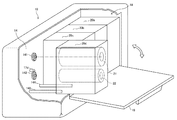
- FIG. 2 is a perspective view showing a state in which the ink ribbon cassette according to each embodiment of the present invention is attached to the printer.
- the platen roller and the thermal head are omitted.
- the printer 10 is provided with a storage unit 18 for storing the ink ribbon cassette.
- the ink ribbon cassette is attached / detached by opening the door 19 of the storage unit 18.
- FIG. 2 shows a state where the ink ribbon cassettes 20a to 20c are already mounted and the ink ribbon cassette 20d is to be mounted. *
- the plate 14 of the printer 10 is provided with a rotation shaft 141 that fits the ink ribbon supply shaft 21 and a rotation shaft 142 that fits the ink ribbon take-up shaft 22. Further, guide pins 143 and 144 for guiding the ink ribbon cassette are provided, and a pin 17d is provided at a position corresponding to the type (black) of the ink ribbon loaded in the ink ribbon cassette 20d. On the other hand, two guide holes into which guide pins 143 and 144 are inserted and a plurality of openings corresponding to a plurality of types of ink ribbons are formed on the side surface of the cassette case of the ink ribbon cassette 20d. *
- the pin 17d is located at the opening corresponding to the type (black) of the ink ribbon loaded in the ink ribbon cassette 20d. Since the ink ribbon is inserted, the ink ribbon supply shaft 21 and the ink ribbon take-up shaft 22 are unlocked in the ink ribbon cassette 20d.
- FIG. 3 is a view showing the ink ribbon cassette according to the first embodiment of the present invention.
- FIG. 3A is a side view of the ink ribbon cassette viewed from the side opposite to FIG. 1
- FIG. 3B is a side view of the ink ribbon cassette on the BB ′ plane shown in FIG.
- FIG. 3C is a cross-sectional view showing the positional relationship between the stopper of the ink ribbon cassette and the locking plate.
- an ink ribbon cassette 20a loaded with a yellow ink ribbon among the four types of ink ribbon cassettes 20a to 20d shown in FIG. 1 will be described. *
- the ink ribbon cassette 20a includes a cassette case 25 having side surfaces formed with a plurality of openings 24a to 24d at a plurality of different positions, and an unused ink ribbon.
- An ink ribbon supply shaft 21 that is rotatably supported by the cassette case 25 for supply and provided with a gear-like stopper 21a along the rotation direction, and rotates to the cassette case 25 to wind up the used ink ribbon.
- the ink ribbon take-up shaft 22 provided with a gear-like stopper 22a along the rotation direction and the ink ribbon supply shaft 21 and the ink ribbon take-up shaft 22 are locked by engaging with the stoppers 21a and 22a.
- a locking portion 26 to be included.
- the locking portion 26 includes a locking plate 261 that is rotatably supported by the cassette case 25 and a plate spring 262 that biases the locking plate 261.
- a coil spring may be used instead of the leaf spring.
- the locking plate 261 corresponds to the type of the ink ribbon 23, the engaging portion 26a that engages with the stopper 21a, the engaging portion 26b that engages with the stopper 22a. And an extended portion 26c extending to a predetermined position of the opening 24a.
- the leaf spring 262 biases the locking plate 261 so that the engaging portions 26a and 26b engage with the stoppers 21a and 22a, respectively.
- the stop plate 261 locks the ink ribbon supply shaft 21 and the ink ribbon take-up shaft 22. Accordingly, even if the ink ribbon cassette 20a is transported or the like, the ink ribbon 23 is not slackened, so that the ink ribbon 23 can be protected. In addition, if the position for mounting the ink ribbon cassette 20a is wrong, the ink ribbon supply shaft 21 and the ink ribbon take-up shaft 22 are not unlocked, and the ink ribbon supply shaft 21 and the ink ribbon take-up shaft 22 do not rotate. *
- FIG. 4 is a view showing an ink ribbon cassette according to the second embodiment of the present invention.
- 4A is a side view of the ink ribbon cassette as viewed from the opposite side to FIG. 1
- FIG. 4B is a diagram showing the positional relationship between the stopper of the ink ribbon cassette and the locking plate.
- an ink ribbon cassette 20a loaded with a yellow ink ribbon among the four types of ink ribbon cassettes 20a to 20d shown in FIG. 1 will be described. *
- the ink ribbon cassette 20a includes a cassette case 25 having side surfaces in which a plurality of openings 24a to 24d and 28a to 28d are respectively formed at a plurality of different positions, and an unused ink ribbon.
- An ink ribbon supply shaft 21 that is rotatably supported by the cassette case 25 for supply and provided with a gear-like stopper 21a along the rotation direction, and rotates to the cassette case 25 to wind up the used ink ribbon.
- the ink ribbon take-up shaft 22 provided with a gear-like stopper 22a along the rotation direction and the ink ribbon supply shaft 21 and the ink ribbon take-up shaft 22 are locked by engaging with the stoppers 21a and 22a. And a locking portion 27 to be included.
- the locking portion 27 includes a locking plate 271 that is supported by the cassette case 25 so as to be movable in parallel, and plate springs 272 and 273 that bias the locking plate 271.
- a coil spring may be used instead of the leaf spring.
- the locking plate 271 is located at the positions of an engagement portion 27a that engages with the stopper 21a, an engagement portion 27b that engages with the stopper 22a, and openings 24a and 28a that are predetermined according to the type of the ink ribbon 23.
- Each has extended portions 27c and 27d extending. *
- the leaf springs 272 and 273 bias the locking plate 271 so that the engaging portions 27a and 27b engage with the stoppers 21a and 22a, respectively.
- the locking plate 271 locks the ink ribbon supply shaft 21 and the ink ribbon take-up shaft 22. Accordingly, even if the ink ribbon cassette 20a is transported or the like, the ink ribbon 23 is not slackened, so that the ink ribbon 23 can be protected. In addition, if the position for mounting the ink ribbon cassette 20a is wrong, the ink ribbon supply shaft 21 and the ink ribbon take-up shaft 22 are not unlocked, and the ink ribbon supply shaft 21 and the ink ribbon take-up shaft 22 do not rotate. *
- two pins 17a having a tapered shape as shown in FIG. 4B are provided on the frame 14 of the printer.
- the ink ribbon cassette 20a is mounted at the correct position of the printer, as shown in FIGS. 4A and 4B, the plurality of openings 24a to 24d and 28a to 28d formed in the side surface of the cassette case 25 Since the two pins 17a provided on the printer frame 14 are inserted into the openings 24a and 28a determined in advance corresponding to the yellow ink ribbon, the pins 17a abut against the extending portions 27c and 27d. As a result, the locking plate 271 moves substantially parallel to the negative direction in the Y-axis direction, and the lock of the ink ribbon supply shaft 21 and the ink ribbon take-up shaft 22 is released. *
- FIG. 5 is a view showing an ink ribbon cassette according to the third embodiment of the present invention.
- FIG. 5A is a side view of the ink ribbon cassette viewed from the side opposite to FIG. 1
- FIG. 5B is a diagram showing the positional relationship between the stopper of the ink ribbon cassette and the locking plate.
- an ink ribbon cassette 20a loaded with a yellow ink ribbon among the four types of ink ribbon cassettes 20a to 20d shown in FIG. 1 will be described. *
- the ink ribbon cassette 20a is provided with a cassette case 25 having a side surface in which a plurality of openings 24a to 24d are formed at a plurality of different positions, and an unused ink ribbon.
- An ink ribbon supply shaft 21 that is rotatably supported by the cassette case 25 and provided with a gear-like stopper 21a along the rotation direction, and is rotatably supported by the cassette case 25 to wind up the used ink ribbon.
- the ink ribbon take-up shaft 22 provided with a gear-like stopper 22a along the rotation direction, and the engaging portion that engages with the stoppers 21a and 22a to lock the ink ribbon supply shaft 21 and the ink ribbon take-up shaft 22 29.
- the locking portion 29 includes a locking plate 291 that is supported by the cassette case 25 so as to be movable in parallel, and a coil spring 292 that biases the locking plate 291.
- a plate spring may be used instead of the coil spring.
- the locking plate 291 includes an engagement portion 29a that engages with the stopper 21a, an engagement portion 29b that engages with the stopper 22a, and a position of at least one opening 24a that is predetermined according to the type of the ink ribbon 23. Extending part 29c. *
- the coil spring 292 biases the locking plate 291 so that the engaging portions 29a and 29b engage with the stoppers 21a and 22a, respectively.
- the stop plate 291 locks the ink ribbon supply shaft 21 and the ink ribbon take-up shaft 22. Accordingly, even if the ink ribbon cassette 20a is transported or the like, the ink ribbon 23 is not slackened, so that the ink ribbon 23 can be protected. In addition, if the position for mounting the ink ribbon cassette 20a is wrong, the ink ribbon supply shaft 21 and the ink ribbon take-up shaft 22 are not unlocked, and the ink ribbon supply shaft 21 and the ink ribbon take-up shaft 22 do not rotate. *
- a pin 17a having a tapered shape as shown in FIG. 5B is provided on the frame 14 of the printer.
- yellow ink is discharged from the plurality of openings 24a to 24d formed on the side surface of the cassette case 25. Since the pin 17a provided on the printer frame 14 is inserted into the predetermined opening 24a corresponding to the ribbon, the locking plate 291 is moved in the Z-axis direction by the pin 17a coming into contact with the extending portion 29c.
- the ink ribbon supply shaft 21 and the ink ribbon take-up shaft 22 are unlocked.
- the locking portion serves both as an ink ribbon slack prevention mechanism and a mounting position detection mechanism, and thus a simple mechanism prevents ink ribbon slack and erroneous printing. can do. Further, since the mold of the cassette case made of resin or the like can be made common to a plurality of types of ink ribbons, an increase in cost when the present invention is implemented can be suppressed.
Landscapes
- Impression-Transfer Materials And Handling Thereof (AREA)
- Electronic Switches (AREA)
Abstract
Selon l'invention, avec un mécanisme simple, le mou d'un ruban encreur peut être empêché lorsqu'une cassette de ruban encreur n'est pas fixée à une imprimante couleur, et des erreurs d'impression peuvent être empêchées même si la position de la cassette de ruban encreur est erronée lorsque la cassette est fixée à l'imprimante couleur. Une cassette de ruban encreur comporte une enceinte de cassette, comprenant une pluralité d'ouvertures disposées en une pluralité de positions différentes ; un arbre d'alimentation en ruban encreur et un arbre d'enroulement de ruban encreur supportés de façon à pouvoir tourner par l'enceinte de cassette et comportant un élément d'arrêt du type à engrenages dans la direction de rotation ; et une partie de verrouillage qui verrouille l'arbre d'alimentation en ruban encreur et l'arbre d'enroulement de ruban encreur par mise en prise avec l'élément d'arrêt, et qui libère le verrouillage de l'arbre d'alimentation en ruban encreur et de l'arbre d'enroulement de ruban encreur lorsqu'au moins une broche est insérée dans au moins une ouverture qui a été déterminée comme correspondant à un type du ruban encreur, parmi la pluralité d'ouvertures formées sur l'enceinte de cassette.
Applications Claiming Priority (2)
| Application Number | Priority Date | Filing Date | Title |
|---|---|---|---|
| JP2010-076252 | 2010-03-29 | ||
| JP2010076252A JP5502555B2 (ja) | 2010-03-29 | 2010-03-29 | インクリボンカセット及びそれを用いるカラープリンタ |
Publications (1)
| Publication Number | Publication Date |
|---|---|
| WO2011121684A1 true WO2011121684A1 (fr) | 2011-10-06 |
Family
ID=44711481
Family Applications (1)
| Application Number | Title | Priority Date | Filing Date |
|---|---|---|---|
| PCT/JP2010/006214 Ceased WO2011121684A1 (fr) | 2010-03-29 | 2010-10-20 | Cassette de ruban encreur et imprimante couleur l'utilisant |
Country Status (2)
| Country | Link |
|---|---|
| JP (1) | JP5502555B2 (fr) |
| WO (1) | WO2011121684A1 (fr) |
Citations (9)
| Publication number | Priority date | Publication date | Assignee | Title |
|---|---|---|---|---|
| JPS59156756A (ja) * | 1983-02-25 | 1984-09-06 | Ricoh Co Ltd | インクカ−トリツジ装填装置 |
| JPS61120552U (fr) * | 1985-01-16 | 1986-07-30 | ||
| JPH0323970A (ja) * | 1989-06-20 | 1991-01-31 | Mitsubishi Electric Corp | サーマルラインプリンタ |
| JPH04193554A (ja) * | 1990-11-27 | 1992-07-13 | Ricoh Co Ltd | サーマルカラープリンタ |
| JPH10193730A (ja) * | 1996-12-27 | 1998-07-28 | Victor Co Of Japan Ltd | インクシートカセット |
| JP2002096517A (ja) * | 2000-09-25 | 2002-04-02 | Sony Corp | インクリボンカートリッジ |
| JP2004188810A (ja) * | 2002-12-12 | 2004-07-08 | Pilot Corporation | インクリボンコア |
| JP2006062278A (ja) * | 2004-08-30 | 2006-03-09 | Alps Electric Co Ltd | インクリボンカセットおよびこれを用いたプリンタ装置 |
| JP2007230157A (ja) * | 2006-03-02 | 2007-09-13 | Sony Corp | プリンタ装置 |
-
2010
- 2010-03-29 JP JP2010076252A patent/JP5502555B2/ja not_active Expired - Fee Related
- 2010-10-20 WO PCT/JP2010/006214 patent/WO2011121684A1/fr not_active Ceased
Patent Citations (9)
| Publication number | Priority date | Publication date | Assignee | Title |
|---|---|---|---|---|
| JPS59156756A (ja) * | 1983-02-25 | 1984-09-06 | Ricoh Co Ltd | インクカ−トリツジ装填装置 |
| JPS61120552U (fr) * | 1985-01-16 | 1986-07-30 | ||
| JPH0323970A (ja) * | 1989-06-20 | 1991-01-31 | Mitsubishi Electric Corp | サーマルラインプリンタ |
| JPH04193554A (ja) * | 1990-11-27 | 1992-07-13 | Ricoh Co Ltd | サーマルカラープリンタ |
| JPH10193730A (ja) * | 1996-12-27 | 1998-07-28 | Victor Co Of Japan Ltd | インクシートカセット |
| JP2002096517A (ja) * | 2000-09-25 | 2002-04-02 | Sony Corp | インクリボンカートリッジ |
| JP2004188810A (ja) * | 2002-12-12 | 2004-07-08 | Pilot Corporation | インクリボンコア |
| JP2006062278A (ja) * | 2004-08-30 | 2006-03-09 | Alps Electric Co Ltd | インクリボンカセットおよびこれを用いたプリンタ装置 |
| JP2007230157A (ja) * | 2006-03-02 | 2007-09-13 | Sony Corp | プリンタ装置 |
Also Published As
| Publication number | Publication date |
|---|---|
| JP2011207012A (ja) | 2011-10-20 |
| JP5502555B2 (ja) | 2014-05-28 |
Similar Documents
| Publication | Publication Date | Title |
|---|---|---|
| JP6247011B2 (ja) | 印刷装置 | |
| US9925795B2 (en) | Media processing device with enhanced media and ribbon loading and unloading features | |
| KR101532396B1 (ko) | 프린트 헤드 조립체를 가진 프린터, 클러치 조립체, 및 프린터 리본 운반 조립체 | |
| CN108778762B (zh) | 带盒 | |
| WO2019065655A1 (fr) | Imprimante | |
| JP5946325B2 (ja) | センサ移動装置 | |
| WO2013121656A1 (fr) | Imprimante | |
| WO2018066154A1 (fr) | Imprimante | |
| JP5502555B2 (ja) | インクリボンカセット及びそれを用いるカラープリンタ | |
| EP3228470B1 (fr) | Imprimante | |
| JP2022100408A (ja) | プリンタ | |
| CN111108001A (zh) | 打印机 | |
| JP4632896B2 (ja) | プリンタおよびセンサユニット | |
| US9481183B2 (en) | Printer | |
| JP2014008620A (ja) | プリンタ | |
| JP6639715B1 (ja) | プリンタ | |
| CN104972773A (zh) | 印刷装置 | |
| JP2013136431A (ja) | 媒体搬送機構、プリンタ | |
| JP5350435B2 (ja) | プリンタおよびプリンタの使用方法 | |
| JPH0834127A (ja) | カラー印刷装置 | |
| JP2015077688A (ja) | インクリボンカセット及び熱転写式カラープリンタ | |
| JP2013132754A (ja) | 熱転写カラープリンター | |
| JP2013216417A (ja) | 媒体ガイド装置 | |
| JP2012187796A (ja) | プリンタ | |
| JP2013095019A (ja) | インクリボンカセット |
Legal Events
| Date | Code | Title | Description |
|---|---|---|---|
| 121 | Ep: the epo has been informed by wipo that ep was designated in this application |
Ref document number: 10848866 Country of ref document: EP Kind code of ref document: A1 |
|
| NENP | Non-entry into the national phase |
Ref country code: DE |
|
| 122 | Ep: pct application non-entry in european phase |
Ref document number: 10848866 Country of ref document: EP Kind code of ref document: A1 |