WO2011121804A1 - Canne - Google Patents
Canne Download PDFInfo
- Publication number
- WO2011121804A1 WO2011121804A1 PCT/JP2010/059900 JP2010059900W WO2011121804A1 WO 2011121804 A1 WO2011121804 A1 WO 2011121804A1 JP 2010059900 W JP2010059900 W JP 2010059900W WO 2011121804 A1 WO2011121804 A1 WO 2011121804A1
- Authority
- WO
- WIPO (PCT)
- Prior art keywords
- cane
- cane body
- rubber chip
- button
- grip
- Prior art date
- Legal status (The legal status is an assumption and is not a legal conclusion. Google has not performed a legal analysis and makes no representation as to the accuracy of the status listed.)
- Ceased
Links
Images



Classifications
-
- A—HUMAN NECESSITIES
- A45—HAND OR TRAVELLING ARTICLES
- A45B—WALKING STICKS; UMBRELLAS; LADIES' OR LIKE FANS
- A45B9/00—Details
- A45B9/02—Handles or heads
-
- A—HUMAN NECESSITIES
- A45—HAND OR TRAVELLING ARTICLES
- A45B—WALKING STICKS; UMBRELLAS; LADIES' OR LIKE FANS
- A45B9/00—Details
- A45B9/04—Ferrules or tips
-
- A—HUMAN NECESSITIES
- A45—HAND OR TRAVELLING ARTICLES
- A45B—WALKING STICKS; UMBRELLAS; LADIES' OR LIKE FANS
- A45B9/00—Details
- A45B2009/005—Shafts
Definitions
- the present invention relates to a cane, and more particularly to a cane for walking assistance.
- a cane equipped with a length adjusting device As a cane whose length can be adjusted steplessly, for example, there is a cane equipped with a length adjusting device.
- a screw body having a screw shaft integrally protruding at the center of a conical body having a conical circumferential surface is fixed to the upper end of the lower pipe, and the screw shaft of the screw body is expanded in the circumferential direction.
- the provided cylindrical braking member is screwed together.
- an eccentric rotating cam disk is provided, and the lower pipe is rotated so that the cam disk is brought into pressure contact with the inner peripheral surface of the upper pipe to brake the upper pipe without turning.
- the upper pipe and the lower pipe are fixed by expanding the braking member on the conical circumferential surface of the cone and press-contacting it with the inner circumferential surface of the upper pipe.
- Patent Document 1 neither describes nor suggests how to deal with the case where the rubber tip provided at the lower end of the lower pipe is worn. Usually, a specific part of the rubber chip is in contact with the ground or the like, so that only that part is worn. In such a case, replacement of the rubber chip is forced in a relatively short time. This is not preferable from the viewpoint of ecology.
- an object of the present invention is to provide a cane that can effectively use a rubber chip.
- the walking stick of the present invention is A gripping part located at the upper end of the cane body; A rubber chip located at the lower end of the cane body; A rotating part for rotating the grip part and the rubber chip in four stages; A fixing portion for fixing the gripping portion and the rubber chip after the rotation portion is rotated by the rotation portion;
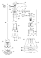
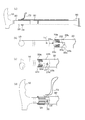
- FIG.1 (a) is a schematic diagram of the cane of Embodiment 1 of this invention.
- FIG. 1B is a cross-sectional view of the vicinity of the button 32 in FIG.
- FIG.1 (c) is sectional drawing of the button 52 vicinity of Fig.1 (a).
- the grip portion 10 is located at the upper end.
- a pipe-shaped first cane body 20 is connected to the lower side of the grip 10.
- the first cane body 20 is provided with a plurality of holes 22, 24, and 26 along the axial direction thereof.
- the pipe-shaped second cane body 30 is located in the first cane body 20, and the third cane body 50 is located in the second cane body 30.
- a button 32 to be fitted into any of the plurality of holes 22, 24, 26 and a spring 34 for defining the position of the button 32 are provided on the upper part of the second cane body 30, a button 32 to be fitted into any of the plurality of holes 22, 24, 26 and a spring 34 for defining the position of the button 32 are provided. What is necessary is just to determine the position which fits the button 32 according to the length of the cane requested
- FIG. 1B shows a state where the button 32 is fitted in the hole. If the button 32 fits in any of the holes 22, 24, 26, the connection between the first cane body 20 and the second cane body 30 is achieved. However, the first cane body 20 and the second cane body 30 are connected so that the connection between the first cane body 20 and the second cane body 30 is not released due to an unexpected external force applied to the button 32.
- the cap 40 which maintains these connection is attached to the part.
- the upper part of the third cane body 50 is provided with a button 52 to be fitted in any of the plurality of holes (recesses) 36a to 36d and a spring 54 for defining the position of the button 52. What is necessary is just to determine the position which fits the button 52 according to the weight reduction of the bottom part of the rubber chip 60.
- FIG. 1 (c) shows a state in which the button (convex portion) 52 is fitted in the hole 36d.
- the button 52 is fitted into any of the holes 36a to 36d, the connection between the second cane body 30 and the third cane body 50 is achieved.
- the holes 36a to 36d are arranged circumferentially in the second cane body 30.
- a rubber chip 60 is attached to the lower end of the third cane body 50.
- the rubber chip 60 has a groove 68 that receives the third cane body 50.
- notification areas 62, 64, and 66 with different colors are formed on the side surface of the rubber chip 60.
- the button 52 is pressed to rotate the rubber tip 60 side and the third cane body 50 by, for example, 90 degrees, so that the holes 36a to 36d Exchange the position of the button 52.
- the cane typically, if the cane is used for a while after being rotated three times, all of the notification area 66 is worn out.
- the button 52 is pressed, and the rubber chip 60 side and the third cane body 50 are moved to, for example, 90 degrees ( (Or 180 degrees), and the position of the button 52 with respect to the holes 36a to 36d may be exchanged.
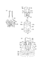
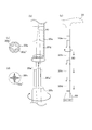
- FIG. 2 (a) is typical sectional drawing of the cane of Embodiment 2 of this invention.
- FIG. 2B is an enlarged side view of the fastening portion (convex portion) 12 of FIG.
- FIG. 2C is an exploded perspective view of the vicinity of the grip portion 10 of FIG. 2 (d) to 2 (f) are explanatory diagrams of the rubber chip 60 of FIG. 2 (a).
- the cane shown in FIG. 2 (a) is largely different from the one shown in FIG. 1 in the following two points. That is, first, in the present embodiment, the grip portion 10 and the first cane body 20 are configured to rotate relative to each other. Second, a metal replacement notification plate 92 is provided in the rubber chip 60.
- the grip portion 10 has a first opening that is relatively large on the side connected to the first cane body 20 and is orthogonal to the opening direction of the first opening on the upper side of the drawing of the first opening. A relatively small second opening is formed.
- the receiving portion 14 is attached to the first opening via an adhesive or the like.
- a screw hole is formed in the second opening, and a fastening portion 12 having a threaded shaft portion is attached to the second opening.
- a knob portion 12a is attached to the opposite side of the shaft portion of the retaining portion 12 so as to stand when the retaining portion 12 rotates and to be tilted when the cane is used.
- the upper portion of the receiving portion 14 is formed with a constriction, and a plurality of (for example, four) groove portions (concave portions) 14a are formed here.
- the fastening portion 12 and the receiving portion 14 are coupled by receiving the tip of the shaft portion of the fastening portion 12 by any one of the groove portions 14a formed in the constricted portion.
- a first connecting part 16 is attached to the lower end of the receiving part 14 via a base part 18.
- the upper side of the base 18 is fixed to the bottom of the grip 10 with an adhesive or the like.
- the first connecting portion 16 has a screw hole formed in the bottom portion, and realizes the connection between the grip portion 10 and the first cane body 20 together with the second connecting portion 27 on the first cane body 20 side.
- the second linking portion 27 is attached to the upper portion of the first cane body 20 via an adhesive or the like or by press fitting.
- a screw portion extending upward is formed at the center upper end of the second connecting portion 27, and the screw portion is screwed into the screw hole of the first connecting portion 16.
- a device for maintaining the connection between the first connecting portion 16 and the second connecting portion 27 is devised. Specifically, first, a threaded portion is formed on the outer periphery of the lower end of the base portion 18. On the other hand, a cap portion 28 is disposed on the outer periphery of the second connecting portion 27, and a threaded portion is formed on the inner peripheral portion. Therefore, by connecting these threaded portions to each other, the first connecting portion 16 and the second connecting portion 27 are prevented from loosening each other.
- a cane body receiving portion 69 in which the replacement notification plate 92 is located at the bottom is provided in the rubber chip 60 at the stage of manufacturing the rubber chip 60.
- the rubber chip 60 is manufactured using, for example, a mold or the like in which the replacement notification plate 92 and the fastening portion of the cane body receiving portion 69 are formed.
- a screw hole is formed in the upper center of the cane body receiving portion 69.
- the bottom surface of the replacement notification plate 92 is formed with a mesh so as not to slip when contacting the ground or the like even when the rubber chip 60 is exposed due to wear.
- a metal sound is generated due to contact between the replacement notification plate 92 and the ground or the like, so that replacement of the rubber chip 60 can be promoted.
- the third connecting portion 38 is attached to the lower end of the second cane body 30 via an adhesive or the like or by press fitting.
- a screw part is formed at the center lower part of the third connecting part 38, and mutual connection is realized by screwing with the cane body receiving part 69.
- the bottom end portion of the third cane body 30 may be threaded and a screw hole may be formed in the inner wall of the cane body receiving portion 69 without providing the third connecting portion 38.
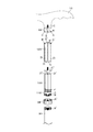
- FIG. 3 is typical sectional drawing of the downward direction of the cane of Embodiment 3 of this invention.
- FIG. 3B is an enlarged view of the vicinity of the buttons 61a and 61b (convex portions) in FIG.
- FIG.3 (c) is an expansion perspective view of the rotation assistance part 31 of Fig.3 (a).
- FIG. 3D is an enlarged perspective view near the rubber chip 60 of FIG.
- the cane of this embodiment is configured such that the second cane body 30 and the rubber chip 60 rotate relative to each other.
- this cane allows the second cane body 30 and the rubber tip 60 to rotate relative to each other by pressing the buttons 61 a and 61 b through the side surfaces of the rubber tip 60.
- the rubber chip 60 is formed with a stepped cylindrical cavity, and a rotation assisting portion 31 made of rubber or resin is attached to the upper portion thereof by press fitting or the like.
- a through hole is formed in the center of the bottom of the rotation assisting portion 31, and the rubber chip 60 and the second cane body 30 are screwed to each other by a screw 65 via the through hole.
- buttons 61a and 61b are received by two opposing holes.
- the positions of the buttons 61 a and 61 b are defined by a spring 75.
- a screw receiving portion 63 to be screwed with the screw 65 is press-fitted into the bottom portion of the second cane body 30.
- depressions 31a and 31b are formed on the slope of the rubber chip 60 at positions corresponding to the buttons 61a and 61b so that the buttons 61a and 61b can be easily pressed.
- the rotation assisting portion 31 is formed with a substantially cylindrical cavity.
- a through hole 37 through which the screw 65 passes is formed at the bottom of the substantially cylindrical cavity, and button receiving portions 35a to 35d for receiving the buttons 61a and 61b when the wand is used are formed at the top of the substantially cylindrical cavity.
- the button receiving portions 35a to 35d are slightly larger recesses than the buttons 61a and 61b, and the distal ends of the buttons 61a and 61b are guided between the button receiving portions 35a to 35d when the second cane body 30 and the rubber chip 60 are rotated. It connects with the groove part 33 to do.
- buttons 61a and 61b are received by the button receiving portions 35a and 35c before the rotation, the tips of the buttons 61a and 61b pass through the groove portion 33 by the rotation, and the button It will reach the receiving portions 35b and 35d. At this time, the buttons 61a and 61b advance in a direction in which they repel each other by the spring 75, and are received by the button receiving portions 35b and 35d.
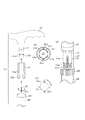
- FIG.4 (a) is a typical exploded sectional view of the upper part of the cane of Embodiment 4 of this invention.
- the cane of the present embodiment is configured such that the grip portion 10 and the first cane body 20 rotate with respect to each other.
- FIG. 4D is a schematic perspective view above the cane of the present embodiment.
- FIG.4 (c) is sectional drawing of the nail
- FIG. 4D is a cross-sectional view of the claw portion 21c of FIG.
- a receiving portion 11 is connected to the lower end of the grip portion 10.
- the receiving part 11 has four pieces 11a to 11d having a tapered shape whose tip is thin as a whole.
- the cane body pieces 11a to 11d receive the claw portions 21c and 21d between the pieces (concave portions).
- the outer surfaces of the pieces 11a to 11d are threaded and screwed with a screw portion 13 described below.
- the screw portion 13 has a substantially cylindrical shape, and the middle stage of the inner wall has a shape corresponding to the tapered shape of the piece portions 11a to 11d.
- the middle portion of the inner wall has a screw shape with the pieces 11a to 11d.
- a threaded portion to be joined is formed.
- a threaded portion 13b for receiving a cap portion 23 to be described below is formed at the lower portion of the outer wall of the threaded portion 13.
- the cane of this embodiment includes a claw portion 21c between the pieces 11a and 11b and a claw between the pieces 11c and 11c.
- the threaded portion 13 is screwed into the receiving portion 11 in such a manner that 21d is located.
- the pieces 11 a to 11 d of the receiving portion 11 are tightened toward the axial center of the receiving portion 11 by the inner wall of the screw portion 13.
- the claw portion 21c is sandwiched between the pieces 11a and 11b, and the claw portion 21d is sandwiched between the pieces 11c and 11d, so that the grip portion 10 and the first cane body 20 can be coupled.
- cap part 23 bears the role which maintains the coupling
- the grip portion 10 and the first cane body 20 are mutually rotated, for example, about 90 degrees.
- the grip 10 and the first cane body 20 are fitted again. If it does so, claw part 21c will be located between piece parts 11a and 11d, and claw part 21d will be located between piece parts 11b and 11d.
- the claw portion 21c is sandwiched between the pieces 11a and 11d, and the claw portion 21d is sandwiched between the pieces 11b and 11d. Then, the cap part 23 is tightened.
- FIG. 5A is a schematic exploded cross-sectional view above the cane of the fifth embodiment of the present invention.
- the cane of the present embodiment is configured such that the grip portion 10 and the first cane body 20 rotate with respect to each other.
- FIG.5 (b) is a typical perspective view of the cover 70 with which the cane of Fig.5 (a) is mounted
- FIG.5 (d) is a perspective view of the upper part of Fig.5 (a).
- FIG.5 (c) is an expanded sectional view of cover 70 vicinity of Fig.5 (a).
- FIG.5 (e) is sectional drawing of the button 17 (convex part) vicinity of FIG.5 (c).
- the grip portion 10 includes a button 17 for rotating the grip portion 10 and the first cane body 20, and a spring 19 that defines the position of the button 17.
- the first cane body 20 is provided with a cover 70 that prevents the external force from being applied by covering the button 17.
- the cover 70 is attached with a string 72 for detaching it from the first cane body 20.
- FIG. 5 (b) recesses 74, 76 and 78 corresponding to the buttons 17 are formed on the inner wall of the cover 70.
- the number of depressions on the inner wall of the cover 70 is three as an example, and as long as at least one depression is formed, it may be more or less than this.
- the reason why the number of depressions is three in the present embodiment is to facilitate the positioning of any depression and the button 17 when the cover 70 is attached.
- FIG. 5C shows a state where the recess 78 and the button 17 are well aligned.
- FIG. 5 (e) corresponds to FIG. 1 (c), and also in this embodiment, the grip portion 10 and the first cane body 20 are rotated while the button 17 is pressed.
- the installation position of the rubber chip 60 with the ground or the like can be changed.
- FIG. 1 In addition, it may replace with the button 17 and the spring 19 which are shown to Fig.5 (a) etc., and you may provide the axial part (convex part) 71 in the cap 70.
- FIG. 1 at least one set of through-holes (here, two sets of through-holes) through which the shaft portion 71 passes are formed at predetermined positions of the gripping portion 10, and the first cane body 20 also includes the corresponding What is necessary is just to form two sets of through-holes which the axial part 71 passes in the position corresponding to a through-hole. Even in such a case, the shaft portion 71 may be once extracted from the through hole, and the grip portion 10 and the first cane body 20 may be rotated by 90 degrees, for example, and then the shaft portion 71 may be inserted into the through hole again.
- the auxiliary cap 13 for preventing the cap 70 from falling off the wand is used. Specifically, the cap 70 is covered with the auxiliary cap 13.
- the auxiliary cap 13 is provided with a lever 13a for tightening and releasing the cap 70. If the lever 13a is parallel to the axial direction of the cane about the rotation shaft 13b, the auxiliary cap 13 is tightened to the cap 70. If the lever 13a is orthogonal to the axial direction of the cane, the cap 70 is released from tightening.
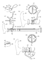
- FIG.6 (a) is typical sectional drawing of the cane of Embodiment 6 of this invention.
- the cane of the present embodiment is configured such that the grip portion 10 and the first cane body 20 rotate with respect to each other.
- FIG.6 (d) is a typical perspective view above the cane of this embodiment.
- 6 (b) and 6 (c) are explanatory diagrams of a method for connecting the grip 10 and the first cane body 20 of FIG. 6 (d).
- the cane of the present embodiment is also provided with a cover 70 on the first cane body 20 as in the fifth embodiment. Further, in the vicinity of the cover 70, a maintenance cap 29 for maintaining the connection between the grip portion 10 and the first cane body 20 is located.
- the grip portion 10 is provided with a convex portion 15 ′.
- the convex portion 15 ′ has a function corresponding to the button 17. That is, the convex part 15 ′ is a part for realizing the rotation of the grip part 10 and the first cane body 20.
- the first cane body 20 is formed with, for example, four guide portions 23a, 23c, 23e, and 23g into which the convex portion 15 ′ is inserted.
- the guide portion 23a and the like are slightly wider than the diameter of the convex portion 15 ′.
- Convex portion receivers (concave portions) 23b, 23d, 23f, and 23h are integrally formed on the guide portion 23a and the like.
- Convex part receiver 23b etc. are convex part 15 ' It is said to be slightly narrower than the diameter.
- FIG. 6 shows an example in which the grip portion 10 is provided with a convex portion 15 ′, and the guide portion 23 a and the like are formed on the first cane body 20. 23a etc. may be formed and convex part 15 'may be provided in the 1st cane main body 20.
- FIG. 6 shows an example in which the grip portion 10 is provided with a convex portion 15 ′, and the guide portion 23 a and the like are formed on the first cane body 20. 23a etc. may be formed and convex part 15 'may be provided in the 1st cane main body 20.
- FIG.7 (a) is typical sectional drawing of the cane of Embodiment 7 of this invention.
- a so-called folding cane is shown.
- a first cane body 20 a to a fourth cane body 20 d are sequentially connected to the grip portion 10.
- the grip portion 10 and the cane body 20d are connected by rubber 90.
- the first cane body 20a and the second cane body 20b are pulled, the second cane body 20b and the third cane body 20c are pulled, the third cane body 20c and the fourth cane body 20d are pulled, Each can be folded. At this time, due to the presence of the rubber 90, the parts constituting the cane are not separated. When assembling the cane, this series of operations may be reversed.
- FIG. 7B is an exploded perspective view of a connecting portion between the first cane body 20a and the second cane body 20b.
- FIG.7 (c) is sectional drawing by the side of the 1st cane main body 20a of FIG.7 (b).
- FIG.7 (d) is sectional drawing by the side of the 2nd cane main body 20b of FIG.7 (b).
- FIGS. 7B and 7C four rail-like protruding portions (convex portions) 20a 'are formed on the inner wall of the end portion of the first cane body 20a.
- four pieces (concave portions) 20b ′ for receiving the protruding portion 20a ′ are formed at the end of the first cane body 20a.
- the numbers of the protruding portions 20a 'and the piece portions 20b' are merely examples, and may be more or less than this.
- connection part of the 2nd cane body 20b and the 3rd cane body 20c and the connection part of the 3rd cane body 20c and the 4th cane body 20d are also as the structure similar to FIG.7 (b).
- at least one of the connecting portions including the connecting portion between the first cane body 20a and the second cane body 20b may have a structure as shown in FIG. In such a case, the other connecting parts may be firmly connected at the time of connection so that they do not rotate with each other when the wand is used.
- the present invention is not limited to those shown in FIGS. 7 and 8 as long as the rotation between any of the cane bodies and the subsequent rotation maintenance can be realized.
- FIG. 9 is a schematic exploded perspective view of a cane according to Embodiment 8 of the present invention.
- the wand shown in FIG. 9 is provided with, for example, four convex portions E on the bottom surface of the base portion 18 located at the lower end of the grip portion 10. Further, a screw hole C for receiving a shaft portion C ′ described later is formed at the center of the lower end of the grip portion 10.
- a pipe-shaped socket 120 is located below the grip 10. For example, four guide grooves D along the axial direction are formed on the inner wall of the socket 120. Further, the socket 120 is formed with a concave portion E ′ for receiving the convex portion E at the upper end.
- a cylindrical socket receiver 100 is located below the socket 120.
- the socket receiver 100 has a shaft portion C ′ extending from the center of the upper surface to information.
- a rail portion D ′ is formed on the side surface of the socket receiver 100 at a position corresponding to the guide groove D.
- the socket receiver 100 is configured such that the spring F is located at the bottom.
- the lower end of the spring F is defined by the pedestal 110 of the socket receiver 100.
- the pedestal 110 has a threading A for receiving the cap 28 on the outer wall, and a threading B for receiving the first cane body 20 on the inner wall.
- the cap 28 receives the lower end of the socket 120 at its upper end.
- the inner wall of the cap 28 is screwed with the threading A of the pedestal 110.
- the cap 28 prevents the socket 120 from sliding downward when an unexpected external force is applied to the socket 120 from above.
- the first cane body 20 is the same as that of the above-described embodiment, but here, a threading B ′ to be screwed with the threading B of the base 110 is formed.
- the grip portion 10 and the socket receiver 100 are connected through the screw hole C and the shaft portion C ′.
- the socket 120 is pushed upward by the spring F, and the convex portion E of the base portion 18 and the concave portion E ′ of the socket 120 are coupled in a aligned state. Therefore, in normal times, the gripping portion 10 and the socket receiver 100 do not rotate relative to each other.
- the socket 120 is received by the socket receiver 100.
- the socket 120 and the socket receiver are normally used. 100 does not rotate relative to each other.
- the socket receiver 100 is coupled to the first cane body 20 through the pedestal 110, the socket receiver 100 and the first cane body 20 do not rotate relative to each other. That is, at the normal time, the respective parts shown in FIG. 9 do not rotate relative to each other.
- FIG. 10 is a schematic exploded perspective view of a cane according to Embodiment 9 of the present invention.
- FIG. 10 shows an exploded perspective view near the rubber chip 60.
- a cane as shown in FIG. 10 is suitable when the rubber chip 60 is replaced.
- the cane shown in FIG. 10 is provided with a cap 28 in which a threaded portion A ′ is formed on the inner wall near the lower end of the second cane body 20, and the threaded portion B is formed on the lower end outer wall of the second cane body 20.
- the rotation assisting part 31 embedded in the rubber chip 60 at the time of manufacture is formed with a threaded part A that is screwed to the cap 28 on the upper outer wall and a threaded part B ′ that is screwed to the threaded part B on the inner wall.
- several claw portions 3A to 3C for preventing rotation with the rubber chip 60 are formed on the outer wall of the rotation assisting portion 31.
- the cane shown in FIG. 10 screws the second cane body 20 and the rotation assisting part 31 with the threaded part B and the threaded part B '.
- the cap 28 is tightened to prevent the threaded portion B and the threaded portion B 'from loosening. Then, when the rubber tip 60 is worn by use of the cane and the replacement notification plate 92 is exposed after changing the contact surface between the rubber tip 60 and the ground several times as described above, If the cap 28 is loosened and the threaded portion B and the threaded portion B ′ are loosened, the cap 28 can be easily replaced.
Landscapes
- Walking Sticks, Umbrellas, And Fans (AREA)
- Rehabilitation Tools (AREA)
Abstract
Priority Applications (5)
| Application Number | Priority Date | Filing Date | Title |
|---|---|---|---|
| EP10848977A EP2415367A4 (fr) | 2010-03-29 | 2010-06-11 | Canne |
| US13/130,419 US8851094B2 (en) | 2010-03-29 | 2010-06-11 | Cane |
| CA2756488A CA2756488C (fr) | 2010-03-29 | 2010-06-11 | Canne |
| CN2010800028577A CN102762122A (zh) | 2010-03-29 | 2010-06-11 | 手杖 |
| US13/910,614 US20130263902A1 (en) | 2010-03-29 | 2013-06-05 | Cane |
Applications Claiming Priority (2)
| Application Number | Priority Date | Filing Date | Title |
|---|---|---|---|
| JP2010-075772 | 2010-03-29 | ||
| JP2010075772A JP4530377B1 (ja) | 2010-03-29 | 2010-03-29 | 杖 |
Related Child Applications (2)
| Application Number | Title | Priority Date | Filing Date |
|---|---|---|---|
| US13/130,419 A-371-Of-International US8851094B2 (en) | 2010-03-29 | 2010-06-11 | Cane |
| US13/910,614 Division US20130263902A1 (en) | 2010-03-29 | 2013-06-05 | Cane |
Publications (1)
| Publication Number | Publication Date |
|---|---|
| WO2011121804A1 true WO2011121804A1 (fr) | 2011-10-06 |
Family
ID=42767918
Family Applications (1)
| Application Number | Title | Priority Date | Filing Date |
|---|---|---|---|
| PCT/JP2010/059900 Ceased WO2011121804A1 (fr) | 2010-03-29 | 2010-06-11 | Canne |
Country Status (7)
| Country | Link |
|---|---|
| US (2) | US8851094B2 (fr) |
| EP (2) | EP2526806A1 (fr) |
| JP (1) | JP4530377B1 (fr) |
| CN (1) | CN102762122A (fr) |
| CA (1) | CA2756488C (fr) |
| TW (1) | TWI488597B (fr) |
| WO (1) | WO2011121804A1 (fr) |
Families Citing this family (11)
| Publication number | Priority date | Publication date | Assignee | Title |
|---|---|---|---|---|
| JP4612115B1 (ja) * | 2010-06-11 | 2011-01-12 | 株式会社丸冨士 | 杖用ゴムチップ及びそれが取り付けられた杖 |
| FR3001397B1 (fr) * | 2013-01-31 | 2015-03-27 | Salomon Sas | Embout amovible de baton |
| FR3008608A1 (fr) * | 2013-07-22 | 2015-01-23 | Daniel Levasseur | Embout de securite pour canne, et canne comportant un tel embout |
| US10092067B2 (en) * | 2014-10-15 | 2018-10-09 | Michael Graves Design Group, Inc. | Walking stick |
| JP5972342B2 (ja) * | 2014-11-29 | 2016-08-17 | 株式会社Revo | 多点杖 |
| US10813421B2 (en) * | 2019-01-18 | 2020-10-27 | Vision Sports Enterprise Co., Ltd. | End cap structure for cane/crutch/trekking pole |
| USD930969S1 (en) * | 2019-03-28 | 2021-09-21 | Avenue Mobility Ltd. | Folding cane |
| CN112298442B (zh) * | 2019-07-15 | 2023-01-31 | 捷安特电动车(昆山)有限公司 | 自行车锁具 |
| USD944511S1 (en) * | 2020-02-18 | 2022-03-01 | Orthoglam Inc. | Cane |
| US11432626B2 (en) * | 2020-03-04 | 2022-09-06 | Inventive Solutions LLC | Two-in-one walking support and methods of use |
| US12491810B2 (en) * | 2022-05-20 | 2025-12-09 | Meera RAMASWAMI | Vehicle access mobility tool |
Citations (5)
| Publication number | Priority date | Publication date | Assignee | Title |
|---|---|---|---|---|
| JPH0372715U (fr) * | 1989-11-17 | 1991-07-23 | ||
| JPH10225313A (ja) * | 1997-02-18 | 1998-08-25 | Marutoku:Kk | 杖 |
| JP2002112815A (ja) * | 2000-10-10 | 2002-04-16 | Numata Seisakusho:Kk | 屋内・外兼用杖 |
| JP2003164309A (ja) * | 2001-11-30 | 2003-06-10 | Hyogo Prefectural Social Walfare Corp | 杖用石突 |
| JP2006280837A (ja) * | 2005-04-05 | 2006-10-19 | Aomori Prefecture | 転倒しにくい杖 |
Family Cites Families (17)
| Publication number | Priority date | Publication date | Assignee | Title |
|---|---|---|---|---|
| US1197375A (en) * | 1915-12-22 | 1916-09-05 | Weldon A L Hoff | Adjustable crutch-tip. |
| US4411284A (en) * | 1981-11-19 | 1983-10-25 | Opitz Eric J | Walking aid tip assembly |
| JPH01134026A (ja) | 1987-11-19 | 1989-05-26 | Mitsubishi Electric Corp | 熱機関の油侵入防止構造 |
| US4887625A (en) * | 1988-05-26 | 1989-12-19 | Americane, Inc. | Collapsible cane |
| JP2734746B2 (ja) | 1989-05-26 | 1998-04-02 | 日本電気株式会社 | カレントミラー型レベル変換回路 |
| JPH0749004B2 (ja) | 1991-07-04 | 1995-05-31 | アイワ産業株式会社 | 杖の無段階長さ調節装置 |
| JPH0749004A (ja) | 1993-08-06 | 1995-02-21 | Toshiba Corp | コンバインドサイクル発電プラント |
| GB9717573D0 (en) * | 1997-08-20 | 1997-10-22 | Lewis Craig E | Mobility aid |
| US6085766A (en) * | 1998-09-25 | 2000-07-11 | Geary; John A. | Geary convertible crutch system |
| US6216713B1 (en) | 2000-01-07 | 2001-04-17 | Sean A. Kennan | Support device having interchangeable tips |
| US6341614B1 (en) * | 2000-07-14 | 2002-01-29 | Robert E. Tucker | Collapsible cane |
| CA2517117A1 (fr) | 2005-05-13 | 2006-11-13 | Philip M. Willis | Canne de marche |
| US20060254632A1 (en) | 2005-05-13 | 2006-11-16 | Willis Philip M | Walking cane assembly |
| SE532870C2 (sv) | 2008-02-16 | 2010-04-27 | Fast Industriprodukter Hb | Låsorgan för teleskopiskt anordnade element, innefattande axiellt riktade gängor |
| US7712478B2 (en) * | 2008-04-07 | 2010-05-11 | Cowboylogic, Llc | Ergonomic crutch |
| TWM352919U (en) * | 2008-09-17 | 2009-03-21 | Landbas Entpr Co Ltd | Structure of cane |
| US7841353B2 (en) | 2009-02-12 | 2010-11-30 | Ming-Hsien Lee | Foldable walking stick with adjustable length and a shock-proofing mechanism |
-
2010
- 2010-03-29 JP JP2010075772A patent/JP4530377B1/ja active Active
- 2010-06-11 EP EP12180547A patent/EP2526806A1/fr not_active Withdrawn
- 2010-06-11 EP EP10848977A patent/EP2415367A4/fr not_active Withdrawn
- 2010-06-11 US US13/130,419 patent/US8851094B2/en active Active
- 2010-06-11 WO PCT/JP2010/059900 patent/WO2011121804A1/fr not_active Ceased
- 2010-06-11 CN CN2010800028577A patent/CN102762122A/zh active Pending
- 2010-06-11 CA CA2756488A patent/CA2756488C/fr active Active
- 2010-10-15 TW TW099135298A patent/TWI488597B/zh active
-
2013
- 2013-06-05 US US13/910,614 patent/US20130263902A1/en not_active Abandoned
Patent Citations (5)
| Publication number | Priority date | Publication date | Assignee | Title |
|---|---|---|---|---|
| JPH0372715U (fr) * | 1989-11-17 | 1991-07-23 | ||
| JPH10225313A (ja) * | 1997-02-18 | 1998-08-25 | Marutoku:Kk | 杖 |
| JP2002112815A (ja) * | 2000-10-10 | 2002-04-16 | Numata Seisakusho:Kk | 屋内・外兼用杖 |
| JP2003164309A (ja) * | 2001-11-30 | 2003-06-10 | Hyogo Prefectural Social Walfare Corp | 杖用石突 |
| JP2006280837A (ja) * | 2005-04-05 | 2006-10-19 | Aomori Prefecture | 転倒しにくい杖 |
Non-Patent Citations (1)
| Title |
|---|
| See also references of EP2415367A4 * |
Also Published As
| Publication number | Publication date |
|---|---|
| CA2756488C (fr) | 2013-01-08 |
| TWI488597B (zh) | 2015-06-21 |
| EP2526806A1 (fr) | 2012-11-28 |
| US8851094B2 (en) | 2014-10-07 |
| CN102762122A (zh) | 2012-10-31 |
| JP2011206196A (ja) | 2011-10-20 |
| JP4530377B1 (ja) | 2010-08-25 |
| US20120222714A1 (en) | 2012-09-06 |
| EP2415367A4 (fr) | 2012-03-07 |
| TW201132315A (en) | 2011-10-01 |
| CA2756488A1 (fr) | 2011-10-06 |
| EP2415367A1 (fr) | 2012-02-08 |
| US20130263902A1 (en) | 2013-10-10 |
Similar Documents
| Publication | Publication Date | Title |
|---|---|---|
| JP4530377B1 (ja) | 杖 | |
| JP4612115B1 (ja) | 杖用ゴムチップ及びそれが取り付けられた杖 | |
| US20080295305A1 (en) | Aglet assembly for shoelace | |
| US20060144196A1 (en) | Ratchet wrench that can release socket rapidly | |
| SE0850175L (sv) | Fasthållningsanordning | |
| US8869659B2 (en) | Hand tool | |
| CN101316531A (zh) | 多用途吸盘 | |
| US20070267053A1 (en) | Comfort cane | |
| US20110067532A1 (en) | Magnetic structure for a socket | |
| JP2018514294A (ja) | クロスカントリー用の交換可能なプレートシステム | |
| US10687580B2 (en) | Functional shoes and functional unit for shoes | |
| US20070107560A1 (en) | Ratchet wrench | |
| US6239342B1 (en) | Stretching structure of a drum foot pedal | |
| US20050235447A1 (en) | Locating structure for plaster trowel | |
| JP2012016560A (ja) | ゴルフクラブ用ウェイト | |
| JP5343154B1 (ja) | 軸方向レバー操作型ロック装置を具備する杖 | |
| US20050238422A1 (en) | Snap connecting device | |
| JP3143876U (ja) | 杖具の振動防止構造 | |
| US8250714B2 (en) | Handgrip for handlebar | |
| US20200238499A1 (en) | Drum Speed Key Tool | |
| US6453770B1 (en) | Pedal structure | |
| JP2007282986A (ja) | ステッキ | |
| KR102111088B1 (ko) | 볼링공용 탈부착식 인서트 그립 | |
| JP3152707U (ja) | 杖 | |
| KR20120001846A (ko) | 조립식 지팡이용 스토퍼 |
Legal Events
| Date | Code | Title | Description |
|---|---|---|---|
| WWE | Wipo information: entry into national phase |
Ref document number: 201080002857.7 Country of ref document: CN |
|
| WWE | Wipo information: entry into national phase |
Ref document number: 2173/DELNP/2011 Country of ref document: IN |
|
| WWE | Wipo information: entry into national phase |
Ref document number: 13130419 Country of ref document: US |
|
| WWE | Wipo information: entry into national phase |
Ref document number: 2756488 Country of ref document: CA |
|
| REEP | Request for entry into the european phase |
Ref document number: 2010848977 Country of ref document: EP |
|
| WWE | Wipo information: entry into national phase |
Ref document number: 2010848977 Country of ref document: EP |
|
| 121 | Ep: the epo has been informed by wipo that ep was designated in this application |
Ref document number: 10848977 Country of ref document: EP Kind code of ref document: A1 |
|
| NENP | Non-entry into the national phase |
Ref country code: DE |