WO2011121983A1 - Machine électrique tournante - Google Patents
Machine électrique tournante Download PDFInfo
- Publication number
- WO2011121983A1 WO2011121983A1 PCT/JP2011/001838 JP2011001838W WO2011121983A1 WO 2011121983 A1 WO2011121983 A1 WO 2011121983A1 JP 2011001838 W JP2011001838 W JP 2011001838W WO 2011121983 A1 WO2011121983 A1 WO 2011121983A1
- Authority
- WO
- WIPO (PCT)
- Prior art keywords
- coil
- rotor
- stator core
- stator
- core
- Prior art date
- Legal status (The legal status is an assumption and is not a legal conclusion. Google has not performed a legal analysis and makes no representation as to the accuracy of the status listed.)
- Ceased
Links
Images

Classifications
-
- H—ELECTRICITY
- H02—GENERATION; CONVERSION OR DISTRIBUTION OF ELECTRIC POWER
- H02K—DYNAMO-ELECTRIC MACHINES
- H02K15/00—Processes or apparatus specially adapted for manufacturing, assembling, maintaining or repairing of dynamo-electric machines
- H02K15/02—Processes or apparatus specially adapted for manufacturing, assembling, maintaining or repairing of dynamo-electric machines of stator or rotor bodies
- H02K15/021—Magnetic cores
- H02K15/026—Wound cores
-
- H—ELECTRICITY
- H02—GENERATION; CONVERSION OR DISTRIBUTION OF ELECTRIC POWER
- H02K—DYNAMO-ELECTRIC MACHINES
- H02K1/00—Details of the magnetic circuit
- H02K1/06—Details of the magnetic circuit characterised by the shape, form or construction
- H02K1/12—Stationary parts of the magnetic circuit
- H02K1/16—Stator cores with slots for windings
-
- H—ELECTRICITY
- H02—GENERATION; CONVERSION OR DISTRIBUTION OF ELECTRIC POWER
- H02K—DYNAMO-ELECTRIC MACHINES
- H02K1/00—Details of the magnetic circuit
- H02K1/06—Details of the magnetic circuit characterised by the shape, form or construction
- H02K1/22—Rotating parts of the magnetic circuit
- H02K1/27—Rotor cores with permanent magnets
- H02K1/2706—Inner rotors
- H02K1/272—Inner rotors the magnetisation axis of the magnets being perpendicular to the rotor axis
- H02K1/274—Inner rotors the magnetisation axis of the magnets being perpendicular to the rotor axis the rotor consisting of two or more circumferentially positioned magnets
- H02K1/2753—Inner rotors the magnetisation axis of the magnets being perpendicular to the rotor axis the rotor consisting of two or more circumferentially positioned magnets the rotor consisting of magnets or groups of magnets arranged with alternating polarity
- H02K1/276—Magnets embedded in the magnetic core, e.g. interior permanent magnets [IPM]
-
- H—ELECTRICITY
- H02—GENERATION; CONVERSION OR DISTRIBUTION OF ELECTRIC POWER
- H02K—DYNAMO-ELECTRIC MACHINES
- H02K21/00—Synchronous motors having permanent magnets; Synchronous generators having permanent magnets
- H02K21/12—Synchronous motors having permanent magnets; Synchronous generators having permanent magnets with stationary armatures and rotating magnets
- H02K21/14—Synchronous motors having permanent magnets; Synchronous generators having permanent magnets with stationary armatures and rotating magnets with magnets rotating within the armatures
-
- H—ELECTRICITY
- H02—GENERATION; CONVERSION OR DISTRIBUTION OF ELECTRIC POWER
- H02K—DYNAMO-ELECTRIC MACHINES
- H02K3/00—Details of windings
- H02K3/46—Fastening of windings on the stator or rotor structure
- H02K3/50—Fastening of winding heads, equalising connectors, or connections thereto
-
- H—ELECTRICITY
- H02—GENERATION; CONVERSION OR DISTRIBUTION OF ELECTRIC POWER
- H02K—DYNAMO-ELECTRIC MACHINES
- H02K2201/00—Specific aspects not provided for in the other groups of this subclass relating to the magnetic circuits
- H02K2201/03—Machines characterised by aspects of the air-gap between rotor and stator
-
- H—ELECTRICITY
- H02—GENERATION; CONVERSION OR DISTRIBUTION OF ELECTRIC POWER
- H02K—DYNAMO-ELECTRIC MACHINES
- H02K2213/00—Specific aspects, not otherwise provided for and not covered by codes H02K2201/00 - H02K2211/00
- H02K2213/12—Machines characterised by the modularity of some components
-
- Y—GENERAL TAGGING OF NEW TECHNOLOGICAL DEVELOPMENTS; GENERAL TAGGING OF CROSS-SECTIONAL TECHNOLOGIES SPANNING OVER SEVERAL SECTIONS OF THE IPC; TECHNICAL SUBJECTS COVERED BY FORMER USPC CROSS-REFERENCE ART COLLECTIONS [XRACs] AND DIGESTS
- Y10—TECHNICAL SUBJECTS COVERED BY FORMER USPC
- Y10T—TECHNICAL SUBJECTS COVERED BY FORMER US CLASSIFICATION
- Y10T29/00—Metal working
- Y10T29/49—Method of mechanical manufacture
- Y10T29/49002—Electrical device making
- Y10T29/49009—Dynamoelectric machine
- Y10T29/49012—Rotor
Definitions
- the present invention relates to a rotary electric machine such as a motor having a coil portion distributedly wound, and particularly relates to measures for miniaturization.
- Some rotary electric machines such as motors have a so-called distributed winding type in which a coil portion is wound so as to straddle a plurality of teeth of a stator core (for example, see Patent Document 1 below).
- the stator and the rotor are usually assembled by inserting the rotor in the axial direction on the inner peripheral side of the stator core. At this time, the coil ends of the respective coil portions contact the rotor. The coil end is formed in a shape bulging to the outer peripheral side of the stator core so as not to contact.
- the present invention has been made in view of the above point, and an object of the present invention is to provide a coil end while avoiding contact between the coil end and the rotor during assembly of the stator and the rotor in the distributed winding type rotary electric machine.
- the aim is to improve efficiency by shortening.
- the 1st invention is provided in the outer peripheral side of the rotor (40) which has a drive shaft (60), the substantially cylindrical rotor core (41) attached to this drive shaft (60), and this rotor (40).
- a stator (20) having a substantially cylindrical stator core (30) and a plurality of coil portions (21, 22, 23) distributedly wound on the stator core (30).
- the stator core (30) is composed of a plurality of members (31) arranged in the circumferential direction, and each of the coil portions (21, 22, 23) straddles any two of the plurality of members (31).
- the at least one coil end (21E) of the plurality of coil portions (21, 22, 23) is configured to pass inside the inner peripheral surface of the stator core (30). .
- the coil end (21E) of the at least one coil portion (21, 22, 23) is configured to pass inside the inner peripheral surface of the stator core (30). 30) shorter than the case where it is formed so as to bulge to the outer peripheral side.
- the area inside the inner peripheral surface of the stator core (30) as the arrangement area of the coil ends (21E, 22E, 23E)
- a plurality of coil ends (21E, 22E, 23E) are distributed in the radial direction without being stacked in the axial direction. Thereby, the mutual contact of these coil ends (21E, 22E, 23E) is avoided.
- the stator core (30) is comprised by the some member (31) arranged in the circumferential direction, and each coil part (21,22,23) is each of any of the said some member (31), respectively. It is arranged not to straddle two. Therefore, the stator (20) and the rotor are assembled by assembling each member (31) of the stator core (30) to which the coil portions (21, 22, 23) are mounted from the outer peripheral side of the rotor (40) toward the radially inner side. (40) can be assembled.
- At least one coil end (21E, 22E, 23E) of the plurality of coil portions (21, 22, 23) is formed linearly in a plan view.
- At least one coil end (22E) of the plurality of coil portions (21, 22, 23) is formed linearly in a plan view. That is, the coil end (22E) is formed by connecting both ends located on the axial end surface of the stator core (30) through the shortest path. If the coil end (22E) is formed in this way, there is a risk of passing through the inside of the inner peripheral surface of the stator core (30). However, as described above, the stator core (30) is composed of a plurality of members (31). Therefore, the coil end (22E) does not contact the rotor (40) when the stator (20) and the rotor (40) are assembled.
- the stator core (30) and the rotor core (41) extend alternately and continuously in the radial direction and the axial direction between the cores (30, 41). It has the uneven
- gaps (G) extending alternately and continuously in the radial direction and the axial direction are formed between the stator core (30) and the rotor core (41).
- the stator core (30) and the rotor core (41) each have a portion facing not only in the radial direction but also in the axial direction, and the areas of the opposing surfaces are dramatically increased. Thereby, the torque characteristic in a rotary electric machine improves.
- 23E) can be shortened. Thereby, the electrical resistance in a coil end (21E, 22E, 23E) can be reduced, and the efficiency fall by copper loss can be suppressed.
- a region inside the inner peripheral surface of the stator core (30) as a region for arranging the coil ends (21E, 22E, 23E), a plurality of coil ends (21E, 22E, 23E arranged at the same angular position) ) In the radial direction without being stacked in the axial direction.
- the axial height of the coil end (21E, 22E, 23E) can be suppressed, and the coil end can be used by using a region inside the inner peripheral surface of the stator core (30) that could not be used conventionally. Since the expansion of (21E, 22E, 23E) to the outer peripheral side can be suppressed, the radial length of the stator core (30) can be reduced. Therefore, with the miniaturization of the rotating electrical machine, the coil ends (21E, 22E, 23E) can be further shortened to improve the efficiency of the rotating electrical machine.
- the coil end (22E) is formed such that both end portions located on the axial end surface of the stator core (30) are connected by the shortest path, whereby the coil end (22E) is more The reduction in efficiency due to copper loss can be further suppressed.
- the areas of the opposing surfaces of the stator core (30) and the rotor core (41) are dramatically increased, thereby improving the torque characteristics of the rotating electrical machine and improving the efficiency. be able to.
- the radial dimension of the rotating electric machine itself becomes large.
- the region inside the inner peripheral surface of the stator core (30) the expansion of the coil end (21E, 22E, 23E) to the outer peripheral side is suppressed, and the stator core (30) The radial length can be reduced. Therefore, the efficiency can be improved without increasing the size of the rotating electrical machine.
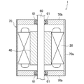
- FIG. 1 is a longitudinal sectional view schematically showing a configuration of a motor according to an embodiment of the present invention.
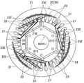
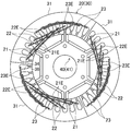
- FIG. 2 is a plan view showing the configuration of the motor of this embodiment.
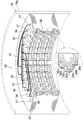
- FIG. 3 is a perspective view showing the configuration of the split stator core.
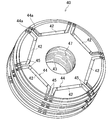
- FIG. 4 is a perspective view of the rotor.
- FIG. 5 is a side view of the rotor core.
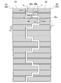
- FIG. 6 is an enlarged longitudinal sectional view showing a combined portion of the stator and the rotor.
- FIG. 7 is a plan view showing a configuration of a motor according to another embodiment.
- FIG. 1 is a longitudinal sectional view schematically showing a configuration of a motor (1) according to an embodiment of the present invention.
- the motor (1) includes a stator (20), a rotor (40), and a drive shaft (60), which are accommodated in a casing (70).
- the motor (1) is a so-called IPM (Interior Permanent Magnet) motor.
- the casing (70) has a cylindrical tube portion (70a) and an end plate (70b) that closes both ends of the tube portion (70a) and rotatably supports the drive shaft (60). is doing.
- the cylindrical portion (70a) is divided at intervals of 120 ° as in the stator core (30) described later.
- the drive shaft (60) is rotatably supported by the end plate (70b) via the bearing (61).
- the axial direction refers to the direction of the axis of the drive shaft (60), and the radial direction refers to the direction perpendicular to the axis.
- the outer peripheral side refers to the side far from the axis, and the inner peripheral side refers to the side closer to the axis.
- a lamination position means the position of the axial direction of the laminated board mentioned later.
- the stator (20) includes a stator core (30) and coil portions (21, 22, 23) formed by winding the coil in a substantially rectangular shape a plurality of times.
- the stator core (30) is configured as a laminated core in which a plurality of electromagnetic steel plates (laminated plates) are laminated in the axial direction.
- the stator core (30) includes a substantially cylindrical core back portion (35) and a plurality of teeth portions (34) projecting radially inward from the core back portion (35).
- the stator core (30) is composed of a plurality of members arranged in the circumferential direction.
- the stator core (30) is composed of three arc-shaped divided stator cores (31) divided at intervals of 120 °.
- the three split stator cores (31) are arranged so that the end faces of the split stator cores (31) adjacent in the circumferential direction are in contact with each other.
- segmented similarly is fixed to each outer peripheral surface of three division
- the present embodiment there are 36 teeth portions (34), and the same number of spaces are formed between the teeth portions (34).
- the space constitutes a coil slot (37) for accommodating the coil portion (21, 22, 23).
- twelve coil slots (37) are formed in one split stator core (31).
- each tooth tip portion (36) is a tooth tip (36) that is quadrilateral in plan view and wider in the circumferential direction than the base end (core back (35) side) body. It is configured. As shown in FIG. 3, each tooth tip portion (36) is configured such that the radially inner end surface thereof is uneven in the axial cross section.
- the uneven portion of each tooth tip portion (36) is referred to as a stator side uneven portion (38), and among the end surfaces on the radially inner side of the stator side uneven portion (38), the outermost surface is the bottom surface.
- the other surface is referred to as the top surface.
- the stator side uneven portion (38) has a first top surface (38a), a second top surface (38b), and a bottom surface (38c).
- the stator side uneven portion (38) changes the radial length (tooth tip length) of the laminated plate (33) forming the tooth tip portion (36) according to the lamination position of the laminated plate (33). Can be formed. Specifically, the inner end of the plurality of laminated plates (33) formed to the same radial length forming the first top surface (38a) (the portion on the inner peripheral side from the second top surface (38b)) ) Constitutes the first convex portion (38A). Further, the second end surface (the portion on the inner peripheral side from the bottom surface (38c)) of the plurality of laminated plates (33) formed to the same radial length forming the second top surface (38b) The convex part (38B) is comprised.
- each coil part (21, 22, 23) is configured such that the coil is wound around the plurality of tooth parts (34).
- the stator (20) includes a U-phase coil portion (21), a V-phase coil portion (22), and a W-phase coil portion (23).
- U-phase coil portions (21), V-phase coil portions (22), and W-phase coil portions (23) are provided for each of the divided stator cores (31). Two are provided.
- a rotating magnetic field can be generated in the stator (20) by supplying predetermined power to the coils of the coil portions (21, 22, 23).
- each coil part (21,22,23) has the coil end (21E, 22E, 23E) which protruded in the axial direction from the axial direction end surface of the stator core (30), respectively.
- the arrangement configuration of the coil ends (21E, 22E, 23E) of the coil portions (21, 22, 23) will be described later.
- the rotor (40) includes a rotor core (41) and a plurality of magnets (42).
- the rotor core (41) is a laminated core obtained by laminating a plurality of electromagnetic steel plates (laminated plate (43)) in the axial direction, and is formed in a cylindrical shape.
- a shaft hole (47) for inserting the drive shaft (60) is formed at the center of the rotor core (41).
- the rotor core (41) is formed with a plurality of magnet slots (44) for receiving the plurality of magnets (42), respectively.
- the magnet slots (44) are arranged at a 60 ° pitch around the axis of the shaft hole (47). That is, each magnet slot (44) is provided symmetrically with respect to the axis of the shaft hole (47).
- Each of the magnet slots (44) is formed in a substantially U shape in plan view (viewed in the axial direction of the shaft hole (47)) and penetrates the rotor core (41) in the axial direction.
- both end portions in the circumferential direction of each magnet slot (44) extend to the vicinity of the outer periphery of the rotor core (41).
- a portion that forms an end portion in the circumferential direction of the magnet slot (44) is referred to as a bridge portion (44a).
- the magnet (42) is held near the center of the magnet slot (44).
- the total length of the magnet (42) is shorter than the total length of the magnet slot (44), and the gaps (45) with the magnets (42) accommodated in the circumferential ends of each magnet slot (44) are provided. Are formed respectively.
- the rotor core (41) is configured such that the radially outer end face is uneven in the axial section.
- the uneven portion of the rotor core (41) is referred to as the rotor-side uneven portion (46)
- the innermost peripheral surface of the radially outer end surface of the rotor-side uneven portion (46) is the bottom surface, and the others. Is referred to as the top surface.
- the rotor-side uneven portion (46) has a first top surface (46 a), a second top surface (46 b), and a bottom surface (46 c).
- the rotor side uneven portion (46) can be formed by changing the diameter of the laminated plate (43) according to the laminated position of the laminated plate (43). Specifically, the first convex portion (the outer peripheral portion from the second top surface (46b)) of the plurality of laminated plates (43) having the same diameter forming the first top surface (46a) 46A) is configured. Further, the second convex portion (46B) is configured by the outer end portion (the portion on the outer peripheral side from the bottom surface (46c)) of the plurality of laminated plates (43) having the same diameter forming the second top surface (46b). Yes.
- FIG. 6 is a cross-sectional view of a state in which the stator (20) and the rotor (40) are combined. As shown in FIG. 6, when the stator (20) and the rotor (40) are combined, the stator core (30) and the rotor core (41) have a gap (G) that extends alternately and continuously in the radial direction and the axial direction. Are opposed to each other in the radial direction and the axial direction.
- the second top surface (46b) of the second convex portion (46B) of the portion (46), the second top surface (38b) of the second convex portion (38B) of the stator side uneven portion (38), the rotor side uneven portion ( 46) and the first top surface (38a) of the first convex portion (38A) of the stator side uneven portion (38) face each other, and a gap extending in the axial direction is formed therebetween. .
- the axial end surface of the first convex portion (46A) of the rotor side uneven portion (46), the axial end surface of the second convex portion (38B) of the stator side uneven portion (38), and the rotor side uneven portion are opposed to each other, and a gap extending in the radial direction therebetween. Is forming.
- stator side uneven portion (38) and the rotor side uneven portion (46) are alternately and continuously arranged between the stator core (30) and the rotor core (41) in the radial direction and the axial direction.
- An extending gap (solid gap) is formed.
- the size of the gap (G) is 0.3 mm in both the radial direction and the axial direction.
- the coil ends (21E, 22E, 23E) of the coil portions (21, 22, 23) are arranged as follows.
- the coil end (21E) of the U-phase coil portion (21) protrudes in the axial direction from the axial end portion of the stator core (30) and immediately tilts radially inward, and the other phase coil portions (22, 23 ) Of the coil ends (22E, 23E). As shown in FIG. 2, the coil end (21E) of the U-phase coil portion (21) passes through the inner side of the inner peripheral surface of the stator core (30).
- the coil end (22E) of the V-phase coil portion (22) protrudes in the axial direction from the axial end portion of the stator core (30).
- the coil end (22E) of the V-phase coil portion (22) is formed so as to connect the coil slot (37) that accommodates the V-phase coil portion (22) with the shortest path, and is straight in plan view. It is formed in a shape.
- the coil end (23E) of the W-phase coil portion (23) is curved in the circumferential direction of the stator core (30) without tilting after protruding axially from the axial end of the stator core (30). .
- each divided stator core (31) by welding or the like (see FIG. 3).
- each coil part (21,22,23) is attached to each division
- each coil part (21,22,23) is shape
- each coil part (21,22,23) is attached in order so that a several teeth part (34) may be straddled.
- the rotor (40) is fixed to the drive shaft (60). Then, the drive shaft (60) is attached to the end plate (70b) of the casing (70).
- each divided stator core (31) to which each coil part (21, 22, 23) is attached is assembled with the rotor (40). Specifically, each divided stator core (31) is moved radially inward from the outer peripheral side of the rotor (40) to the installation position, and the cylindrical portion (70a) of the casing (70) fixed to each divided stator core (31). ) Is fixed at a predetermined position of the end plate (70b). At this time, each of the divided stator cores (31) and the rotor (40) is formed between the stator core (30) and the rotor core (41) so that a gap (G) extending alternately and continuously in the radial direction and the axial direction is formed. And assemble. In this way, the motor (1) is assembled.
- the stator core (30) is configured by the three divided stator cores (31) arranged in the circumferential direction, and each of the coil portions (21, 22, 23) has the three divided stator cores (31). ) Are arranged so as not to straddle any two. Therefore, the stator (20) and the rotor (31) are assembled by moving the divided stator cores (31) to which the coil portions (21, 22, 23) are attached from the outer peripheral side of the rotor (40) toward the radially inner side. 40) can be assembled with. Therefore, even if one of the coil ends (21E, 22E, 23E) passes inside the inner peripheral surface of the stator core (30), the coil end ( 21E, 22E, 23E) can be prevented from coming into contact with the rotor (40).
- the coil end (21E) of at least one coil portion passes through the inner side of the inner peripheral surface of the stator core (30). Since it comprised so, the said coil end (21E) can be formed short compared with the case where it forms so that it may bulge to the outer peripheral side of a stator core (30). Therefore, according to the motor (1), the coil end (21E) is avoided while the coil end (21E, 22E, 23E) and the rotor (40) are prevented from contacting each other when the stator (20) and the rotor (40) are assembled. , 22E, 23E) can be shortened, and the electrical resistance at the coil ends (21E, 22E, 23E) can be reduced to suppress a reduction in efficiency due to copper loss.
- a plurality of coils arranged at the same angular position can be obtained by using an area inside the inner peripheral surface of the stator core (30) as an arrangement area of the coil ends (21E, 22E, 23E).
- the ends (21E, 22E, 23E) can be radially arranged without being stacked in the axial direction.
- the axial height of the coil end (21E, 22E, 23E) can be suppressed, and the coil end can be used by using a region inside the inner peripheral surface of the stator core (30) that could not be used conventionally. Since the expansion of (21E, 22E, 23E) to the outer peripheral side can be suppressed, the radial length of the stator core (30) can be reduced. Accordingly, it is possible to improve the efficiency of the motor (1) by reducing the size of the motor (1) and further shortening the coil ends (21E, 22E, 23E).
- At least one coil end (in this embodiment, the V-phase coil end (22E)) of the plurality of coil portions (21, 22, 23) is in the axial direction of the stator core (30). Both ends located on the end face are connected by the shortest path, and are formed in a straight line shape in plan view.
- the stator core ( 30) is constituted by three divided stator cores (31), so that the coil end (22E) can be prevented from coming into contact with the rotor (40) when the stator (20) and the rotor (40) are assembled. it can.
- the motor (1) there is a gap (G) in which the stator core (30) and the rotor core (41) are alternately and continuously extended in the radial direction and the axial direction between the cores (30, 41).
- G the stator core
- the rotor core (41) are alternately and continuously extended in the radial direction and the axial direction between the cores (30, 41).
- the efficiency can be improved without increasing the size of the motor (1).
- Embodiments may have the following configurations.
- each coil part (21, 22, 23) is not limited to that of the above embodiment.
- Each coil part (21, 22, 23) should just be arrange
- the coil end (21E) of the U-phase coil portion (21) is configured to pass inside the inner peripheral surface of the stator core (30), but the V-phase coil portion ( The coil end (22E) of 22) or the coil end (23E) of the W-phase coil portion (23) may pass through the inner peripheral surface of the stator core (30).
- each coil end (21E, 22E, 23E) can be shortened, so the electrical resistance at the coil end (21E, 22E, 23E) is reduced to suppress the decrease in efficiency due to copper loss. can do.
- the size of the gap (G) in the above embodiment is an example, and may be a different size. Further, the gap (G) may have a different size in the axial direction and the radial direction.
- grooved part (46) are two convex parts (a 1st convex part (38A, 46A) and a 2nd convex part (38B, 46B)), respectively.
- the shape of both the uneven portions (38, 46) is not limited to this.
- each of the stator side uneven portion (38) and the rotor side uneven portion (46) may have one convex portion, or may have three or more convex portions.
- the motor (1) was demonstrated as an example of the rotary electric machine which concerns on this invention, the rotary electric machine which concerns on this invention is the same stator (20) and rotor (40) as the said embodiment.
- the generator provided with may be sufficient.
- the present invention can also be applied to a reluctance rotary electric machine in which the rotor (40) does not include a magnet.
- the present invention is useful for a rotating electric machine such as a motor having a coil portion distributedly wound.
- Motor (rotary electric machine) 20 Stator 21, 22, 23 Coil portion 21E, 22E, 23E Coil end 30 Stator core 31 Split stator core (member) 38 Stator-side irregularities (irregularities) 40 rotor 41 Rotor core 46 Concave and convex portions on the rotor side (concave and convex portions) 60 Drive shaft G gap
Landscapes
- Engineering & Computer Science (AREA)
- Power Engineering (AREA)
- Manufacturing & Machinery (AREA)
- Iron Core Of Rotating Electric Machines (AREA)
- Insulation, Fastening Of Motor, Generator Windings (AREA)
- Manufacture Of Motors, Generators (AREA)
- Windings For Motors And Generators (AREA)
Abstract
Priority Applications (7)
| Application Number | Priority Date | Filing Date | Title |
|---|---|---|---|
| EP11762231.6A EP2555389B1 (fr) | 2010-03-31 | 2011-03-28 | Machine électrique tournante |
| BR112012022992A BR112012022992B1 (pt) | 2010-03-31 | 2011-03-28 | máquina elétrica rotativa |
| KR1020127027220A KR101438297B1 (ko) | 2010-03-31 | 2011-03-28 | 회전 전기 기계의 조립 방법 |
| US13/638,041 US20130026874A1 (en) | 2010-03-31 | 2011-03-28 | Rotary electric machine |
| CN2011800170083A CN102835004A (zh) | 2010-03-31 | 2011-03-28 | 回转电机 |
| AU2011233453A AU2011233453B9 (en) | 2010-03-31 | 2011-03-28 | Rotary electric machine |
| US14/603,771 US9438090B2 (en) | 2010-03-31 | 2015-01-23 | Method of assembling a rotary electric machine |
Applications Claiming Priority (2)
| Application Number | Priority Date | Filing Date | Title |
|---|---|---|---|
| JP2010080760A JP5617313B2 (ja) | 2010-03-31 | 2010-03-31 | 回転電気機械の組み立て方法 |
| JP2010-080760 | 2010-03-31 |
Related Child Applications (2)
| Application Number | Title | Priority Date | Filing Date |
|---|---|---|---|
| US13/638,041 A-371-Of-International US20130026874A1 (en) | 2010-03-31 | 2011-03-28 | Rotary electric machine |
| US14/603,771 Continuation US9438090B2 (en) | 2010-03-31 | 2015-01-23 | Method of assembling a rotary electric machine |
Publications (1)
| Publication Number | Publication Date |
|---|---|
| WO2011121983A1 true WO2011121983A1 (fr) | 2011-10-06 |
Family
ID=44711746
Family Applications (1)
| Application Number | Title | Priority Date | Filing Date |
|---|---|---|---|
| PCT/JP2011/001838 Ceased WO2011121983A1 (fr) | 2010-03-31 | 2011-03-28 | Machine électrique tournante |
Country Status (8)
| Country | Link |
|---|---|
| US (2) | US20130026874A1 (fr) |
| EP (1) | EP2555389B1 (fr) |
| JP (1) | JP5617313B2 (fr) |
| KR (1) | KR101438297B1 (fr) |
| CN (2) | CN104201831B (fr) |
| AU (1) | AU2011233453B9 (fr) |
| BR (1) | BR112012022992B1 (fr) |
| WO (1) | WO2011121983A1 (fr) |
Cited By (3)
| Publication number | Priority date | Publication date | Assignee | Title |
|---|---|---|---|---|
| CN103718435A (zh) * | 2011-08-08 | 2014-04-09 | 丰田自动车株式会社 | 旋转电机 |
| US20140125152A1 (en) * | 2012-11-08 | 2014-05-08 | Johnson Electric S.A. | Electromagnetic drive mechanism |
| JP2022137412A (ja) * | 2021-03-09 | 2022-09-22 | 三菱電機株式会社 | ステーター、ステーターの製造方法、交流回転電機の製造方法、誘導電動機および送風機 |
Families Citing this family (13)
| Publication number | Priority date | Publication date | Assignee | Title |
|---|---|---|---|---|
| DE102014103568A1 (de) | 2014-03-14 | 2015-09-17 | Xylem Ip Holdings Llc | Stator-Rotor-Vorrichtung für eine elektrische Maschine |
| JP6260696B2 (ja) | 2014-06-09 | 2018-01-17 | 日産自動車株式会社 | 平角線ステータコイルの製造方法 |
| DE102014111239B4 (de) * | 2014-08-07 | 2016-07-21 | Schuler Pressen Gmbh | Blechpaket eines Stators oder eines Läufers sowie eine elektrische Maschine |
| JP2016103869A (ja) * | 2014-11-27 | 2016-06-02 | 日本オイルポンプ株式会社 | 電動モータ |
| WO2017038706A1 (fr) * | 2015-08-28 | 2017-03-09 | アイシン・エィ・ダブリュ株式会社 | Bobine de stator, procédé de fabrication de stator, et machine électrique tournante |
| US20180198353A1 (en) * | 2015-08-28 | 2018-07-12 | Aisin Aw Co., Ltd | Method for manufacturing stator and method for manufacturing rotating electrical machine |
| JP6745202B2 (ja) * | 2016-11-25 | 2020-08-26 | 株式会社Soken | 回転電機 |
| DE102017119530A1 (de) * | 2017-08-25 | 2019-02-28 | Wobben Properties Gmbh | Generatorläufer und Generatorstator sowie Generator und Windenergieanlage damit und Verfahren zum Transportieren eines Generators |
| JP7449657B2 (ja) * | 2019-08-29 | 2024-03-14 | 株式会社小松製作所 | モータ |
| CN112751432A (zh) * | 2019-10-31 | 2021-05-04 | 罗伯特·博世有限公司 | 转子和电机 |
| JP7556703B2 (ja) * | 2020-06-10 | 2024-09-26 | 株式会社マキタ | 電動作業機セット及び電動作業機の製造方法 |
| CN112260420A (zh) * | 2020-10-26 | 2021-01-22 | 珠海格力节能环保制冷技术研究中心有限公司 | 定转子结构、电机、空调器 |
| CN120110112A (zh) * | 2025-03-13 | 2025-06-06 | 沈阳工业大学 | 一种混合气隙式双凸极电机 |
Citations (5)
| Publication number | Priority date | Publication date | Assignee | Title |
|---|---|---|---|---|
| JPH11289726A (ja) * | 1998-03-31 | 1999-10-19 | Nissan Motor Co Ltd | レラクタンスモータ |
| JP2005012974A (ja) | 2003-06-20 | 2005-01-13 | Toyota Motor Corp | ステータ、モータ、ステータの製造方法、ステータ鉄心の巻線装置、およびその使用方法 |
| JP2009189078A (ja) * | 2008-02-01 | 2009-08-20 | Toyota Industries Corp | 回転電機の固定子及び回転電機 |
| JP2009273216A (ja) * | 2008-05-06 | 2009-11-19 | Denso Corp | モータ |
| WO2010007950A1 (fr) * | 2008-07-14 | 2010-01-21 | アイシン・エィ・ダブリュ株式会社 | Stator et son procédé de fabrication |
Family Cites Families (9)
| Publication number | Priority date | Publication date | Assignee | Title |
|---|---|---|---|---|
| DE2460062A1 (de) * | 1974-12-19 | 1976-06-24 | Ernst Lerche | Elektrische maschine |
| JPS5942541B2 (ja) * | 1977-01-21 | 1984-10-16 | 芝浦メカトロニクス株式会社 | 細型電動機の固定子 |
| JPS61218355A (ja) * | 1985-03-22 | 1986-09-27 | Res Dev Corp Of Japan | 回転位置決め機能を有する磁気浮上アクチユエ−タ |
| JPS6146139A (ja) * | 1985-08-09 | 1986-03-06 | Shibaura Eng Works Co Ltd | 細型電動機の固定子 |
| US4968911A (en) * | 1985-11-20 | 1990-11-06 | Allied-Signal Inc. | Clam-shell stator construction for electrical machines |
| US5567999A (en) * | 1992-02-20 | 1996-10-22 | Dana Corporation | Bobbin structure for electromagnetic coil assembly |
| US5485046A (en) * | 1992-02-20 | 1996-01-16 | Dana Corporation | Variable reluctance electric motor |
| CN101079556A (zh) * | 2006-05-25 | 2007-11-28 | 哈尔滨理工大学 | 新型发电机定子结构 |
| WO2009025144A1 (fr) * | 2007-08-17 | 2009-02-26 | Kabushiki Kaisha Yaskawa Denki | Stator et machine électrique tournante l'utilisant |
-
2010
- 2010-03-31 JP JP2010080760A patent/JP5617313B2/ja active Active
-
2011
- 2011-03-28 CN CN201410457818.6A patent/CN104201831B/zh active Active
- 2011-03-28 WO PCT/JP2011/001838 patent/WO2011121983A1/fr not_active Ceased
- 2011-03-28 US US13/638,041 patent/US20130026874A1/en not_active Abandoned
- 2011-03-28 KR KR1020127027220A patent/KR101438297B1/ko not_active Expired - Fee Related
- 2011-03-28 CN CN2011800170083A patent/CN102835004A/zh active Pending
- 2011-03-28 EP EP11762231.6A patent/EP2555389B1/fr active Active
- 2011-03-28 BR BR112012022992A patent/BR112012022992B1/pt active IP Right Grant
- 2011-03-28 AU AU2011233453A patent/AU2011233453B9/en active Active
-
2015
- 2015-01-23 US US14/603,771 patent/US9438090B2/en active Active
Patent Citations (5)
| Publication number | Priority date | Publication date | Assignee | Title |
|---|---|---|---|---|
| JPH11289726A (ja) * | 1998-03-31 | 1999-10-19 | Nissan Motor Co Ltd | レラクタンスモータ |
| JP2005012974A (ja) | 2003-06-20 | 2005-01-13 | Toyota Motor Corp | ステータ、モータ、ステータの製造方法、ステータ鉄心の巻線装置、およびその使用方法 |
| JP2009189078A (ja) * | 2008-02-01 | 2009-08-20 | Toyota Industries Corp | 回転電機の固定子及び回転電機 |
| JP2009273216A (ja) * | 2008-05-06 | 2009-11-19 | Denso Corp | モータ |
| WO2010007950A1 (fr) * | 2008-07-14 | 2010-01-21 | アイシン・エィ・ダブリュ株式会社 | Stator et son procédé de fabrication |
Cited By (6)
| Publication number | Priority date | Publication date | Assignee | Title |
|---|---|---|---|---|
| CN103718435A (zh) * | 2011-08-08 | 2014-04-09 | 丰田自动车株式会社 | 旋转电机 |
| CN103718435B (zh) * | 2011-08-08 | 2016-02-17 | 丰田自动车株式会社 | 旋转电机 |
| US20140125152A1 (en) * | 2012-11-08 | 2014-05-08 | Johnson Electric S.A. | Electromagnetic drive mechanism |
| US9444291B2 (en) * | 2012-11-08 | 2016-09-13 | Johnson Electric S.A. | Electromagnetic drive mechanism |
| JP2022137412A (ja) * | 2021-03-09 | 2022-09-22 | 三菱電機株式会社 | ステーター、ステーターの製造方法、交流回転電機の製造方法、誘導電動機および送風機 |
| JP7630308B2 (ja) | 2021-03-09 | 2025-02-17 | 三菱電機株式会社 | ステーター、ステーターの製造方法、交流回転電機の製造方法、誘導電動機および送風機 |
Also Published As
| Publication number | Publication date |
|---|---|
| CN104201831B (zh) | 2017-03-15 |
| CN104201831A (zh) | 2014-12-10 |
| CN102835004A (zh) | 2012-12-19 |
| US9438090B2 (en) | 2016-09-06 |
| BR112012022992A2 (pt) | 2017-12-12 |
| AU2011233453A1 (en) | 2012-11-08 |
| US20130026874A1 (en) | 2013-01-31 |
| EP2555389B1 (fr) | 2019-02-20 |
| EP2555389A4 (fr) | 2017-05-03 |
| US20150135519A1 (en) | 2015-05-21 |
| JP2011217444A (ja) | 2011-10-27 |
| JP5617313B2 (ja) | 2014-11-05 |
| BR112012022992B1 (pt) | 2019-12-31 |
| AU2011233453B9 (en) | 2015-04-02 |
| AU2011233453B2 (en) | 2014-11-20 |
| KR101438297B1 (ko) | 2014-09-05 |
| KR20130008053A (ko) | 2013-01-21 |
| EP2555389A1 (fr) | 2013-02-06 |
Similar Documents
| Publication | Publication Date | Title |
|---|---|---|
| JP5617313B2 (ja) | 回転電気機械の組み立て方法 | |
| JP5958502B2 (ja) | 回転子およびそれを用いた回転電機 | |
| JP6461381B2 (ja) | 回転電機の固定子、回転電機、および、回転電機の固定子の製造方法 | |
| JP2014165938A (ja) | 回転電機 | |
| JP6044382B2 (ja) | マルチギャップ型回転電機 | |
| JP2010246343A (ja) | 電機における固定子 | |
| JP7449657B2 (ja) | モータ | |
| JP4286829B2 (ja) | 回転機の製造方法 | |
| JP5248048B2 (ja) | 回転電機の回転子及び回転電機 | |
| JP5593787B2 (ja) | 回転電気機械 | |
| JP7280070B2 (ja) | ステータ及びブラシレスモータ | |
| CN111630752A (zh) | 旋转电机的定子和旋转电机的定子的制造方法 | |
| JP5256835B2 (ja) | 回転電機の固定子及び回転電機 | |
| JP2013115836A (ja) | ブラシレスモータ及び電動ポンプ | |
| JP5487733B2 (ja) | スイッチング素子一体型回転電機 | |
| JP6302698B2 (ja) | 回転電機ユニット | |
| JP2011217454A (ja) | 回転電気機械 | |
| JP5401753B2 (ja) | 回転電機 | |
| JP7122831B2 (ja) | アウターロータ型回転電機 | |
| WO2024162233A1 (fr) | Moteur et procédé d'enroulement de bobine | |
| WO2022065345A1 (fr) | Stator et moteur | |
| JP2021058004A (ja) | モータ |
Legal Events
| Date | Code | Title | Description |
|---|---|---|---|
| WWE | Wipo information: entry into national phase |
Ref document number: 201180017008.3 Country of ref document: CN |
|
| 121 | Ep: the epo has been informed by wipo that ep was designated in this application |
Ref document number: 11762231 Country of ref document: EP Kind code of ref document: A1 |
|
| WWE | Wipo information: entry into national phase |
Ref document number: 13638041 Country of ref document: US |
|
| NENP | Non-entry into the national phase |
Ref country code: DE |
|
| WWE | Wipo information: entry into national phase |
Ref document number: 2999/KOLNP/2012 Country of ref document: IN |
|
| WWE | Wipo information: entry into national phase |
Ref document number: 2011762231 Country of ref document: EP |
|
| ENP | Entry into the national phase |
Ref document number: 20127027220 Country of ref document: KR Kind code of ref document: A |
|
| ENP | Entry into the national phase |
Ref document number: 2011233453 Country of ref document: AU Date of ref document: 20110328 Kind code of ref document: A |
|
| REG | Reference to national code |
Ref country code: BR Ref legal event code: B01A Ref document number: 112012022992 Country of ref document: BR |
|
| REG | Reference to national code |
Ref country code: BR Ref legal event code: B01E Ref document number: 112012022992 Country of ref document: BR |
|
| ENP | Entry into the national phase |
Ref document number: 112012022992 Country of ref document: BR Kind code of ref document: A2 Effective date: 20120912 |