WO2011122020A1 - X線照射装置および分析装置 - Google Patents
X線照射装置および分析装置 Download PDFInfo
- Publication number
- WO2011122020A1 WO2011122020A1 PCT/JP2011/001904 JP2011001904W WO2011122020A1 WO 2011122020 A1 WO2011122020 A1 WO 2011122020A1 JP 2011001904 W JP2011001904 W JP 2011001904W WO 2011122020 A1 WO2011122020 A1 WO 2011122020A1
- Authority
- WO
- WIPO (PCT)
- Prior art keywords
- ray
- rays
- irradiation apparatus
- ray irradiation
- sample
- Prior art date
- Legal status (The legal status is an assumption and is not a legal conclusion. Google has not performed a legal analysis and makes no representation as to the accuracy of the status listed.)
- Ceased
Links
Images






Classifications
-
- G—PHYSICS
- G01—MEASURING; TESTING
- G01N—INVESTIGATING OR ANALYSING MATERIALS BY DETERMINING THEIR CHEMICAL OR PHYSICAL PROPERTIES
- G01N23/00—Investigating or analysing materials by the use of wave or particle radiation, e.g. X-rays or neutrons, not covered by groups G01N3/00 – G01N17/00, G01N21/00 or G01N22/00
- G01N23/22—Investigating or analysing materials by the use of wave or particle radiation, e.g. X-rays or neutrons, not covered by groups G01N3/00 – G01N17/00, G01N21/00 or G01N22/00 by measuring secondary emission from the material
- G01N23/227—Measuring photoelectric effect, e.g. photoelectron emission microscopy [PEEM]
- G01N23/2273—Measuring photoelectron spectrum, e.g. electron spectroscopy for chemical analysis [ESCA] or X-ray photoelectron spectroscopy [XPS]
-
- G—PHYSICS
- G21—NUCLEAR PHYSICS; NUCLEAR ENGINEERING
- G21K—HANDLING OF PARTICLES OR IONISING RADIATION NOT OTHERWISE PROVIDED FOR; IRRADIATION DEVICES; GAMMA RAY OR X-RAY MICROSCOPES
- G21K1/00—Arrangements for handling particles or ionising radiation, e.g. focusing or moderating
- G21K1/06—Arrangements for handling particles or ionising radiation, e.g. focusing or moderating using diffraction, refraction or reflection, e.g. monochromators
-
- G—PHYSICS
- G21—NUCLEAR PHYSICS; NUCLEAR ENGINEERING
- G21K—HANDLING OF PARTICLES OR IONISING RADIATION NOT OTHERWISE PROVIDED FOR; IRRADIATION DEVICES; GAMMA RAY OR X-RAY MICROSCOPES
- G21K7/00—Gamma- or X-ray microscopes
-
- H—ELECTRICITY
- H01—ELECTRIC ELEMENTS
- H01J—ELECTRIC DISCHARGE TUBES OR DISCHARGE LAMPS
- H01J35/00—X-ray tubes
- H01J35/24—Tubes wherein the point of impact of the cathode ray on the anode or anticathode is movable relative to the surface thereof
- H01J35/28—Tubes wherein the point of impact of the cathode ray on the anode or anticathode is movable relative to the surface thereof by vibration, oscillation, reciprocation, or swash-plate motion of the anode or anticathode
-
- H—ELECTRICITY
- H01—ELECTRIC ELEMENTS
- H01J—ELECTRIC DISCHARGE TUBES OR DISCHARGE LAMPS
- H01J35/00—X-ray tubes
- H01J35/24—Tubes wherein the point of impact of the cathode ray on the anode or anticathode is movable relative to the surface thereof
- H01J35/30—Tubes wherein the point of impact of the cathode ray on the anode or anticathode is movable relative to the surface thereof by deflection of the cathode ray
-
- G—PHYSICS
- G01—MEASURING; TESTING
- G01N—INVESTIGATING OR ANALYSING MATERIALS BY DETERMINING THEIR CHEMICAL OR PHYSICAL PROPERTIES
- G01N2223/00—Investigating materials by wave or particle radiation
- G01N2223/20—Sources of radiation
- G01N2223/204—Sources of radiation source created from radiated target
-
- G—PHYSICS
- G01—MEASURING; TESTING
- G01N—INVESTIGATING OR ANALYSING MATERIALS BY DETERMINING THEIR CHEMICAL OR PHYSICAL PROPERTIES
- G01N2223/00—Investigating materials by wave or particle radiation
- G01N2223/20—Sources of radiation
- G01N2223/206—Sources of radiation sources operating at different energy levels
-
- H—ELECTRICITY
- H01—ELECTRIC ELEMENTS
- H01J—ELECTRIC DISCHARGE TUBES OR DISCHARGE LAMPS
- H01J2235/00—X-ray tubes
- H01J2235/08—Targets (anodes) and X-ray converters
- H01J2235/081—Target material
-
- H—ELECTRICITY
- H01—ELECTRIC ELEMENTS
- H01J—ELECTRIC DISCHARGE TUBES OR DISCHARGE LAMPS
- H01J2235/00—X-ray tubes
- H01J2235/08—Targets (anodes) and X-ray converters
- H01J2235/086—Target geometry
-
- H—ELECTRICITY
- H01—ELECTRIC ELEMENTS
- H01J—ELECTRIC DISCHARGE TUBES OR DISCHARGE LAMPS
- H01J2235/00—X-ray tubes
- H01J2235/16—Vessels
- H01J2235/163—Vessels shaped for a particular application
Definitions
- the present invention relates to an X-ray irradiation apparatus that collects X-rays emitted from an X-ray generation mechanism at a predetermined focal position by a condensing mechanism, and an analysis apparatus including the X-ray irradiation apparatus.
- X-ray photoelectron spectroscopy is known as one of surface analysis methods. XPS can obtain information on elements and chemical bonding states present in a sample by analyzing the kinetic energy of photoelectrons emitted from the sample surface by X-ray irradiation.
- XPS X-ray photoelectron spectroscopy
- Patent Document 1 and Non-Patent Document 1 an electron gun for generating a focused electron beam, an anode that generates X-rays when a focused electron beam is incident, and an X generated by the anode
- An electron spectroscopic device which comprises a focusing means for focusing the line on the sample surface and an analyzer means for analyzing the photoelectron energy emitted from the sample surface upon irradiation with X-rays.
- Patent Document 2 and Non-Patent Document 2 describe an X-ray spectrometer and an X-ray analyzer provided with spectroscopic means capable of selecting a plurality of X-rays having different energies by one apparatus. It was considered impossible to focus X-rays on the sample surface with a wide range of energy adjustments by one device.
- an object of the present invention is to provide an X-ray irradiation apparatus capable of adjusting a wide range of X-ray energy and an analysis apparatus using the X-ray irradiation apparatus.
- the X-ray irradiation apparatus is an X-ray irradiation apparatus that condenses X-rays emitted from the X-ray generation mechanism at a predetermined focal position by the condensing mechanism, and the X-ray generation mechanism has different wavelengths.
- a second aspect of the present invention is the X-ray irradiation apparatus according to the first aspect, wherein the light collector has a mirror surface with a radius of curvature equal to the diameter of a Roland circle having the X-ray generation position that matches the diffraction characteristics and the focal position as a passing point. Is an X-ray reflecting mirror disposed on the Roland circle.
- a third aspect of the present invention is the X-ray irradiation apparatus according to the second aspect, wherein the X-ray reflecting mirror is installed for each wavelength of the generated X-ray, and each X-ray reflecting mirror has an optical path of an X-ray having a wavelength not corresponding to its own diffraction characteristics. The use position is set at a position deviating from the above.
- a fourth aspect of the present invention is the X-ray irradiation apparatus according to the second aspect, wherein the X-ray reflecting mirror is installed for each wavelength of the generated X-ray, and is used at a position overlapping with an X-ray optical path having a wavelength not corresponding to its own diffraction characteristics.
- the X-ray reflecting mirror to which is set is provided with a retracting structure that retracts to a position off the optical path when not in use.
- a fifth aspect of the present invention is the X-ray irradiation apparatus according to any one of the first to fourth aspects, wherein the X-ray generation mechanism generates an electron gun that emits a constant electron beam and X-rays having different wavelengths by irradiation with the electron beam. It comprises a plurality of X-ray sources and a wavelength selection structure for selecting an X-ray source irradiated with the electron beam and selecting a wavelength of the generated X-rays.
- the analyzer according to a sixth aspect of the present invention is an analyzer characterized in that the X-ray irradiation apparatus is the X-ray irradiation apparatus according to any one of the first to fifth aspects, and the focal position is set as a sample installation position.
- a seventh aspect of the present invention is the analyzer according to the sixth aspect, wherein the analyzer is based on detection of kinetic energy of photoelectrons emitted from the sample.
- Inventions 1 and 2 have a close relationship between the energy of X-rays and the wavelength thereof, and in order to give the energy to a sample with high efficiency, a light collector having diffraction characteristics adapted to the wavelength of X-rays Based on the knowledge that it can be achieved by using X-rays, not only the X-ray generation mechanism that generates multiple types of X-rays with different wavelengths, but also the light collection mechanism has diffraction characteristics suitable for each X-ray wavelength. Is. As a result, the X-ray is irradiated at the focal position without the energy being attenuated.
- inventions 3 and 4 relate to securing an optical path space generated when X-rays having different wavelengths are used.
- the condensing mechanism becomes a large one spreading in the horizontal direction by the number of different X-rays, but the operation as in the invention 4 is not necessary.
- invention 4 although it can be set as the compact condensing mechanism which hardly spreads in a horizontal direction, when changing a wavelength, operation which moves a condensing body is needed. However, since this operation can be performed together with the wavelength change by automatic control, the troublesomeness in operation can be substantially eliminated.
- Invention 5 shows a specific example for changing the wavelength of X-rays.
- a plurality of X-ray sources that generate X-rays having a specific wavelength by excitation with an electron beam are used, and the wavelength of the X-rays can be set by the X-ray source that irradiates the electron beam.
- the wavelength of the X-ray can be dynamically changed, and can be widely applied to the difference in the material of the sample and the difference in the purpose of analysis.
- Inventions 6 and 7 are analysis apparatuses that effectively utilize the effects of the X-ray irradiation apparatus of the present invention, and not only have the advantages of the above-mentioned X-ray irradiation apparatuses, but also the analysis results on both the surface and the depth. It can be obtained in association with each other, and a three-dimensional X-ray analysis result can be obtained.
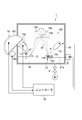
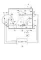
- FIG. 1 is a schematic configuration diagram of an analyzer according to Example 1.
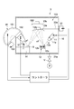
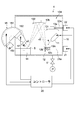
- FIG. It is a schematic block diagram of the said apparatus which shows one operation example of the analyzer of FIG.
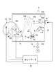
- FIG. It is a schematic block diagram of the said apparatus which shows the other operation example of the analyzer of FIG.
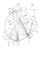
- It is a schematic perspective view of the X-ray irradiation apparatus used with the analyzer of FIG.
- FIG. 6 is a schematic configuration diagram of an analyzer according to Example 2.
- FIG. 6 is a schematic configuration diagram of an analyzer according to a third embodiment.
- FIG. 6 is a schematic configuration diagram of an analyzer according to a fourth embodiment. It is a schematic block diagram of the said apparatus which shows the operation example of the analyzer of FIG. It is a schematic perspective view which shows the X-ray irradiation apparatus which concerns on other embodiment of this invention. It is a schematic block diagram of the analyzer which concerns on other embodiment of this invention.
- the X-ray irradiation apparatus of the present invention is an X-ray irradiation apparatus that condenses the X-rays emitted from the X-ray generation mechanism at a predetermined focal position by the condensing mechanism, and the X-ray generation mechanism has different wavelengths.
- a mirror surface having a radius of curvature equal to the diameter of the Roland circle having the X-ray generation position matching the diffraction characteristics and the focal position as the passing point is arranged on the Roland circle as the light collector.
- the present invention is not limited to this, and any X-ray reflecting mirror may be used as long as it has diffraction characteristics that match the wavelength of X-rays generated by the X-ray generation mechanism. Note that the suitability of diffraction characteristics means that X-rays can be monochromatized and a continuous spectrum portion of X-rays is removed, thereby realizing high-precision analysis with high energy resolution.
- some of the concentrators have diffraction characteristics that match X-rays of a plurality of wavelengths even if they are similar, so the X-ray wavelength to be generated and the number of concentrators are the same.
- Examples of the X-ray generation mechanism include an electron gun that emits a constant electron beam, a plurality of X-ray sources that generate X-rays having different wavelengths by irradiation of the electron beam, and an X-ray that is irradiated by the electron beam.
- An example is shown that includes a wavelength selection structure that selects a source and selects the wavelength of the generated X-ray.
- the X-ray sources shown in Table 1 are generally known. In this embodiment, it is assumed that a plurality of X-ray sources shown in Table 1 are selected and used.
- an X-ray source that generates X-rays having different wavelengths depending on the irradiation voltage of the electron beam may be used.
- the anode material of the X-ray source may be not only a plurality of pure material anodes but also a single alloy anode, for example, a CuAl alloy such as 80 at% Al / 20 at%.
- a CuAl alloy such as 80 at% Al / 20 at%.
- the CuK ⁇ ray can be selected by using a light collector having diffraction characteristics suitable for the CuK ⁇ ray.
- the energy of the AlK ⁇ ray and CuK ⁇ ray is about 1.49 keV and 8.05 keV, respectively. It does not occur. Therefore, generation of AlK ⁇ rays or CuK ⁇ rays and AlK ⁇ rays can be selected using an electron beam irradiation voltage of 9 kV as a threshold value.
- the electron beam irradiation voltage is preferably 5 times or more the energy of X-rays generated from each anode material.
- Non-Patent Document 3 the relationship between the spectral crystal (type, crystal face index and lattice constant) having diffraction characteristics adapted to the wavelength of various characteristic X-rays and the diffraction angle (2 ⁇ ) is described in Non-Patent Document 3 and well known. Yes, this known knowledge can also be used in the present invention.
- the analysis apparatus is exemplified by detecting the kinetic energy of photoelectrons emitted from the sample by irradiation of the X-ray sample.
- XRF fluorescent X-ray analyzer
- PEEM photoelectron microscope
- FIG. 1 is a schematic configuration diagram illustrating an analyzer according to the present embodiment.
- an X-ray photoelectron spectrometer XPS apparatus
- 2 and 3 are schematic views similar to FIG. 1 showing an example of the operation of the analyzer.
- the analysis apparatus 1 of the present embodiment includes a chamber 10, an X-ray irradiation apparatus 101, a stage 14, an analyzer 15, and a controller 20.
- the chamber 10 is connected to a vacuum pump P through a vacuum valve V, and the inside can be evacuated and maintained at a predetermined pressure (for example, 10 ⁇ 7 Pa level).
- the X-ray irradiation apparatus 101 includes an electron gun 11, an anode 12, a first light collector 13a, and a second light collector 13b.
- the electron gun 11 is installed inside the chamber 10 and irradiates the anode 12 with an electron beam (e).
- the electron gun 11 includes an electron source that generates electrons, and an electron lens that can focus the generated electrons and adjust the electron beam to a predetermined beam diameter.
- the electron source may be a hot cathode or a cold cathode.
- the electron lens may be an electric field type or a magnetic field type.
- the electron gun 11 has a deflector capable of deflecting an electron beam. The operation of generating, focusing and deflecting the electron beam by the electron gun 11 is controlled by the controller 20.
- the anode 12 includes a first anode body 12a, a second anode body 12b, and a support body 12c that supports the first and second anode bodies 12a and 12b.
- the first and second anode bodies 12a and 12b are made of different metal materials, and generate X-rays (characteristic X-rays) each having a specific wavelength when irradiated with an electron beam. Function as.
- the support 12c is made of a metal material having excellent thermal conductivity, such as silver (Ag) or copper (Cu), and a cooling water passage through which cooling water circulates is formed.
- Al is used as the first anode body 12a
- Cr is used as the second anode body 12b.
- the first anode body 12a generates an AlK ⁇ ray (wavelength: 8.34 ⁇ , energy: 1.49 keV) as the first X-ray (x1) by being irradiated with an electron beam from the electron gun 11.
- the second anode body 12b is irradiated with an electron beam from the electron gun 11 to generate CrK ⁇ rays (wavelength: 2.29 ⁇ , energy: 5.41 keV) as second X-rays (x2).
- the electron gun 11 has a state in which the first anode body 12a is irradiated with an electron beam (first state) and a state in which the second anode body 12b is irradiated with an electron beam (second state).
- the irradiation condition of the electron beam is controlled independently in each state.
- the support 12c is configured such that the relative position with respect to the electron gun 11 is variable by the first moving mechanism 21.
- the first moving mechanism 21 is installed on the outer surface of the chamber 10 and has a drive rod 21a that penetrates the chamber 10 through a vacuum seal (not shown).
- the drive rod 21a is connected to the support 12c.
- the first moving mechanism 21 includes a cylinder device, a ball screw unit, a servo motor, and the like, and moves the support 12c in the horizontal direction by expanding and contracting the drive rod 21a.
- the operation of the first moving mechanism 21 is controlled by the controller 20.
- the irradiation range of the electron beam by the electron gun 11 is fixed to a certain range, and the first anode body 12a or the second anode body 12b is located in the irradiation range of the electron beam.
- the support 12c is moved. That is, as shown in FIG. 2, the first moving mechanism 21 moves the support 12c to the position (first position) where the first anode body 12a receives the electron beam when the first X-ray is generated. Move. Further, as shown in FIG. 3, the first moving mechanism 21 moves the support 12c to a position (second position) where the second anode body 12b is irradiated with an electron beam when the second X-ray is generated. Move.
- the support 12c is moved along a base installed inside the chamber 10.
- the 1st moving mechanism 21 is not restricted to the structure which moves the support body 12c by the expansion-contraction operation
- the support 12c may be configured to be movable by a gear mechanism installed inside the base.
- the electron gun 11, the anode 12, and the moving mechanism 21 constitute an “X-ray generation mechanism” according to the present invention.
- the first and second light collectors 13a and 13b constitute a “light condensing mechanism” according to the present invention, and are disposed inside the chamber 10, respectively.
- the first light collector 13 a is for condensing the first X-rays (AlK ⁇ rays) generated by the first anode body 12 a on the surface of the sample S on the stage 14.
- the second light collector 13b is for condensing second X-rays (CrK ⁇ rays) generated by the second anode body 12b on the surface of the sample S on the stage.
- the first light collector 13a has a first mirror surface 131 on which the first X-ray (AlK ⁇ ) is incident, and the second light collector 13b is a first mirror on which the second X-ray (CrK ⁇ ) is incident.
- Two mirror surfaces 132 are provided. These mirror surfaces 131 and 132 reflect the X-rays emitted from the anode bodies 12a and 12b toward the sample S, thereby forming a concave reflecting mirror that collects the X-rays in a minute region on the surface of the sample S. Thereby, the surface analysis of the fine area
- the X-ray spot diameter on the sample S depends on the beam diameter of the electron beam emitted from the electron gun 11, the accuracy of the spectroscopic crystal constituting the condenser, and the diameter is, for example, 5 ⁇ m to 200 ⁇ m.
- each of the light collectors 13a and 13b is composed of a spectral crystal (monochromator) that makes incident X-rays monochromatic.
- the spectral crystal has a function of selectively reflecting only X-rays having a predetermined wavelength satisfying the Bragg reflection condition.
- each of the light collectors 13a and 13b removes a continuous spectrum portion from incident X-rays and selectively reflects only desired characteristic X-rays (AlK ⁇ rays and CrK ⁇ rays).
- the analyzer 15 can realize a highly accurate surface analysis with high energy resolution.
- a material having a lattice constant corresponding to a target X-ray wavelength is used as the spectral crystal constituting the light collectors 13a and 13b.
- quartz is used for the first light collector 13a that condenses the first X-rays (AlK ⁇ rays).
- a Ge (germanium) crystal is used for the second light collector 13b that condenses the second X-ray (CrK ⁇ ray).
- the anode bodies 12a and 12b and the X-rays excited from them can be appropriately selected within the range described in Table 1 or beyond the range described in Table 1.
- the light collectors 13a and 13b can be appropriately selected according to the wavelength of the selected X-ray.
- the light collectors 13a and 13b are not limited to the case where the light collectors 13a and 13b are formed of the above-described spectral crystals, but may be formed of a diffraction grating or an optical multilayer film.
- the first and second light collectors 13a and 13b are arranged in the vacuum chamber 10 so as to have a common focal position. Thereby, X-rays having different wavelengths can be irradiated to the same location on the sample S.
- the mirror surfaces 131 and 132 of the respective light collectors are arranged on a plurality of different Roland circumferences passing through the anode 12 and the focal position, respectively.
- FIG. 4 is a schematic perspective view of the X-ray irradiation apparatus 101 for explaining the relative positional relationship between the anode 12, the sample S (stage 14), and the first and second light collectors 13a and 13b.
- the first light collector 13 a has a Roland circle (first Roland circle) whose passing point is an X-ray generation position suitable for the diffraction characteristics and a focal position on the sample S.
- a mirror surface 131 having a curvature equal to twice the diameter of C1 is provided, and the mirror surface 131 is arranged on the first Roland circle C1.
- the second light collector 13b has a diameter equal to the diameter of a Roland circle (second Roland circle) C2 whose passing point is the X-ray generation position suitable for the diffraction characteristics and the focal position on the sample S.
- the mirror surface 132 has a radius of curvature, and the mirror surface 132 is disposed on the second Roland circle C2.
- the X-rays of the respective wavelengths can be efficiently collected at the focal position.
- each of the light condensing surfaces 131 and 132 is formed in a spheroid shape, X-ray aberration at the focal position can be reduced. Although the aberration is larger than the spheroid shape, the mirror surfaces 131 and 132 of the light collectors 13a and 13b may have a toroidal shape.
- the first and second light collectors 13a and 13b are respectively located at positions where the X-rays emitted from the anode bodies 12a and 12b are incident on the mirror surfaces 131 and 132 of the light collectors at an incident angle close to perpendicular.
- a solid angle or etendue can be increased, and the flux of X-rays condensed at the focal position on the sample S can be increased.
- the stage 14 is configured as a support base that supports the sample S with its surface facing upward.
- the stage 14 may include a transport mechanism for transporting the sample S between the inside and the outside of the chamber 10, a ground mechanism for maintaining the sample S at the ground potential, and the like.
- the analyzer 15 separates photoelectrons (p) emitted from the surface of the sample S on the stage 14 by being irradiated with X-rays (AlK ⁇ rays, CrK ⁇ rays).
- the analyzer 15 includes an analyzer main body 151 that separates the kinetic energy of photoelectrons, an input lens 152 that guides the photoelectrons to the analyzer main body 151, and a detector 153 that detects the photoelectrons dispersed in the analyzer main body 151.
- the analyzer main body 151 has a plurality of electrodes for electrostatically separating photoelectrons, and the voltage applied between these electrodes is controlled by the controller 20.
- the input lens 152 has a multi-stage electrode unit, and the voltage applied to these electrodes is also controlled by the controller 20.
- the detector 153 includes, for example, an electron multiplier, and its output is supplied to the controller 20.
- the controller 20 is configured by a computer, for example, and controls the operations of the electron gun 11, the first moving mechanism 21, and the analyzer 15.
- the controller 20 performs the surface analysis of the sample S based on a predetermined algorithm, and displays the analysis result on a display (not shown) or stores it in a predetermined storage unit.
- the analyzer 1 of the present embodiment has an electron irradiation source 17 for neutralizing the surface of the sample S.
- the surface of the sample S is made of an insulating material, the surface may be positively charged by the emission of photoelectrons.
- the electron irradiation source 17 irradiates the sample S with low-speed electrons. The operation of the electron irradiation source 17 is controlled by the controller 20.
- the analyzer 1 of the present embodiment is configured as described above. Next, the operation of the analyzer 1 will be described.
- the surface analysis using the first X-ray (AlK ⁇ ray) and the surface analysis using the second X-ray (CrK ⁇ ray) are performed independently.
- FIG. 2 shows a state of the surface analysis of the sample S using the first X-ray.
- the controller 20 controls the first moving mechanism 21 to move the support 12c to a position (first position) where the first anode (Al anode) 12a receives the electron beam irradiation.
- the electron gun 11 irradiates the first anode body 12a with an electron beam (e), thereby generating first X-rays (x1: AlK ⁇ line) from the first anode body 12a.
- the first X-ray enters the first light collector 13a and is reflected by the mirror surface 131 toward the surface of the sample S on the stage. Since the first light collector 13a has the concave shape described above and is formed of a predetermined spectral crystal, the first X-ray reflected by the light collector 13a is monochromatized and becomes the color of the sample S. Focused on the surface.
- the sample S When the sample X is irradiated with the first X-ray, the sample S emits photoelectrons (p1) excited by the energy of the first X-ray.
- the emitted photoelectrons are guided to the analyzer main body 151 through the input lens 152, and after being separated, are detected by the detector 153.
- the controller 20 acquires the energy distribution of the photoelectron intensity by sweeping (sweeping) the input voltage to the analyzer main body 151 and the input lens 152 within a predetermined range.
- FIG. 3 shows a state of surface analysis of the sample S using the second X-ray.
- the controller 20 controls the first moving mechanism 21 to move the support 12c to a position (second position) where the second anode (Cr anode) 12b is irradiated with the electron beam.
- the electron gun 11 irradiates the second anode body 12b with an electron beam (e) to generate second X-rays (x2: CrK ⁇ rays) from the second anode body 12b.
- the second X-ray enters the second light collector 13 b and is reflected by the mirror surface 132 toward the surface of the sample S on the stage 14. Since the second condensing body 13b has the concave shape described above and is formed of a predetermined spectral crystal, the second X-ray reflected by the condensing body 13b is monochromatized and becomes the color of the sample S. Focused on the surface.
- the sample S emits photoelectrons (p2) excited by the energy of the second X-ray when irradiated with the second X-ray.
- the emitted photoelectrons are guided to the analyzer main body 151 through the input lens 152, and after being separated, are detected by the detector 153.
- the controller 20 acquires the energy distribution of the photoelectron intensity by sweeping (sweeping) the input voltage to the analyzer main body 151 and the input lens 152 within a predetermined range.
- the surface analysis is performed using the first and second X-rays having different wavelengths at the same position of the sample S. Since the X-rays of the respective wavelengths have different energies, the kinetic energy of photoelectrons emitted from the surface of the sample S differs depending on the type of X-rays. Therefore, for example, the first X-ray is obtained by taking the difference between the energy distribution of the photoelectron intensity acquired using the first X-ray and the energy distribution of the photoelectron intensity acquired using the second X-ray. In this case, it becomes possible to acquire depth information that cannot be acquired.
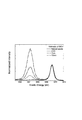
- FIG. 5 shows a spectroscopic spectrum of photoelectrons obtained by irradiating a Si substrate with a SiO 2 film having a thickness of 25 nm on the surface with CrK ⁇ rays.
- a peak derived from SiO 2 is observed near 3564.5 eV, and a peak derived from the Si substrate is observed near 3569 eV.
- illustration is omitted, when AlK ⁇ is used as the radiation source, a peak derived from the underlying Si substrate could not be recognized.
- FIG. 6 and 7 show an analyzer according to the present embodiment.
- portions corresponding to those in the first embodiment are given the same reference numerals, and detailed descriptions thereof are omitted.
- the first moving mechanism 21 moves the anode 12 relative to the electron gun 11 to irradiate the first anode body 12a with the electron beam (e), and the electron beam ( e) switched the state in which the second anode body 12b was irradiated.
- the position of the anode 12 is fixed, and the irradiation direction of the electron beam (e) is switched by the electron gun 11 to select the first X-ray (x1) and the second X-ray (x2).
- An X-ray irradiation apparatus 102 having an X-ray generation mechanism that can be generated automatically is provided.
- the electron gun 11 has a deflector 11a.
- the deflector 11a is controlled by the controller 20 to irradiate the first anode body 12a with the electron beam (e) as shown in FIG. 6, and to the second anode body 12b as shown in FIG. e) is selectively switched to the irradiation state.
- the controller 20 constitutes a “wavelength selection structure” according to the present invention for selecting the wavelength of the generated X-ray.
- the first and second light collectors 13a and 13b are arranged at predetermined fixed positions.
- the geometry of the anode bodies 12a, 12b, the sample S, and the light collectors 13a, 13b as described above can be obtained without the interference of the X-rays collected by the light collectors 13a, 13b.
- the analyzer 3 includes the second moving mechanism 22 for changing the relative position between the first light collector 13a and the second light collector 13b.
- the first light collector 13a is disposed closer to the anode 12 than the second light collector 13b. Therefore, in this embodiment, the relative position between the two light collectors 13a and 13b is changed by moving the first light collector 13a relative to the second light collector 13b.
- the second moving mechanism 22 constitutes a “retraction structure” according to the present invention.
- the light collectors 13a and 13b and the second moving mechanism 22 constitute a “light collecting mechanism” according to the present invention, and the light collecting mechanism, the electron gun 11 and the anode 12 are used in this embodiment.
- the X-ray irradiation apparatus 103 concerning is comprised.
- the second moving mechanism 22 is installed on the outer surface of the chamber 10 and has a drive rod 22a that penetrates the chamber 10 through a vacuum seal (not shown).
- the drive rod 22a is connected to the first light collector 13a.
- the second moving mechanism 22 includes a cylinder device, a ball screw unit, a servo motor, and the like, and moves the first light collector 13a in the horizontal direction by extending and contracting the drive rod 22a.
- the operation of the second moving mechanism 22 is controlled by the controller 20.
- the second moving mechanism 22 places the first light collector 13a on the first Roland circle C1 (FIG. 4) when the first X-ray is generated.
- the second moving mechanism 22 performs the second operation by the second light collector 13 b disposed on the second Roland circle C ⁇ b> 2 (FIG. 4).
- the first light collector 13a is horizontally moved to a position that does not hinder the X-ray condensing action.
- the first light collector 13a is moved along a guide portion (not shown) installed inside the chamber 10.
- the 2nd moving mechanism 22 is not restricted to the structure which moves the 1st condensing body 13a by the expansion-contraction operation
- both the first light collector 13a and the second light collector 13b are configured to be movable, and when the first X-ray is generated, the first light collector 13a. May be arranged on the first Roland circle C1, and when the second X-ray is generated, the second light collector 13b may be arranged on the second Roland circle C2.
- the chamber 10 can be reduced in size and each component in the chamber 10 can be reduced.
- the degree of freedom of the layout can be increased.
- the X-ray irradiation apparatus 103 of the present embodiment has the deflector 11a capable of deflecting the electron beam in the electron gun 11, the focal position due to the movement error of the first light collector 13a. Can be eliminated by changing the irradiation position of the electron beam on the anode body 12a.
- the analyzer 4 relates to a combination of the above-described first and third embodiments, and the first moving mechanism 21 that can move the anode 12 relative to the electron gun 11. And an X-ray irradiation device 104 having a second moving mechanism 22 capable of changing the relative position between the first and second light collectors 13a and 13b.
- FIG. 10 shows a state of the surface analysis of the sample S using the first X-ray.
- the controller 20 controls the first moving mechanism 21 to move the support 12c to a position (first position) where the first anode (Al anode) 12a receives the electron beam irradiation. Further, the controller 20 controls the second moving mechanism 22 to place the first light collector 13a (mirror surface 131) on the first Roland circle C1 (FIG. 4). Thereby, the surface analysis of the sample S using the first X-ray is performed.
- FIG. 11 shows a state of surface analysis of the sample S using the second X-ray.
- the controller 20 controls the first moving mechanism 21 to move the support 12c to a position (second position) where the second anode (Cr anode) 12b is irradiated with the electron beam.
- the controller 20 controls the second moving mechanism 22 so that the second X-ray is condensed by the second condenser 13b disposed on the second Roland circle C2 (FIG. 4).
- the first light collector 13a is horizontally moved to a position that does not impede. Thereby, the surface analysis of the sample S using the second X-ray is performed.
- the AlK ⁇ ray is used as the first X-ray and the CrK ⁇ ray is used as the second X-ray.
- the type of sample, etc. can be appropriately changed.
- FIG. 12 shows a schematic configuration of an X-ray irradiation apparatus 105 provided with a condensing mechanism having three condensing bodies 13a, 13b, and 13c.
- the first light collector 13a is disposed on a first Roland circle C1 that passes through the anode 12 and the sample S.
- the second light collector 13b is disposed on a second Roland circle C2 that passes through the anode 12 and the sample S.
- the third light collector 13c is disposed on a third Roland circle C3 that passes through the anode 12 and the sample S.
- FIG. 13 shows a schematic configuration of a fluorescent X-ray analyzer.
- the illustrated X-ray fluorescence analyzer 6 includes an X-ray irradiation device 101 and a photodetector 51.
- the photodetector 51 measures characteristic X-rays (fluorescent X-rays) (xf) generated from the sample S by being irradiated with X-rays having different wavelengths.
- the present invention can be applied to a photoelectron microscope using a photoelectron microscope instead of the photodetector 51.
- Electron gun 11a Deflector 12 ... Anode 12a, 12b ... Anode body 12c ... Support body 13a ... 1st condensing body 13b ... 2nd condensing body 13c ... 3rd condensing body 14 ... Stage 15 ... Analyzer 17 ... Electron irradiation source 20 ... Controller 21 ... First moving mechanism 22 ... Second moving mechanism 101, 102, 103, 104, 105 ... X-ray irradiation device 131, 132 ... Mirror surface S ... Sample e ... Electron beams p, p1, p2 ... Photoelectrons x1, x2 ... X-rays
Landscapes
- Physics & Mathematics (AREA)
- Spectroscopy & Molecular Physics (AREA)
- Engineering & Computer Science (AREA)
- General Engineering & Computer Science (AREA)
- High Energy & Nuclear Physics (AREA)
- Health & Medical Sciences (AREA)
- Life Sciences & Earth Sciences (AREA)
- Chemical & Material Sciences (AREA)
- Analytical Chemistry (AREA)
- Biochemistry (AREA)
- General Health & Medical Sciences (AREA)
- General Physics & Mathematics (AREA)
- Immunology (AREA)
- Pathology (AREA)
- Analysing Materials By The Use Of Radiation (AREA)
Priority Applications (3)
| Application Number | Priority Date | Filing Date | Title |
|---|---|---|---|
| JP2012508093A JP5550082B2 (ja) | 2010-03-31 | 2011-03-30 | X線照射装置および分析装置 |
| US13/638,197 US9080947B2 (en) | 2010-03-31 | 2011-03-30 | X-ray irradiation device and analysis device |
| EP11762263.9A EP2542035B1 (de) | 2010-03-31 | 2011-03-30 | Röntgenbestrahlungsvorrichtung und analysevorrichtung |
Applications Claiming Priority (2)
| Application Number | Priority Date | Filing Date | Title |
|---|---|---|---|
| JP2010080669 | 2010-03-31 | ||
| JP2010-080669 | 2010-03-31 |
Publications (1)
| Publication Number | Publication Date |
|---|---|
| WO2011122020A1 true WO2011122020A1 (ja) | 2011-10-06 |
Family
ID=44711775
Family Applications (1)
| Application Number | Title | Priority Date | Filing Date |
|---|---|---|---|
| PCT/JP2011/001904 Ceased WO2011122020A1 (ja) | 2010-03-31 | 2011-03-30 | X線照射装置および分析装置 |
Country Status (4)
| Country | Link |
|---|---|
| US (1) | US9080947B2 (de) |
| EP (1) | EP2542035B1 (de) |
| JP (1) | JP5550082B2 (de) |
| WO (1) | WO2011122020A1 (de) |
Cited By (6)
| Publication number | Priority date | Publication date | Assignee | Title |
|---|---|---|---|---|
| JP2015088485A (ja) * | 2013-09-27 | 2015-05-07 | 公立大学法人高知工科大学 | X線源及びこれを用いるx線照射装置並びにx線光電子分光装置 |
| JP2015090311A (ja) * | 2013-11-06 | 2015-05-11 | 浜松ホトニクス株式会社 | X線計測装置 |
| JP2015122408A (ja) * | 2013-12-24 | 2015-07-02 | 三菱電機株式会社 | 評価方法、評価装置、および半導体装置の製造方法 |
| EP2741309A3 (de) * | 2012-12-06 | 2016-05-18 | Bruker AXS GmbH | Röntgenstrahlenvorrichtung mit ablenkbarem Elektronenstrahl |
| JP2020067419A (ja) * | 2018-10-26 | 2020-04-30 | マツダ株式会社 | 触媒材の評価方法 |
| JP2022553546A (ja) * | 2019-10-24 | 2022-12-23 | ノヴァ メジャリング インスツルメンツ インコーポレイテッド | パターン化x線放出ターゲット |
Families Citing this family (6)
| Publication number | Priority date | Publication date | Assignee | Title |
|---|---|---|---|---|
| GB2515468A (en) * | 2013-05-24 | 2014-12-31 | Torr Scient Ltd | X-ray source |
| US9976971B2 (en) | 2014-03-06 | 2018-05-22 | United Technologies Corporation | Systems and methods for X-ray diffraction |
| SE540581C2 (en) * | 2015-05-08 | 2018-10-02 | Hard X-Ray Photoelectron Spectroscopy Apparatus | |
| JP6501357B2 (ja) * | 2015-05-08 | 2019-04-17 | 啓介 小林 | 硬x線光電子分光装置 |
| JP6576751B2 (ja) * | 2015-09-07 | 2019-09-18 | 日本電子株式会社 | 分析方法およびx線光電子分光装置 |
| DE102022110775A1 (de) | 2022-05-02 | 2023-11-02 | Specs Surface Nano Analysis Gmbh | Zerstörungsfreies zuverlässiges Bestimmen von Probenparameterwerten |
Citations (8)
| Publication number | Priority date | Publication date | Assignee | Title |
|---|---|---|---|---|
| JPH0453548U (de) * | 1990-09-10 | 1992-05-07 | ||
| JPH07325052A (ja) | 1994-02-25 | 1995-12-12 | Physical Electron Inc | 走査及び高分解能電子分光及び撮像装置 |
| JPH11281597A (ja) * | 1998-03-26 | 1999-10-15 | Agency Of Ind Science & Technol | 光電子分光装置及び表面分析法 |
| JP2001133421A (ja) | 1999-11-01 | 2001-05-18 | Ours Tex Kk | X線分光装置およびx線分析装置 |
| JP2001351551A (ja) * | 2000-06-06 | 2001-12-21 | Kazuo Taniguchi | X線管 |
| JP2002228609A (ja) * | 2001-02-06 | 2002-08-14 | Ricoh Co Ltd | モノクロームx線光電子分光装置 |
| JP2005216578A (ja) * | 2004-01-28 | 2005-08-11 | Bruker Axs Kk | X線発生装置及びその調整方法 |
| JP2009500642A (ja) * | 2005-07-11 | 2009-01-08 | リヴェラ インコーポレイテッド | 薄膜内の元素の非破壊分布プロファイリングの方法及びシステム |
Family Cites Families (5)
| Publication number | Priority date | Publication date | Assignee | Title |
|---|---|---|---|---|
| US3772522A (en) * | 1972-02-17 | 1973-11-13 | Hewlett Packard Co | Crystal monochromator and method of fabricating a diffraction crystal employed therein |
| US4752685A (en) * | 1985-06-07 | 1988-06-21 | Anelva Corporation | Electronic spectrometer for identifying element conditions of a sample surface by utilizing an energy spectrum of charged particles |
| US5164975A (en) * | 1991-06-13 | 1992-11-17 | The United States Of America As Represented By The United States Department Of Energy | Multiple wavelength X-ray monochromators |
| JPH09166488A (ja) * | 1995-12-13 | 1997-06-24 | Shimadzu Corp | X線分光器 |
| US7317784B2 (en) * | 2006-01-19 | 2008-01-08 | Broker Axs, Inc. | Multiple wavelength X-ray source |
-
2011
- 2011-03-30 US US13/638,197 patent/US9080947B2/en active Active
- 2011-03-30 EP EP11762263.9A patent/EP2542035B1/de active Active
- 2011-03-30 JP JP2012508093A patent/JP5550082B2/ja active Active
- 2011-03-30 WO PCT/JP2011/001904 patent/WO2011122020A1/ja not_active Ceased
Patent Citations (8)
| Publication number | Priority date | Publication date | Assignee | Title |
|---|---|---|---|---|
| JPH0453548U (de) * | 1990-09-10 | 1992-05-07 | ||
| JPH07325052A (ja) | 1994-02-25 | 1995-12-12 | Physical Electron Inc | 走査及び高分解能電子分光及び撮像装置 |
| JPH11281597A (ja) * | 1998-03-26 | 1999-10-15 | Agency Of Ind Science & Technol | 光電子分光装置及び表面分析法 |
| JP2001133421A (ja) | 1999-11-01 | 2001-05-18 | Ours Tex Kk | X線分光装置およびx線分析装置 |
| JP2001351551A (ja) * | 2000-06-06 | 2001-12-21 | Kazuo Taniguchi | X線管 |
| JP2002228609A (ja) * | 2001-02-06 | 2002-08-14 | Ricoh Co Ltd | モノクロームx線光電子分光装置 |
| JP2005216578A (ja) * | 2004-01-28 | 2005-08-11 | Bruker Axs Kk | X線発生装置及びその調整方法 |
| JP2009500642A (ja) * | 2005-07-11 | 2009-01-08 | リヴェラ インコーポレイテッド | 薄膜内の元素の非破壊分布プロファイリングの方法及びシステム |
Non-Patent Citations (3)
| Title |
|---|
| J. A. BERDEN: "X-Ray Wavelengths", REVIEW OF MODERN PHYSICS, vol. 39, no. 1, 1967, pages 78 - 124 |
| MASAAKI KOBATA ET AL.: "Development of the Hard-X-ray Angle Resolved X-ray Photoemission Spectrometer for Laboratory Use", ANALYTICAL SCIENCES, vol. 26, February 2010 (2010-02-01), pages 227 - 232 |
| See also references of EP2542035A4 |
Cited By (9)
| Publication number | Priority date | Publication date | Assignee | Title |
|---|---|---|---|---|
| EP2741309A3 (de) * | 2012-12-06 | 2016-05-18 | Bruker AXS GmbH | Röntgenstrahlenvorrichtung mit ablenkbarem Elektronenstrahl |
| US10049850B2 (en) | 2012-12-06 | 2018-08-14 | Bruker Axs Gmbh | X-ray apparatus with deflectable electron beam |
| JP2015088485A (ja) * | 2013-09-27 | 2015-05-07 | 公立大学法人高知工科大学 | X線源及びこれを用いるx線照射装置並びにx線光電子分光装置 |
| JP2015090311A (ja) * | 2013-11-06 | 2015-05-11 | 浜松ホトニクス株式会社 | X線計測装置 |
| JP2015122408A (ja) * | 2013-12-24 | 2015-07-02 | 三菱電機株式会社 | 評価方法、評価装置、および半導体装置の製造方法 |
| JP2020067419A (ja) * | 2018-10-26 | 2020-04-30 | マツダ株式会社 | 触媒材の評価方法 |
| JP7127480B2 (ja) | 2018-10-26 | 2022-08-30 | マツダ株式会社 | 触媒材の評価方法 |
| JP2022553546A (ja) * | 2019-10-24 | 2022-12-23 | ノヴァ メジャリング インスツルメンツ インコーポレイテッド | パターン化x線放出ターゲット |
| JP7705852B2 (ja) | 2019-10-24 | 2025-07-10 | ノヴァ メジャリング インスツルメンツ インコーポレイテッド | パターン化x線放出ターゲット |
Also Published As
| Publication number | Publication date |
|---|---|
| EP2542035B1 (de) | 2018-08-29 |
| EP2542035A1 (de) | 2013-01-02 |
| US9080947B2 (en) | 2015-07-14 |
| EP2542035A4 (de) | 2017-05-31 |
| JP5550082B2 (ja) | 2014-07-16 |
| JPWO2011122020A1 (ja) | 2013-07-04 |
| US20130016813A1 (en) | 2013-01-17 |
Similar Documents
| Publication | Publication Date | Title |
|---|---|---|
| JP5550082B2 (ja) | X線照射装置および分析装置 | |
| JP6937380B2 (ja) | X線分光を実施するための方法およびx線吸収分光システム | |
| JP6659025B2 (ja) | X線ソース | |
| CN101553881B (zh) | 两级x射线集中器 | |
| EP3790025B1 (de) | Röntgenanalysator | |
| US7443953B1 (en) | Structured anode X-ray source for X-ray microscopy | |
| WO2020051061A1 (en) | System and method for x-ray fluorescence with filtering | |
| Janzen et al. | A pulsed electron gun for ultrafast electron diffraction at surfaces | |
| Beiersdorfer et al. | Lineshape spectroscopy with a very high resolution, very high signal-to-noise crystal spectrometer | |
| JP2016212076A (ja) | 硬x線光電子分光装置 | |
| EP3602020B1 (de) | Verfahren zur durchführung von röntgenspektroskopie und röntgenabsorptionsspektrometersystem | |
| EP1155419B1 (de) | Röntgenmikroskop mit einer röntgenstrahlungsquelle für weiche röntgenstrahlungen | |
| Sakaue et al. | EUV spectroscopy of highly charged iron ions with a low energy compact EBIT | |
| Nikitina et al. | X-ray fluorescence analysis on the base of polycapillary Kumakhov optics | |
| JP6640531B2 (ja) | 電子が持つエネルギーの計測装置と計測方法 | |
| Martin et al. | Imaging x‐ray fluorescence spectroscopy using microchannel plate relay optics | |
| JP2006003109A (ja) | 蛍光x線分析装置 | |
| RU2257638C1 (ru) | Рентгеновская трубка (варианты) | |
| Maeo et al. | Development of micro X-ray fluorescence spectrometer with multi excitation sources | |
| WO2025244009A1 (ja) | X線光学装置およびx線光電子分光装置 | |
| Price et al. | Prototype imaging x-ray fluorescence spectrometer based on microchannel plate optics | |
| Von Bohlen et al. | The ISAS Synchrotron Microprobe at DELTA | |
| KR20250072611A (ko) | 인라인 xps 및 xrf 계측을 위한 고휘도 1차 x선 소스 | |
| EP1727185A1 (de) | Röntgenanode | |
| Seely et al. | Absolutely calibrated vacuum ultraviolet spectra in the 150–250-nm range from plasmas generated by the NIKE KrF laser |
Legal Events
| Date | Code | Title | Description |
|---|---|---|---|
| 121 | Ep: the epo has been informed by wipo that ep was designated in this application |
Ref document number: 11762263 Country of ref document: EP Kind code of ref document: A1 |
|
| WWE | Wipo information: entry into national phase |
Ref document number: 2012508093 Country of ref document: JP |
|
| WWE | Wipo information: entry into national phase |
Ref document number: 2011762263 Country of ref document: EP |
|
| NENP | Non-entry into the national phase |
Ref country code: DE |
|
| WWE | Wipo information: entry into national phase |
Ref document number: 13638197 Country of ref document: US |