WO2011122071A1 - 印字装置および印字方法 - Google Patents
印字装置および印字方法 Download PDFInfo
- Publication number
- WO2011122071A1 WO2011122071A1 PCT/JP2011/050836 JP2011050836W WO2011122071A1 WO 2011122071 A1 WO2011122071 A1 WO 2011122071A1 JP 2011050836 W JP2011050836 W JP 2011050836W WO 2011122071 A1 WO2011122071 A1 WO 2011122071A1
- Authority
- WO
- WIPO (PCT)
- Prior art keywords
- printing
- ink
- color
- printed
- droplets
- Prior art date
- Legal status (The legal status is an assumption and is not a legal conclusion. Google has not performed a legal analysis and makes no representation as to the accuracy of the status listed.)
- Ceased
Links
Images


Classifications
-
- B—PERFORMING OPERATIONS; TRANSPORTING
- B41—PRINTING; LINING MACHINES; TYPEWRITERS; STAMPS
- B41J—TYPEWRITERS; SELECTIVE PRINTING MECHANISMS, i.e. MECHANISMS PRINTING OTHERWISE THAN FROM A FORME; CORRECTION OF TYPOGRAPHICAL ERRORS
- B41J3/00—Typewriters or selective printing or marking mechanisms characterised by the purpose for which they are constructed
- B41J3/407—Typewriters or selective printing or marking mechanisms characterised by the purpose for which they are constructed for marking on special material
- B41J3/4078—Printing on textile
-
- B—PERFORMING OPERATIONS; TRANSPORTING
- B41—PRINTING; LINING MACHINES; TYPEWRITERS; STAMPS
- B41J—TYPEWRITERS; SELECTIVE PRINTING MECHANISMS, i.e. MECHANISMS PRINTING OTHERWISE THAN FROM A FORME; CORRECTION OF TYPOGRAPHICAL ERRORS
- B41J11/00—Devices or arrangements of selective printing mechanisms, e.g. ink-jet printers or thermal printers, for supporting or handling copy material in sheet or web form
- B41J11/009—Detecting type of paper, e.g. by automatic reading of a code that is printed on a paper package or on a paper roll or by sensing the grade of translucency of the paper
-
- B—PERFORMING OPERATIONS; TRANSPORTING
- B41—PRINTING; LINING MACHINES; TYPEWRITERS; STAMPS
- B41J—TYPEWRITERS; SELECTIVE PRINTING MECHANISMS, i.e. MECHANISMS PRINTING OTHERWISE THAN FROM A FORME; CORRECTION OF TYPOGRAPHICAL ERRORS
- B41J19/00—Character- or line-spacing mechanisms
- B41J19/14—Character- or line-spacing mechanisms with means for effecting line or character spacing in either direction
- B41J19/142—Character- or line-spacing mechanisms with means for effecting line or character spacing in either direction with a reciprocating print head printing in both directions across the paper width
Definitions
- the present invention relates to a printing apparatus and a printing method for printing on a printing material, and more particularly to a printing device and a printing method for printing on a printing material having a plurality of regions having different color development characteristics.
- Cloth and woven fabrics are widely used in daily necessities, and their forms and materials are diversified. There is a demand for printing on such diversified fabrics to produce the same color as the reproduction target color.
- diversified fabrics include, for example, a raised fabric in which the surface of the fabric is fluffed, a pile fabric in which a pile is woven on the surface of the fabric, and a hook-and-loop fastener in which a resin hook / loop portion is attached to the fabric. and so on.
- the printed matter having a plurality of different regions such as the raised portion and the ground texture, the pile portion and the ground texture, the hook / loop portion of the fastener and the ground texture, the ink landing rate and the ink coloring for each region.
- Patent Document 1 proposes that the tip cross-section of the raised tissue is uniformly colored by changing the diameter of the nozzle according to the thickness and length of the raised tissue of the raised fabric and ejecting ink. ing.
- the present invention has been made to solve such a conventional problem, and a printing apparatus and a printing method capable of coloring a printed material composed of a plurality of regions having different color development characteristics to a reproduction target color.
- the purpose is to provide.
- a printing apparatus is a printing apparatus that performs printing on a printed material having a plurality of areas having different color development characteristics to develop a reproduction target color.
- a plurality of droplet supply devices that supply droplets for preferentially developing colors in a plurality of areas of the product, and a plurality of droplet supply devices that supply the printed material to the reproduction target color, respectively.
- a calculation unit that calculates supply conditions of droplets to be driven, a drive unit that drives the plurality of droplet supply devices, and a control unit that controls the drive unit based on the supply conditions calculated by the calculation unit It is what you have.
- the plurality of droplet supply devices may include a first inkjet device that supplies ink droplets by an inkjet method.
- the plurality of droplet supply devices may include a second inkjet device that supplies ink droplets by an inkjet method in a direction different from the first inkjet device.
- the plurality of droplet supply devices may include an atomizer that supplies atomized ink droplets.
- the plurality of droplet supply devices may include a hydrophilizing liquid supply device that supplies droplets of a hydrophilizing liquid that hydrophilizes the printing material.
- the plurality of droplet supply devices include a first atomizer that charges and supplies the atomized ink droplets, and a second atom that supplies the atomized ink droplets without charging. Can also be included.
- the calculation unit may supply droplets supplied from the droplet supply device based on information on each area of the substrate and information on the reproduction target color to be printed on the substrate. Can be computed.
- the image forming apparatus further includes a database that stores in advance color information when the respective regions of the printing object are colored by the corresponding droplet supply devices, and the calculation unit includes each of the printing objects to be printed. Based on the information on the area and the information on the reproduction target color, the color development information is extracted from the database so that each area of the printed material is colored in the reproduction target color, and is supplied from the droplet supply device. The droplet supply conditions may be calculated.
- a measuring device that measures the color of the printed material that is colored by supplying droplets from the plurality of droplet supply devices, and a result of measuring the color of the printed material by the measuring device are input to the arithmetic unit.
- a measurement value input unit, and the calculation unit calculates a droplet supply condition from each droplet supply device based on the result of color measurement of the printing object and information on the reproduction target color
- the control unit may control the driving unit so that the droplet is supplied under the supply condition corrected by the calculation unit.
- the printing apparatus is a printing apparatus that performs printing on a printed material including a plurality of regions having different color development characteristics and develops a reproduction target color, and includes a plurality of regions of the printed material.
- a corona treatment device that hydrophilizes at least one region by corona treatment
- an ink jet device that supplies ink droplets to the printed material by an ink jet method, and controls the corona treatment device and the ink jet device to control the object.
- an ink supply device that develops the printed matter in the reproduction target color.
- the plurality of areas of the substrate to be printed may include an area composed of a raised tissue. Further, the plurality of areas of the substrate to be printed may include an area composed of a pile structure. Further, the plurality of areas of the substrate may include an area including fastener hooks and loops.
- the printing method according to the present invention is a printing method for printing on a printed material having a plurality of areas having different color development characteristics to develop a target color for reproduction, wherein the printed material is applied to the plurality of areas of the printed material.
- a droplet for color development is supplied from a droplet supply device that supplies ink predominantly, and the printed material is colored to the reproduction target color.
- a printing method for performing printing on a printing material having a plurality of areas having different color development characteristics to develop a reproduction target color wherein at least one area of the plurality of areas of the printing material is corona. It becomes hydrophilic by the treatment, and ink droplets can be supplied to the substrate to be printed by the ink jet method to develop the reproduction target color.
- FIG. 1 is a block diagram illustrating a configuration of a printing apparatus according to a first embodiment of the present invention. It is a block diagram which shows the information stored in printing characteristic DB.
- FIG. 5 is a block diagram illustrating a configuration of a printing apparatus according to a second embodiment.
- FIG. 6 is a block diagram illustrating a partial configuration of a printing apparatus according to a third embodiment.
- FIG. 6 is a block diagram illustrating a partial configuration of a printing apparatus according to a fourth embodiment.
- FIG. 10 is a block diagram illustrating a partial configuration of a printing apparatus according to a modification of the fourth embodiment.
- FIG. 10 is a block diagram illustrating a partial configuration of a printing apparatus according to another modification of the fourth embodiment.
- FIG. 10 is a block diagram illustrating a partial configuration of a printing apparatus according to a fifth embodiment.
- FIG. 10 is a block diagram illustrating a partial configuration of a printing apparatus according to a sixth embodiment.
- FIG. 10 is a block diagram illustrating a partial configuration of a printing apparatus according to a modified example of Embodiment 6.
- FIG. 10 is a block diagram illustrating a partial configuration of a printing apparatus according to another modification of the sixth embodiment.
- FIG. 1 shows the configuration of a printing apparatus according to Embodiment 1 of the present invention.
- the printing apparatus includes a supply condition calculation unit 1, a print characteristic database (DB) 2, a control unit 9, a print drive unit 3, and inkjet heads 4 and 5.
- DB print characteristic database
- the supply condition calculation unit 1 information on the printed material P composed of areas of the ground texture and raised tissue areas having different color development characteristics and information on the reproduction target color of the printed image to be printed on the printed material P are stored. Input as input data by an operator.
- the information on the printing material P includes information on the material, the fibril diameter, the number of fibers, and the like in each region of the printing material P.
- the information on the reproduction target color includes information on the chromaticity of the reproduction target color in each area of the printing material P.
- the supply condition calculation unit 1 is connected to the print characteristic DB2.
- the supply condition calculation unit 1 searches the print characteristic DB 2 based on the information on the printing medium P and the information on the reproduction target color, and the inkjet head 4 showing the color development closest to the reproduction target color for each area of the printing medium P and 5 ink types and ink supply parameters are extracted.
- the ink supply parameters include the voltage, frequency, waveform, etc. output to the inkjet heads 4 and 5.
- the supply condition calculation unit 1 calculates the time point at which ink is ejected from each of the inkjet heads 4 and 5 based on the moving speed of the printing material P.
- the supply condition calculation unit 1 is connected to the control unit 9.
- the control unit 9 inputs an electric signal indicating the ink type and ink supply parameter extracted by the supply condition calculation unit 1 from the inkjet heads 4 and 5 to the print driving unit 3 at the time when the ink should be ejected. Controls printing on the substrate P.
- the control unit 9 is connected to the print driving unit 3.
- the print driving unit 3 drives the inkjet heads 4 and 5 according to the electric signal input from the control unit 9.
- the print driver 3 is connected to the inkjet heads 4 and 5.
- the ink jet heads 4 and 5 are so-called ink jet type print heads that eject ink using, for example, expansion and contraction of a piezoelectric element, and eject ink of four types of inks Y, M, C, and K.
- the ink-jet head 4 is for landing ink on the printing material P from the vertical direction.
- the ink jet head 4 can print on both the ground tissue region and the raised tissue region of the substrate P, but can print on the ground tissue region more preferentially than the raised tissue region.
- the ink-jet head 5 is for landing ink on the printing material P from an oblique direction.
- the ink-jet head 5 preferentially develops a raised tissue region of the printing material P.
- a processing device is disposed downstream of the inkjet heads 4 and 5 with respect to the direction of movement of the printing material P, so that the color material in the ink is deposited on the printing material P first.
- the printing material P is a polyester fiber
- a disperse dye is used as a color material
- a heating device 6, a reduction cleaning device 7, and a drying device 8 are sequentially arranged as a processing device.
- the heating device 6 performs a heat treatment of the printing material P that has been printed.
- the reduction cleaning device 7 is for performing reduction cleaning of the printing material P.
- a reduction cleaning aid such as hydrosulfite is used.
- the drying device 8 is for drying the printing material P.
- the substrate P is silk, cotton, or wool fiber other than polyester
- a suitable color material is used and a suitable processing apparatus is disposed.
- FIG. 2 shows information stored in the print characteristic DB2.
- color development information corresponding to respective combinations of a plurality of ink types, a plurality of ink supply parameters, and a plurality of print object region types is stored in advance for the inkjet heads 4 and 5.
- the supply condition calculation unit 1 selects color development information indicating color development closest to the reproduction target color for each region of the printing material P, and a combination of ink types and ink supply parameters of the inkjet heads 4 and 5 that satisfy the color development information. To extract.
- As the color development information ink landing rate, color development rate, and the like can be adopted.
- the landing rate is indicated by the ratio between the amount of ink ejected when ink is ejected onto each area of the printing object and the amount of color material captured in each area of the printing object.
- the color development rate is the optical reflectance or K / S or the like indicating the degree of color development in each area of the printing material when ink is ejected in a unit amount in each area of the printing material.
- K / S for example, when color is generated with one color ink, it is expressed by the following formula (1).
- a plurality of inks such as four colors are mixed to generate a color, it is expressed by the following formula (2).
- K / S has the following properties.
- K / S (1-Rc) 2 / 2Rc (1)
- (K / S) mix Jy (K / S) y + Jm (K / S) m + Jc (K / S) c + Jk (K / S) k (2)
- Equation (1) shows the relationship among the absorption intensity K by the color material, the light scattering intensity S from the printing material, and the reflectance Rc at each wavelength.
- (K / S) mix represents K / S of an area where a plurality of color materials are printed and mixed, and (K / S) y, (K / S) m, (K / S) c and (K / S) k respectively indicate K / S when unit amounts of the four color materials are adhered, and Jy, Jm, Jc and Jk respectively indicate the four color materials on the printed material. Indicates the amount of adhesion.
- K / S when a plurality of color materials are mixed is represented by a linear sum corresponding to the adhesion amount of K / S of each color material.
- the color development when an arbitrary amount of each color material adheres is obtained by calculation.
- “ink” is defined as a color material dissolved or dispersed at a predetermined concentration.
- the “coloring material” is a material that develops color and includes dyes, pigments, pigments, paints, and the like.
- the supply condition calculation unit 1 searches the print characteristic DB 2 based on the information on the printing material P input by the operator and the information on the reproduction target color of the print image to be printed on the printing material P.
- the supply condition calculation unit 1 searches for information indicating the same type as each region of the ground texture and the raised tissue on the printed material P from the information on the region type of the printed material in the printing characteristic DB 2.
- the supply condition calculation unit 1 converts the reproduction target of each area of the ground texture and the raised tissue of the printing material P into a coloring information target indicating coloring.
- the color development information may be the amount of landing of the YMCK color material in the ink on each area of the ground texture and the raised tissue.
- the color development information may be a colorimetric value such as L * a * b * obtained from the optical reflectance of each region of the ground tissue and the raised tissue.
- the supply condition calculation unit 1 uses the data of the print characteristic DB 2 to predict color generation when ink supply parameters for all ink types of the ink jet heads 4 and 5 are given, calculates color development information, and the color development information is colored.
- a combination of ink supply parameters that can be an information target can also be obtained by an optimization method.
- K / S is used using the Kubelka-Munk formula to determine the relationship between the print amount and color development information, and optimization methods such as linear programming by the simplex method, successive approximation method, genetic method, etc. Can be used. Further, the supply condition calculation unit 1 can obtain a plurality of combinations of ink supply parameters close to the color reproduction target in the print characteristic DB 2 and obtain an optimum ink supply parameter by interpolation.
- the supply condition calculation unit 1 covers the position where the ink from the inkjet head 4 and the inkjet head 5 lands on the printed material P based on the moving speed of the printed material P by a printed material moving means (not shown). The point in time when the ground tissue region and the raised tissue region of the printed matter P arrives is calculated.
- the ink type and ink supply parameters for each area of the printing material P extracted by the supply condition calculation unit 1 in this way and the time point at which the ink calculated by the supply condition calculation unit 1 should be ejected are sent to the control unit 9. Is output.
- the control unit 9 outputs the ink supply parameter to the print drive unit 3 at the time when the supply condition calculation unit 1 should eject ink of each ink type
- the print drive unit 3 outputs a drive signal corresponding to the ink supply parameter.
- ink ejection is repeatedly performed for all the regions with the ink supply parameters extracted for each region of the printing material P.
- the printed object P printed is heated by the heating device 6, then reduced and cleaned by the reduction cleaning device 7, and dried by the drying device 8.
- the process ends when the printing object P on which all the print images input to the supply condition calculation unit 1 have been printed is subjected to the heating process, the drying cleaning process, and the drying process.
- the inkjet head 4 that can print predominantly in the area of the ground tissue and the inkjet head 5 that can print predominantly in the area of the raised tissue are provided, and the inkjet head 4 and the inkjet head 5 are controlled.
- the printing material P composed of the ground texture area and the raised tissue area having different coloring characteristics can be developed in the same manner as the reproduction target color.
- FIG. 3 shows the configuration of the printing apparatus according to the second embodiment.
- the printing apparatus according to the present embodiment is the printing apparatus according to the first embodiment illustrated in FIG. 1, in which measuring devices 20 and 21 are arranged on the downstream side of the drying device 8 with respect to the traveling direction of the printing material P. , 21 is connected to a print result measurement value input unit 22, and the print result measurement value input unit 22 is connected to the supply condition calculation unit 1.
- the measuring devices 20 and 21 are for measuring the optical characteristics from the front side and the back side of the printing material P and measuring the color development amount, respectively, and calibrated with a diffusion colorimeter or diffusion colorimeter having an integrating sphere. It consists of an optical sensor.
- the printing result measurement value input unit 22 feeds back the printing result of the printing material P by inputting the measurement value obtained in the measuring devices 20 and 21 to the supply condition calculation unit 1.
- the supply condition calculation unit 1 sets the supply condition value of the ink to be ejected, corrected so that the measurement value input from the print result measurement value input unit 22 realizes the same color as the reproduction target color. This is obtained for each area.
- the supply condition calculation unit 1 searches the print characteristic DB 2 based on the information on the printing material P input in the same manner as in the first embodiment and the color development information of the print image to be printed on the printing material P.
- the supply condition calculation unit 1 selects color development information indicating color development closest to the reproduction target color for each region of the printing material P, and sets the ink types and ink supply parameters of the inkjet heads 4 and 5 that satisfy the color development information. Extract combinations. Further, the supply condition calculation unit 1 calculates the time point at which ink is ejected from the inkjet head 4 and the inkjet head 5 based on the moving speed of the printing material P.
- the ink supply parameters for each area of the printing material P extracted by the supply condition calculation unit 1 and the time point at which the ink calculated by the supply condition calculation unit 1 is ejected are input to the control unit 9.
- the control unit 9 outputs the input ink supply parameters to the print drive unit 3 at the time when each ink is to be ejected
- the print drive unit 3 outputs drive signals corresponding to the ink supply parameters to the inkjet head 4 and the inkjet head. 5 is output to each head portion, and ink is ejected onto each area of the substrate P.
- the printed object P printed is heated by the heating device 6, then reduced and cleaned by the reduction cleaning device 7, and dried by the drying device 8.
- the dried printing material P is measured by the measuring devices 20 and 21 from the front side and the back side of the printing material P, and the measured values are input to the supply condition calculation unit 1 via the printing result measurement value input unit 22. Is done.
- the supply condition calculation unit 1 makes the measurement value input from the print result measurement value input unit 22 match the chromaticity of the reproduction target color.
- the ink supply parameters of ink to be ejected from the head portions of the inkjet head 4 and the inkjet head 5 are respectively corrected.
- the ink supply parameters of the ink corrected by the supply condition calculation unit 1 are output to the control unit 9, and the control unit 9 drives each head unit of the inkjet head 4 and the inkjet head 5 by the print drive unit 3 based on the ink supply parameter. Is controlled, and printing is performed on the substrate P.
- the correction does not fall within the allowable range of the chromaticity of the target color to be reproduced, it is preferable to repeat the above correction until it falls within the allowable range.
- the initial calculation accuracy is poor, or the ink, Even when the physical properties of the printing material P or the like change with time or in the environment, it is possible to effectively suppress the deviation or fluctuation of the color development amount.
- the supply condition calculation unit 1 accumulates the ink supply parameter corrected by the feedback of the print result in the print characteristic DB 2 every time it is corrected, or is already stored in the print characteristic DB 2 by the corrected ink supply parameter.
- a learning function can be provided by updating the ink supply parameters. As described above, the accuracy of information stored in the print characteristic DB 2 can be increased by learning each time printing is repeated.
- Embodiment 3 As shown in FIG. 4, in the printing apparatus according to the first or second embodiment, a color material ink atomizer 31 can be used instead of the inkjet head 5.
- the color material ink atomizer 31 performs printing by atomizing ink with ultrasonic waves, and supplies ink droplets having a small kinetic energy to the printing material P.
- the color material ink atomizer 31 is suitable for printing an area of the printing material P in which the landing rate changes due to a difference in kinetic energy, for example, an area of the raised tissue of the printing material P. It is suitable for preferential color development.
- the ink jet head 4 is suitable for, for example, preferentially coloring the area of the ground structure of the printing material P.
- the print characteristic DB2 corresponds to each combination of a plurality of ink types, a plurality of ink supply parameters, and a plurality of print object region types with respect to the inkjet head 4 and the color material ink atomizer 31. Coloring information is stored in advance.
- the printed material P is composed of a ground tissue region and a raised tissue region, and the raised tissue region is present on the lower surface of the printed material P in FIG.
- the supply condition calculation unit 1 sets the ink types of the ink jet head 4 and the color material ink atomizer 31 so as to show the color development closest to the reproduction target color for each area of the printing material P.
- a combination with the ink supply parameter is extracted and calculated from the print characteristic DB2.
- the ink supply parameters for each area of the printing material P extracted by the supply condition calculation unit 1 are input to the control unit 9.
- the control unit 9 outputs the input ink supply parameters to the print drive unit 3 at the time when each ink is to be ejected
- the print drive unit 3 sends drive signals corresponding to the ink supply parameters to the inkjet head 4 and the color material. Each is output to the ink atomizer 31.
- the ink jet head 4 supplies ink to the area of the ground structure of the printing object P, and the color material ink atomizer 31 inks the area of the raised tissue of the printing object P. Supply.
- the inkjet head 4 and the color material ink atomizer 31 corresponding to the ground tissue region and the color material ink atomizer 31 corresponding to the raised tissue region are provided.
- the printing material P composed of the ground tissue region and the raised tissue region having different color development characteristics is developed similarly to the reproduction target color. be able to.
- an inkjet head 32 may be used instead of the inkjet head 5.
- the ink jet head 32 is disposed on the upstream side of the ink jet head 4 with respect to the moving direction of the printing material P, and the hydrophilic property is applied to the printing material P by ejecting a hydrophilic treatment liquid by an ink jet method.
- the ink jet head 32 drops the hydrophilization treatment liquid on an open area (an area where fibers are not densely organized) such as fastener hooks and loops, and improves the landing rate of ink.
- the combined use of the inkjet heads 32 and 4 is suitable for, for example, printing the printing material P including fastener hooks and loops, and the use of the inkjet head 4 alone is, for example, the texture of the printing material P.
- This area is suitable for developing the target area in the reproduction target color.
- a hydrophilic polymer compound such as gum arabic, guar gum, locust bin gum, shiraz gum, sodium alginate, carboxymethyl cellulose, sodium polyacrylate and the like are used together with a surfactant.
- the print characteristics DB 2 includes combinations of a plurality of ink types, a plurality of ink supply parameters, a plurality of hydrophilization liquid supply parameters, and a plurality of print object region types for the inkjet heads 4 and 32. Coloring information corresponding to is stored in advance.
- the hydrophilic liquid supply parameter includes a voltage, a frequency, a waveform, and the like output to the inkjet head 32.
- the substrate P is composed of a ground texture area and fastener hook / loop areas.
- the hydrophilic treatment liquid itself by the ink jet head 32 does not cause color development, but the landing ratio of the coloring material to the fastener hook / loop region by the ink droplets of the ink jet head 4 is increased.
- the print characteristic DB2 includes a combination of the hydrophilizing liquid supply parameter and the YMCK ink supply parameter, and a change in the landing ratio of the coloring material to the fastener hook / loop region due to the combined droplet ejection.
- the supply condition calculation unit 1 searches the print characteristic DB 2 based on the information on the printing material P and the information on the reproduction target color.
- the supply condition calculation unit 1 searches for information indicating the same type as the ground texture and the fastener hook / loop regions on the printed material P from the information on the region type of the printed material in the printing characteristic DB 2.
- the supply condition calculation unit 1 selects color development information indicating color development closest to the reproduction target color for the area of the texture of the printing material P, and the ink type and ink supply parameters of the inkjet head 4 that satisfy the color development information. And combinations are extracted.
- the supply condition calculation unit 1 selects color development information indicating color development closest to the reproduction target color for the fastener hook / loop region of the printing material P, and supplies the hydrophilic liquid of the inkjet head 32 that satisfies the color development information. A combination of the parameter, the ink type of the inkjet head 4 and the ink supply parameter of the inkjet head 4 is extracted.
- the hydrophilization liquid supply parameter and the ink supply parameter extracted by the supply condition calculation unit 1 are input to the control unit 9.
- the control unit 9 outputs the input hydrophilization liquid supply parameter or ink supply parameter to the print drive unit 3 at the time when the hydrophilization liquid or ink should be ejected, the print drive unit 3 displays the hydrophilic liquid supply parameter.
- drive signals corresponding to the ink supply parameters are output to the inkjet head 32 or the head portion of the inkjet head 4, respectively.
- the ink is supplied from the inkjet head 4 and also to the ground tissue region of the printing material P. Ink is supplied from the inkjet head 4.
- the printing object P is controlled by controlling the combined use of the inkjet head 4 that can print predominantly in the area of the ground texture and the inkjet head 32 that improves the printing ratio of the fastener hook / loop area.
- the ink jet head 4 is assumed to be an ink mainly composed of water and uses a hydrophilizing liquid. However, even in the case of a non-aqueous ink, a liquid having a high affinity with the ink used can be used.
- FIG. 6 shows a printing apparatus using a corona treatment device 41 instead of the inkjet head 32.
- the corona treatment device 41 is disposed on the upstream side of the ink jet head 4 with respect to the moving direction of the printing material P, and a discharge electrode that applies a voltage from the power supply device 42 to generate a corona discharge. 43.
- the corona treatment device 41 generates corona discharge between the discharge electrodes 43, so that at least one of the plurality of regions of the printing material P is made hydrophilic by corona treatment, and the ink landing ratio is improved.
- the corona treatment device 41 and the inkjet head 32 may be used in the hydrophilic treatment.
- an inkjet head 10 for ejecting the penetrating liquid onto the printing material P by the inkjet method can be newly connected to the print driving unit 3.
- the inkjet head 10 is disposed on the downstream side of the inkjet head 32 and the upstream side of the inkjet head 4 with respect to the moving direction of the printing material P.
- the hydrophilic treatment liquid is supplied from the inkjet head 32 to the fastener hook / loop region of the printing material P, and the permeating liquid is supplied to the region of the ground tissue where the fibers are densely organized in the printing material P. Thereafter, when the ink is supplied from the inkjet head 4 to the printing material P, the ground structure of the color material ink supplied from the inkjet head 4 is obtained because the penetrating liquid is supplied in advance from the inkjet head 10 to the area of the ground structure.
- the landing ratio of the color material ink decreases, and the color material ink can be landed preferentially in the open area such as the fastener hook / loop area.
- “Penetration liquid” indicates a solvent or dispersion medium for dissolving or dispersing the color material
- “ink” indicates a color material dissolved or dispersed in the permeation liquid at a predetermined concentration.
- color material ink atomizers 33 and 34 may be used instead of the inkjet heads 4 and 5.
- the color material ink atomizer 33 performs printing without charging after ink is atomized by ultrasonic waves.
- the color material ink atomizer 34 is arranged on the upstream side of the color material ink atomizer 33 with respect to the moving direction of the printing material P, and charges the ink droplets after atomizing the ink droplets with ultrasonic waves.
- the ink of the color material ink atomizer 34 is charged by generating an electric field by the electric field generator 35 between the ink discharge part side for discharging ink and the printed material P side.
- the color material ink atomizer 34 can land the ink predominantly in the charged area opposite to the ink droplets of the printing object P.
- the coloring material ink atomizer 34 can have a desired charging in the raised tissue area of the printing object P. Is suitable for producing a color that is superior to the reproduction target color.
- the color material ink atomizer 33 is suitable for, for example, coloring the background texture region of the printing material P to the reproduction target color.
- a method of charging the tip of the raised portion using an ion generator such as a corona charger for example, a method of charging the raised portion by frictional charging, a surfactant
- a method of charging a portion where the surfactant is not supplied by lowering the electrical resistance of the fiber by supply or the like can be used.
- the print characteristic DB 2 for each of the color material ink atomizer 33 and the color material ink atomizer 34, each of a plurality of ink types, a plurality of ink supply parameters, and a plurality of print object region types is provided. Color information corresponding to the combination is stored in advance.
- the printed material P is composed of a ground tissue region and a raised tissue region, and the raised tissue region is present on the lower surface of the printed material P in FIG.
- the color material ink atomizer 33 and the color material ink atomizer 34 are set so that the supply condition calculation unit 1 displays the color closest to the reproduction target color for each area of the printing material P.
- the combination of the ink type and the ink supply parameter is extracted from the print characteristic DB2.
- the ink supply parameters for each area of the printing material P extracted by the supply condition calculation unit 1 are input to the control unit 9.
- the control unit 9 outputs the input ink supply parameters to the print drive unit 3 at the time when each ink is to be ejected
- the print drive unit 3 outputs a drive signal corresponding to the ink supply parameters to the color material ink atomizer. 33 and the color material ink atomizer 34, respectively.
- the ink droplets atomized by the color material ink atomizer 34 are charged by the electric field generator 35.
- the color material ink atomizer 33 supplies ink to the area of the ground structure of the print object P, and the color material ink atomizer 34 is the raised structure of the print object P. Ink is supplied to the area.
- the color material ink atomizer 33 corresponding to the area of the ground tissue and the color material ink atomizer 34 corresponding to the area of the raised tissue are respectively provided, and the color material ink atomizer 33 is provided.
- And 34 are controlled so as to print on the areas of the printed matter P corresponding to each of the printed matter P, the printed matter P consisting of the ground tissue region and the raised tissue region having different color development characteristics is reproduced in the same manner as the reproduction target color. Can develop color.
- the measuring devices 20 and 21 can be used which are suitable for the characteristics of each region of the printed material P.
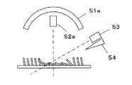
- the measuring devices 20 and 21 when measuring the color development amount of the printing material P having the ground tissue region and the raised tissue region, diffuse illuminations 51a and 51b are respectively arranged on the upper side and the lower side of the printing material P.
- the optical sensors 52a and 52b for measuring the optical reflectance from the upper side and the lower side of the printed material P are respectively disposed, and the optical sensor 53 for measuring the optical reflectance from the oblique direction of the printed material P is disposed. Good.
- the diffuse illuminations 51a and 51b and the optical sensors 52a and 52b may be arranged on either the upper side or the lower side of the printing material P.
- the illumination 51a and the optical sensor 52a may be arranged only on the upper side of the printing material P.
- the measuring devices 20 and 21 measure the optical characteristics by disposing an air nozzle 54 that blows air from an oblique direction so as to horizontally tilt the raised tissue of the portion measured by the optical sensor 53. Accuracy can be improved.
- the printing apparatuses according to the first to sixth embodiments include the inkjet head 4, the inkjet head 5, the inkjet head 32, the color material ink atomizer 31, the color material ink atomizer 33, the color material ink atomizer 34, and the corona.
- two of the processing devices 41 are used for printing on the substrate P, three or more may be used in combination. Further, the present invention can be applied to the case where the printing material P is composed of three or more regions having different coloring characteristics.
- the color development characteristics of each region of the printing material P are determined by a combination of ink type, ink supply device, and ink supply parameters.
- the color development characteristics of each region can also be described by the landing rate of the color material in the ink.
- the K / S value at each wavelength can be adopted. These combinations can be stored in the print characteristic DB2.
- the color development characteristics of each region can be achieved by combining these device parameters with the ink supply device and ink supply parameters for color ink. Determined. These can be stored in the print characteristic DB2.
- the optimum droplet supply device and ink type are selected from a plurality of droplet supply devices and a plurality of ink types corresponding to a plurality of areas of the printing object to be printed. By selecting and performing printing with the ink supply parameters suitable for them, it is possible to realize the color reproduction target color.
- Example 1 In the printing apparatus according to the first embodiment, using the data stored in the print characteristic DB 2, each region of the brushed tissue and the ground tissue is formed by using one type of ink with the inkjet head 4 for large droplet printing and the inkjet head 5 for small droplet printing.
- An example of obtaining the ink supply parameter in the case where the ink is ejected to cause color development is shown below.
- the print characteristic DB 2 stores the landing ratio of each region when the print amount normalized by the maximum print amount of each of the inkjet heads 4 and 5 is ejected as data.
- Example 2 In the printing apparatus according to the fourth embodiment, when data stored in the print characteristic DB 2 is used and ink and a hydrophilization treatment liquid are ejected by the ink jet head 4 and the ink jet head 32 to develop each region of the raised tissue and the ground tissue.
- An example of obtaining the ink supply parameter and the hydrophilizing liquid supply parameter is shown below.
- Stored data as shown in Table 2 is useful for processing for changing the landing ratio of a specific area of the substrate P such as when using a hydrophilic treatment liquid.
- the printing characteristic DB 2 stores the landing rate of each region corresponding to the combination of the printing amount of the hydrophilizing liquid from the inkjet head 32 and the printing amount of the ink from the inkjet head 4. Yes.
Landscapes
- Engineering & Computer Science (AREA)
- Textile Engineering (AREA)
- Ink Jet (AREA)
- Particle Formation And Scattering Control In Inkjet Printers (AREA)
- Color, Gradation (AREA)
- Treatment Of Fiber Materials (AREA)
- Coating Apparatus (AREA)
- Printers Characterized By Their Purpose (AREA)
Abstract
互いに異なる発色特性を有する複数の領域からなる被印字物を再現目標色に発色させることができる印字装置を提供することを課題とする。 被印字物Pの地組織の領域および起毛組織の領域にそれぞれ対応するインクジェットヘッド4および5から対応する領域に発色のための液滴を供給して被印字物Pを再現目標色に発色させる。
Description
この発明は、被印字物に印字する印字装置および印字方法に係り、特に、互いに異なる発色特性を有する複数の領域からなる被印字物に印字する印字装置および印字方法に関する。
布、織物などは広く日用品に使用されており、その形態や素材も多様化している。このような多様化した織物などに印字を行い、再現目標色と同様の発色をさせることが求められている。
多様化した織物としては、例えば、織物の地組織の表面を毛羽立てた起毛織物、地組織の表面にパイルを織り出したパイル織物、地組織に樹脂製のフック・ループ部を取り付けた面ファスナーなどがある。このような起毛部分と地組織、パイル部分と地組織、ファスナーのフック・ループ部分と地組織等の互いに異なる複数の領域を有する被印字物においては、領域毎にインクの着弾率、インクの発色率などが異なるため、同様の印字条件で印字してもそれぞれの領域で異なる発色を示す。また、これら複数の領域は非常に近接して配置されていたり、厚み方向に配置されていたりするため、例えばインクジェット印字において打滴位置の制御で所望の領域の着色を制御することは困難である。このような問題に対し、それぞれの領域の発色特性に対応して印字条件を変えることで再現目標色と同様に発色させる方法がとられている。
多様化した織物としては、例えば、織物の地組織の表面を毛羽立てた起毛織物、地組織の表面にパイルを織り出したパイル織物、地組織に樹脂製のフック・ループ部を取り付けた面ファスナーなどがある。このような起毛部分と地組織、パイル部分と地組織、ファスナーのフック・ループ部分と地組織等の互いに異なる複数の領域を有する被印字物においては、領域毎にインクの着弾率、インクの発色率などが異なるため、同様の印字条件で印字してもそれぞれの領域で異なる発色を示す。また、これら複数の領域は非常に近接して配置されていたり、厚み方向に配置されていたりするため、例えばインクジェット印字において打滴位置の制御で所望の領域の着色を制御することは困難である。このような問題に対し、それぞれの領域の発色特性に対応して印字条件を変えることで再現目標色と同様に発色させる方法がとられている。
例えば、特許文献1には、起毛織物の起毛組織の太さ、長さ等によってノズルの径を変えてインクを打滴することで、起毛組織の先端断面の発色を均一にすることが提案されている。
しかしながら、起毛組織のみの発色を均一にしても、起毛織物、パイル織物、およびファスナーを有する織物など互いに異なる発色特性を有する複数の領域からなる被印字物に印字を行う場合に、被印字物の各領域について再現目標色と同様に発色させることは困難である。
この発明は、このような従来の問題点を解消するためになされたもので、互いに異なる発色特性を有する複数の領域からなる被印字物を再現目標色に発色させることができる印字装置および印字方法を提供することを目的とする。
上記目的を達成するために、本発明に係る印字装置は、互いに異なる発色特性を有する複数の領域からなる被印字物に印字を行って再現目標色に発色させる印字装置であって、前記被印字物の複数の領域にそれぞれ優位に発色させるための液滴を供給する複数の液滴供給装置と、前記被印字物を前記再現目標色に発色させるように前記複数の液滴供給装置からそれぞれ供給する液滴の供給条件を演算する演算部と、前記複数の液滴供給装置を駆動する駆動部と、前記演算部で演算された供給条件に基づいて、前記駆動部を制御する制御部とを有するものである。
ここで、前記複数の液滴供給装置は、インクジェット法によりインクの液滴を供給する第1のインクジェット装置を含むことができる。また、前記複数の液滴供給装置は、前記第1のインクジェット装置とは異なる方向に向けてインクジェット法によりインクの液滴を供給する第2のインクジェット装置を含んでもよい。また、前記複数の液滴供給装置は、霧化したインクの液滴を供給する霧化器を含んでもよい。また、前記複数の液滴供給装置は、前記被印字物を親水化させる親水化液の液滴を供給する親水化液供給装置を含んでもよい。また、前記複数の液滴供給装置は、霧化したインクの液滴を帯電させて供給する第1の霧化器と、霧化したインクの液滴を帯電させずに供給する第2の霧化器とを含むこともできる。
また、前記演算部は、前記被印字物の各領域の情報および前記被印字物に印字しようとする前記再現目標色の情報に基づいて、前記液滴供給装置からそれぞれ供給する液滴の供給条件を演算することを有することができる。
また、前記被印字物の各領域をそれぞれ対応する前記液滴供給装置で発色させる際の発色情報を予め格納したデータベースをさらに有し、前記演算部は、印字しようとする前記被印字物の各領域の情報および前記再現目標色の情報に基づいて、前記被印字物の各領域が前記再現目標色に発色するような前記発色情報を前記データベースから抽出して、前記液滴供給装置から供給される液滴の供給条件を演算してもよい。
また、前記被印字物の各領域をそれぞれ対応する前記液滴供給装置で発色させる際の発色情報を予め格納したデータベースをさらに有し、前記演算部は、印字しようとする前記被印字物の各領域の情報および前記再現目標色の情報に基づいて、前記被印字物の各領域が前記再現目標色に発色するような前記発色情報を前記データベースから抽出して、前記液滴供給装置から供給される液滴の供給条件を演算してもよい。
また、前記複数の液滴供給装置からの液滴の供給により発色した前記被印字物を測色する計測装置と、前記計測装置で前記被印字物を測色した結果を前記演算部に入力する計測値入力部とをさらに有し、前記演算部は、前記被印字物を測色した結果と前記再現目標色の情報に基づいて、演算された各液滴供給装置からの液滴の供給条件を補正し、前記制御部は、前記演算部で補正された供給条件で液滴が供給されるように、前記駆動部を制御してもよい。
また、本発明に係る印字装置は、互いに異なる発色特性を有する複数の領域からなる被印字物に印字を行って再現目標色に発色させる印字装置であって、前記被印字物の複数の領域のうち少なくとも1つの領域をコロナ処理により親水化させるコロナ処理装置と、前記被印字物にインクジェット法によりインクの液滴を供給するインクジェット装置と、前記コロナ処理装置と前記インクジェット装置を制御して前記被印字物を前記再現目標色に発色させるインク供給装置とを有するものである。
ここで、前記被印字物の複数の領域は、起毛組織からなる領域を含んでもよい。また、前記被印字物の複数の領域は、パイル組織からなる領域を含んでもよい。また、前記被印字物の複数の領域は、ファスナーフック・ループからなる領域を含んでもよい。
また、本発明に係る印字方法は、互いに異なる発色特性を有する複数の領域からなる被印字物に印字を行って再現目標色に発色させる印字方法であって、前記被印字物の複数の領域にそれぞれ優位にインクを供給する液滴供給装置から発色のための液滴を供給して前記被印字物を前記再現目標色に発色させるものである。
ここで、互いに異なる発色特性を有する複数の領域からなる被印字物に印字を行って再現目標色に発色させる印字方法であって、前記被印字物の複数の領域のうち少なくとも1つの領域をコロナ処理により親水化し、前記被印字物にインクジェット法によりインクの液滴を供給して前記再現目標色に発色させることができる。
ここで、互いに異なる発色特性を有する複数の領域からなる被印字物に印字を行って再現目標色に発色させる印字方法であって、前記被印字物の複数の領域のうち少なくとも1つの領域をコロナ処理により親水化し、前記被印字物にインクジェット法によりインクの液滴を供給して前記再現目標色に発色させることができる。
本発明によれば、互いに異なる発色特性を有する複数の領域からなる被印字物を再現目標色に発色させることができる。
以下に、添付の図面に示す好適な実施形態に基づいて、この発明を詳細に説明する。
実施形態1
図1に、本発明の実施形態1に係る印字装置の構成を示す。印字装置は、供給条件演算部1と、印字特性データベース(DB)2と、制御部9と、印字駆動部3と、インクジェットヘッド4および5とを有する。
図1に、本発明の実施形態1に係る印字装置の構成を示す。印字装置は、供給条件演算部1と、印字特性データベース(DB)2と、制御部9と、印字駆動部3と、インクジェットヘッド4および5とを有する。
供給条件演算部1には、互いに異なる発色特性を有する地組織の領域および起毛組織の領域からなる被印字物Pの情報および被印字物Pに印字しようとする印字画像の再現目標色の情報が入力データとしてオペレータにより入力される。被印字物Pの情報としては、被印字物Pの各領域における素材、原繊維径、繊維数などに関する情報が含まれる。再現目標色の情報には、被印字物Pの各領域における再現目標色の色度などに関する情報が含まれる。
供給条件演算部1は、印字特性DB2と接続されている。供給条件演算部1は、被印字物Pの情報および再現目標色の情報に基づいて印字特性DB2を検索し、被印字物Pの領域ごとに再現目標色に最も近い発色を示すインクジェットヘッド4および5のインク種とインク供給パラメータを抽出する。ここで、インク供給パラメータとしては、インクジェットヘッド4および5に出力する電圧、周波数、波形などが含まれる。また、供給条件演算部1は、被印字物Pの移動速度に基づいてインクジェットヘッド4および5のそれぞれからインクを打滴する時点を演算する。
供給条件演算部1は、印字特性DB2と接続されている。供給条件演算部1は、被印字物Pの情報および再現目標色の情報に基づいて印字特性DB2を検索し、被印字物Pの領域ごとに再現目標色に最も近い発色を示すインクジェットヘッド4および5のインク種とインク供給パラメータを抽出する。ここで、インク供給パラメータとしては、インクジェットヘッド4および5に出力する電圧、周波数、波形などが含まれる。また、供給条件演算部1は、被印字物Pの移動速度に基づいてインクジェットヘッド4および5のそれぞれからインクを打滴する時点を演算する。
供給条件演算部1は、制御部9と接続されている。制御部9は、供給条件演算部1で抽出されたインク種とインク供給パラメータを示す電気信号をインクジェットヘッド4および5からそのインクを打滴すべき時点で印字駆動部3に入力することで、被印字物Pへの印字を制御する。
制御部9は、印字駆動部3と接続されている。印字駆動部3は、制御部9から入力された電気信号に応じてインクジェットヘッド4および5をそれぞれ駆動する。
印字駆動部3は、インクジェットヘッド4および5と接続されている。インクジェットヘッド4および5は、例えば圧電素子の伸縮動作を利用してインクを打滴する、いわゆるインクジェット方式の印字ヘッドであり、4種類のインクY,M,C,Kを打滴する。インクジェットヘッド4は、被印字物Pに対して垂直方向からインクを着弾させるものである。例えばインクジェットヘッド4は被印字物Pの地組織の領域と起毛組織の領域の両方に印字出来るが、起毛組織の領域より地組織の領域に優位に印字出来るものである。一方、インクジェットヘッド5は、被印字物Pに対して斜め方向からインクを着弾させるものであり、例えば被印字物Pの起毛組織の領域を優位に発色させるものである。
制御部9は、印字駆動部3と接続されている。印字駆動部3は、制御部9から入力された電気信号に応じてインクジェットヘッド4および5をそれぞれ駆動する。
印字駆動部3は、インクジェットヘッド4および5と接続されている。インクジェットヘッド4および5は、例えば圧電素子の伸縮動作を利用してインクを打滴する、いわゆるインクジェット方式の印字ヘッドであり、4種類のインクY,M,C,Kを打滴する。インクジェットヘッド4は、被印字物Pに対して垂直方向からインクを着弾させるものである。例えばインクジェットヘッド4は被印字物Pの地組織の領域と起毛組織の領域の両方に印字出来るが、起毛組織の領域より地組織の領域に優位に印字出来るものである。一方、インクジェットヘッド5は、被印字物Pに対して斜め方向からインクを着弾させるものであり、例えば被印字物Pの起毛組織の領域を優位に発色させるものである。
また、被印字物Pの移動方向に対し、インクジェットヘッド4および5の下流側には、インク中の色材を被印字物Pに先着させるための処理装置が配置される。例えば、被印字物Pがポリエステル繊維の場合、色材として分散染料を用い、処理装置として加熱装置6と、還元洗浄装置7と、乾燥装置8が順次配置される。加熱装置6は、印字が完了した被印字物Pの加熱処理を行うものである。還元洗浄装置7は、被印字物Pの還元洗浄を行うためのもので、例えば、ハイドロサルファイトなどの還元洗浄助剤が用いられる。乾燥装置8は、被印字物Pを乾燥するためのものである。
また、被印字物Pがポリエステル以外の絹、綿、毛繊維の場合にはそれぞれ適した色材を用い、適した処理装置が配置される。
また、被印字物Pがポリエステル以外の絹、綿、毛繊維の場合にはそれぞれ適した色材を用い、適した処理装置が配置される。
図2に、印字特性DB2に格納されている情報について示す。印字特性DB2には、インクジェットヘッド4および5に対して、複数のインク種と、複数のインク供給パラメータと、複数の被印字物の領域種とのそれぞれの組み合わせに対応する発色情報が予め格納されている。供給条件演算部1は、被印字物Pの各領域について再現目標色に最も近い発色を示す発色情報を選択し、その発色情報を満たすインクジェットヘッド4および5のインク種とインク供給パラメータとの組み合わせを抽出する。なお、発色情報としては、インクの着弾率、発色率などを採用することができる。ここで、着弾率は、被印字物の各領域にインクを打滴した際の打滴インク量と被印字物の各領域に捕捉された色材量との比率で示したものである。また、発色率は、被印字物の各領域にある単位量でインクを打滴した際に、被印字物の各領域の発色の程度を光学反射率またはK/Sなどで表したものである。K/Sで表す場合には、例えば1色のインクで発色させる時は下記式(1)に示される。また、例えば4色など複数のインクを混合して発色させる時は下記式(2)で示される。
K/Sには以下のような性質があることがクベルカ・ムンクにより示されている。
K/S=(1-Rc)2/2Rc ・・・ (1)
(K/S)mix
=Jy(K/S)y+Jm(K/S)m+Jc(K/S)c+Jk(K/S)k ・・・ (2)
K/S=(1-Rc)2/2Rc ・・・ (1)
(K/S)mix
=Jy(K/S)y+Jm(K/S)m+Jc(K/S)c+Jk(K/S)k ・・・ (2)
なお、式(1)は各波長において、色材による吸収強度K、被印字物からの光散乱強度S、反射率Rcの関係を示す。また、式(2)において、(K/S)mixは複数の色材が印字され混合された領域のK/Sを示し、(K/S)y、(K/S)m、(K/S)c、(K/S)kはそれぞれ4色の色材が単位量付着したときのK/Sを示し、Jy、Jm、Jc、Jkはそれぞれ4色の色材の被印字物への付着量を示す。すなわち、複数の色材を混合した場合のK/Sは、各色材のK/Sの付着量に応じた線形和で表される。この線形性を利用し各色材が任意量付着したときの発色が計算で求められることになる。
また、この明細書において、「インク」とは、色材を所定濃度で溶解または分散させたものと定義する。さらに、「色材」は、発色を行うものであって、染料、顔料、色素、塗料などを含むものとする。
また、この明細書において、「インク」とは、色材を所定濃度で溶解または分散させたものと定義する。さらに、「色材」は、発色を行うものであって、染料、顔料、色素、塗料などを含むものとする。
次に、図1に示した印字装置の動作を説明する。
まず、供給条件演算部1が、オペレータにより入力された被印字物Pの情報および被印字物Pに印字しようとする印字画像の再現目標色の情報に基づき、印字特性DB2を検索する。供給条件演算部1は、印字特性DB2の被印字物の領域種の情報から被印字物Pにおける地組織および起毛組織の各領域と同様の種類を示すものをそれぞれ検索する。
続いて、供給条件演算部1は、被印字物Pの地組織及び起毛組織の各領域の再現目標から発色を示す発色情報目標に変換する。発色情報としては、インク中のYMCK色材の地組織及び起毛組織の各領域への着弾量としても良い。また、発色情報は、地組織及び起毛組織の各領域の光学反射率から求まるL*a*b*のような測色値にしても良い。
供給条件演算部1は、印字特性DB2のデータを用い、地組織及び起毛組織の各領域の発色情報が発色情報目標となるようなインクジェットヘッド4及び5の全インク種(YMCK×2=8種)のインク供給パラメータを求める。
なお、供給条件演算部1は、印字特性DB2のデータを用い、インクジェットヘッド4及び5の全インク種のインク供給パラメータを与えたときの発色を予測し、発色情報を計算し、発色情報が発色情報目標になるようなインク供給パラメータの組み合わせを最適化手法で求めることも出来る。具体的にはクベルカ・ムンクの式を使用してK/Sを利用し、印字量と発色情報の関係を求め、シンプレックス法による線形計画法、逐次近似法、遺伝的方法等の最適化手法が使用できる。また、供給条件演算部1は、印字特性DB2の中の発色再現目標に近いインク供給パラメータの組み合わせを複数求めそれらの補間により最適なインク供給パラメータを求めることも出来る。
続いて、供給条件演算部1は、被印字物Pの地組織及び起毛組織の各領域の再現目標から発色を示す発色情報目標に変換する。発色情報としては、インク中のYMCK色材の地組織及び起毛組織の各領域への着弾量としても良い。また、発色情報は、地組織及び起毛組織の各領域の光学反射率から求まるL*a*b*のような測色値にしても良い。
供給条件演算部1は、印字特性DB2のデータを用い、地組織及び起毛組織の各領域の発色情報が発色情報目標となるようなインクジェットヘッド4及び5の全インク種(YMCK×2=8種)のインク供給パラメータを求める。
なお、供給条件演算部1は、印字特性DB2のデータを用い、インクジェットヘッド4及び5の全インク種のインク供給パラメータを与えたときの発色を予測し、発色情報を計算し、発色情報が発色情報目標になるようなインク供給パラメータの組み合わせを最適化手法で求めることも出来る。具体的にはクベルカ・ムンクの式を使用してK/Sを利用し、印字量と発色情報の関係を求め、シンプレックス法による線形計画法、逐次近似法、遺伝的方法等の最適化手法が使用できる。また、供給条件演算部1は、印字特性DB2の中の発色再現目標に近いインク供給パラメータの組み合わせを複数求めそれらの補間により最適なインク供給パラメータを求めることも出来る。
続いて、供給条件演算部1は、図示しない被印字物移動手段による被印字物Pの移動速度に基づいて、インクジェットヘッド4およびインクジェットヘッド5からのインクが被印字物Pに着弾する位置に被印字物Pの地組織の領域および起毛組織の領域が到達する時点を演算する。
このようにして供給条件演算部1で抽出された被印字物Pの領域ごとのインク種とインク供給パラメータならびに供給条件演算部1で演算されたインクを打滴すべき時点は、制御部9に出力される。制御部9は、供給条件演算部1がそれぞれのインク種のインクを打滴すべき時点で印字駆動部3にインク供給パラメータを出力すると、印字駆動部3は、インク供給パラメータに応じた駆動信号をインク種に対応するインクジェットヘッド4およびインクジェットヘッド5のヘッド部にそれぞれ出力し、被印字物Pの各領域にインクを打滴する。
これにより、互いに異なる発色特性を有する地組織の領域および起毛組織の領域からなる被印字物Pを再現目標色と同様に発色させることができる。
被印字物Pの移動に連動し、被印字物Pの領域ごとに抽出されたインク供給パラメータでインクの打滴が全ての領域について繰り返し行われていく。印字された被印字物Pは、加熱装置6で加熱された後、還元洗浄装置7で還元洗浄され、乾燥装置8で乾燥される。供給条件演算部1に入力された印字画像を全て印字した被印字物Pについて、加熱処理、乾燥洗浄処理、および乾燥処理がされた時点で終了する。
本実施形態の印字装置によれば、地組織の領域に優位に印字できるインクジェットヘッド4と起毛組織の領域に優位に印字できるインクジェットヘッド5をそれぞれ備えると共にインクジェットヘッド4およびインクジェットヘッド5を制御してそれぞれに対応した被印字物Pの領域に印字することで、互いに異なる発色特性を有する地組織の領域および起毛組織の領域からなる被印字物Pを再現目標色と同様に発色させることができる。
実施形態2
図3に実施形態2に係る印字装置の構成を示す。この実施形態2は、被印字物Pに印字した後に被印字物Pにおける光学特性を計測し、その計測結果から再現目標色と同様の発色を実現するように補正して印字するものである。本実施形態に係る印字装置は、図1に示した実施形態1の印字装置において、被印字物Pの進行方向に対し乾燥装置8の下流側に計測装置20,21を配置し、計測装置20,21に印字結果計測値入力部22を接続すると共に、この印字結果計測値入力部22を供給条件演算部1に接続したものである。
計測装置20および21は、被印字物Pの表側および裏側からそれぞれ光学特性を計測し、発色量を測定するためのものであり、積分球を有する拡散測色器または拡散測色器で校正した光学センサなどから構成される。印字結果計測値入力部22は、計測装置20および21において得られた計測値を供給条件演算部1に入力することで、被印字物Pの印字結果をフィードバックするものである。供給条件演算部1は、印字結果計測値入力部22から入力された計測値が再現目標色と同様の発色を実現するように補正した打滴すべきインクの供給条件値を被印字物Pの各領域について求めるものである。
図3に実施形態2に係る印字装置の構成を示す。この実施形態2は、被印字物Pに印字した後に被印字物Pにおける光学特性を計測し、その計測結果から再現目標色と同様の発色を実現するように補正して印字するものである。本実施形態に係る印字装置は、図1に示した実施形態1の印字装置において、被印字物Pの進行方向に対し乾燥装置8の下流側に計測装置20,21を配置し、計測装置20,21に印字結果計測値入力部22を接続すると共に、この印字結果計測値入力部22を供給条件演算部1に接続したものである。
計測装置20および21は、被印字物Pの表側および裏側からそれぞれ光学特性を計測し、発色量を測定するためのものであり、積分球を有する拡散測色器または拡散測色器で校正した光学センサなどから構成される。印字結果計測値入力部22は、計測装置20および21において得られた計測値を供給条件演算部1に入力することで、被印字物Pの印字結果をフィードバックするものである。供給条件演算部1は、印字結果計測値入力部22から入力された計測値が再現目標色と同様の発色を実現するように補正した打滴すべきインクの供給条件値を被印字物Pの各領域について求めるものである。
まず、実施形態1と同様にして入力された被印字物Pの情報および被印字物Pに印字しようとする印字画像の発色情報に基づき、供給条件演算部1が印字特性DB2を検索する。供給条件演算部1は、被印字物Pの各領域について、再現目標色に最も近い発色を示す発色情報を選択し、その発色情報を満たすインクジェットヘッド4および5のインク種とインク供給パラメータとの組み合わせを抽出する。また、供給条件演算部1は、被印字物Pの移動速度に基づいてインクジェットヘッド4およびインクジェットヘッド5からインクを打滴する時点を演算する。供給条件演算部1で抽出された被印字物Pの領域ごとのインク供給パラメータおよび供給条件演算部1で演算されたインクを打滴する時点は、制御部9に入力される。
制御部9は入力されたインク供給パラメータをそれぞれのインクを打滴すべき時点で印字駆動部3に出力すると、印字駆動部3は、インク供給パラメータに応じた駆動信号をインクジェットヘッド4およびインクジェットヘッド5のヘッド部にそれぞれ出力し、被印字物Pの各領域にインクを打滴する。印字された被印字物Pは、加熱装置6で加熱された後、還元洗浄装置7で還元洗浄され、乾燥装置8で乾燥される。乾燥された被印字物Pは計測装置20および21により被印字物Pの表側と裏側からそれぞれ測色され、その計測値が被印字結果計測値入力部22を介して供給条件演算部1に入力される。
入力された計測値が再現目標色の色度の許容範囲外の場合、供給条件演算部1は、印字結果計測値入力部22から入力された計測値が再現目標色の色度に一致するように、インクジェットヘッド4およびインクジェットヘッド5の各ヘッド部から打滴すべきインクのインク供給パラメータをそれぞれ補正する。供給条件演算部1により補正されたインクのインク供給パラメータは制御部9に出力され、制御部9がインク供給パラメータに基づいて印字駆動部3によるインクジェットヘッド4およびインクジェットヘッド5の各ヘッド部の駆動を制御し、被印字物Pに印字される。なお、1度の補正で再現目標色の色度の許容範囲内に入らない場合には、許容範囲内に入るまで上記の補正を繰り返すことが好ましい。
制御部9は入力されたインク供給パラメータをそれぞれのインクを打滴すべき時点で印字駆動部3に出力すると、印字駆動部3は、インク供給パラメータに応じた駆動信号をインクジェットヘッド4およびインクジェットヘッド5のヘッド部にそれぞれ出力し、被印字物Pの各領域にインクを打滴する。印字された被印字物Pは、加熱装置6で加熱された後、還元洗浄装置7で還元洗浄され、乾燥装置8で乾燥される。乾燥された被印字物Pは計測装置20および21により被印字物Pの表側と裏側からそれぞれ測色され、その計測値が被印字結果計測値入力部22を介して供給条件演算部1に入力される。
入力された計測値が再現目標色の色度の許容範囲外の場合、供給条件演算部1は、印字結果計測値入力部22から入力された計測値が再現目標色の色度に一致するように、インクジェットヘッド4およびインクジェットヘッド5の各ヘッド部から打滴すべきインクのインク供給パラメータをそれぞれ補正する。供給条件演算部1により補正されたインクのインク供給パラメータは制御部9に出力され、制御部9がインク供給パラメータに基づいて印字駆動部3によるインクジェットヘッド4およびインクジェットヘッド5の各ヘッド部の駆動を制御し、被印字物Pに印字される。なお、1度の補正で再現目標色の色度の許容範囲内に入らない場合には、許容範囲内に入るまで上記の補正を繰り返すことが好ましい。
この実施形態2によれば、被印字物Pに印字した結果をフィードバックすることにより補正されたインク供給パラメータに基づき再び被印字物Pに印字するため、初期の計算精度が悪い場合、あるいはインク、被印字物P等の物性が経時あるいは環境で変化した場合であっても、発色量のズレあるいは変動を効果的に抑制することができる。
なお、供給条件演算部1は、印字結果のフィードバックにより補正されたインク供給パラメータを、補正の都度、印字特性DB2に蓄積する、あるいは、補正されたインク供給パラメータにより印字特性DB2に既に格納されているインク供給パラメータを更新することによって、学習機能を持たせることもできる。このように印字を繰り返すごとに学習させることで印字特性DB2に格納されている情報の精度を高めていくことができる。
実施形態3
図4に示されるように、実施形態1または2に係る印字装置において、インクジェットヘッド5の代わりに色材インク霧化器31を用いることができる。色材インク霧化器31は、超音波によりインクを霧化させて印字するものであり、少ない運動エネルギーを有するインク滴を被印字物Pに供給する。このため、色材インク霧化器31は、運動エネルギーの違いで着弾率が変化するような被印字物Pの領域を印字するのに適しており、例えば被印字物Pの起毛組織の領域を優位に発色させるのに適したものである。また、インクジェットヘッド4は、例えば被印字物Pの地組織の領域を優位に発色させるのに適したものである。
印字特性DB2には、インクジェットヘッド4および色材インク霧化器31に対して、複数のインク種と、複数のインク供給パラメータと、複数の被印字物の領域種とのそれぞれの組み合わせに対応する発色情報が予め格納されている。なお、被印字物Pは地組織の領域と起毛組織の領域からなり、起毛組織の領域は、図3において被印字物Pの下面に存在するものとする。
図4に示されるように、実施形態1または2に係る印字装置において、インクジェットヘッド5の代わりに色材インク霧化器31を用いることができる。色材インク霧化器31は、超音波によりインクを霧化させて印字するものであり、少ない運動エネルギーを有するインク滴を被印字物Pに供給する。このため、色材インク霧化器31は、運動エネルギーの違いで着弾率が変化するような被印字物Pの領域を印字するのに適しており、例えば被印字物Pの起毛組織の領域を優位に発色させるのに適したものである。また、インクジェットヘッド4は、例えば被印字物Pの地組織の領域を優位に発色させるのに適したものである。
印字特性DB2には、インクジェットヘッド4および色材インク霧化器31に対して、複数のインク種と、複数のインク供給パラメータと、複数の被印字物の領域種とのそれぞれの組み合わせに対応する発色情報が予め格納されている。なお、被印字物Pは地組織の領域と起毛組織の領域からなり、起毛組織の領域は、図3において被印字物Pの下面に存在するものとする。
実施形態1と同様にして、供給条件演算部1が、被印字物Pの各領域について、再現目標色に最も近い発色を示すようにインクジェットヘッド4および色材インク霧化器31のインク種とインク供給パラメータとの組み合わせを印字特性DB2から抽出・演算する。供給条件演算部1で抽出された被印字物Pの領域ごとのインク供給パラメータは、制御部9に入力される。制御部9は入力されたインク供給パラメータをそれぞれのインクを打滴すべき時点で印字駆動部3に出力すると、印字駆動部3は、インク供給パラメータに応じた駆動信号をインクジェットヘッド4および色材インク霧化器31にそれぞれ出力する。印字駆動部3からの駆動信号の出力により、インクジェットヘッド4は被印字物Pの地組織の領域にインクを供給し、色材インク霧化器31は被印字物Pの起毛組織の領域にインクを供給する。
本実施形態の印字装置によれば、地組織の領域に対応したインクジェットヘッド4と起毛組織の領域に対応した色材インク霧化器31をそれぞれ備えると共にインクジェットヘッド4および色材インク霧化器31を制御してそれぞれに対応した被印字物Pの領域に印字することで、互いに異なる発色特性を有する地組織の領域および起毛組織の領域からなる被印字物Pを再現目標色と同様に発色させることができる。
実施形態4
図5に示すように、実施形態1または2に係る印字装置において、インクジェットヘッド5の代わりにインクジェットヘッド32を用いてもよい。インクジェットヘッド32は、被印字物Pの移動方向に対してインクジェットヘッド4の上流側に配置され、インクジェット方式により親水化処理液を打滴して被印字物Pを親水化処理する。このように、インクジェットヘッド32は、例えばファスナーフック・ループ等のオープン領域(繊維が密に組織化されていない領域)に親水化処理液を打滴し、インクの着弾率を向上させる。このため、インクジェットヘッド32および4の併用は、例えばファスナーフック・ループを含む被印字物Pを印字するのに適したものであり、インクジェットヘッド4のみの使用は、例えば被印字物Pの地組織の領域を再現目標色に発色させるのに適したものである。なお、親水化処理液としては、親水性高分子化合物のアラビアガム、グアガム、ローカーストビンガム、シラツガム、アルギン酸ナトリウム、カルボキシメチルセルローズ、ポリアクリル酸ナトリウムなどが界面活性剤と共に用いられる。
印字特性DB2には、インクジェットヘッド4および32に対して、複数のインク種と、複数のインク供給パラメータと、複数の親水化液供給パラメータと、複数の被印字物の領域種とのそれぞれの組み合わせに対応する発色情報が予め格納されている。ここで、親水化液供給パラメータとしては、インクジェットヘッド32に出力する電圧、周波数、波形などが含まれる。なお、被印字物Pは、地組織の領域とファスナーフック・ループの領域からなるものとする。
インクジェットヘッド32による、親水化処理液自身では発色を起こさないが、インクジェットヘッド4の打滴による色材のファスナーフック・ループの領域への着弾比率を増すことになる。印字特性DB2には、親水化液供給パラメータとYMCKインク供給パラメータとの組み合わせと、これらを組み合わせた打滴による色材のファスナーフック・ループの領域への着弾比率の変化が含まれる。
図5に示すように、実施形態1または2に係る印字装置において、インクジェットヘッド5の代わりにインクジェットヘッド32を用いてもよい。インクジェットヘッド32は、被印字物Pの移動方向に対してインクジェットヘッド4の上流側に配置され、インクジェット方式により親水化処理液を打滴して被印字物Pを親水化処理する。このように、インクジェットヘッド32は、例えばファスナーフック・ループ等のオープン領域(繊維が密に組織化されていない領域)に親水化処理液を打滴し、インクの着弾率を向上させる。このため、インクジェットヘッド32および4の併用は、例えばファスナーフック・ループを含む被印字物Pを印字するのに適したものであり、インクジェットヘッド4のみの使用は、例えば被印字物Pの地組織の領域を再現目標色に発色させるのに適したものである。なお、親水化処理液としては、親水性高分子化合物のアラビアガム、グアガム、ローカーストビンガム、シラツガム、アルギン酸ナトリウム、カルボキシメチルセルローズ、ポリアクリル酸ナトリウムなどが界面活性剤と共に用いられる。
印字特性DB2には、インクジェットヘッド4および32に対して、複数のインク種と、複数のインク供給パラメータと、複数の親水化液供給パラメータと、複数の被印字物の領域種とのそれぞれの組み合わせに対応する発色情報が予め格納されている。ここで、親水化液供給パラメータとしては、インクジェットヘッド32に出力する電圧、周波数、波形などが含まれる。なお、被印字物Pは、地組織の領域とファスナーフック・ループの領域からなるものとする。
インクジェットヘッド32による、親水化処理液自身では発色を起こさないが、インクジェットヘッド4の打滴による色材のファスナーフック・ループの領域への着弾比率を増すことになる。印字特性DB2には、親水化液供給パラメータとYMCKインク供給パラメータとの組み合わせと、これらを組み合わせた打滴による色材のファスナーフック・ループの領域への着弾比率の変化が含まれる。
実施形態1と同様にして、供給条件演算部1が、被印字物Pの情報および再現目標色の情報に基づき、印字特性DB2を検索する。供給条件演算部1は、印字特性DB2の被印字物の領域種の情報から被印字物Pにおける地組織およびファスナーフック・ループの各領域と同様の種類を示すものをそれぞれ検索する。続いて、供給条件演算部1は、被印字物Pの地組織の領域について再現目標色に最も近い発色を示す発色情報を選択し、その発色情報を満たすインクジェットヘッド4のインク種とインク供給パラメータとの組み合わせを抽出する。同様に、供給条件演算部1は、被印字物Pのファスナーフック・ループの領域について再現目標色に最も近い発色を示す発色情報を選択し、その発色情報を満たすインクジェットヘッド32の親水化液供給パラメータとインクジェットヘッド4のインク種とインクジェットヘッド4のインク供給パラメータとの組み合わせを抽出する。供給条件演算部1で抽出された親水化液供給パラメータとインク供給パラメータは、制御部9に入力される。制御部9は入力された親水化液供給パラメータまたはインク供給パラメータを親水化処理液またはインクをそれぞれ打滴すべき時点で印字駆動部3に出力すると、印字駆動部3は、親水化液供給パラメータまたはインク供給パラメータに応じた駆動信号をインクジェットヘッド32またはインクジェットヘッド4のヘッド部にそれぞれ出力する。これにより、被印字物Pのファスナーフック・ループの領域にインクジェットヘッド32から親水化処理液が供給された後、インクジェットヘッド4からインクが供給されると共に、被印字物Pの地組織の領域にインクジェットヘッド4からインクが供給される。
本実施形態の印字装置によれば、単独では地組織の領域に優位に印字出来るインクジェットヘッド4とファスナーフック・ループの領域の印字比率を改善するインクジェットヘッド32の併用を制御して被印字物Pの各領域を印字することで、互いに異なる発色特性を有する地組織の領域およびファスナーフック・ループの領域からなる被印字物Pを再現目標色と同様に発色させることができる。
本実施形態では、インクジェットヘッド4は水を主体としたインクを想定し、親水化液を用いたが非水系インクの場合においても使用インクとの親和性の高い液を用いることが出来る。
なお、本実施形態では、被印字物Pの親水化処理を親水化液により行う方法を示したが、インクジェットヘッド32の代わりに被印字物Pの表面を改質するコロナ処理装置あるいはプラズマ照射装置を用いてもよい。図6に、インクジェットヘッド32の代わりにコロナ処理装置41を用いた印字装置を示す。コロナ処理装置41は、被印字物Pの移動方向に対してインクジェットヘッド4の上流側に配置され、電圧を印加する電源装置42と電源装置42から電圧が印加されてコロナ放電を発生させる放電電極43とを有する。コロナ処理装置41は、放電電極43の間にコロナ放電を発生させることにより、被印字物Pの複数の領域のうち少なくとも1つの領域をコロナ処理により優位に親水化させ、インクの着弾比率を向上させる。さらに被印字物Pの親水化効果を上げるために、親水化処理においてコロナ処理装置41とインクジェットヘッド32を併用させても良い。
また、図7に示すように、本実施形態の印字装置において、インクジェット方式により浸透液を被印字物Pに打滴するためのインクジェットヘッド10を印字駆動部3に新たに接続することもできる。インクジェットヘッド10は、被印字物Pの移動方向に対してインクジェットヘッド32の下流側で且つインクジェットヘッド4の上流側に配置される。被印字物Pのファスナーフック・ループの領域にインクジェットヘッド32から親水化処理液を供給すると共に、被印字物Pにおいて繊維が密に組織化されている地組織の領域に浸透液を供給する。その後、インクジェットヘッド4から被印字物Pにインクが供給されると、地組織の領域にインクジェットヘッド10から予め浸透液が供給されていることによりインクジェットヘッド4から供給された色材インクの地組織の領域への着弾比率が低下し、ファスナーフック・ループの領域のようなオープン領域に優先的に色材インクを着弾させることができる。なお、「浸透液」は、色材を溶解または分散させるための溶媒または分散媒を示し、「インク」は、色材を浸透液に所定濃度で溶解または分散させたものを示す。
本実施形態では、インクジェットヘッド4は水を主体としたインクを想定し、親水化液を用いたが非水系インクの場合においても使用インクとの親和性の高い液を用いることが出来る。
なお、本実施形態では、被印字物Pの親水化処理を親水化液により行う方法を示したが、インクジェットヘッド32の代わりに被印字物Pの表面を改質するコロナ処理装置あるいはプラズマ照射装置を用いてもよい。図6に、インクジェットヘッド32の代わりにコロナ処理装置41を用いた印字装置を示す。コロナ処理装置41は、被印字物Pの移動方向に対してインクジェットヘッド4の上流側に配置され、電圧を印加する電源装置42と電源装置42から電圧が印加されてコロナ放電を発生させる放電電極43とを有する。コロナ処理装置41は、放電電極43の間にコロナ放電を発生させることにより、被印字物Pの複数の領域のうち少なくとも1つの領域をコロナ処理により優位に親水化させ、インクの着弾比率を向上させる。さらに被印字物Pの親水化効果を上げるために、親水化処理においてコロナ処理装置41とインクジェットヘッド32を併用させても良い。
また、図7に示すように、本実施形態の印字装置において、インクジェット方式により浸透液を被印字物Pに打滴するためのインクジェットヘッド10を印字駆動部3に新たに接続することもできる。インクジェットヘッド10は、被印字物Pの移動方向に対してインクジェットヘッド32の下流側で且つインクジェットヘッド4の上流側に配置される。被印字物Pのファスナーフック・ループの領域にインクジェットヘッド32から親水化処理液を供給すると共に、被印字物Pにおいて繊維が密に組織化されている地組織の領域に浸透液を供給する。その後、インクジェットヘッド4から被印字物Pにインクが供給されると、地組織の領域にインクジェットヘッド10から予め浸透液が供給されていることによりインクジェットヘッド4から供給された色材インクの地組織の領域への着弾比率が低下し、ファスナーフック・ループの領域のようなオープン領域に優先的に色材インクを着弾させることができる。なお、「浸透液」は、色材を溶解または分散させるための溶媒または分散媒を示し、「インク」は、色材を浸透液に所定濃度で溶解または分散させたものを示す。
実施形態5
図8に示すように、実施形態1または2に係る印字装置において、インクジェットヘッド4および5の代わりに色材インク霧化器33および34を用いてもよい。色材インク霧化器33は、超音波によりインクを霧化させた後に帯電させずに印字するものである。また、色材インク霧化器34は、被印字物Pの移動方向に対して色材インク霧化器33の上流側に配置され、インク滴を超音波により霧化させた後にインク滴を帯電させて印字するものである。色材インク霧化器34のインクは、インクを吐出するインク吐出部側と被印字物P側との間に電界発生装置35により電界を発生させることで帯電させる。これにより、色材インク霧化器34は、被印字物Pのインク滴と反対に帯電した領域に優位にインクを着弾させることができ、例えば被印字物Pの起毛組織の領域に所望の帯電を与えることで、再現目標色に優位に発色させるのに適したものである。一方、色材インク霧化器33は、例えば被印字物Pの地組織の領域を再現目標色に発色させるのに適したものである。なお、被印字物Pを選択的に帯電させるには、例えば、コロナ帯電器などのイオン発生器を用いて起毛部先端に帯電させる方法、摩擦帯電により起毛部を帯電させる方法、界面活性剤の供給等で繊維の電気抵抗を下げることで界面活性剤を供給していない部分を帯電させる方法などが利用できる。
印字特性DB2には、色材インク霧化器33および色材インク霧化器34に対して、複数のインク種と、複数のインク供給パラメータと、複数の被印字物の領域種とのそれぞれの組み合わせに対応する発色情報が予め格納されている。なお、被印字物Pは地組織の領域と起毛組織の領域からなり、起毛組織の領域は、図3において被印字物Pの下面に存在するものとする。
図8に示すように、実施形態1または2に係る印字装置において、インクジェットヘッド4および5の代わりに色材インク霧化器33および34を用いてもよい。色材インク霧化器33は、超音波によりインクを霧化させた後に帯電させずに印字するものである。また、色材インク霧化器34は、被印字物Pの移動方向に対して色材インク霧化器33の上流側に配置され、インク滴を超音波により霧化させた後にインク滴を帯電させて印字するものである。色材インク霧化器34のインクは、インクを吐出するインク吐出部側と被印字物P側との間に電界発生装置35により電界を発生させることで帯電させる。これにより、色材インク霧化器34は、被印字物Pのインク滴と反対に帯電した領域に優位にインクを着弾させることができ、例えば被印字物Pの起毛組織の領域に所望の帯電を与えることで、再現目標色に優位に発色させるのに適したものである。一方、色材インク霧化器33は、例えば被印字物Pの地組織の領域を再現目標色に発色させるのに適したものである。なお、被印字物Pを選択的に帯電させるには、例えば、コロナ帯電器などのイオン発生器を用いて起毛部先端に帯電させる方法、摩擦帯電により起毛部を帯電させる方法、界面活性剤の供給等で繊維の電気抵抗を下げることで界面活性剤を供給していない部分を帯電させる方法などが利用できる。
印字特性DB2には、色材インク霧化器33および色材インク霧化器34に対して、複数のインク種と、複数のインク供給パラメータと、複数の被印字物の領域種とのそれぞれの組み合わせに対応する発色情報が予め格納されている。なお、被印字物Pは地組織の領域と起毛組織の領域からなり、起毛組織の領域は、図3において被印字物Pの下面に存在するものとする。
実施形態1と同様にして、供給条件演算部1が、被印字物Pの各領域について、再現目標色に最も近い発色を示すように色材インク霧化器33および色材インク霧化器34のインク種とインク供給パラメータとの組み合わせを印字特性DB2から抽出する。供給条件演算部1で抽出された被印字物Pの領域ごとのインク供給パラメータは、制御部9に入力される。制御部9は入力されたインク供給パラメータをそれぞれのインクを打滴すべき時点で印字駆動部3に出力すると、印字駆動部3は、インク供給パラメータに応じた駆動信号を色材インク霧化器33および色材インク霧化器34にそれぞれ出力する。この時、色材インク霧化器34で霧化されたインク滴は電界発生装置35により帯電されている。印字駆動部3からの駆動信号の出力により、色材インク霧化器33は被印字物Pの地組織の領域にインクを供給し、色材インク霧化器34は被印字物Pの起毛組織の領域にインクを供給する。
本実施形態の印字装置によれば、地組織の領域に対応した色材インク霧化器33と起毛組織の領域に対応した色材インク霧化器34をそれぞれ備えると共に色材インク霧化器33および34を制御してそれぞれに対応した被印字物Pの領域に印字することで、互いに異なる発色特性を有する地組織の領域および起毛組織の領域からなる被印字物Pを再現目標色と同様に発色させることができる。
実施形態6
実施形態2に係る印字装置において、計測装置20および21は、被印字物Pの各領域の特徴に適したものが利用できる。例えば、図9に示すように、地組織の領域および起毛組織の領域を有する被印字物Pの発色量を測定する場合、被印字物Pの上側および下側に拡散照明51aおよび51bをそれぞれ配置すると共に被印字物Pの上側および下側から光学反射率を測定する光学センサ52aおよび52bをそれぞれ配置し、被印字物Pの斜め方向から光学反射率を測定する光学センサ53を配置してもよい。
なお、被印字物Pの光学特性を計測できれば拡散照明51aおよび51bならびに光学センサ52aおよび52bは被印字物Pの上側および下側の一方に配置すればよく、例えば図10に示すように、拡散照明51aと光学センサ52aを被印字物Pの上側のみに配置してもよい。
また、計測装置20および21は、例えば、図11に示すように、光学センサ53が計測する部分の起毛組織を水平に倒すように斜め方向からエアを吹き付けるエアノズル54を配置して光学特性の計測の精度を向上させることができる。
実施形態2に係る印字装置において、計測装置20および21は、被印字物Pの各領域の特徴に適したものが利用できる。例えば、図9に示すように、地組織の領域および起毛組織の領域を有する被印字物Pの発色量を測定する場合、被印字物Pの上側および下側に拡散照明51aおよび51bをそれぞれ配置すると共に被印字物Pの上側および下側から光学反射率を測定する光学センサ52aおよび52bをそれぞれ配置し、被印字物Pの斜め方向から光学反射率を測定する光学センサ53を配置してもよい。
なお、被印字物Pの光学特性を計測できれば拡散照明51aおよび51bならびに光学センサ52aおよび52bは被印字物Pの上側および下側の一方に配置すればよく、例えば図10に示すように、拡散照明51aと光学センサ52aを被印字物Pの上側のみに配置してもよい。
また、計測装置20および21は、例えば、図11に示すように、光学センサ53が計測する部分の起毛組織を水平に倒すように斜め方向からエアを吹き付けるエアノズル54を配置して光学特性の計測の精度を向上させることができる。
なお、実施形態1~6の印字装置は、インクジェットヘッド4、インクジェットヘッド5、インクジェットヘッド32、色材インク霧化器31、色材インク霧化器33、色材インク霧化器34、およびコロナ処理装置41のうち2つを用いて被印字物Pに印字しているが、3つ以上を組み合わせて用いてもよい。また被印字物Pが発色特性の異なる3つ以上の領域からなる場合に適用することも可能である。
また、被印字物Pの各領域の発色特性は、インク種、インク供給装置、インク供給パラメータの組み合わせにより決まる。各領域の発色特性はインク中の色材の着弾率で記述することも出来る。あるいは各波長におけるK/S値を採用することも出来る。これらの組み合わせを印字特性DB2に格納することが出来る。
また、親水化液等の着弾率に影響を与えるインク種、インク供給装置については、これらの装置パラメータと、色材インクのインク供給装置、インク供給パラメータ等との組み合わせで各領域の発色特性が決まる。これらを含めて印字特性DB2に格納することが出来る。
このような印字特性DB2を利用すれば、印字対象となる被印字物の複数の領域にそれぞれ対応して、複数の液滴供給装置および複数のインク種から最適な液滴供給装置およびインク種を選択し、それらに適合したインク供給パラメータで印字を行うことにより、再現目標色の発色を実現することが可能となる。
また、親水化液等の着弾率に影響を与えるインク種、インク供給装置については、これらの装置パラメータと、色材インクのインク供給装置、インク供給パラメータ等との組み合わせで各領域の発色特性が決まる。これらを含めて印字特性DB2に格納することが出来る。
このような印字特性DB2を利用すれば、印字対象となる被印字物の複数の領域にそれぞれ対応して、複数の液滴供給装置および複数のインク種から最適な液滴供給装置およびインク種を選択し、それらに適合したインク供給パラメータで印字を行うことにより、再現目標色の発色を実現することが可能となる。
実施例1
実施形態1の印字装置において、印字特性DB2に格納されたデータを使い、1種のインクを大滴印字用のインクジェットヘッド4と小滴印字用のインクジェットヘッド5により起毛組織と地組織の各領域に打滴して発色させる場合のインク供給パラメータを求める例を以下に示す。
印字特性DB2には、表1に示すように、インクジェットヘッド4及び5のそれぞれ最大印字量で規格化した印字量を打滴した場合の各領域の着弾率がデータとして格納されている。
地組織の領域を23%、起毛組織の領域を27%の印字を行い起毛組織の領域を若干濃くしたい場合、インクジェットヘッド4で20%印字を、インクジェットヘッド5で30%印字を行えばよいことがわかる。この計算には公知の最適化計算手法、印字特性DB2に格納されていないデータについては公知の補間手法を使うことが出来る。
また、複数のインク種を利用する場合には、印字特性DB2に格納されているインクジェットヘッド4および5による各領域の発色を各波長のK/Sで表すことができる。
実施形態1の印字装置において、印字特性DB2に格納されたデータを使い、1種のインクを大滴印字用のインクジェットヘッド4と小滴印字用のインクジェットヘッド5により起毛組織と地組織の各領域に打滴して発色させる場合のインク供給パラメータを求める例を以下に示す。
印字特性DB2には、表1に示すように、インクジェットヘッド4及び5のそれぞれ最大印字量で規格化した印字量を打滴した場合の各領域の着弾率がデータとして格納されている。
地組織の領域を23%、起毛組織の領域を27%の印字を行い起毛組織の領域を若干濃くしたい場合、インクジェットヘッド4で20%印字を、インクジェットヘッド5で30%印字を行えばよいことがわかる。この計算には公知の最適化計算手法、印字特性DB2に格納されていないデータについては公知の補間手法を使うことが出来る。
また、複数のインク種を利用する場合には、印字特性DB2に格納されているインクジェットヘッド4および5による各領域の発色を各波長のK/Sで表すことができる。

実施例2
実施形態4の印字装置において、印字特性DB2に格納されたデータを使い、インクおよび親水化処理液をインクジェットヘッド4およびインクジェットヘッド32により打滴して起毛組織と地組織の各領域を発色させる場合のインク供給パラメータおよび親水化液供給パラメータを求める例を以下に示す。
親水化処理液を使用する場合のような被印字物Pの特定領域の着弾比率を変化させる処理については、表2に示すような格納データが有用である。印字特性DB2には、表2に示すように、インクジェットヘッド32からの親水化処理液の印字量と、インクジェットヘッド4からのインクの印字量の組み合わせに対応する各領域の着弾率が格納されている。
実施例1と同様にして、被印字物Pの各領域の発色が再現目標色となるようなインク供給パラメータおよび親水化液供給パラメータをこの印字特性DB2を使い求めることが出来る。
実施形態4の印字装置において、印字特性DB2に格納されたデータを使い、インクおよび親水化処理液をインクジェットヘッド4およびインクジェットヘッド32により打滴して起毛組織と地組織の各領域を発色させる場合のインク供給パラメータおよび親水化液供給パラメータを求める例を以下に示す。
親水化処理液を使用する場合のような被印字物Pの特定領域の着弾比率を変化させる処理については、表2に示すような格納データが有用である。印字特性DB2には、表2に示すように、インクジェットヘッド32からの親水化処理液の印字量と、インクジェットヘッド4からのインクの印字量の組み合わせに対応する各領域の着弾率が格納されている。
実施例1と同様にして、被印字物Pの各領域の発色が再現目標色となるようなインク供給パラメータおよび親水化液供給パラメータをこの印字特性DB2を使い求めることが出来る。

1 供給条件演算部、2 印字特性データベース、3 印字駆動部、4,5,32 インクジェットヘッド、6 加熱装置、7 還元洗浄装置、8 乾燥装置、9 制御部、20,21 計測装置、22 印字結果計測値入力部、31,33,34 色材インク霧化器、35 電界発生装置、41 コロナ処理装置、42 電源装置、43 放電電極、51a,51b 拡散照明、52a,52b,53 光学センサ、54 エアノズル。
Claims (15)
- 互いに異なる発色特性を有する複数の領域からなる被印字物に印字を行って再現目標色に発色させる印字装置であって、
前記被印字物の複数の領域にそれぞれ優位に発色させるための液滴を供給する複数の液滴供給装置と、
前記被印字物を前記再現目標色に発色させるように前記複数の液滴供給装置からそれぞれ供給する液滴の供給条件を演算する演算部と、
前記複数の液滴供給装置を駆動する駆動部と、
前記演算部で演算された供給条件に基づいて、前記駆動部を制御する制御部と
を有することを特徴とする印字装置。 - 前記複数の液滴供給装置は、インクジェット法によりインクの液滴を供給する第1のインクジェット装置を含むことを特徴とする請求項1に記載の印字装置。
- 前記複数の液滴供給装置は、前記第1のインクジェット装置とは異なる方向に向けてインクジェット法によりインクの液滴を供給する第2のインクジェット装置を含むことを特徴とする請求項2に記載の印字装置。
- 前記複数の液滴供給装置は、霧化したインクの液滴を供給する霧化器を含むことを特徴とする請求項2に記載の印字装置。
- 前記複数の液滴供給装置は、前記被印字物を親水化させる親水化液の液滴を供給する親水化液供給装置を含むことを特徴とする請求項2に記載の印字装置。
- 前記複数の液滴供給装置は、霧化したインクの液滴を帯電させて供給する第1の霧化器と、霧化したインクの液滴を帯電させずに供給する第2の霧化器とを含む請求項1に記載の印字装置。
- 前記演算部は、前記被印字物の各領域の情報および前記被印字物に印字しようとする前記再現目標色の情報に基づいて、前記液滴供給装置からそれぞれ供給する液滴の供給条件を演算することを特徴とする請求項1~6のいずれかに記載の印字装置。
- 前記被印字物の各領域をそれぞれ対応する前記液滴供給装置で発色させる際の発色情報を予め格納したデータベースをさらに有し、
前記演算部は、印字しようとする前記被印字物の各領域の情報および前記再現目標色の情報に基づいて、前記被印字物の各領域が前記再現目標色に発色するような前記発色情報を前記データベースから抽出して、前記液滴供給装置から供給される液滴の供給条件を演算することを特徴とする請求項7に記載の印字装置。 - 前記複数の液滴供給装置からの液滴の供給により発色した前記被印字物を測色する計測装置と、
前記計測装置で前記被印字物を測色した結果を前記演算部に入力する計測値入力部とをさらに有し、
前記演算部は、前記被印字物を測色した結果と前記再現目標色の情報に基づいて、演算された各液滴供給装置からの液滴の供給条件を補正し、
前記制御部は、前記演算部で補正された供給条件で液滴が供給されるように、前記駆動部を制御することを特徴とする請求項7または8に記載の印字装置。 - 互いに異なる発色特性を有する複数の領域からなる被印字物に印字を行って再現目標色に発色させる印字装置であって、
前記被印字物の複数の領域のうち少なくとも1つの領域をコロナ処理により親水化させるコロナ処理装置と、
前記被印字物にインクジェット法によりインクの液滴を供給するインクジェット装置と、
前記コロナ処理装置と前記インクジェット装置を制御して前記被印字物を前記再現目標色に発色させるインク供給装置と
を有することを特徴とする印字装置。 - 前記被印字物の複数の領域は、起毛組織からなる領域を含むことを特徴とする請求項1~10のいずれかに記載の印字装置。
- 前記被印字物の複数の領域は、パイル組織からなる領域を含むことを特徴とする請求項1~11のいずれかに記載の印字装置。
- 前記被印字物の複数の領域は、ファスナーフック・ループからなる領域を含むことを特徴とする請求項1~12のいずれかに記載の印字装置。
- 互いに異なる発色特性を有する複数の領域からなる被印字物に印字を行って再現目標色に発色させる印字方法であって、
前記被印字物の複数の領域にそれぞれ優位にインクを供給する液滴供給装置から発色のための液滴を供給して前記被印字物を前記再現目標色に発色させることを特徴とする印字方法。 - 互いに異なる発色特性を有する複数の領域からなる被印字物に印字を行って再現目標色に発色させる印字方法であって、
前記被印字物の複数の領域のうち少なくとも1つの領域をコロナ処理により親水化し、
前記被印字物にインクジェット法によりインクの液滴を供給して前記再現目標色に発色させることを特徴とする印字方法。
Priority Applications (2)
| Application Number | Priority Date | Filing Date | Title |
|---|---|---|---|
| CN2011800167466A CN102822407A (zh) | 2010-03-31 | 2011-01-19 | 印刷机和印刷方法 |
| EP11762312.4A EP2554732A4 (en) | 2010-03-31 | 2011-01-19 | Printer and printing method |
Applications Claiming Priority (2)
| Application Number | Priority Date | Filing Date | Title |
|---|---|---|---|
| JP2010-080444 | 2010-03-31 | ||
| JP2010080444A JP5620135B2 (ja) | 2010-03-31 | 2010-03-31 | 印字装置および印字方法 |
Publications (1)
| Publication Number | Publication Date |
|---|---|
| WO2011122071A1 true WO2011122071A1 (ja) | 2011-10-06 |
Family
ID=44711824
Family Applications (1)
| Application Number | Title | Priority Date | Filing Date |
|---|---|---|---|
| PCT/JP2011/050836 Ceased WO2011122071A1 (ja) | 2010-03-31 | 2011-01-19 | 印字装置および印字方法 |
Country Status (4)
| Country | Link |
|---|---|
| EP (1) | EP2554732A4 (ja) |
| JP (1) | JP5620135B2 (ja) |
| CN (1) | CN102822407A (ja) |
| WO (1) | WO2011122071A1 (ja) |
Families Citing this family (6)
| Publication number | Priority date | Publication date | Assignee | Title |
|---|---|---|---|---|
| JP2017008459A (ja) * | 2015-06-25 | 2017-01-12 | 株式会社キョーエース | 起毛布の製造方法及び起毛布の製造装置 |
| JP2017013408A (ja) | 2015-07-02 | 2017-01-19 | 株式会社リコー | 被処理物改質装置、被処理物改質システム、画像形成システムおよび画像形成方法 |
| JP7172521B2 (ja) * | 2018-12-03 | 2022-11-16 | セイコーエプソン株式会社 | インク量決定方法およびインク量決定システム |
| CN112285271A (zh) * | 2020-10-22 | 2021-01-29 | 东来涂料技术(上海)股份有限公司 | 一种有机溶剂水分含量判定方法 |
| JP7501311B2 (ja) * | 2020-10-30 | 2024-06-18 | セイコーエプソン株式会社 | 情報処理装置、情報処理方法及びそのプログラム |
| JP2026003162A (ja) * | 2024-06-24 | 2026-01-13 | コニカミノルタ株式会社 | インクジェット捺染装置、インクジェット捺染方法及びプログラム |
Citations (8)
| Publication number | Priority date | Publication date | Assignee | Title |
|---|---|---|---|---|
| JPS5231187A (en) * | 1975-09-01 | 1977-03-09 | Teijin Seiki Co Ltd | Continuous dyeing method and apparatus for yarn * cloth and like |
| JPS616363A (ja) * | 1984-06-15 | 1986-01-13 | 住江織物株式会社 | 長尺生地の連続染色装置 |
| JPH0369631A (ja) * | 1989-08-03 | 1991-03-26 | Seiren Co Ltd | 有毛布帛着色物とその製法 |
| JP2003247179A (ja) * | 2002-02-26 | 2003-09-05 | Upepo & Maji Inc | インクジェット方式での捺染方法 |
| JP2004090505A (ja) * | 2002-09-02 | 2004-03-25 | Omron Corp | 写真シール自動作成方法とその装置、及び印刷媒体 |
| WO2004094151A1 (ja) * | 2003-04-23 | 2004-11-04 | Shima Seiki Manufacturing Limited | インクジェット式プリント装置およびプログラム |
| JP2005290639A (ja) * | 2004-04-05 | 2005-10-20 | Ricoh Co Ltd | 画像形成方法及び画像形成装置 |
| JP2005536377A (ja) * | 2002-08-20 | 2005-12-02 | ザック、モシェ | マルチプリントヘッドプリンタ |
Family Cites Families (13)
| Publication number | Priority date | Publication date | Assignee | Title |
|---|---|---|---|---|
| JPS5231187B1 (ja) * | 1970-12-23 | 1977-08-12 | ||
| JP3376027B2 (ja) * | 1992-12-04 | 2003-02-10 | キヤノン株式会社 | 布帛用画像形成装置、布帛用画像形成方法および画像形成がなされた布帛からなる物品、並びにプリント物の製造方法 |
| JP3299341B2 (ja) * | 1993-06-12 | 2002-07-08 | セーレン株式会社 | インクジェット染色用有毛布帛及びその染色方法 |
| JP3453423B2 (ja) * | 1994-01-29 | 2003-10-06 | セーレン株式会社 | 面ファスナー及びそのインクジェット印写方法 |
| JPH07276673A (ja) * | 1994-04-07 | 1995-10-24 | Canon Inc | インクジェット記録装置、および該装置における色味調整方法 |
| JP3382439B2 (ja) * | 1994-12-29 | 2003-03-04 | キヤノン株式会社 | インクジェットプリント装置およびインクジェットプリント方法 |
| JPH1181162A (ja) * | 1997-08-27 | 1999-03-26 | Ishizaka Shoji Kk | 帯状布帛の連続捺染方法及び装置 |
| US6588879B2 (en) * | 2001-12-03 | 2003-07-08 | Supersample Corporation | Method for ink jet printing a digital image on a textile, the system and apparatus for practicing the method, and products produced by the system and apparatus using the method |
| JP2005231098A (ja) * | 2004-02-18 | 2005-09-02 | Brother Ind Ltd | 画像編集装置及び画像編集方法 |
| JP2006203708A (ja) * | 2005-01-21 | 2006-08-03 | Ricoh Co Ltd | 画像処理装置 |
| CN1322197C (zh) * | 2005-05-18 | 2007-06-20 | 东华大学 | 电晕活化接枝亲水基团的化纤、纱线及其织物的工艺 |
| JP2008221522A (ja) * | 2007-03-09 | 2008-09-25 | Canon Inc | インクジェット記録装置 |
| JP2009165968A (ja) * | 2008-01-16 | 2009-07-30 | Kgk Engineering Corp | ベルト状被洗浄物の洗浄方法及び洗浄装置 |
-
2010
- 2010-03-31 JP JP2010080444A patent/JP5620135B2/ja not_active Expired - Fee Related
-
2011
- 2011-01-19 EP EP11762312.4A patent/EP2554732A4/en not_active Withdrawn
- 2011-01-19 WO PCT/JP2011/050836 patent/WO2011122071A1/ja not_active Ceased
- 2011-01-19 CN CN2011800167466A patent/CN102822407A/zh active Pending
Patent Citations (9)
| Publication number | Priority date | Publication date | Assignee | Title |
|---|---|---|---|---|
| JPS5231187A (en) * | 1975-09-01 | 1977-03-09 | Teijin Seiki Co Ltd | Continuous dyeing method and apparatus for yarn * cloth and like |
| JPS616363A (ja) * | 1984-06-15 | 1986-01-13 | 住江織物株式会社 | 長尺生地の連続染色装置 |
| JPH0369631A (ja) * | 1989-08-03 | 1991-03-26 | Seiren Co Ltd | 有毛布帛着色物とその製法 |
| JP2799595B2 (ja) | 1989-08-03 | 1998-09-17 | セーレン株式会社 | 有毛布帛着色物とその製法 |
| JP2003247179A (ja) * | 2002-02-26 | 2003-09-05 | Upepo & Maji Inc | インクジェット方式での捺染方法 |
| JP2005536377A (ja) * | 2002-08-20 | 2005-12-02 | ザック、モシェ | マルチプリントヘッドプリンタ |
| JP2004090505A (ja) * | 2002-09-02 | 2004-03-25 | Omron Corp | 写真シール自動作成方法とその装置、及び印刷媒体 |
| WO2004094151A1 (ja) * | 2003-04-23 | 2004-11-04 | Shima Seiki Manufacturing Limited | インクジェット式プリント装置およびプログラム |
| JP2005290639A (ja) * | 2004-04-05 | 2005-10-20 | Ricoh Co Ltd | 画像形成方法及び画像形成装置 |
Non-Patent Citations (1)
| Title |
|---|
| See also references of EP2554732A4 * |
Also Published As
| Publication number | Publication date |
|---|---|
| JP2011212852A (ja) | 2011-10-27 |
| JP5620135B2 (ja) | 2014-11-05 |
| CN102822407A (zh) | 2012-12-12 |
| EP2554732A4 (en) | 2018-06-20 |
| EP2554732A1 (en) | 2013-02-06 |
Similar Documents
| Publication | Publication Date | Title |
|---|---|---|
| JP5620135B2 (ja) | 印字装置および印字方法 | |
| US9193149B2 (en) | Aqueous ink jet blanket | |
| CN102381026B (zh) | 故障记录部件校正参数的选择表、确定方法及装置和图像形成装置 | |
| US9132659B2 (en) | Image recording apparatus, control method thereof, and recording medium | |
| US20130050368A1 (en) | Ink Jet UV Pinning for Control of Gloss | |
| EP4052917B1 (en) | Liquid discharge apparatus, printer, and liquid discharge method | |
| JP2016530119A (ja) | 輻射線硬化性相変化インクの画像を適用するための方法 | |
| JP5685285B2 (ja) | 印字装置および印字方法 | |
| KR20200132812A (ko) | 수성 잉크젯 블랭킷 | |
| CN103358708B (zh) | 喷墨记录设备和喷墨记录方法 | |
| JP5713992B2 (ja) | インクジェット印字方法および装置 | |
| JP2011206961A (ja) | インクジェット印字方法および装置 | |
| DE602004003437T2 (de) | Tintenzusammensetzung und Methode für den Tintenstrahldruck | |
| JP2023019647A (ja) | インク及びインクジェット記録装置 | |
| JP7059638B2 (ja) | 記録装置、記録方法、及び、記録プログラム | |
| EP4556232A1 (en) | Liquid discharge head, liquid discharge device, liquid discharge apparatus, liquid discharge method, and non-transitory recording medium | |
| EP4563361A1 (en) | Liquid discharge apparatus, liquid discharge method, and carrier medium | |
| JP2006231520A (ja) | インクジェット式プリント装置およびプログラム | |
| JP2003153888A (ja) | 医用画像記録システム | |
| LOW | Mettu et al.(43) Pub. Date: Jun. 19, 2014 | |
| JP2005119312A (ja) | 液体噴射記録装置及び記録液体 | |
| Billah | Inkjet Printed Photo-Responsive Textiles For Conventional And Hightech Applications | |
| Kulube | Trichromatic Ink-Jet Printing for Cotton Textiles | |
| JP2004090452A (ja) | インクジェットヘッド | |
| JP2001239744A (ja) | インクジェット記録方法 |
Legal Events
| Date | Code | Title | Description |
|---|---|---|---|
| WWE | Wipo information: entry into national phase |
Ref document number: 201180016746.6 Country of ref document: CN |
|
| 121 | Ep: the epo has been informed by wipo that ep was designated in this application |
Ref document number: 11762312 Country of ref document: EP Kind code of ref document: A1 |
|
| WWE | Wipo information: entry into national phase |
Ref document number: 2011762312 Country of ref document: EP |
|
| NENP | Non-entry into the national phase |
Ref country code: DE |