WO2011122105A1 - Dispositif de commande pour dispositif d'entraînement de moteur électrique - Google Patents
Dispositif de commande pour dispositif d'entraînement de moteur électrique Download PDFInfo
- Publication number
- WO2011122105A1 WO2011122105A1 PCT/JP2011/052400 JP2011052400W WO2011122105A1 WO 2011122105 A1 WO2011122105 A1 WO 2011122105A1 JP 2011052400 W JP2011052400 W JP 2011052400W WO 2011122105 A1 WO2011122105 A1 WO 2011122105A1
- Authority
- WO
- WIPO (PCT)
- Prior art keywords
- control
- field
- voltage
- command value
- value
- Prior art date
- Legal status (The legal status is an assumption and is not a legal conclusion. Google has not performed a legal analysis and makes no representation as to the accuracy of the status listed.)
- Ceased
Links
Images




Classifications
-
- H—ELECTRICITY
- H02—GENERATION; CONVERSION OR DISTRIBUTION OF ELECTRIC POWER
- H02P—CONTROL OR REGULATION OF ELECTRIC MOTORS, ELECTRIC GENERATORS OR DYNAMO-ELECTRIC CONVERTERS; CONTROLLING TRANSFORMERS, REACTORS OR CHOKE COILS
- H02P27/00—Arrangements or methods for the control of AC motors characterised by the kind of supply voltage
- H02P27/04—Arrangements or methods for the control of AC motors characterised by the kind of supply voltage using variable-frequency supply voltage, e.g. inverter or converter supply voltage
- H02P27/06—Arrangements or methods for the control of AC motors characterised by the kind of supply voltage using variable-frequency supply voltage, e.g. inverter or converter supply voltage using DC to AC converters or inverters
- H02P27/08—Arrangements or methods for the control of AC motors characterised by the kind of supply voltage using variable-frequency supply voltage, e.g. inverter or converter supply voltage using DC to AC converters or inverters with pulse width modulation
-
- H—ELECTRICITY
- H02—GENERATION; CONVERSION OR DISTRIBUTION OF ELECTRIC POWER
- H02P—CONTROL OR REGULATION OF ELECTRIC MOTORS, ELECTRIC GENERATORS OR DYNAMO-ELECTRIC CONVERTERS; CONTROLLING TRANSFORMERS, REACTORS OR CHOKE COILS
- H02P21/00—Arrangements or methods for the control of electric machines by vector control, e.g. by control of field orientation
- H02P21/0003—Control strategies in general, e.g. linear type, e.g. P, PI, PID, using robust control
- H02P21/0021—Control strategies in general, e.g. linear type, e.g. P, PI, PID, using robust control using different modes of control depending on a parameter, e.g. the speed
-
- H—ELECTRICITY
- H02—GENERATION; CONVERSION OR DISTRIBUTION OF ELECTRIC POWER
- H02P—CONTROL OR REGULATION OF ELECTRIC MOTORS, ELECTRIC GENERATORS OR DYNAMO-ELECTRIC CONVERTERS; CONTROLLING TRANSFORMERS, REACTORS OR CHOKE COILS
- H02P21/00—Arrangements or methods for the control of electric machines by vector control, e.g. by control of field orientation
- H02P21/0085—Arrangements or methods for the control of electric machines by vector control, e.g. by control of field orientation specially adapted for high speeds, e.g. above nominal speed
- H02P21/0089—Arrangements or methods for the control of electric machines by vector control, e.g. by control of field orientation specially adapted for high speeds, e.g. above nominal speed using field weakening
-
- H—ELECTRICITY
- H02—GENERATION; CONVERSION OR DISTRIBUTION OF ELECTRIC POWER
- H02P—CONTROL OR REGULATION OF ELECTRIC MOTORS, ELECTRIC GENERATORS OR DYNAMO-ELECTRIC CONVERTERS; CONTROLLING TRANSFORMERS, REACTORS OR CHOKE COILS
- H02P21/00—Arrangements or methods for the control of electric machines by vector control, e.g. by control of field orientation
- H02P21/06—Rotor flux based control involving the use of rotor position or rotor speed sensors
Definitions
- Patent Document 1 discloses an electric motor that shifts from sinusoidal PWM control to overmodulation PWM control and further to rectangular wave control as the rotational speed of the motor increases and the induced voltage increases.
- the technology of the control device of the driving device is described.
- the modulation rate which is the ratio of the effective value of the fundamental wave component of the AC voltage waveform to the DC power supply voltage (system voltage)
- the upper limit of the modulation rate is 0.61 in the sinusoidal PWM control.
- overmodulation PWM control can increase the modulation rate to a range of 0.61 to 0.78
- rectangular wave control has a maximum modulation rate of 0.78.
- the loss of the AC motor and the motor driving device when the normal field / pulse width modulation control mode for executing the pulse width modulation control together with the normal field control is executed is defined as a normal time loss, and the rectangular shape is set together with the strong field control.
- the strong field / rectangular wave control mode for executing the wave control is executed, the loss of the AC motor and the motor driving device is set as the strong field time loss, and the strong field time loss is smaller than the normal time loss.
- the upper limit in the direction of increasing the field magnetic flux in the field adjustment command value range is the adjustment command threshold value.
- the rotation speed threshold value is determined based on the target torque and the DC voltage. According to this configuration, it is possible to set an appropriate rotation speed threshold value according to the target torque and the DC voltage.
- the voltage command value can be appropriately determined by current feedback control based on the deviation between the actual current value detected by the current sensor or the like and the current command value after adjustment by the field adjustment command value. it can.
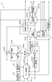
- Each of the switching elements E1 to E6 performs an on / off operation according to the switching control signals S1 to S6 output from the control device 2.
- the inverter 6 converts the DC voltage Vdc into an AC voltage and supplies it to the electric motor 4 to cause the electric motor 4 to output a torque corresponding to the target torque TM.
- each of the switching elements E1 to E6 performs a switching operation according to PWM control or rectangular wave control, which will be described later, according to the switching control signals S1 to S6.
- the switching control signals S1 to S6 are gate drive signals that drive the gates of the switching elements E1 to E6.
- the overmodulation PWM control is a PWM control in which the amplitude of the AC voltage waveforms Vu, Vv, and Vw exceeds the amplitude of the carrier waveform (triangular wave).
- overmodulation PWM control the waveform of the fundamental wave component of the output voltage waveform of the inverter 6 is distorted by making the duty ratio of each pulse large on the peak side of the fundamental wave component and smaller on the valley side than in normal PWM control, Control is performed so that the amplitude is larger than that of the normal PWM control.
- the modulation factor M can be changed in the range of “0.707 to 0.78”.
- the induced voltage of the electric motor 4 increases as the rotational speed ⁇ increases, and the AC voltage (hereinafter referred to as “required voltage”) required to drive the electric motor 4 also increases.
- the necessary voltage exceeds the maximum AC voltage that can be output from the inverter 6 by converting the DC voltage Vdc at that time (hereinafter referred to as “maximum output voltage”)
- maximum output voltage the maximum AC voltage that can be output from the inverter 6 by converting the DC voltage Vdc at that time
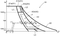
- the electric motor 4 cannot be appropriately controlled. Therefore, the field weakening / rectangular wave control mode A5 is executed in the region on the higher rotation side than the curve L1 where the modulation factor M representing the required voltage of the motor 4 with respect to the maximum output voltage based on the DC voltage Vdc reaches the maximum modulation factor Mmax.
- the necessary voltage and the maximum output voltage can be compared with each other as the effective value of the AC voltage.
- the strong field / rectangular wave control mode A3 for executing the rectangular wave control together with the strong field control is executed. To do. Further, in order to prevent the adjusted current command values Id and Iq from changing suddenly during the transition between the strong field / rectangular wave control mode A3 and the other modes, the strong field / PWM control mode A2 Is executed. Thereby, it is possible to suppress a sudden change and overshoot of the current flowing in the coil of the electric motor 4 and to suppress the vibration of the output torque of the electric motor 4 from occurring. If the normal field control is performed, the rectangular wave control can be performed while outputting the torque corresponding to the target torque TM to the electric motor 4 by executing the strong field control while the modulation factor M is lower than the maximum modulation factor Mmax. it can.
- a broken line that divides the strong field control region F is a region in which the strong field / PWM control mode A2 is executed when the rotation speed ⁇ or the target torque TM of the motor 4 changes at a predetermined change speed.
- 2 shows an example of a boundary where the strong field / rectangular wave control mode A3 is switched. The position of this boundary differs depending on the rotational speed ⁇ or the change speed of the target torque TM.
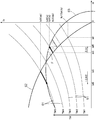
- “Iq1” which is the value of the q-axis current at the intersection is derived as the basic q-axis current command value Iqb.
- the control device 2 executes the normal field / PWM control mode A1.
- the d-axis current values (Id1, Id3, Id5) corresponding to the basic q-axis current command values Iqb (Iq1, Iq3, Iq5) obtained from the q-axis current command value map of FIG. 5 are the basic values shown in FIG. This coincides with the basic d-axis current command value Idb obtained using the d-axis current command value map. Therefore, the basic d-axis current command value Idb can be obtained from the map shown in FIG.
- the current control unit 24 performs a proportional-integral control calculation (PI control calculation) based on the d-axis current deviation ⁇ Id to derive a basic d-axis voltage command value Vzd, and also performs a proportional integration based on the q-axis current deviation ⁇ Iq.
- PI control calculation a proportional-integral control calculation based on the d-axis current deviation ⁇ Id to derive a basic d-axis voltage command value Vzd
- a control calculation is performed to derive a basic q-axis voltage command value Vzq.
- PID control calculation instead of these proportional integral control calculations.
- the d-axis voltage command value Vd and the q-axis voltage command value Vq are input to the two-phase / three-phase conversion unit 25.
- the magnetic pole position ⁇ detected by the rotation sensor 43 (see FIG. 1) is input to the two-phase / three-phase converter 25.
- the two-phase / three-phase conversion unit 25 performs two-phase / three-phase conversion on the d-axis voltage command value Vd and the q-axis voltage command value Vq using the magnetic pole position ⁇ to obtain a three-phase AC voltage command value, that is, a U-phase.
- a voltage command value Vu, a V-phase voltage command value Vv, and a W-phase voltage command value Vw are derived.
- the integral input adjustment unit 31 outputs an adjustment value Y that decreases as the modulation factor deviation ⁇ M increases in a state where the modulation factor deviation ⁇ M is equal to or greater than the intermediate deviation ⁇ Msm ( ⁇ Msm ⁇ ⁇ M).
- the adjustment value Y is proportional to the modulation factor deviation ⁇ M, and the proportionality constant is a negative value.
- the strong field start deviation ⁇ Ms is a threshold value of the modulation factor deviation ⁇ M for starting the strong field control, and is set to a value less than zero. This strong field start deviation ⁇ Ms constitutes the start condition of the strong field control together with the command modulation rate MT.
- the modulation factor deviation ⁇ M is greater than the strong field start deviation ⁇ Ms and less than zero ( ⁇ Ms ⁇ ⁇ M ⁇ 0)
- a positive value (Y> 0) is output as the adjustment value Y.
- the d-axis current adjustment command value ⁇ Id derived by 32 increases (changes in the positive direction), and the d-axis current adjustment command value ⁇ Id changes in the direction of increasing the field magnetic flux of the electric motor 4.
- a negative value (Y ⁇ 0) is output as the adjustment value Y. Therefore, the d-axis current adjustment command value ⁇ Id derived by the integrator 32 is output.
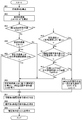
- the mode control unit 5 determines a control mode to be executed from among a plurality of control modes based on the operating state of the electric motor 4 including the rotational speed ⁇ and the target torque TM and the DC voltage Vdc, and determines the field mode according to the control mode. Each part of the control apparatus 2 including the adjustment part 8 and the voltage waveform control part 10 is controlled. Further, the mode control unit 5 determines the strong field end condition during the execution of the strong field control, and also performs the strong field end control that ends the strong field control when the strong field end condition is satisfied. .
- the integral input adjusting unit 31 is set by setting the command modulation rate MT and the strong field start deviation ⁇ Ms as described above.
- a positive adjustment value Y is output from, and a positive d-axis current adjustment command value ⁇ Id is output by the integrator 32.
- the strong field control is started.
- the mode control unit 5 first causes the voltage waveform control unit 10 to execute PWM control after starting the strong field control.
- the modulation factor M at the start of the strong field control is the overmodulation threshold Mo
- the mode control unit 5 causes the voltage waveform control unit 10 to perform overmodulation PWM control. That is, when the strong field control is started, the mode control unit 5 first executes the strong field / overmodulation PWM control mode A2b. Thereafter, the modulation factor M gradually increases due to the strong field control, and finally reaches the rectangular wave threshold value Mb. After the modulation factor M reaches the rectangular wave threshold value Mb, the mode control unit 5 causes the voltage waveform control unit 10 to execute rectangular wave control. Thereby, the strong field / rectangular wave control mode A3 is executed.
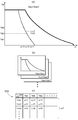
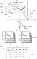
- the appropriate adjustment command threshold value ⁇ IdT can be obtained experimentally using the actual control device 2. For example, as shown in FIG. 8A, first, an arbitrary voltage is selected from the range of the DC voltage Vdc that the DC power supply 3 can take, and an arbitrary torque from the range of the target torque TM that the motor 4 can take. .
- Vdc1 is selected as the DC voltage Vdc
- the rotational speed ⁇ and the d-axis current adjustment command value ⁇ Id at the moment when the loss difference ⁇ Loss changes from positive to negative are obtained, and the rotational speed ⁇ and the DC voltage Vdc are obtained.
- the d-axis current adjustment command value ⁇ Id thus obtained is set as the adjustment command threshold value ⁇ IdT at the voltage speed ratio RV ⁇ and the target torque TM.
- the relationship among the voltage speed ratio RV ⁇ , the target torque TM, and the adjustment command threshold value ⁇ IdT is registered in the adjustment command threshold value map 35B as a map of the adjustment command threshold value ⁇ IdT.
- the field weakening / rectangular wave control mode A5 is executed from time t5 to time t8.
- Both the adjusted d-axis current command value Id and the adjusted q-axis current command value Iq set on the limit ellipse 63 increase.
- the adjusted d-axis current command value Id increases from Id8 to Id9
- the adjusted q-axis current command value Iq increases from Iq8 to Iq9.
- the d-axis current adjustment command value ⁇ Id also increases.
- the d-axis current adjustment command value ⁇ Id is gradually decreased. Also in this case, since the time until the d-axis current adjustment command value ⁇ Id becomes zero is ensured, when the strong field / rectangular wave control mode is shifted to the normal field / pulse width modulation control mode, the The field / pulse width modulation control mode can be executed.
- the AC motor 4 is a synchronous motor (IPMSM) having an embedded magnet structure that operates by three-phase AC
- IPMSM synchronous motor
- the embodiment of the present invention is not limited to this.
- a synchronous motor (SPMSM) having a surface magnet structure can be used as the AC motor 4, or other than the synchronous motor, for example, induction An electric motor or the like can also be used.
- an alternating current supplied to such an alternating current motor a single-phase other than three phases, a two-phase, or a polyphase alternating current having four or more phases can be used.
Landscapes
- Engineering & Computer Science (AREA)
- Power Engineering (AREA)
- Control Of Ac Motors In General (AREA)
Abstract
Priority Applications (2)
| Application Number | Priority Date | Filing Date | Title |
|---|---|---|---|
| CN2011800098165A CN102763321A (zh) | 2010-03-31 | 2011-02-04 | 电动机驱动装置的控制装置 |
| DE112011100226T DE112011100226T5 (de) | 2010-03-31 | 2011-02-04 | Steuerungsvorrichtung einer Motorantriebsvorrichtung |
Applications Claiming Priority (2)
| Application Number | Priority Date | Filing Date | Title |
|---|---|---|---|
| JP2010-081515 | 2010-03-31 | ||
| JP2010081515A JP5120670B2 (ja) | 2010-03-31 | 2010-03-31 | 電動機駆動装置の制御装置 |
Publications (1)
| Publication Number | Publication Date |
|---|---|
| WO2011122105A1 true WO2011122105A1 (fr) | 2011-10-06 |
Family
ID=44708830
Family Applications (1)
| Application Number | Title | Priority Date | Filing Date |
|---|---|---|---|
| PCT/JP2011/052400 Ceased WO2011122105A1 (fr) | 2010-03-31 | 2011-02-04 | Dispositif de commande pour dispositif d'entraînement de moteur électrique |
Country Status (5)
| Country | Link |
|---|---|
| US (1) | US20110241583A1 (fr) |
| JP (1) | JP5120670B2 (fr) |
| CN (1) | CN102763321A (fr) |
| DE (1) | DE112011100226T5 (fr) |
| WO (1) | WO2011122105A1 (fr) |
Families Citing this family (33)
| Publication number | Priority date | Publication date | Assignee | Title |
|---|---|---|---|---|
| WO2012011155A1 (fr) * | 2010-07-23 | 2012-01-26 | 三菱電機株式会社 | Appareil de commande et procédé de commande pour machine rotative à courant alternatif |
| BR112013001384A2 (pt) * | 2010-07-27 | 2016-05-24 | Mitsubishi Electric Corp | aparelho de controle para uma máquina giratória de ca |
| JP5718668B2 (ja) * | 2011-02-15 | 2015-05-13 | トヨタ自動車株式会社 | 回転電機駆動システム |
| DE102011085853A1 (de) * | 2011-11-07 | 2013-05-08 | Siemens Aktiengesellschaft | Verfahren und Anordnung zum Betrieb von Synchronmotoren |
| JP2014054066A (ja) * | 2012-09-06 | 2014-03-20 | Toyota Motor Corp | 回転電機駆動システムの制御装置 |
| JP5955761B2 (ja) * | 2012-12-25 | 2016-07-20 | トヨタ自動車株式会社 | 車両の制御装置 |
| JP5986013B2 (ja) * | 2013-02-19 | 2016-09-06 | 株式会社日立製作所 | 電動機駆動システム |
| JP6183165B2 (ja) * | 2013-11-12 | 2017-08-23 | サンケン電気株式会社 | 誘導電動機制御装置及び誘導電動機制御方法 |
| JP2015136237A (ja) * | 2014-01-17 | 2015-07-27 | 株式会社安川電機 | 回転電機制御装置、回転電機制御方法、及び制御マップの作成方法 |
| DE102014104488A1 (de) * | 2014-03-31 | 2015-10-01 | Robert Bosch Automotive Steering Gmbh | Verfahren zur Ansteuerung eines Elektromotors für ein Hilfskraft-Lenksystem |
| CN104079230B (zh) * | 2014-07-07 | 2016-09-28 | 神王伟国 | 异步电动机效率优化控制的方法、装置、系统及电动汽车 |
| FR3024616B1 (fr) * | 2014-07-31 | 2016-07-15 | Renault Sa | Procede et dispositif de commande du couple electromagnetique d'un groupe motopropulseur |
| US9634579B2 (en) * | 2015-04-03 | 2017-04-25 | Hamilton Sundstrand Corporation | Systems and methods for controlling inverters |
| WO2017143434A1 (fr) * | 2016-02-23 | 2017-08-31 | Canadian Space Agency | Entraînement de moteur économe en énergie avec ou sans phase à circuit ouvert |
| JP6289545B2 (ja) * | 2016-06-15 | 2018-03-07 | 三菱電機株式会社 | 回転電機の制御方法 |
| DE102016118170A1 (de) * | 2016-09-26 | 2018-03-29 | Wittenstein Se | Verfahren und vorrichtung zum abbauen elastisch gespeicherter energie |
| CN106849805A (zh) * | 2017-02-09 | 2017-06-13 | 澳特卡新能源科技(上海)有限公司 | 一种电动压缩机驱动电机的弱磁控制方法 |
| US9774279B1 (en) * | 2017-03-02 | 2017-09-26 | Borgwarner Inc. | Brushless DC motor control and method |
| DE102017217913A1 (de) * | 2017-10-09 | 2019-04-11 | Robert Bosch Gmbh | Verfahren zum Wechseln zwischen Blockansteuerung und PWM-Ansteuerung einer elektrischen Maschine |
| CN110504891B (zh) * | 2018-05-16 | 2021-09-03 | 台达电子工业股份有限公司 | 马达驱动电路及其控制方法 |
| JP7144197B2 (ja) * | 2018-06-01 | 2022-09-29 | 株式会社Soken | 回転電機の制御装置 |
| JP7357204B2 (ja) * | 2018-07-18 | 2023-10-06 | パナソニックIpマネジメント株式会社 | 電動工具、制御方法、プログラム |
| JP7052713B2 (ja) * | 2018-12-27 | 2022-04-12 | 株式会社豊田自動織機 | インバータ制御装置 |
| CN111404429B (zh) * | 2018-12-28 | 2021-11-12 | 比亚迪股份有限公司 | 一种车辆及其电机控制方法与装置、计算机可读存储介质 |
| CN110829920A (zh) * | 2019-11-04 | 2020-02-21 | 中国第一汽车股份有限公司 | 一种调制装置及系统 |
| US11456680B2 (en) * | 2020-05-08 | 2022-09-27 | Hamilton Sundstrand Corporation | Over-modulation pulse width modulation with maximum output and minimum harmonics |
| WO2022195872A1 (fr) * | 2021-03-19 | 2022-09-22 | 三菱電機株式会社 | Dispositif de commande et dispositif de conversion de puissance |
| IT202100018689A1 (it) * | 2021-07-15 | 2023-01-15 | Ferrari Spa | Procedimento ed apparato per controllare un motore elettrico |
| CN115871481B (zh) * | 2021-09-29 | 2025-05-02 | 本田技研工业株式会社 | 电动发电机控制系统及混合动力车辆 |
| US11787384B2 (en) * | 2021-11-22 | 2023-10-17 | GM Global Technology Operations LLC | Electric drive system and method |
| KR102712341B1 (ko) * | 2021-12-13 | 2024-09-30 | 현대모비스 주식회사 | 모터의 약자속 제어를 위한 데이터 맵 작성 방법 및 시스템 |
| WO2025187058A1 (fr) * | 2024-03-08 | 2025-09-12 | Astemo株式会社 | Dispositif de commande de moteur et véhicule électrique |
| US20260005631A1 (en) * | 2024-06-27 | 2026-01-01 | Renesas Electronics Corporation | Inverter control device and an inverter control method |
Citations (4)
| Publication number | Priority date | Publication date | Assignee | Title |
|---|---|---|---|---|
| JP2006081287A (ja) * | 2004-09-09 | 2006-03-23 | Aisin Aw Co Ltd | 電動駆動制御装置、電動駆動制御方法及びそのプログラム |
| JP2006311770A (ja) * | 2005-05-02 | 2006-11-09 | Toyota Motor Corp | モータ駆動システムの制御装置 |
| JP2007259538A (ja) * | 2006-03-22 | 2007-10-04 | Aisin Aw Co Ltd | 電動駆動制御装置及び電動駆動制御方法 |
| JP2008079399A (ja) * | 2006-09-20 | 2008-04-03 | Toshiba Corp | 車両制御装置 |
Family Cites Families (1)
| Publication number | Priority date | Publication date | Assignee | Title |
|---|---|---|---|---|
| JP4280573B2 (ja) * | 2003-07-31 | 2009-06-17 | トヨタ自動車株式会社 | 負荷駆動装置 |
-
2010
- 2010-03-31 JP JP2010081515A patent/JP5120670B2/ja not_active Expired - Fee Related
-
2011
- 2011-02-01 US US13/018,953 patent/US20110241583A1/en not_active Abandoned
- 2011-02-04 CN CN2011800098165A patent/CN102763321A/zh active Pending
- 2011-02-04 WO PCT/JP2011/052400 patent/WO2011122105A1/fr not_active Ceased
- 2011-02-04 DE DE112011100226T patent/DE112011100226T5/de not_active Ceased
Patent Citations (4)
| Publication number | Priority date | Publication date | Assignee | Title |
|---|---|---|---|---|
| JP2006081287A (ja) * | 2004-09-09 | 2006-03-23 | Aisin Aw Co Ltd | 電動駆動制御装置、電動駆動制御方法及びそのプログラム |
| JP2006311770A (ja) * | 2005-05-02 | 2006-11-09 | Toyota Motor Corp | モータ駆動システムの制御装置 |
| JP2007259538A (ja) * | 2006-03-22 | 2007-10-04 | Aisin Aw Co Ltd | 電動駆動制御装置及び電動駆動制御方法 |
| JP2008079399A (ja) * | 2006-09-20 | 2008-04-03 | Toshiba Corp | 車両制御装置 |
Also Published As
| Publication number | Publication date |
|---|---|
| JP2011217469A (ja) | 2011-10-27 |
| CN102763321A (zh) | 2012-10-31 |
| DE112011100226T5 (de) | 2012-10-31 |
| US20110241583A1 (en) | 2011-10-06 |
| JP5120670B2 (ja) | 2013-01-16 |
Similar Documents
| Publication | Publication Date | Title |
|---|---|---|
| JP5120670B2 (ja) | 電動機駆動装置の制御装置 | |
| JP5120669B2 (ja) | 電動機駆動装置の制御装置 | |
| JP5246508B2 (ja) | 電動機駆動装置の制御装置 | |
| JP5370769B2 (ja) | 電動機駆動装置の制御装置 | |
| JP5035641B2 (ja) | 電動機駆動装置の制御装置 | |
| JP5257365B2 (ja) | モータ制御装置とその制御方法 | |
| US7595600B2 (en) | Method and system for torque control in permanent magnet machines | |
| CN103782507B (zh) | 电动机控制系统 | |
| JP5803559B2 (ja) | 回転電機制御装置 | |
| CN103781654B (zh) | 电动机控制系统 | |
| JP5435292B2 (ja) | 制御装置 | |
| WO2012132703A1 (fr) | Appareil de commande de moteur | |
| CN102197581A (zh) | 交流电动机的控制装置以及控制方法 | |
| JP5534323B2 (ja) | 電動機制御装置 | |
| JP4008724B2 (ja) | モータ制御装置 | |
| JP2015109770A (ja) | 電動機駆動装置 | |
| WO2018139298A1 (fr) | Dispositif de commande de moteur électrique ca | |
| JP5370748B2 (ja) | 電動機駆動装置の制御装置 | |
| WO2018116668A1 (fr) | Dispositif de commande de moteur et véhicule électrique | |
| RU2463699C1 (ru) | Устройство преобразования мощности для возбуждения электродвигателя |
Legal Events
| Date | Code | Title | Description |
|---|---|---|---|
| WWE | Wipo information: entry into national phase |
Ref document number: 201180009816.5 Country of ref document: CN |
|
| 121 | Ep: the epo has been informed by wipo that ep was designated in this application |
Ref document number: 11762346 Country of ref document: EP Kind code of ref document: A1 |
|
| WWE | Wipo information: entry into national phase |
Ref document number: 112011100226 Country of ref document: DE Ref document number: 1120111002262 Country of ref document: DE |
|
| 122 | Ep: pct application non-entry in european phase |
Ref document number: 11762346 Country of ref document: EP Kind code of ref document: A1 |