WO2011122169A1 - 電源供給装置 - Google Patents
電源供給装置 Download PDFInfo
- Publication number
- WO2011122169A1 WO2011122169A1 PCT/JP2011/053736 JP2011053736W WO2011122169A1 WO 2011122169 A1 WO2011122169 A1 WO 2011122169A1 JP 2011053736 W JP2011053736 W JP 2011053736W WO 2011122169 A1 WO2011122169 A1 WO 2011122169A1
- Authority
- WO
- WIPO (PCT)
- Prior art keywords
- pack
- battery
- terminal
- pack body
- corner portion
- Prior art date
- Legal status (The legal status is an assumption and is not a legal conclusion. Google has not performed a legal analysis and makes no representation as to the accuracy of the status listed.)
- Ceased
Links
Images







Classifications
-
- H—ELECTRICITY
- H01—ELECTRIC ELEMENTS
- H01M—PROCESSES OR MEANS, e.g. BATTERIES, FOR THE DIRECT CONVERSION OF CHEMICAL ENERGY INTO ELECTRICAL ENERGY
- H01M50/00—Constructional details or processes of manufacture of the non-active parts of electrochemical cells other than fuel cells, e.g. hybrid cells
- H01M50/50—Current conducting connections for cells or batteries
- H01M50/543—Terminals
-
- H—ELECTRICITY
- H01—ELECTRIC ELEMENTS
- H01M—PROCESSES OR MEANS, e.g. BATTERIES, FOR THE DIRECT CONVERSION OF CHEMICAL ENERGY INTO ELECTRICAL ENERGY
- H01M10/00—Secondary cells; Manufacture thereof
- H01M10/05—Accumulators with non-aqueous electrolyte
- H01M10/052—Li-accumulators
- H01M10/0525—Rocking-chair batteries, i.e. batteries with lithium insertion or intercalation in both electrodes; Lithium-ion batteries
-
- H—ELECTRICITY
- H01—ELECTRIC ELEMENTS
- H01M—PROCESSES OR MEANS, e.g. BATTERIES, FOR THE DIRECT CONVERSION OF CHEMICAL ENERGY INTO ELECTRICAL ENERGY
- H01M50/00—Constructional details or processes of manufacture of the non-active parts of electrochemical cells other than fuel cells, e.g. hybrid cells
- H01M50/10—Primary casings; Jackets or wrappings
- H01M50/102—Primary casings; Jackets or wrappings characterised by their shape or physical structure
- H01M50/103—Primary casings; Jackets or wrappings characterised by their shape or physical structure prismatic or rectangular
-
- H—ELECTRICITY
- H01—ELECTRIC ELEMENTS
- H01M—PROCESSES OR MEANS, e.g. BATTERIES, FOR THE DIRECT CONVERSION OF CHEMICAL ENERGY INTO ELECTRICAL ENERGY
- H01M50/00—Constructional details or processes of manufacture of the non-active parts of electrochemical cells other than fuel cells, e.g. hybrid cells
- H01M50/10—Primary casings; Jackets or wrappings
- H01M50/147—Lids or covers
- H01M50/148—Lids or covers characterised by their shape
- H01M50/15—Lids or covers characterised by their shape for prismatic or rectangular cells
-
- H—ELECTRICITY
- H01—ELECTRIC ELEMENTS
- H01M—PROCESSES OR MEANS, e.g. BATTERIES, FOR THE DIRECT CONVERSION OF CHEMICAL ENERGY INTO ELECTRICAL ENERGY
- H01M50/00—Constructional details or processes of manufacture of the non-active parts of electrochemical cells other than fuel cells, e.g. hybrid cells
- H01M50/20—Mountings; Secondary casings or frames; Racks, modules or packs; Suspension devices; Shock absorbers; Transport or carrying devices; Holders
- H01M50/202—Casings or frames around the primary casing of a single cell or a single battery
-
- H—ELECTRICITY
- H01—ELECTRIC ELEMENTS
- H01M—PROCESSES OR MEANS, e.g. BATTERIES, FOR THE DIRECT CONVERSION OF CHEMICAL ENERGY INTO ELECTRICAL ENERGY
- H01M50/00—Constructional details or processes of manufacture of the non-active parts of electrochemical cells other than fuel cells, e.g. hybrid cells
- H01M50/20—Mountings; Secondary casings or frames; Racks, modules or packs; Suspension devices; Shock absorbers; Transport or carrying devices; Holders
- H01M50/204—Racks, modules or packs for multiple batteries or multiple cells
- H01M50/207—Racks, modules or packs for multiple batteries or multiple cells characterised by their shape
- H01M50/209—Racks, modules or packs for multiple batteries or multiple cells characterised by their shape adapted for prismatic or rectangular cells
-
- H—ELECTRICITY
- H01—ELECTRIC ELEMENTS
- H01M—PROCESSES OR MEANS, e.g. BATTERIES, FOR THE DIRECT CONVERSION OF CHEMICAL ENERGY INTO ELECTRICAL ENERGY
- H01M50/00—Constructional details or processes of manufacture of the non-active parts of electrochemical cells other than fuel cells, e.g. hybrid cells
- H01M50/20—Mountings; Secondary casings or frames; Racks, modules or packs; Suspension devices; Shock absorbers; Transport or carrying devices; Holders
- H01M50/256—Carrying devices, e.g. belts
-
- H—ELECTRICITY
- H01—ELECTRIC ELEMENTS
- H01M—PROCESSES OR MEANS, e.g. BATTERIES, FOR THE DIRECT CONVERSION OF CHEMICAL ENERGY INTO ELECTRICAL ENERGY
- H01M50/00—Constructional details or processes of manufacture of the non-active parts of electrochemical cells other than fuel cells, e.g. hybrid cells
- H01M50/20—Mountings; Secondary casings or frames; Racks, modules or packs; Suspension devices; Shock absorbers; Transport or carrying devices; Holders
- H01M50/296—Mountings; Secondary casings or frames; Racks, modules or packs; Suspension devices; Shock absorbers; Transport or carrying devices; Holders characterised by terminals of battery packs
-
- H—ELECTRICITY
- H01—ELECTRIC ELEMENTS
- H01M—PROCESSES OR MEANS, e.g. BATTERIES, FOR THE DIRECT CONVERSION OF CHEMICAL ENERGY INTO ELECTRICAL ENERGY
- H01M50/00—Constructional details or processes of manufacture of the non-active parts of electrochemical cells other than fuel cells, e.g. hybrid cells
- H01M50/50—Current conducting connections for cells or batteries
- H01M50/572—Means for preventing undesired use or discharge
- H01M50/584—Means for preventing undesired use or discharge for preventing incorrect connections inside or outside the batteries
- H01M50/59—Means for preventing undesired use or discharge for preventing incorrect connections inside or outside the batteries characterised by the protection means
- H01M50/597—Protection against reversal of polarity
-
- H—ELECTRICITY
- H01—ELECTRIC ELEMENTS
- H01M—PROCESSES OR MEANS, e.g. BATTERIES, FOR THE DIRECT CONVERSION OF CHEMICAL ENERGY INTO ELECTRICAL ENERGY
- H01M2220/00—Batteries for particular applications
- H01M2220/30—Batteries in portable systems, e.g. mobile phone, laptop
-
- Y—GENERAL TAGGING OF NEW TECHNOLOGICAL DEVELOPMENTS; GENERAL TAGGING OF CROSS-SECTIONAL TECHNOLOGIES SPANNING OVER SEVERAL SECTIONS OF THE IPC; TECHNICAL SUBJECTS COVERED BY FORMER USPC CROSS-REFERENCE ART COLLECTIONS [XRACs] AND DIGESTS
- Y02—TECHNOLOGIES OR APPLICATIONS FOR MITIGATION OR ADAPTATION AGAINST CLIMATE CHANGE
- Y02E—REDUCTION OF GREENHOUSE GAS [GHG] EMISSIONS, RELATED TO ENERGY GENERATION, TRANSMISSION OR DISTRIBUTION
- Y02E60/00—Enabling technologies; Technologies with a potential or indirect contribution to GHG emissions mitigation
- Y02E60/10—Energy storage using batteries
Definitions
- the present invention relates to a power supply device such as a battery pack or a DC plate that is housed in a battery housing portion of a small electronic device such as a digital still camera or a digital video camera and supplies power to the electronic device.
- a power supply device such as a battery pack or a DC plate that is housed in a battery housing portion of a small electronic device such as a digital still camera or a digital video camera and supplies power to the electronic device.
- Battery packs such as lithium ion secondary batteries are detachably attached to small electronic devices such as digital still cameras, digital video cameras, and mobile phones.
- this battery pack has an R-surface shape for all corners so that the inner wall and the like of the battery storage part are not destroyed even when the user inserts the battery part into the battery storage part of the electronic device by mistake. There are many cases.
- some battery packs are provided with a plurality of protrusions such as ribs on the surface so that the user does not mistakenly insert the battery pack into the battery compartment so that it is asymmetrical on the left and right or top and bottom.
- the battery pack provided with protrusions such as ribs is provided with irregularities on the surface, which hinders further downsizing of the battery pack.
- an object of the present invention is to provide a power supply device that can prevent the battery housing portion from being damaged even when the battery is erroneously inserted while realizing a reduction in the overall size.
- a power supply device includes a substantially rectangular parallelepiped pack body in which a battery cell is built, and a terminal portion provided on the front surface of the pack body.
- the pack main body has a chamfered portion at a corner portion formed by a side surface facing the upper surface and the bottom surface, and can be downsized.
- the terminal portion is provided on the front surface of the pack body so as to protrude at a position deviated from the center line in the width direction and the height direction. Collision with the terminal portion is prevented, and the pack body is reduced in size by the amount of protrusion.
- Both the chamfered portion of the corner portion formed by the opposite side surface and the bottom surface of the pack body and the chamfered portion of the corner portion formed by the opposite side surface and the upper surface of the pack body are based on a C surface shape or an R surface shape.
- the chamfered portion has the same shape so that the inner wall and the like of the battery housing portion are not damaged even when the chamfered portion is erroneously inserted into the battery housing portion.
- the C surface shape of the chamfered portion of the corner portion formed by the side surface and the top surface is inscribed in the same C surface shape as the C surface shape of the chamfered portion of the corner portion formed by the opposite side surface and the bottom surface of the pack body.
- the pack body is misinserted by changing the shape of the chamfered portion of the corner portion formed by the opposite side surface and the upper surface of the pack body and the chamfered portion of the corner portion formed by the opposite side surface and the bottom surface of the pack body. Is preventing.
- a corner portion formed by the front surface, the top surface, and the bottom surface of the pack body and a corner portion formed by the back surface, the top surface, and the bottom surface of the pack body may be formed with a chamfered portion.
- the corner portion formed by the back surface, the top surface, and the bottom surface is made smaller than the corner portion formed by the front surface, the top surface, and the bottom surface of the pack body, so that the lock member can be easily engaged.
- a concave portion straddling the opposite side surface and the bottom surface is formed on the front surface of the pack body.
- the concave portion is provided in the battery pack, and the concave portion is not provided in the DC plate accommodated in the same battery accommodating portion. Accordingly, the DC plate can be prevented from being mounted on the battery mounting portion of the charging device in which the positioning protrusion that engages with the concave portion of the battery pack is formed.
- the chamfered portion is provided in the corner portion formed by the side surface opposite to the upper surface and the bottom surface of the pack body, the entire size can be reduced.
- the terminal portion is provided on the front surface of the pack body so as to protrude from the center line in the width direction and the height direction, the connection terminal on the battery storage portion side even in the case of incorrect insertion Can be prevented from colliding with the terminal portion.
- the pack body can be miniaturized by the amount of protrusion of the terminal portion.
- FIG. 1 It is a figure explaining arrangement of a terminal part of a pack body, (A) shows arrangement of a terminal part of this embodiment, and (B) shows terminal arrangement of a reference example. It is a perspective view of a charging device. It is a top view of a charging device. It is a perspective view of a DC plate. It is a figure explaining the state with which a battery pack is mounted
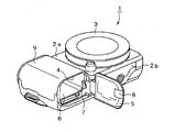
- the battery pack 10 is mounted on a digital still camera 1 that is an electronic device.
- This digital still camera 1 has a camera body 2 having a substantially rectangular shape, and a lens unit 3 in which a plurality of lens groups such as a zoom lens and a condenser lens are incorporated is provided on a front surface 2a.
- the camera body 2 is provided with a release button that is pressed when one of the corners on the upper surface is imaged, and a flash button is provided on the upper surface side of the front surface 2a of the camera body 2.
- a light emitting unit for photographing is provided.
- One side of the camera body 2 in the longitudinal direction is formed to bulge out to be thicker than the other region, and serves as a grip 9.
- a battery storage 6 is provided inside the grip 9.
- a battery insertion port 4 having a substantially rectangular shape for accommodating the battery pack 10 is substantially the same size as the front surface of the battery pack 10 and has the same shape. Further, a battery lid 5 for opening and closing the battery insertion port 4 is provided.
- the camera main body 2 is provided with a battery housing portion 6 continuously from the battery insertion port 4.
- the battery insertion port 4 is provided with a lock member 7 for holding the battery pack 10 attached to the battery storage 6 in the storage position. When the battery pack 10 is mounted in the battery housing portion 6, the lock member 7 engages with a corner portion on the back surface of the battery pack 10 that is biased in the discharge direction by the spring pressure of the connection terminal or the discharge spring. It is prevented from dropping out of the storage unit 6.
- the lock member 7 is rotatably attached in the vicinity of the battery insertion port 4.
- the lock member 7 engages with the corner portion on the back surface of the battery pack 10 in which the lock claw is mounted on the battery storage unit 6 by the tip portion facing the battery insertion port 4 by the turning operation.
- the lock member 7 prevents the battery pack 10 from popping out of the battery insertion port 4 due to the spring pressure of the connection terminal and the spring pressure of the discharge spring from the battery housing 6.
- the battery cover 5 is rotatably attached in the vicinity of the battery insertion port 4 so as to open and close the battery insertion port 4.
- the battery lid 5 is provided with a lid lock portion 8 on the distal end side.
- the lid lock portion 8 is slidably provided on the battery lid 5.
- the lid lock portion 8 is a lock formed at the opening end of the battery insertion port 4 by sliding in the locking direction protruding from the tip of the battery lid 5 with the battery lid 5 closing the battery insertion port 4. Engage with the recess. Thereby, the battery cover 5 locks the battery insertion port 4 in a closed state.
- the battery lid 5 releases the engagement state between the lid lock portion 8 and the lock concave portion by sliding the lid lock portion 8 in the unlocking direction in which the lid lock portion 8 is retracted into the battery lid 5. Thereby, the battery lid 5 can be rotated and the battery insertion opening 4 can be opened.
- the lock member 7 In order to remove the battery pack 10 from the battery housing portion 6, the lock member 7 is rotated and retracted from the battery insertion port 4, and the rear corner portion of the battery pack 10 and the lock member 7 are engaged. What is necessary is just to cancel a state. Thereby, the battery pack 10 is discharged so as to protrude from the battery insertion port 4 by the spring pressure of the connection terminal and the spring pressure of the discharge spring.
- a lithium ion secondary battery is used as the battery pack 10 that is inserted from the battery insertion port 4 and is attached to the battery housing 6 and supplies power to the camera body 2. .
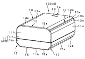
- the battery pack 10 includes a pack body 11 in which a battery cell 10 a of a lithium ion secondary battery is built.
- the pack body 11 is formed in a substantially rectangular parallelepiped shape as a whole, and is formed so that six surfaces are substantially flat.
- the front surface 11 e of the pack body 11 is a terminal surface on which a terminal portion 21 is formed.
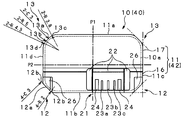
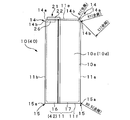
- Both the first and second corner portions 12 and 13 formed by the side surfaces 11c and 11d facing the top surface 11a and the bottom surface 11b of the pack body 11 are formed with chamfered portions.
- the chamfered portions of the first corner portions 12 and 12 formed by the side surfaces 11c and 11d facing the bottom surface 11b of the pack body 11 are both C surfaces 12a.
- the angle is 45 ° and the chamfer dimension is 3 mm.
- both sides of the C surface 12a are R surfaces 12b and 12b, and here have a radius of 2 mm.
- the dimensions of the C surface 12a and the R surface 12b are not limited to this.
- the chamfered portions of the second corner portions 13 and 13 formed by the side surfaces 11c and 11d facing the upper surface 11a of the pack body 11 are substantially R surfaces.
- the second corner portions 13 and 13 are substantially R surfaces 13 a that are inscribed in the same C surface as the C surface 12 a of the chamfered portion of the first corner portions 12 and 12 of the pack body 11.
- the second corner portions 13 and 13 have a middle shape in which the C surface 13a and the first R surface 13b are continuous in the middle.
- the chamfer angle is 45 ° and the chamfer dimension is 3 mm.
- C surface 13a and a first R surface 13b having a radius of 5 mm.
- the C surface 13 a of the second corner portions 13, 13 has the same chamfer as the C surface 12 a of the first corner portion 12. Furthermore, the upper surface 11a side of the C surface 13a is a second R surface 13c so as to be continuous with the upper surface 11a. Here, the radius is 3.8 mm. The bottom surface 11b side of the first R surface 13b is a third R surface 13d so as to be continuous with the bottom surface 11b, and here has a radius of 4.3 mm.
- the dimensions of the C surface 13a and the first to third R surfaces 13b-13d are not limited to this. Further, in the second corner portion 13, the portion of the C surface 13 a is omitted, and the omitted portion is also inscribed in the same C surface as the C surface 12 a of the chamfered portion of the first corner portions 12, 12. R surface 13b may be used.
- the pack body 11 can be reduced in size as a whole by forming chamfered portions in the first and second corner portions 12 and 13 formed by the side surfaces 11c and 11d facing the top surface 11a and the bottom surface 11b.
- the pack body 11 has different shapes for the chamfered portions of the first corner portions 12 and 12 on the bottom surface 11 b side of the pack body 11 and the second corner portions 13 and 13 on the upper surface 11 a side of the pack body 11.
- the pack main body 11 is configured to be able to identify the upper and lower surfaces of the pack main body 11 when the user touches it with the hand, and to prevent erroneous insertion into the battery storage unit 6.
- the shape of the 1st corner part 12 demonstrated above and the shape of the 2nd corner part 13 are replaced, and the shape of the 1st corner part 12 is made into the shape of the 2nd corner part 13, and it is the 2nd corner part.
- the shape of the portion 13 may be the first shape.
- the front side corner portion 14 formed by the front surface 11e of the pack body 11, the upper surface 11a and the bottom surface 11b, and the rear side corner portion 15 formed by the rear surface 11f and the upper surface 11a and the bottom surface 11b are both chamfered portions.
- the back side corner portion 15 formed by the back surface 11f of the pack body 11, the top surface 11a, and the bottom surface 11b is an R surface 15a having a radius of 0.5 mm.
- the front side corner portion 14 formed by the front surface 11e, the upper surface 11a and the bottom surface 11b of the pack body 11 is a C surface 14a having a chamfering angle of 45 ° and a chamfering dimension of 1 mm, and R surfaces 14b each having a radius of 1 mm. ing.
- the pack body 11 has a smaller chamfering of the rear side corner portion 15 than the front side corner portion 14.
- the lock claw of the lock member 7 on the battery storage unit 6 side of the camera body 2 is easily engaged with the back side corner portion 15 of the pack body 11.
- the rear side corner portion 15 can be easily engaged with the lock claw of the lock member 7 on the battery storage portion 6 side, so that the lock member 7 of the battery insertion port 4 can be downsized.
- the pack main body 11 realizes a reduction in size as a whole by forming chamfered portions in the front side corner portion 14 and the back side corner portion 15.
- the front side corner part 14 and the back side corner part 15 are a combination of the C surface, the R surface, and the C surface and the R surface. Any shape may be sufficient.
- the dimension of the front side corner part 14 or the back side corner part 15 is not limited to the above example.
- the corner portion with which the lock member 7 is engaged is the front side corner portion 14
- the chamfering of the front side corner portion 14 is made smaller than that of the rear side corner portion 15, contrary to the above example.
- the pack body 11 that houses the battery cell 10 a is formed by welding and joining halves of pack halves 16, 17 formed by injection molding synthetic resin with an adhesive or the like.
- One pack half 16 is matted.
- the pack main body 11 is configured so that the upper and lower sides of the pack main body 11 can be identified by tactile sensation or visual sense even by the matte processing of the pack half body 16.
- an insertion direction display portion 18 is formed on the upper surface 11a of the pack body 11 on the front surface 11e side on which the terminal portion is provided by engraving or printing a triangle mark or the like.
- a terminal part 21 is formed on the front surface 11e of the pack body 11.
- the terminal portion 21 is provided on the front surface 11e so as to protrude at a position deviated to one side with respect to the center line P1 in the width direction and the center line P2 in the height direction.
- the terminal portion 21 opens the bottom surface 11b side of the pack body 11 and surrounds the three sides with the rising wall 22, and inside the rising wall 22, the minus terminal 23a and the control are sequentially formed from the center line P1 side in the width direction.
- a terminal 23b and a plus terminal 23c are provided.
- terminals 23a-23c are formed so that the contact springs are exposed from inside the slits in the height direction to protect the contact springs.
- the negative connection terminal, the control connection terminal, and the positive connection terminal on the bottom surface of the battery housing 6 enter the slits of the negative terminal 23a, the control terminal 23b, and the positive terminal 23c, and are electrically connected to the contact springs in the slits. Connected.
- Guide grooves 24 and 24 are formed outside the negative terminal 23a and the positive terminal 23c.
- the guide grooves 24, 24 are formed wider than the slits of the terminal portions 23a-23c.
- the number of terminals of the terminal portion 21 is not limited to this, and may be four or more by providing a reserve terminal and other purpose terminals. Further, only the minus terminal and the plus terminal may be used.
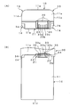
- FIG. 7A shows a battery pack 100 shown as a reference example
- FIG. 7B shows a battery pack 10 according to the present embodiment.
- the terminal surface of the pack body 101 is flat.
- a space having a depth D1 is required in the pack body 101 in order to provide the terminal portion 111 for receiving the connection terminal 6b provided protruding from the bottom surface of the battery housing portion 6.
- the both sides of the terminal portion 111 are likely to be empty spaces 112.
- the terminal portion 21 is protruded so as to bite from the front surface 11e for providing the terminal portion 21 in the pack main body 11.
- the space 21a can be made shallow to a depth D2. That is, the pack body 11 is reduced in size by the amount by which the terminal portion 21 is protruded (D3).
- the pack body 11 can reduce the empty space 21b on both sides of the terminal portion 21 and can realize downsizing accordingly.
- the distal end surface 21c of the terminal portion 21 can be made closer to the bottom surface of the battery storage portion 6 of the camera body 2 (C1> C2 in FIG. 7).
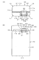
- FIG. 8A shows the battery pack 10 according to the present embodiment.
- the lower half indicated by the solid line in FIG. 8A indicates the lower half from the center line P2 in the height direction of FIG. 5, and the upper half indicated by the dotted line indicates a state in which the lower half is rotated 180 degrees symmetrically.
- FIG. 8B illustrates a reference example, in which the terminal portion 121 is provided at a position that is biased to one side in the thickness direction at the center in the width direction.
- the lower half shown by the solid line in FIG. 8B shows the lower half from the center line P2 in the height direction of FIG. 5, and the upper half shown by the dotted line shows a state in which the lower half is rotated 180 degrees symmetrically.
- the battery pack 10 is inserted upside down at the positions of the terminal portions 21 and 121 (portions indicated by dotted lines) in a state where the lower half is rotated 180 degrees symmetrically with respect to the lower half.
- the positions of the terminal portions 21 and 121 are as follows.
- the terminal portion 21 at a position deviated to one side with respect to the center line in the width direction and the thickness direction of the front surface 11e is when the terminal portion 21 is positioned symmetrically with respect to the normal position.
- the position does not interfere with the connection terminal 6b provided to protrude from the bottom surface of the battery storage unit 6.
- the area where the discharge spring 6a provided on the bottom surface of the battery housing portion 6 of the camera main body 2 contacts can be enlarged.
- a coil spring having a radius of 5 mm can be used.
- the front surface 11e of the battery pack 10 is provided with a terminal portion 121 at a position biased to one side in the thickness direction at the center in the width direction.
- the terminal portion 121 is positioned point-symmetrically with respect to the normal position, there is a possibility that the terminal portion 121 may interfere with the connection terminal 6 b provided to protrude from the bottom surface of the battery housing portion 6.
- the area where the discharge spring 6a provided on the bottom surface of the battery housing portion 6 of the camera body 2 contacts the front surface 11e of the pack body 11 is smaller than that of FIG. 8A. turn into.
- only a coil spring having a radius of 4 mm can be used.
- the distance between the control terminal 23b at the center in the width direction of the terminal portion 21 and the center of the circular area where the discharge spring 6a contacts is 12.3 mm.
- the distance between the control terminal 23b at the center in the width direction of the terminal portion 121 and the center of the circular area where the discharge spring 6a abuts is only 11.35 mm. Can not.
- the front surface 11e of the pack body 11 is formed with recesses 26 and 26 straddling the opposite side surfaces 11c and 11d and the bottom surface 11b.
- the recesses 26 and 26 become recesses with which the positioning protrusions on the charging device are engaged when mounted on the charging device.
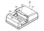
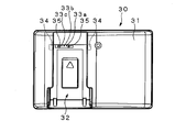
- the charging device 30 includes a charging circuit in the device main body 31 and a battery mounting portion 32 to which the battery pack 10 is mounted.
- the battery mounting portion 32 is a recess having substantially the same size as the bottom surface 11 b of the pack body 11.
- the battery mounting portion 32 is provided with a negative charging terminal 33a, a control charging terminal 33b, and a positive charging terminal 33c, which serve as the charging terminal portion 33, at one end where the front surface 11e of the pack body 11 is abutted.
- the battery mounting portion 32 is also formed with guide protrusions 35 and 35 that engage with the guide grooves 24 and 24.
- positioning protrusions 34 and 34 that engage with the recesses 26 and 26 of the pack body 11 are formed on both sides of the surface against which the front surface 11e of the pack body 11 is abutted.
- the battery pack 10 is mounted on the battery mounting portion 32 with the front surface 11e of the pack body 11 as an insertion end. Then, the positioning protrusions 34 and 34 are positioned by engaging with the recesses 26 and 26, and the terminal portion 21 and the charging terminal portion 33 of the battery pack 10 are electrically connected to start charging. Will be.
- the DC plate 40 As a device for supplying power to the digital still camera 1, there is a DC plate 40 as shown in FIG. 11 in addition to the battery pack 10 stored in the battery storage unit 6.
- the DC plate 40 is housed in the battery housing 6 of the digital still camera 1 instead of the battery pack 10 and is connected to an AC adapter that converts household AC power into DC power.
- the DC plate 40 is stored in the battery storage unit 6 to supply DC power to the digital still camera 1. Since the DC plate 40 is housed in the battery housing 6, the plate body 42 is the same size as the battery pack 10 and has the same shape except for the shape on the back side where the cord 41 is led out. Yes.
- the same part as the battery pack 10 attaches
- the DC plate 40 has the same shape on the side of insertion into the battery pack 10 and the battery storage unit 6. For this reason, the DC plate 40 may be erroneously attached to the battery attachment portion 32 of the charging device 30. Therefore, the DC plate 40 is not formed with the concave portions 26 and 26 straddling the side surfaces 11c and 11d and the bottom surface 11b on the front surface side.
- the front surface 11e of the pack body 11 of the battery pack 10 is formed with recesses 26 and 26 straddling the opposite side surfaces 11c and 11d and the bottom surface 11b.
- positioning protrusions 34, 34 that engage with the recesses 26, 26 are formed on the battery mounting portion 32 of the charging device 30. Therefore, when the battery pack 10 is mounted on the battery mounting portion 32 of the charging device 30, the positioning protrusions 34 and 34 of the battery mounting portion 32 engage with the recesses 26 and 26. As a result, the battery pack 10 is mounted on the battery mounting portion 32 of the charging device 30.
- the battery pack 10 configured as described above has a front surface 11e of the pack body 11 and a battery housing portion 6 of the camera body 2. It becomes the insertion end to the battery insertion port 4 that is continuous.
- the insertion direction and the vertical direction into the battery insertion port 4 are identified by the following configuration of the pack body 11 in addition to the insertion direction display portion 18 formed on the upper surface 11 a of the pack body 11. Can do.
- the pack body 11 has different shapes for the chamfered portions of the first corner portions 12 and 12 on the bottom surface 11b side and the second corner portions 13 and 13 on the upper surface 11a side. Thereby, the pack main body 11 can identify the upper and lower surfaces of the pack main body 11 when the user touches it with a hand, and can prevent erroneous insertion into the battery storage unit 6.
- the pack body 11 has one pack half 16 matte and can be distinguished from the other pack half 17 by touch and visual sense, thereby preventing erroneous insertion into the battery housing 6. it can.
- the insertion direction of the battery pack 10 can be identified by the chamfering of the back side corner portion 15 being smaller than the front side corner portion 14 of the pack body 11.
- the battery pack 10 can identify the orientation when stored in the battery storage unit 6 by visual or tactile sense, and prevent erroneous insertion.
- the negative connection terminal, the control connection terminal, and the positive connection on the bottom surface of the battery storage unit 6 are inserted into the slits of the negative terminal 23a, the control terminal 23b, and the positive terminal 23c. Terminal enters.
- the minus connection terminal, the control connection terminal, and the plus connection terminal of the battery storage unit 6 are electrically connected to the contact springs in the slits.
- positioning protrusions 34, 34 that engage with the recesses 26, 26 on the front surface 11e of the pack body 11 are not provided on the bottom surface of the battery housing 6 of the digital still camera 1. This is because the DC plate 40 in which the concave portions 26, 26 are not provided on the front surface 11 e can be stored in the battery storage unit 6.
- the shape of the second corner portions 13 and 13 on the upper surface 11a side of the pack body 11 is in the same C surface as the C surface 12a of the chamfered portion of the first corner portions 12 and 12 on the bottom surface 11b side of the pack body 11. It is a substantially R surface in contact. Therefore, the battery pack 10 can be stored in the battery storage unit 6 even when stored in the battery storage unit 6 upside down. Further, the pack body 11 can prevent the battery pack 10 from being forcibly inserted and damaged on the inner wall or the like of the battery housing 6.
- the terminal portion 21 is in a position deviated to one side with respect to the center line in the width direction and the thickness direction of the front surface 11e, and therefore contacts the connection terminal 6b provided to protrude from the bottom surface of the battery storage portion 6. None will happen. Thereby, even when the battery pack 10 is erroneously inserted, the terminal portion 21 and the connection terminal 6b can be prevented from being damaged due to interference or collision with each other.
- the lock member 7 that is rotatably attached to the back side corner portion 15 of the pack body 11 in the vicinity of the battery insertion port 4 is rotated. As a result, the lock claw of the lock member 7 is engaged. Thereby, the battery pack 10 is prevented from jumping out from the battery insertion port 4 due to the spring pressure of the connection terminal and the spring pressure of the discharge spring 6a from the battery storage unit 6.
- the pack body 11 has a chamfered portion of the back side corner portion 15 smaller than that of the front side corner portion 14, so that the lock claw of the lock member 7 can be easily engaged. Therefore, the pack body 11 can be reliably locked by the lock member 7.
- the battery lid 5 that is rotatably attached in the vicinity of the battery insertion slot 4 closes the battery insertion slot 4 and is locked by the lid lock portion 8.
- the battery pack 10 is reliably stored in the battery storage unit 6 of the digital still camera 1.
- the lock of the cover lock unit 8 is released, the battery cover 5 is opened, and the lock by the lock member 7 is released. Thereby, the battery pack 10 is discharged so as to protrude from the battery insertion port 4 by the spring pressure of the connection terminal and the spring pressure of the discharge spring.
- the first and second side surfaces 11c and 11d formed by the upper surface 11a and the bottom surface 11b of the pack body 11 are opposed to each other.
- the pack body 11 has different shapes for the chamfered portions of the first corner portions 12, 12 on the bottom surface 11 b side of the pack body 11 and the second corner portions 13, 13 on the upper surface 11 a side of the pack body 11. .
- the pack main body 11 can identify the upper and lower surfaces of the pack main body 11 when the user touches it with a hand, and can prevent erroneous insertion into the battery storage unit 6.
- the pack body 11 has a chamfering of the back side corner portion 15 smaller than that of the front side corner portion 14. Accordingly, the pack body 11 can easily engage the lock claw of the lock member 7 on the battery storage unit 6 side of the camera body 2 with the rear side corner portion 15. In addition, the rear side corner portion 15 can be easily engaged with the lock claw of the lock member 7 on the battery storage portion 6 side, so that the lock member 7 of the battery insertion port 4 can be downsized. Furthermore, the pack main body 11 can implement
- the space 21a that bites in from the front surface 11e for providing the terminal portion 21 in the pack body 11 by the amount by which the terminal portion 21 protrudes Shallow depth D2. That is, the pack body 11 can be reduced in size by the amount by which the terminal portion 21 protrudes (D3). As a result, the pack body 11 can reduce the empty space 21b on both sides of the terminal portion 21 and can realize downsizing accordingly. Further, the distal end surface 21c of the terminal portion 21 can be made closer to the bottom surface of the battery storage portion 6 of the camera body 2 (C1> C2 in FIG. 7).
- FIG. 8A when the terminal portion 21 is in a position deviated to one side with respect to the center line in the width direction and the thickness direction of the front surface 11e, the terminal portion 21 is positioned symmetrically with respect to the normal position. Even in this case, the position does not interfere with the connection terminal 6 b provided to protrude from the bottom surface of the battery housing 6. Therefore, even when the battery pack 10 is inserted upside down, it is possible to prevent the battery pack 10 from interfering with the connection terminal 6b provided to protrude from the bottom surface of the battery storage unit 6. Further, in the example of FIG. 8A, in the front surface 11e of the pack main body 11, the area where the discharge spring 6a provided on the bottom surface of the battery housing portion 6 of the camera main body 2 contacts can be enlarged.
- the battery pack 10 is provided with the recesses 26 and 26 on the front surface 11 e of the pack body 11, and the DC plate 40 is provided with the recesses 26 and 26 on the front surface 11 e of the plate body 42.
- the battery mounting part 32 of the charging device 30 positioning protrusions 34, 34 are provided. Therefore, only the battery pack 10 having the recesses 26, 26 can be mounted on the battery mounting portion 32 of the charging device 30, and it is possible to prevent the DC plate 40 from being erroneously mounted on the battery mounting portion 32.
- the present invention can also be applied to the DC plate 40 as described above.
- the DC plate 40 is housed in the battery housing 6 of the digital still camera 1 in place of the battery pack 10 and is connected to an AC adapter that converts household AC power into DC power. Is done.
- the DC plate 40 is stored in the battery storage unit 6 to supply DC power to the digital still camera 1. Since the DC plate 40 is stored in the battery storage unit 6, the DC plate 40 has the same size as the battery pack 10 except for the shape on the back side where the cord 41 is led out. Yes.
- the DC plate 40 is also reduced in overall size by forming chamfered portions in the first and second corner portions 12 and 13 formed by the side surfaces 11c and 11d facing the upper surface 11a and the bottom surface 11b of the plate body 42. It aims at realization. Further, the plate main body 42 has different shapes for the chamfered portions of the first corner portions 12 and 12 on the bottom surface 11b side and the second corner portions 13 and 13 on the upper surface 11a side. Thus, the plate main body 42 can identify the upper and lower surfaces of the plate main body 42 when touched by the user, and can prevent erroneous insertion into the battery housing portion 6 (see FIGS. 3 to 6). ).
- the plate main body 42 is smaller in the chamfering of the rear side corner portion 15 than the front side corner portion 14. Thereby, the lock claw of the lock member 7 on the battery storage unit 6 side of the camera main body 2 is easily engaged with the rear side corner portion 15 of the plate main body 42. In addition, the rear side corner portion 15 can be easily engaged with the lock claw of the lock member 7 on the battery storage portion 6 side, so that the lock member 7 of the battery insertion port 4 can be downsized. Further, the plate main body 42 can be reduced in size as a whole by forming chamfered portions in the front side corner portion 14 and the rear side corner portion 15 (see FIGS. 3 to 6).
- the space 21a that cuts in from the front surface 11e for providing the terminal portion 21 in the plate main body 42 can be made shallower and the depth D2 by the amount of the protruding terminal portion 21. That is, the plate body 42 can be reduced in size by the amount by which the terminal portion 21 protrudes (D3). Thereby, the plate main body 42 can make the empty space 21b on both sides of the terminal portion 21 small, and can realize miniaturization correspondingly.
- the front end surface 21c of the terminal portion 21 can be made closer to the bottom surface of the battery housing portion 6 of the camera body 2 (C1> C2 in FIG. 7) (see FIG. 7).
- FIG. 8A when the terminal portion 21 is in a position deviated to one side with respect to the center line in the width direction and the thickness direction of the front surface 11e, the terminal portion 21 is positioned symmetrically with respect to the normal position. Even in this case, the position does not interfere with the connection terminal 6 b provided to protrude from the bottom surface of the battery housing 6. Therefore, even when the DC plate 40 is inserted upside down, it can be prevented from interfering with the connection terminal 6b provided protruding from the bottom surface of the battery housing 6 (see FIG. 8). Further, in the example of FIG. 8A, in the front surface 11e of the plate main body 42, an area where the discharge spring 6a provided on the bottom surface of the battery housing portion 6 of the camera main body 2 contacts can be enlarged.
- FIG. 14 shows that the chamfered portions of the first and second corner portions 12 and 13 are both C-shaped.
- the first and second corner portions 12 and 13 both form R surfaces 12p and 13p on both sides of the C surfaces 12o and 13o.
- the chamfered portions of the first and second corner portions 12 and 13 are both formed into an R-surface shape.
- the first and second corner portions 12 and 13 together form R surfaces 12x and 13x.
- the digital still camera 1 using the battery pack 10 and the DC plate 40 has been described above as an example.
- electronic devices using the battery pack 10 and the DC plate 40 are as follows. There is something like this.
- the electronic device may be an imaging device such as a digital video camera.
- PDA Personal Digital Assistant (Personal Data Assistance)
- mobile phone laptop computer, or the like.
- the battery cell is not limited to a lithium ion secondary battery, and may be a nickel hydride secondary battery or the like.
Landscapes
- Chemical & Material Sciences (AREA)
- Chemical Kinetics & Catalysis (AREA)
- Electrochemistry (AREA)
- General Chemical & Material Sciences (AREA)
- Engineering & Computer Science (AREA)
- Materials Engineering (AREA)
- Manufacturing & Machinery (AREA)
- Battery Mounting, Suspending (AREA)
- Studio Devices (AREA)
- Sealing Battery Cases Or Jackets (AREA)
- Connection Of Batteries Or Terminals (AREA)
Priority Applications (11)
| Application Number | Priority Date | Filing Date | Title |
|---|---|---|---|
| BRPI1106067A BRPI1106067A2 (pt) | 2010-03-29 | 2011-02-21 | fonte de alimentação |
| EP11762409.8A EP2426757B1 (en) | 2010-03-29 | 2011-02-21 | Electric source supply device |
| KR1020177002704A KR101821099B1 (ko) | 2010-03-29 | 2011-02-21 | 배터리 및 촬상 장치 |
| CN201180002171.2A CN102439758B (zh) | 2010-03-29 | 2011-02-21 | 电源 |
| KR1020117025803A KR101757941B1 (ko) | 2010-03-29 | 2011-02-21 | 배터리 |
| US13/321,089 US8828601B2 (en) | 2010-03-29 | 2011-02-21 | Battery pack |
| RU2011147463/07A RU2572602C2 (ru) | 2010-03-29 | 2011-02-21 | Источник питания |
| EP13198818.0A EP2712007B1 (en) | 2010-03-29 | 2011-02-21 | Power supply |
| US14/333,360 US9716254B2 (en) | 2010-03-29 | 2014-07-16 | Battery pack |
| US15/628,385 US10217972B2 (en) | 2010-03-29 | 2017-06-20 | Battery pack |
| US16/239,355 US11101512B2 (en) | 2010-03-29 | 2019-01-03 | Battery pack |
Applications Claiming Priority (2)
| Application Number | Priority Date | Filing Date | Title |
|---|---|---|---|
| JP2010002063U JP3160044U (ja) | 2010-03-29 | 2010-03-29 | 電源供給装置 |
| JP2010-002063U | 2010-03-29 |
Related Child Applications (2)
| Application Number | Title | Priority Date | Filing Date |
|---|---|---|---|
| US13/321,089 A-371-Of-International US8828601B2 (en) | 2010-03-29 | 2011-02-21 | Battery pack |
| US14/333,360 Continuation US9716254B2 (en) | 2010-03-29 | 2014-07-16 | Battery pack |
Publications (1)
| Publication Number | Publication Date |
|---|---|
| WO2011122169A1 true WO2011122169A1 (ja) | 2011-10-06 |
Family
ID=44711902
Family Applications (1)
| Application Number | Title | Priority Date | Filing Date |
|---|---|---|---|
| PCT/JP2011/053736 Ceased WO2011122169A1 (ja) | 2010-03-29 | 2011-02-21 | 電源供給装置 |
Country Status (10)
| Country | Link |
|---|---|
| US (4) | US8828601B2 (pt) |
| EP (4) | EP2579355B1 (pt) |
| JP (1) | JP3160044U (pt) |
| KR (2) | KR101821099B1 (pt) |
| CN (5) | CN104900838B (pt) |
| BR (1) | BRPI1106067A2 (pt) |
| DE (1) | DE202011110071U1 (pt) |
| RU (1) | RU2572602C2 (pt) |
| TW (1) | TWI434450B (pt) |
| WO (1) | WO2011122169A1 (pt) |
Cited By (1)
| Publication number | Priority date | Publication date | Assignee | Title |
|---|---|---|---|---|
| JP2021125106A (ja) * | 2020-02-07 | 2021-08-30 | カシオ計算機株式会社 | 情報端末 |
Families Citing this family (39)
| Publication number | Priority date | Publication date | Assignee | Title |
|---|---|---|---|---|
| US6895756B2 (en) | 2002-09-13 | 2005-05-24 | The Boeing Company | Compact swirl augmented afterburners for gas turbine engines |
| JP5742096B2 (ja) | 2009-12-29 | 2015-07-01 | ソニー株式会社 | バッテリパック |
| JP3160044U (ja) | 2010-03-29 | 2010-06-10 | ソニー株式会社 | 電源供給装置 |
| DE102013202062A1 (de) * | 2013-02-08 | 2014-08-14 | Robert Bosch Gmbh | Akkumulatorzelle und Akkumulatormodul |
| JP6986236B2 (ja) * | 2014-03-24 | 2021-12-22 | 大日本印刷株式会社 | プラスチックボトルおよびプリフォーム |
| CN204302638U (zh) * | 2014-10-24 | 2015-04-29 | 乐清市创意影视器材有限公司 | 一种相机机顶闪光灯 |
| USD830446S1 (en) | 2015-12-15 | 2018-10-09 | Gopro, Inc. | Multi-lens camera |
| USD791695S1 (en) | 2017-01-20 | 2017-07-11 | Gopro, Inc. | Battery |
| JP6191795B1 (ja) | 2017-02-10 | 2017-09-06 | ソニー株式会社 | バッテリー及び接続機器 |
| JP6191796B1 (ja) | 2017-02-10 | 2017-09-06 | ソニー株式会社 | バッテリー及び接続機器 |
| JP6961985B2 (ja) * | 2017-02-10 | 2021-11-05 | ソニーグループ株式会社 | バッテリー及び接続機器 |
| WO2018230524A1 (ja) * | 2017-06-16 | 2018-12-20 | 株式会社Gsユアサ | 蓄電装置 |
| CN107645879A (zh) * | 2017-08-30 | 2018-01-30 | 广东风华高新科技股份有限公司 | 一种陶瓷电子部件及其制备方法 |
| USD861592S1 (en) | 2017-09-28 | 2019-10-01 | Gopro, Inc. | Battery |
| USD940066S1 (en) | 2017-09-28 | 2022-01-04 | Gopro, Inc. | Battery |
| USD890835S1 (en) | 2017-12-28 | 2020-07-21 | Gopro, Inc. | Camera |
| USD907680S1 (en) | 2018-08-31 | 2021-01-12 | Gopro, Inc. | Camera |
| USD907101S1 (en) | 2019-06-11 | 2021-01-05 | Gopro, Inc. | Camera |
| USD903740S1 (en) | 2018-09-14 | 2020-12-01 | Gopro, Inc. | Camera |
| CN111067423B (zh) * | 2018-10-19 | 2022-07-19 | 德国福维克控股公司 | 可更换的蓄电池 |
| USD920419S1 (en) | 2019-09-17 | 2021-05-25 | Gopro, Inc. | Camera |
| USD1029745S1 (en) | 2019-09-13 | 2024-06-04 | Gopro, Inc. | Camera battery |
| CN217470540U (zh) | 2019-09-18 | 2022-09-20 | 高途乐公司 | 图像捕获设备和用于图像捕获设备的门组件 |
| US12066748B2 (en) | 2019-09-18 | 2024-08-20 | Gopro, Inc. | Door assemblies for image capture devices |
| JP7103389B2 (ja) | 2019-12-18 | 2022-07-20 | カシオ計算機株式会社 | リチウム電池モジュール及び電子機器 |
| CN112993450B (zh) * | 2019-12-18 | 2023-06-09 | 卡西欧计算机株式会社 | 锂电池、锂电池模块以及电子设备 |
| DE102020104783A1 (de) | 2020-02-24 | 2021-08-26 | Volocopter Gmbh | Batteriehaltevorrichtung, Batteriesystem, Fluggerät und Verfahren zum Wechseln einer Batterie für ein Fluggerät |
| WO2022000417A1 (en) | 2020-07-02 | 2022-01-06 | Gopro, Inc. | Removable battery door assemblies for image capture devices |
| USD1029746S1 (en) | 2020-07-31 | 2024-06-04 | Gopro, Inc. | Battery |
| USD1050227S1 (en) | 2020-08-14 | 2024-11-05 | Gopro, Inc. | Camera door |
| USD946074S1 (en) | 2020-08-14 | 2022-03-15 | Gopro, Inc. | Camera |
| USD1066462S1 (en) | 2021-02-12 | 2025-03-11 | Gopro, Inc. | Camera door |
| USD1061682S1 (en) | 2022-08-04 | 2025-02-11 | Gopro, Inc. | Camera door |
| USD1107775S1 (en) | 2022-08-04 | 2025-12-30 | Gopro, Inc. | Camera |
| US12321084B2 (en) | 2022-08-12 | 2025-06-03 | Gopro, Inc. | Interconnect mechanism for image capture device |
| USD1111083S1 (en) | 2024-04-03 | 2026-02-03 | Gopro, Inc. | Camera door |
| USD1101016S1 (en) | 2024-04-03 | 2025-11-04 | Gopro, Inc. | Camera |
| USD1110393S1 (en) | 2024-04-26 | 2026-01-27 | Gopro, Inc. | Camera door |
| USD1118735S1 (en) | 2024-05-22 | 2026-03-17 | Gopro, Inc. | Camera |
Citations (6)
| Publication number | Priority date | Publication date | Assignee | Title |
|---|---|---|---|---|
| JP2000058015A (ja) * | 1998-08-07 | 2000-02-25 | Mitsubishi Cable Ind Ltd | 電池パック |
| JP2003036828A (ja) | 2001-07-24 | 2003-02-07 | Sony Corp | 本体側機器に対する装着部品の誤装着防止方法およびこれに用いられる装着部品 |
| JP2004327447A (ja) * | 2001-07-25 | 2004-11-18 | Sony Corp | バッテリパック及びバッテリ装着装置 |
| JP2005190956A (ja) * | 2003-12-26 | 2005-07-14 | Sanyo Electric Co Ltd | 薄型バッテリーパック |
| JP2009170236A (ja) * | 2008-01-16 | 2009-07-30 | Canon Inc | バッテリー装置及び撮像装置 |
| JP2009205844A (ja) * | 2008-02-26 | 2009-09-10 | Panasonic Corp | 電池パック |
Family Cites Families (38)
| Publication number | Priority date | Publication date | Assignee | Title |
|---|---|---|---|---|
| JPH0813169B2 (ja) | 1990-12-01 | 1996-02-07 | 三洋電機株式会社 | 充電装置及び充電方法 |
| CA2408978C (en) * | 1992-05-29 | 2004-12-28 | Sony Corporation | Battery cartridge having hollow electrodes and a recess for detecting misuse and/or recessed terminals |
| JP3416962B2 (ja) | 1992-09-18 | 2003-06-16 | ソニー株式会社 | バッテリーパック |
| JP2711223B2 (ja) | 1994-07-29 | 1998-02-10 | インターナショナル・ビジネス・マシーンズ・コーポレイション | バッテリパック及びその接続構造 |
| JPH09271144A (ja) | 1996-01-29 | 1997-10-14 | Sony Corp | 電源識別方法、乾電池パツク、電子機器 |
| JP3490590B2 (ja) | 1997-05-29 | 2004-01-26 | 富士通株式会社 | 携帯装置のバッテリロック機構 |
| US6051336A (en) * | 1998-01-19 | 2000-04-18 | Johnson Controls Technology | Battery case for thin metal film cells |
| US6127063A (en) | 1998-01-26 | 2000-10-03 | Physio-Control Manufacturing Corporation | Intelligent battery and well interface |
| US6261715B1 (en) | 1998-03-12 | 2001-07-17 | International Business Machines Corp. | Battery attaching mechanism for portable computers |
| USD535253S1 (en) | 1998-06-17 | 2007-01-16 | Black & Decker Inc. | Battery pack terminal and housing |
| US6057608A (en) | 1998-08-13 | 2000-05-02 | Black & Decker Inc. | Cordless power tool system |
| JP2000090961A (ja) | 1998-09-17 | 2000-03-31 | Mitsubishi Cable Ind Ltd | 角型電池及び電池パック |
| FR2785952B1 (fr) * | 1998-11-12 | 2001-04-06 | Alain Husson | Attache rapide pour fixer un outil a l'extremite du bras d'un chargeur ou analogue |
| TW395568U (en) | 1998-12-28 | 2000-06-21 | Hon Hai Prec Ind Co Ltd | Battery connector |
| JP4110656B2 (ja) | 1999-02-17 | 2008-07-02 | ソニー株式会社 | バッテリーパック、バッテリー装着装置、電力供給装置及び電子機器 |
| USD437579S1 (en) * | 1999-03-12 | 2001-02-13 | Eveready Battery Company, Inc. | Battery pack casing |
| US6228526B1 (en) * | 1999-05-14 | 2001-05-08 | Rosslare Enterprises, Ltd. | Battery pack having durable terminals |
| USD447122S1 (en) | 2000-05-30 | 2001-08-28 | J.S.T. Mfg. Co., Ltd. | Housing for an electrical connector |
| JP2002110287A (ja) | 2000-09-14 | 2002-04-12 | Internatl Business Mach Corp <Ibm> | バッテリーコネクタ構造及びバッテリーパック |
| JP3643792B2 (ja) | 2001-06-29 | 2005-04-27 | 三洋電機株式会社 | パック電池とその製造方法 |
| US6677078B2 (en) | 2001-06-29 | 2004-01-13 | The Gillette Company | Battery cartridge |
| KR100919332B1 (ko) | 2001-07-24 | 2009-09-25 | 소니 가부시끼 가이샤 | 배터리 장치 |
| US6729413B2 (en) | 2001-08-24 | 2004-05-04 | Black & Decker Inc. | Power tool with battery pack ejector |
| NL1019047C2 (nl) | 2001-09-26 | 2003-04-02 | Univ Eindhoven Tech | Werkwijze en stelsel voor het via een multi-modus optische vezel overdragen van microgolfsignalen. |
| JP3678188B2 (ja) * | 2001-10-09 | 2005-08-03 | ソニー株式会社 | バッテリパック充電装置 |
| USD473192S1 (en) | 2002-02-14 | 2003-04-15 | Mitsumi Electric Co., Ltd. | Electric connector |
| US7066970B2 (en) * | 2003-05-09 | 2006-06-27 | The Gillette Company | Electrochemical cells |
| JP4123516B2 (ja) * | 2003-12-26 | 2008-07-23 | ソニー株式会社 | バッテリー装置 |
| EP1603246B1 (en) * | 2004-06-02 | 2007-03-21 | Research In Motion Limited | Slim line battery pack |
| JP4622502B2 (ja) * | 2004-12-20 | 2011-02-02 | ソニー株式会社 | バッテリー |
| JP4639818B2 (ja) * | 2005-01-21 | 2011-02-23 | ソニー株式会社 | 電池パック |
| US7722982B2 (en) * | 2005-05-05 | 2010-05-25 | Motorola, Inc. | Battery pack having non-orthogonal coupling slots |
| EP2919295B1 (en) * | 2005-10-31 | 2018-08-29 | Black & Decker, Inc. | Method of arranging the components of a battery pack |
| JP4725317B2 (ja) * | 2005-12-26 | 2011-07-13 | ソニー株式会社 | 電子機器 |
| JP4245017B2 (ja) | 2006-08-28 | 2009-03-25 | ソニー株式会社 | バッテリー装置、電子機器及びバッテリーシステム |
| RU76169U1 (ru) * | 2008-04-04 | 2008-09-10 | Общество с ограниченной ответственностью "Национальная инновационная компания "Новые энергетические проекты" (ООО "Национальная инновационная компания "НЭП") | Корпус экспериментальной аккумуляторной батареи |
| JP5742096B2 (ja) | 2009-12-29 | 2015-07-01 | ソニー株式会社 | バッテリパック |
| JP3160044U (ja) * | 2010-03-29 | 2010-06-10 | ソニー株式会社 | 電源供給装置 |
-
2010
- 2010-03-29 JP JP2010002063U patent/JP3160044U/ja not_active Expired - Lifetime
-
2011
- 2011-02-21 CN CN201510191782.6A patent/CN104900838B/zh active Active
- 2011-02-21 EP EP13150047.2A patent/EP2579355B1/en active Active
- 2011-02-21 BR BRPI1106067A patent/BRPI1106067A2/pt active Search and Examination
- 2011-02-21 EP EP11762409.8A patent/EP2426757B1/en active Active
- 2011-02-21 KR KR1020177002704A patent/KR101821099B1/ko active Active
- 2011-02-21 RU RU2011147463/07A patent/RU2572602C2/ru active
- 2011-02-21 CN CN201510193999.0A patent/CN104900827B/zh active Active
- 2011-02-21 CN CN201510192350.7A patent/CN104900839B/zh active Active
- 2011-02-21 WO PCT/JP2011/053736 patent/WO2011122169A1/ja not_active Ceased
- 2011-02-21 KR KR1020117025803A patent/KR101757941B1/ko active Active
- 2011-02-21 CN CN201180002171.2A patent/CN102439758B/zh active Active
- 2011-02-21 EP EP13198818.0A patent/EP2712007B1/en active Active
- 2011-02-21 CN CN201510191280.3A patent/CN104900818A/zh active Pending
- 2011-02-21 DE DE202011110071U patent/DE202011110071U1/de not_active Expired - Lifetime
- 2011-02-21 US US13/321,089 patent/US8828601B2/en active Active
- 2011-02-21 EP EP13180697.8A patent/EP2665108B1/en active Active
- 2011-03-11 TW TW100108301A patent/TWI434450B/zh active
-
2014
- 2014-07-16 US US14/333,360 patent/US9716254B2/en active Active
-
2017
- 2017-06-20 US US15/628,385 patent/US10217972B2/en active Active
-
2019
- 2019-01-03 US US16/239,355 patent/US11101512B2/en active Active
Patent Citations (6)
| Publication number | Priority date | Publication date | Assignee | Title |
|---|---|---|---|---|
| JP2000058015A (ja) * | 1998-08-07 | 2000-02-25 | Mitsubishi Cable Ind Ltd | 電池パック |
| JP2003036828A (ja) | 2001-07-24 | 2003-02-07 | Sony Corp | 本体側機器に対する装着部品の誤装着防止方法およびこれに用いられる装着部品 |
| JP2004327447A (ja) * | 2001-07-25 | 2004-11-18 | Sony Corp | バッテリパック及びバッテリ装着装置 |
| JP2005190956A (ja) * | 2003-12-26 | 2005-07-14 | Sanyo Electric Co Ltd | 薄型バッテリーパック |
| JP2009170236A (ja) * | 2008-01-16 | 2009-07-30 | Canon Inc | バッテリー装置及び撮像装置 |
| JP2009205844A (ja) * | 2008-02-26 | 2009-09-10 | Panasonic Corp | 電池パック |
Non-Patent Citations (1)
| Title |
|---|
| See also references of EP2426757A4 |
Cited By (1)
| Publication number | Priority date | Publication date | Assignee | Title |
|---|---|---|---|---|
| JP2021125106A (ja) * | 2020-02-07 | 2021-08-30 | カシオ計算機株式会社 | 情報端末 |
Also Published As
Similar Documents
| Publication | Publication Date | Title |
|---|---|---|
| JP3160044U (ja) | 電源供給装置 | |
| CN101241979B (zh) | 电池设备 | |
| JPH08171890A (ja) | 電源ユニットの誤装着防止装置 | |
| JPH07335186A (ja) | バッテリ装置及びこのバッテリ装置が装着される電子機器 | |
| WO2018146860A1 (ja) | バッテリー及び接続機器 | |
| TWI309482B (pt) | ||
| JP4797016B2 (ja) | 携帯通信端末 | |
| CN1806378B (zh) | 直流适配器及使用该直流适配器的电子设备 | |
| TWI343687B (pt) | ||
| CN100435385C (zh) | 电池 | |
| JP4001144B2 (ja) | Dcアダプタ及びこれを用いた電子機器 | |
| JP2019165028A (ja) | バッテリー及び接続機器 | |
| HK1091958B (en) | Dc adaptor and electronic apparatus using the same | |
| HK1091958A1 (en) | Dc adaptor and electronic apparatus using the same | |
| JP2013143228A (ja) | 電池パック誤挿入時の端子破損防止構造、電子機器および電池パック |
Legal Events
| Date | Code | Title | Description |
|---|---|---|---|
| WWE | Wipo information: entry into national phase |
Ref document number: 201180002171.2 Country of ref document: CN |
|
| ENP | Entry into the national phase |
Ref document number: 20117025803 Country of ref document: KR Kind code of ref document: A |
|
| WWE | Wipo information: entry into national phase |
Ref document number: 2011762409 Country of ref document: EP |
|
| WWE | Wipo information: entry into national phase |
Ref document number: 13321089 Country of ref document: US |
|
| ENP | Entry into the national phase |
Ref document number: 2011147463 Country of ref document: RU Kind code of ref document: A |
|
| WWE | Wipo information: entry into national phase |
Ref document number: 9121/DELNP/2011 Country of ref document: IN |
|
| 121 | Ep: the epo has been informed by wipo that ep was designated in this application |
Ref document number: 11762409 Country of ref document: EP Kind code of ref document: A1 |
|
| NENP | Non-entry into the national phase |
Ref country code: DE |
|
| REG | Reference to national code |
Ref country code: BR Ref legal event code: B01A Ref document number: PI1106067 Country of ref document: BR |
|
| ENP | Entry into the national phase |
Ref document number: PI1106067 Country of ref document: BR Kind code of ref document: A2 Effective date: 20111122 |