WO2011125176A1 - ファスナーストリンガー及びスライドファスナー - Google Patents
ファスナーストリンガー及びスライドファスナー Download PDFInfo
- Publication number
- WO2011125176A1 WO2011125176A1 PCT/JP2010/056239 JP2010056239W WO2011125176A1 WO 2011125176 A1 WO2011125176 A1 WO 2011125176A1 JP 2010056239 W JP2010056239 W JP 2010056239W WO 2011125176 A1 WO2011125176 A1 WO 2011125176A1
- Authority
- WO
- WIPO (PCT)
- Prior art keywords
- fastener
- fastener element
- tape
- stringer
- slide
- Prior art date
- Legal status (The legal status is an assumption and is not a legal conclusion. Google has not performed a legal analysis and makes no representation as to the accuracy of the status listed.)
- Ceased
Links
Images






Classifications
-
- A—HUMAN NECESSITIES
- A44—HABERDASHERY; JEWELLERY
- A44B—BUTTONS, PINS, BUCKLES, SLIDE FASTENERS, OR THE LIKE
- A44B19/00—Slide fasteners
- A44B19/02—Slide fasteners with a series of separate interlocking members secured to each stringer tape
- A44B19/04—Stringers arranged edge-to-edge when fastened, e.g. abutting stringers
- A44B19/06—Stringers arranged edge-to-edge when fastened, e.g. abutting stringers with substantially rectangular members having interlocking projections and pieces
-
- A—HUMAN NECESSITIES
- A44—HABERDASHERY; JEWELLERY
- A44B—BUTTONS, PINS, BUCKLES, SLIDE FASTENERS, OR THE LIKE
- A44B19/00—Slide fasteners
- A44B19/24—Details
- A44B19/26—Sliders
-
- A—HUMAN NECESSITIES
- A44—HABERDASHERY; JEWELLERY
- A44B—BUTTONS, PINS, BUCKLES, SLIDE FASTENERS, OR THE LIKE
- A44B19/00—Slide fasteners
- A44B19/24—Details
- A44B19/36—Means for permanently uniting the stringers at the end; Means for stopping movement of slider at the end
-
- A—HUMAN NECESSITIES
- A44—HABERDASHERY; JEWELLERY
- A44B—BUTTONS, PINS, BUCKLES, SLIDE FASTENERS, OR THE LIKE
- A44B19/00—Slide fasteners
- A44B19/24—Details
- A44B19/38—Means at the end of stringer by which the slider can be freed from one stringer, e.g. stringers can be completely separated from each other
-
- Y—GENERAL TAGGING OF NEW TECHNOLOGICAL DEVELOPMENTS; GENERAL TAGGING OF CROSS-SECTIONAL TECHNOLOGIES SPANNING OVER SEVERAL SECTIONS OF THE IPC; TECHNICAL SUBJECTS COVERED BY FORMER USPC CROSS-REFERENCE ART COLLECTIONS [XRACs] AND DIGESTS
- Y10—TECHNICAL SUBJECTS COVERED BY FORMER USPC
- Y10T—TECHNICAL SUBJECTS COVERED BY FORMER US CLASSIFICATION
- Y10T24/00—Buckles, buttons, clasps, etc.
- Y10T24/25—Zipper or required component thereof
-
- Y—GENERAL TAGGING OF NEW TECHNOLOGICAL DEVELOPMENTS; GENERAL TAGGING OF CROSS-SECTIONAL TECHNOLOGIES SPANNING OVER SEVERAL SECTIONS OF THE IPC; TECHNICAL SUBJECTS COVERED BY FORMER USPC CROSS-REFERENCE ART COLLECTIONS [XRACs] AND DIGESTS
- Y10—TECHNICAL SUBJECTS COVERED BY FORMER USPC
- Y10T—TECHNICAL SUBJECTS COVERED BY FORMER US CLASSIFICATION
- Y10T24/00—Buckles, buttons, clasps, etc.
- Y10T24/25—Zipper or required component thereof
- Y10T24/2539—Interlocking surface constructed from plural elements in series
- Y10T24/2543—Interlocking surface constructed from plural elements in series with element structural feature unrelated to interlocking or securing portion
-
- Y—GENERAL TAGGING OF NEW TECHNOLOGICAL DEVELOPMENTS; GENERAL TAGGING OF CROSS-SECTIONAL TECHNOLOGIES SPANNING OVER SEVERAL SECTIONS OF THE IPC; TECHNICAL SUBJECTS COVERED BY FORMER USPC CROSS-REFERENCE ART COLLECTIONS [XRACs] AND DIGESTS
- Y10—TECHNICAL SUBJECTS COVERED BY FORMER USPC
- Y10T—TECHNICAL SUBJECTS COVERED BY FORMER US CLASSIFICATION
- Y10T24/00—Buckles, buttons, clasps, etc.
- Y10T24/25—Zipper or required component thereof
- Y10T24/2561—Slider having specific configuration, construction, adaptation, or material
- Y10T24/2589—Slider having specific configuration, construction, adaptation, or material with ornamental slider
Definitions
- the present invention relates to a fastener stringer in which a fastener element is colored with a coloring material together with a fastener tape, and a slide fastener having the fastener stringer.
- a slide fastener is constructed by attaching a synthetic resin or metal fastener element to the opposite side edge of a woven or knitted fastener tape to form a fastener stringer.
- the slider is slidably attached to the element strings of the left and right fastener stringers.
- the opposing fastener elements are engaged and released by sliding the slider along the element row.
- a heat transfer sheet having a predetermined pattern or the like is attached to a fastener stringer, and then the fastener stringer is subjected to heat treatment to thereby fix the pattern or the like to the fastener stringer.
- a method of coloring the fastener stringer by printing a predetermined pattern or the like on the fastener stringer by an ink jet method and then heat-treating the fastener stringer.
- Patent Document 1 a method and an apparatus for dyeing a slide fastener by an ink jet method are described in JP-A-4-24004 (Patent Document 1).
- the slide fastener dyeing method described in Patent Document 1 first ejects ink droplets from an inkjet nozzle onto one surface of a slide fastener provided with a synthetic resin fastener element, whereby the surface of the slide fastener. Form a pattern on. After that, the dye attached to the slide fastener is dyed on the fastener tape and the fastener element by heat-treating the slide fastener with the pattern.
- Patent Document 2 discloses a slide fastener in which a large recess (or groove) is formed on the surface of a fastener element. This recess is basically decoratively formed on the element surface as one of the fastener element designs. Moreover, according to the said patent document 2, after giving a coating or plating to a fastener element, it is supposed that a color difference can be taken out on the surface of a fastener element by filling up the recessed part of the fastener element. .
- the fastener tape and the fastener element are colored using the ink jet method as in Patent Document 1, the fastener tape is fixed immediately when the sprayed ink drops soak into the fiber. It is possible to form beautiful colors.
- the fastener element has a drawback that a desired pattern or color cannot be formed as beautifully as the fastener tape.
- the slide fastener described in Patent Document 2 is different in color between the portion packed with the filler and the portion not packed, by packing the filler into the recess formed in the fastener element, Although a predetermined pattern can be given to the fastener element, a fine pattern or color can be given to the fastener element neatly, for example, when the fastener element is colored using an ink jet method as in Patent Document 1 described above. Can not.
- post-dying also called beam dyeing
- beam dyeing is generally known as one of methods for dyeing fastener stringers (or fastener chains).
- a fastener stringer is wound around a dyeing beam, and the whole beam around which the fastener stringer is wound is housed in a dyeing pot to perform dyeing.
- the present invention has been made in view of the above-described conventional problems, and its specific purpose is to color the fastener elements attached to the fastener tape using an inkjet method. As with fastener tapes, it is possible to give a desired pattern and color neatly, and when dyeing by post-dying, make sure that the dye is spread over the element surface to prevent uneven color.
- An object of the present invention is to provide a fastener stringer that can be stably colored without causing it to occur, and to provide a slide fastener configured using the fastener stringer.
- a fastener stringer provided by the present invention has, as a basic configuration, a fastener tape and a plurality of fastener elements attached along one side edge of the fastener tape.
- a fastener stringer in which at least one surface of the fastener element is subjected to a coloring treatment or a surface treatment, and a plurality of fine fixing spaces are arranged on at least one surface of the fastener element to be colored or surface-treated. It is the main feature that it is made.
- At least one surface of the fastener element that is subjected to the coloring treatment or the surface treatment is provided with a concave portion or a convex portion in a ratio of 1 to 25 per 1 mm 2 , and the fixing space portion is , A space formed in the recess, or a space formed around the projection.
- a predetermined interval is provided between the adjacent concave portions or between the adjacent convex portions.
- the concave portion or the convex portion is preferably formed in a hemispherical shape, a cone shape, or a frustum shape.
- the volume of the space formed with respect to one of the recesses or the protrusions are preferably set to 0.002 mm 3 or more 0.27 mm 3 or less.
- the said some recessed part or the said convex part distribute
- the plurality of the concave portions or the convex portions arranged on the one surface of the fastener element are arranged in a staggered manner.
- the said recessed part or the said convex part may be formed in the groove shape or hook shape along a predetermined direction.
- the fastener element is preferably colored by an inkjet method, and in particular, the fastener element and the fastener tape are preferably colored. Alternatively, the fastener element may be colored by post-dying.
- the fastener element includes a body part fixed to the fastener tape, a neck part extending from the body part to the outside of the tape, and a meshing head disposed at a tip of the neck part. It is preferable that the side wall surface facing the tape inward side of the body portion is formed flat.
- the slide fastener which has the fastener stringer which has the above-mentioned structure is provided.
- the fastener stringer according to the present invention is such that at least one surface of the fastener element is subjected to a coloring treatment or a surface treatment, and a plurality of fine fixing spaces are provided on at least one surface of the fastener element that is subjected to the coloring treatment or the surface treatment. Department is arranged.
- at least one surface of the fastener element that is colored or surface-treated is provided with one or more concave portions or convex portions at a rate of 1 to 25 per 1 mm 2 , and the fixing space portion is the concave portion. It is comprised by the space part formed in the inside or the space part formed around the said convex part.
- the coloring process or surface treatment performed with respect to a fastener element is not specifically limited.
- a coloring process to be performed on the fastener element for example, a method of coloring using a dye-based ink or a pigment-based ink by an inkjet method as described above can be suitably used, and in addition, a dyeing method by post-dying, The painting process by spraying etc. can be used.
- a surface treatment performed on the fastener element film formation treatment such as plating treatment and vapor deposition treatment, treatment of attaching a sheet-like film by thermal transfer, and the like can be used.
- the fastener stringer according to the present invention in which the fixing space portion is arranged on the surface of the fastener element by the concave portion or the convex portion as described above is to be colored using, for example, an ink jet method, Ink droplets ejected onto the surface can be received by the fixing space on the element surface, and the ink droplets adhering to the element surface can be stably fixed.
- the recessed part is provided in the surface of the fastener element also in the slide fastener of the said patent document 2, the recessed part currently formed in this patent document 2 is formed so large that the recessed part itself can be shown as decoration. For this reason, for example, even if ink is ejected onto the surface of the fastener element of Patent Document 2 by an ink jet method, a plurality of ink droplets are mixed in the recess, and the pattern and color blur and the outline blurs.
- the fixing element is provided on the surface of the fastener element.
- the dye can be smoothly distributed on the back side. For this reason, the fastener stringer can be uniformly dyed with a desired color without causing color unevenness in the fastener element.
- the fixing element is provided on the surface of the fastener element so that one surface of the fastener element and a film (including a coating film) formed on the same surface or a film adhered on the same surface It is possible to improve the adhesion or sticking property. Accordingly, it is possible to make it difficult to peel off the film or film disposed on the fastener element, and to maintain the quality of the fastener stringer stably over a long period of time.
- a predetermined interval is provided between the concave portions adjacent to each other or between the convex portions adjacent to each other.
- the concave portion or the convex portion is formed in a hemispherical shape, a cone shape, or a frustum shape.
- the fastener stringer when performing surface treatment including coating treatment by spraying, film formation treatment such as plating treatment and vapor deposition treatment, or treatment for attaching a sheet-like film by thermal transfer, the adhesiveness or adhesiveness of the film or film disposed on the fastener element can be further enhanced.
- the volume of the space formed with respect to one of the concave portions or the convex portions is set to 0.002 mm 3 or more and 0.27 mm 3 or less, so that, for example, a fastener stringer using an inkjet method.
- the ink droplets ejected on the surface of the fastener element can be stably fixed.
- the volume of the space formed with respect to one recess is the volume of the space formed in a portion recessed with respect to the surface of the fastener element, and the volume of the space is generally It can be obtained by using a calculation formula for obtaining a volume of a known solid.
- the volume of the space can be calculated from the radius value in the hemispherical concave portion.
- the volume of the space formed for one convex portion is formed, for example, in a predetermined region between a plane connecting the vertices of the respective convex portions formed on the element surface and the surface of the fastener element.
- the volume of the space is calculated, and the volume of the fixing space in the calculated predetermined area is calculated by dividing the volume by the number of convex portions arranged in the predetermined area.
- the plurality of concave portions or the convex portions arranged on the one surface of the fastener element to be colored or surface-treated are formed in the same shape or similar to each other, or the colored treatment or surface
- the plurality of concave portions or the convex portions arranged on the one surface of the fastener element to be processed in a staggered manner it is possible to uniformly provide the concave portions or the convex portions on the entire surface of the fastener element. Become. For this reason, each ink droplet ejected on the entire surface of the fastener element can be stably fixed at each position, and the ink droplets can be more reliably prevented from being mixed.
- the concave portion or the convex portion is along a predetermined direction such as a tape width direction, a tape length direction, or a direction inclined at a predetermined angle with respect to the tape width direction. It may be formed in the shape of a groove or a bowl. This also makes it possible to reliably fix the ink droplets ejected on the surface of the fastener element when the fastener stringer is colored using the ink jet method.
- the dye when dyeing by post-dying is performed on the fastener stringer, the dye can be reliably distributed to the front and back surfaces of the fastener element. Furthermore, for the fastener stringer, when performing surface treatment including coating treatment by spraying, film formation treatment such as plating treatment and vapor deposition treatment, or treatment for attaching a sheet-like film by thermal transfer, the adhesiveness or adhesiveness of the film or film disposed on the fastener element can be further enhanced.
- the fastener element is colored by the ink jet method, so that a desired pattern or color is continuously applied to the fastener tape and the fastener element, and the contour of the pattern or color is defined. It can be clearly and beautifully formed. For this reason, the appearance of the fastener stringer can be improved.
- the fastener stringer of the present invention even when the fastener element is colored by post-dyeing, it is possible to prevent uneven dyeing from occurring in the fastener element and to impart a desired color uniformly. For this reason, the appearance of the fastener stringer can be improved.
- the fastener element has a body portion fixed to the fastener tape, a neck portion extending outward from the body portion of the tape, and a meshing head disposed at the tip of the neck portion.
- the side wall surface facing the tape inward side of the body portion is not provided with irregularities, and the side wall surface is formed flat.
- the slide fastener provided by this invention is comprised using the said fastener stringer which has the above structures.
- the fastener stringer is colored by using an ink jet method, so that the pattern and color outline attached to the fastener element are beautifully formed, and the slide fastener is improved in appearance.
- the slide fastener is a slide fastener having an improved appearance without dyeing unevenness in the fastener element by dyeing the fastener stringer by post-dying.
- At least one of the possible sliders has a plurality of concave portions or convex portions for fixing the coloring material on the same surface side as the fastener element at a rate of 1 to 25 per 1 mm 2 . .
- each fastener component to have a desired pattern or color when it is colored using an inkjet method for fastener components such as top stoppers, bottom stoppers, open / close inserts, and sliders. It can be stably attached from the fastener tape or the fastener element, and the contour of the pattern and color can be clearly and clearly formed. Moreover, when dyeing
- FIG. 1 is a front view showing a slide fastener according to Embodiment 1 of the present invention.
- FIG. 2 is an enlarged perspective view showing a fastener element of the slide fastener.
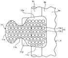
- FIG. 3 is a front view of the fastener element.
- FIG. 4 is a sectional view of the fastener element.
- FIG. 5 is a rear view showing the slide fastener when the back surface side of the fastener element is colored using an ink jet method.
- FIG. 6 is a front view of a fastener element according to a modification of the first embodiment.
- FIG. 7 is a rear view of the fastener element.
- FIG. 8 is an enlarged perspective view showing the fastener element of the slide fastener according to the second embodiment of the present invention.
- FIG. 1 is a front view showing a slide fastener according to Embodiment 1 of the present invention.
- FIG. 2 is an enlarged perspective view showing a fastener element of the slide fastener.
- FIG. 9 is a front view of the fastener element.
- FIG. 10 is a cross-sectional view of the fastener element.
- FIG. 11 is an enlarged perspective view showing a fastener element of a slide fastener according to Embodiment 3 of the present invention.
- FIG. 12 is a front view of the fastener element.
- FIG. 13 is an enlarged perspective view showing a fastener element of a slide fastener according to Embodiment 4 of the present invention.
- FIG. 14 is an enlarged perspective view showing a fastener element of a slide fastener according to Embodiment 5 of the present invention.
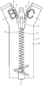
- FIG. 15 is a front view of a slide fastener that is colored not only on the fastener element but also on the top stopper and the separation / insertion tool.
- FIG. 16 is a front view of a slide fastener in which the slider is colored in addition to the fastener element.
- a fastener stringer and a slide fastener in which a plurality of synthetic resin fastener elements are attached by injection molding along one side edge of the fastener tape will be described.
- the stringer and the slide fastener are not limited thereto, and a plurality of metal fastener elements may be attached by die casting along one side edge of the fastener tape.
- FIG. 1 is a front view showing a slide fastener according to the first embodiment.
- FIG. 2 is an enlarged perspective view showing a fastener element of the slide fastener, and
- FIGS. 3 and 4 are a front view and a sectional view of the fastener element, respectively.
- the slide fastener 10 includes a pair of left and right fastener stringers 1 provided with an element row 2 on opposite tape side edges, left and right top stoppers 3 fixed to one end side of the element row 2, and an element.
- a separation fitting 4 disposed on the other end side of the row 2 and a slider 5 slidably disposed along the element row 2 in order to engage and separate the left and right element rows 2.
- the left and right fastener stringers 1 each include a fastener tape 6 and a plurality of fastener elements 11 made of synthetic resin attached to opposite tape side edges of the fastener tape 6.
- Each of the left and right fastener tapes 6 is woven or knitted into a narrow band, and has a tape main part 6a sewn to a fastener-attached product and an element attachment part 6b to which a plurality of fastener elements 11 are attached. is doing.
- a core string portion 6 c is provided at the tape side end edge of the fastener tape 6 on the element attachment portion 6 b side.
- the core string portion 6 c is formed in an enormous shape and is woven and knitted integrally with the fastener tape 6.
- the synthetic resin fastener elements 11 are arranged along the tape length direction by injection molding to form an element row 2.
- each fastener element 11 is formed symmetrically in the tape front and back direction with the fastener tape 6 interposed therebetween, and sandwiches the meshing head portion 11a having an oval shape in the tape length direction and the core string portion 6c.
- the body 11c fixed to the fastener tape 6 and the neck portion into which the meshing head 11a of the fastener element 11 to be meshed is fitted are formed so as to be constricted between the meshing head 11a and the body 11c.
- a concave groove 11e for fitting the shoulder portion 11d of the fastener element 11 which is a mating partner is formed in the peripheral wall surface on the distal end side of the meshing head portion 11a.
- each fastener element 11 has a first surface 12a disposed on the outer surface side of the slide fastener 10 and a second surface 12b disposed on the back surface side opposite to the first surface 12a.
- the 1st and 2nd surface 12a, 12b is formed over the meshing head 11a, the neck part 11b, and the trunk
- the first surface 12a is the front surface shown in FIG. 1, and the second surface 12b is the opposite surface.
- the first surface 12a of the fastener element 11 is provided with a plurality of concave portions 13 with respect to the plane portion, and the concave portions 13 are regularly arranged in a zigzag pattern.
- the staggered pattern means that the recesses 13 (the recesses 63 in Example 5 to be described later) are arranged in a row at intervals from the adjacent recesses 13 and form the recesses 13 forming one row. It is arranged so that it may be located between the recessed parts 13 which form the row
- the staggered arrangement is the same not only for the concave portion 13 but also for the convex portion 33 described later. By adopting a staggered arrangement in this manner, more concave portions 13 (or concave portions 63) or convex portions 33 can be formed in the same area.
- the ink droplets ejected on the first surface 12a are discharged. It functions as a fixing space for receiving and fixing.
- the recessed part 13 provided in each fastener element 11 has the hemispherical 1st recessed part 13a provided in the substantially whole 1st surface 12a, and the peripheral part along the ridgeline of the trunk
- the 1st recessed part 13a distribute
- all the concave portions 13 provided on the first surface 12a of the fastener element 11 may be set to the same size, or may be set to three or more different sizes.
- the shape of the recess 13 provided in the first surface 12a is not limited to a hemispherical shape, but a conical shape (see, for example, a fastener element 61 of Example 5 described later) or a frustum shape (conical shape). It is also possible to adopt a shape of a portion obtained by cutting the body in a plane parallel to the bottom surface and excluding the small cone portion, but all the recesses 13 provided in the first surface 12a have the same shape or A similar shape is preferred. Thereby, when the fastener element 11 is colored by the ink jet method, ink droplets can be stably fixed to the fastener element 11 and the appearance of the fastener element 11 can be improved.
- the recesses 13 provided in the fastener element 11 are arranged in a ratio of 1 to 25 per 1 mm 2 area.
- it is preferably arranged at a ratio of 9 or more and 16 or less as indicated by phantom lines in FIG.
- a total of nine concave portions 13 are arranged by eight concave portions 13 and two concave portions 13 halved by the virtual lines per 1 mm 2 region indicated by the virtual lines.
- the fastener tape 6 of the fastener stringer 1 is formed by weaving or knitting fibers, irregularities corresponding to the thickness of the fibers are formed on the tape surface. For this reason, when the fastener stringer 1 is colored by an ink jet method, a resolution of about 180 dpi is often adopted in consideration of the unevenness of the fastener tape 6 (for example, a fastener with a resolution higher than 180 dpi of about 720 dpi by the ink jet method). Even if the tape 6 is colored, it appears that the fastener tape 6 is actually colored at 180 dpi).
- the fastener element 11 is colored with a resolution of about 180 dpi by the inkjet method, in order to form an ink film having the above-described thickness, 0.002 mm 3 to 0.005 mm for one pixel. It was also revealed that an ink amount of 3 was required.
- the concave portion with respect to the area of 1 mm 2 of the first surface 12a in the fastener element 11 is required. If the ratio of 13 is less than one, each ink droplet (ink amount) ejected onto the surface of the fastener element 11 cannot be sufficiently received by each recess (fixing space portion) 13, and adjacent ink droplets Are mixed with each other, making it easy for patterns and colors to bleed or become rough.
- the ink droplets (ink amount) ejected on the surface of the fastener element 11 cannot be accurately received by the recess 13, and adjacent ink droplets are easily mixed with each other. Furthermore, in order to increase the ratio of the recesses 13 per 1 mm 2 area to more than 25, labor and cost for processing the mold for molding the fastener element 11 are increased, and the manufacturing cost of the fastener stringer 1 is greatly increased. It is also possible to increase it.
- the ratio of the recesses 13 per 1 mm 2 area of the first surface 12a is set to 1 or more and 25 or less, so that the first surface 12a of the fastener element 11 is injected.
- the ink droplets can be reliably received by the respective concave portions 13 (fixing space portions), and the ink droplets can be stably fixed on the first surface 12a. For this reason, it is possible to effectively prevent adjacent ink droplets from mixing with each other, and to suppress an increase in the manufacturing cost of the fastener stringer 1.
- the ratio of the concave portion 13 is set for the per area of 1 mm 2 as mentioned above, the 0.002 mm 3 ⁇ 0.005 mm 3 per pixel
- the volume of the space portion (fixing space portion) of each recess portion 13 (excluding a portion where the recess portion 13 is missing) provided in the fastener element 11. It was set to 0.002 mm 3 or more 0.27 mm 3 or less, further, the diameter of each recess 13 that is preferably set to 0.05mm or more 0.5mm or less revealed.
- the interval between the adjacent recesses 13 is preferably set to 0.05 mm or more and 0.3 mm or less.
- the diameter of the first recess 13a on the first surface 12a is 0.3 mm, and the volume of the space is set to 0.008 mm 3 .
- the diameter of the second recess 13b on the first surface 12a is 0.2 mm, and the volume of the space is set to 0.002 mm 3 .
- the interval between the first recesses 13a adjacent to each other is set to 0.05 mm.
- the 2nd recessed part 13b is distribute
- the interval is set to 0.10 mm.
- the fastener element 11 having the plurality of recesses 13 as described above is fixed to the fastener tape 6 with a predetermined shape by injection-molding synthetic resin onto the fastener tape 6 using an injection mold. Yes.
- a thermoplastic resin such as polyacetal, polypropylene, polybutylene terephthalate, or nylon can be used.
- a plurality of protrusions are provided on the cavity surface of the injection mold, and the plurality of protrusions are The cavity surface is formed by performing electric discharge machining.
- the above-described recess 13 is formed on the first surface 12a of the meshing head 11a, the neck 11b, and the trunk 11c, and the meshing head 11a, the neck 11b, and It is not formed in the side wall surface of the trunk
- the side wall surface facing the tape inward side of the body portion 11c is formed flat.
- the side wall surface is adjacent to the surface of the body portion 11c where adjacent fastener elements 11 arranged in a row face each other in the longitudinal direction of the fastener tape 6 and the longitudinal direction of the fastener tape 6 and is opposite to the meshing head portion 11a. And a surface facing the tape width direction on the side.
- the other side of the fastener tape 6 from the edge of the element attachment portion 6 b is the tape outer side, and opposite to the tape outer side, from the edge of the element attachment portion 6 b to the tape main body portion 6 a.
- the side is the inside of the tape.
- that the side wall surface is flat means that the fixing space portion (concave portion 13) as described above is not disposed on the side wall surface.
- the boundary between the fastener tape 6 and the fastener element 11 is determined when the slide fastener 10 is viewed from the front side.
- the pattern and color given over the fastener tape 6 and the fastener element 11 can be made to appear as continuous without being interrupted at the boundary between the fastener tape 6 and the fastener element 11. .
- the surfaces of the shoulder portion 11d on the first surface 12a side and the second surface 12b side are flat, and no fixing space (concave portion 13) is formed on any surface.
- the shoulder portion 11d is a portion that fits into the groove 11e of the mating counterpart when the left and right fastener elements 2 are engaged. For this reason, since the recessed part 13 is not formed in the 1st surface 12a and the 2nd surface 12b of the shoulder part 11d, when the meshed right and left fastener elements 2 receive the force of the tape front and back direction, the shoulder part 11d
- the contact area between the first surface 12a or the second surface 12b and the inner wall surface of the groove 11e is increased, and the strength to withstand the force in the front and back direction can be easily ensured.
- the left and right top stoppers 3, the separation / insertion insertion tool 4, and the slider 5 are configured in the same manner as those generally used conventionally. That is, the left and right top stoppers 3 are fixed to one end side of the element row 2 by injection molding the same type of synthetic resin as the fastener element 11, and the slider 5 can be removed from one end side of the element row 2. It is preventing.
- the opening / closing insertion tool 4 includes a wing stick, a box stick, and a box, and the wing stick is configured to be removable from the box.
- the slider 5 includes an upper wing plate, a lower wing plate, a guide column connecting the upper and lower wing plates, an upper and lower flange extending from the left and right side edges of the upper and lower wing plates, and an upper wing plate. It has a handle attachment column erected on the upper surface and a handle attached rotatably to the handle attachment column.
- a dyeing method by an ink jet method as described in Patent Document 1 is used, and 180 dpi is applied to the fastener tape 6 and the fastener element 11.
- 180 dpi is applied to the fastener tape 6 and the fastener element 11.
- the slide fastener 10 of the first embodiment is transferred from the inkjet nozzle installed at a predetermined position while conveying the slide fastener 10 of the first embodiment at a predetermined speed in the tape length direction.
- the dye-based ink droplets are ejected toward the entire tape width direction of the fastener tape 6 toward the outer surface (the surface on the same side as the first surface 12a of the fastener element 11).
- the ink jet nozzle ejects ink from an ultrasonic head disposed on the nozzle, and the ultrasonic head causes ultrasonic vibration to the ink, thereby ejecting the ink in a minute droplet state.
- the ink jet nozzle when an ink droplet is ejected from the ultrasonic head, an electric charge is given to the ink droplet by the electrode.
- the ink droplet ejected from the ultrasonic head passes through the deflection electrode disposed in the inkjet nozzle, the trajectory of the ink droplet is bent in a required direction by the electric charge applied to the ink droplet.
- the fastener tape 6 and the fastener element 11 are sprayed so as to form a desired pattern and color.
- the ink droplets sprayed onto the fastener tape 6 are fixed to the fastener tape 6 by, for example, soaking into the fibers constituting the fastener tape 6. Further, the ink droplets sprayed onto the fastener element 11 are received by the plurality of hemispherical concave portions 13 arranged in a staggered manner on the first surface 12a of the fastener element 11 and fixed on the first surface 12a. .
- each ink droplet sprayed on the fastener element 11 is recessed.
- the ink droplets can be reliably fixed to the first surface 12 a of the fastener element 11 by being received by the fixing space 13.
- the second recessed portion 13b formed smaller than the first recessed portion 13a is disposed on the peripheral portion of the body portion 11c, and the peripheral portion and the neck portion of the meshing head portion 11a. Since the first concave portion 13a formed so that a part of the hemisphere is cut off is arranged at the peripheral portion of the 11b and the peripheral portion of the body portion 11c, ink droplets are also formed on the peripheral portion of the first surface 12a. Can be stably received and fixed by the first and second recesses 13a and 13b.
- the heat treatment is performed, for example, by a process of passing the slide fastener 10 in a heated atmosphere, and is also called a dry heat treatment.
- ink droplets are sprayed onto the slide fastener 10 having a predetermined length to perform heat treatment.
- ink is applied to the continuous fastener stringer 1 before being cut to a predetermined length.
- the droplets are sprayed and attached, and then the continuous fastener stringer 1 is dyed by heat treatment, and then the top stopper 3, the release fitting 4 and the slider 5 are attached to the pair of fastener stringers 1.
- the slide fastener 10 can also be obtained by cutting to a predetermined length after mounting.
- the slide fastener 10 is colored using a dye-based ink.
- a slide fastener using a pigment-based ink instead of the dye-based ink is described. It is also possible to color 10.
- the pigment-based ink is a type of ink in which the dye is not dissolved in the solvent but is dispersed in the solvent, unlike the dye-based ink in which the dye is dissolved in the solvent. Even when the slide fastener 10 is colored using such a pigment-based ink, the ink droplets can be stably fixed to the fastener element 11, and the contour of the pattern and color can be clearly displayed.
- the fastener tape 6 and the fastener element 11 when coloring the fastener tape 6 and the fastener element 11 as mentioned above, it can color in the form of the slide fastener 10, and also the form of the fastener chain and the form of the fastener stringer 1 It is also possible to color with.
- the slide fastener 10 in the first embodiment can be dyed by post-dyeing instead of being colored using the ink jet method as described above.
- dyeing is performed in the form of the fastener chain before the slider 5 is attached or in the form of the fastener stringer 1.
- the fastener chain (or fastener stringer 1) is wrapped around the dyeing beam in layers, and further, the fastener chain is wound around the beam and accommodated in the dyeing pot, and the fastener chain is placed in the dyeing pot. Stain.
- a plurality of recesses 13 are formed on the first surface 12a of each fastener element 11 over the entire surface. Further, the portion of the first surface 12a where the concave portion 13 is not arranged looks like it is formed in a plane when visually observed, but when observed in the order of micrometers with a microscope or the like, Due to the formation of the recess 13, a high portion and a low portion are also formed in the same plane, and the same plane has a slight height difference.
- the fastener chain can be uniformly and stably dyed with a desired color without causing color unevenness in the fastener element 11.
- the slide fastener 10 of the first embodiment can be subjected to a coloring process for painting the first surface 12a of the fastener element 11 by spraying.
- a metal plating process may be performed on the fastener element 11 or a surface treatment may be performed to form a film on the surface of the fastener element 11 by performing a vapor deposition process on the fastener stringer 1 in a predetermined atmosphere (for example, in an aluminum atmosphere). it can.
- a predetermined atmosphere for example, in an aluminum atmosphere.
- the surface treatment which sticks a sheet-like film on the surface of the fastener element 11 by thermal transfer can also be performed.
- each of the concave portions 13 has a fine fixing space portion having a predetermined volume, a part of the coating film or the film enters the fixing space portion and is reliably fixed.
- the adhesion strength between the first surface 12a of the fastener element 11 and the coating film or film formed on the first surface 12a can be greatly increased, and therefore the coating film formed on the fastener element 11 Alternatively, the film can be made difficult to peel.
- dyeing means that the dye dyes the surface of the resin and the inside of the vicinity of the surface, and painting means that colors are laminated on the surface.
- material dyed with the same dye for a fastener tape and a fastener element For example, when the material of the fastener tape is polyester resin, it is preferable to use polyester resin or polybutylene terephthalate for the fastener element.
- the fastener element is made of polyamide resin. Is preferably used.
- a plurality of recesses 13 are arranged on the first surface 12a of each fastener element 11, and each recess 13 Since a fine fixing space portion having a predetermined volume is formed in the adhesive, an adhesive enters the fixing space portion and reliably fixes.
- the adhesive strength between the first surface 12a of the fastener element 11 and the film attached to the first surface 12a can be significantly increased, and therefore the adhesive element is attached to the first surface 12a of the fastener element 11.
- the film can be made difficult to peel off.
- the concave portion 13 is formed only on the first surface 12a of the fastener element 11 is described.
- the present invention is not limited to this, and the hemispherical recess 13 may be formed not only on the first surface 12a of the fastener element 11, but only on the second surface 12b on the opposite side, It may be formed on both surfaces of the first surface 12a and the second surface 12b.
- hemispherical recesses 13 are formed on both the first surface 12a and the second surface 12b of the fastener element 11, as shown in FIG.
- a desired pattern or color is colored on the outer surface (first surface 12a) side of the element 11, and a desired pattern is also formed on the back surface (second surface 12b) side of the fastener tape 6 and the fastener element 11 as shown in FIG. (For example, letters of the alphabet) and colors can be easily colored.
- the fastener element 11 has a symmetrical shape on the front surface side and the back surface side of the fastener tape 6.
- the fastener element 11 is the fastener tape 6.
- the front surface side and the back surface side may have different shapes.
- the fastener element 21 has different shapes on the front surface side and the back surface side of the fastener tape 6. ing. That is, the half part (refer FIG. 7) distribute
- FIG. 6 a half portion (see FIG. 6) arranged on the tape back surface side of the fastener element 21 is a barrel portion 21c fixed to the fastener tape 6 and an abbreviated portion extending outward from the barrel portion 21c. And a triangular head 21a.
- the surface of the trunk portion 11c, the neck portion 11b, and the meshing head portion 11a arranged on the tape surface side becomes the first surface 22a
- the surface of the trunk portion 21c and the head portion 21a arranged on the tape rear surface side is the second surface. It becomes the surface 22b.
- a plurality of recesses 13 are arranged in a staggered manner on both the first surface 22a and the second surface 22b of the fastener element 21 according to this modification, and are arranged on the first and second surfaces 22a, 22b.
- the recesses 13 are all formed in a hemispherical shape having the same size.
- the recesses 13 disposed on the first and second surfaces 22a and 22b are disposed at a rate of 1 to 25, preferably 9 to 16 per 1 mm 2 area. Yes.
- each recess 13 arranged in 22b has a 0.002 mm 3 or more 0.27 mm 3 or less of the volume And a diameter of 0.05 mm or more and 0.5 mm or less. Furthermore, on the first and second surfaces 22a and 22b, the interval between the adjacent recesses 13 is set to 0.05 mm or more and 0.3 mm or less.
- both the front and back surfaces of the fastener tape 6 and the fastener element 21 are formed by an inkjet method.
- the ink droplets sprayed on the first surface 22a of the fastener element 21 are received by the plurality of hemispherical concave portions 13 arranged in a staggered manner in the same manner as in the first embodiment. It can be stably fixed on the first surface 22a.
- ink droplets sprayed on the second surface 22b of the fastener element 21 are received by the plurality of hemispherical concave portions 13 arranged in a staggered manner, and are stably fixed on the second surface 22b. be able to.
- a desired pattern or color is continuously dyed on both the front and back surfaces of the fastener tape 6 and the fastener element 21 by performing heat treatment on the slide fastener 20 in which ink droplets adhere to both the front and back surfaces of the fastener tape 6 and the fastener element 21.
- the slide fastener 20 in which the pattern and color outline are clearly formed can be obtained.
- the design of the pattern is not particularly limited, and the pattern includes a pattern formed with two or more colors.
- the slide fastener 20 is a fastener element in which a coloring process is performed by spraying, or a surface process such as a metal plating process or a vapor deposition process, or a surface process in which a sheet-like film is adhered by thermal transfer.
- a coloring process is performed by spraying, or a surface process such as a metal plating process or a vapor deposition process, or a surface process in which a sheet-like film is adhered by thermal transfer.
- the coating film, coating, or film disposed on the first and second surfaces 22a and 22b is increased in adhesion strength or adhesion strength to be applied.
- the film, coating, or film can be made difficult to peel from the first and second surfaces 22a, 22b.
- the half part on the first surface 22 a side and the half part on the second surface 22 b side of the fastener element 21 are different in shape from each other, and a different impression can be given to the user.
- the recess 13 is not formed. This is because when the left and right fastener elements 21 are engaged with each other, the surface on the second surface 22b side of the meshing head 11a and the surface on the first surface 22a side of the head 21a of the mating counterpart are brought into contact with each other in a wider area. This is to ensure the strength to withstand the force in the tape front and back direction.
- FIG. 8 is an enlarged perspective view showing the fastener element of the slide fastener according to the second embodiment.
- FIG. 9 is a front view of the fastener element, and
- FIG. 10 is a cross-sectional view of the fastener element.
- the first surface 32a of each fastener element 31 has a plurality of A hemispherical convex portion 33 is provided, and the other configuration is substantially the same as that of the slide fastener 30 according to the first embodiment.
- the configuration of the plurality of convex portions 33 provided on the first surface 32a of each fastener element 31 will be mainly described, and the configuration similar to the slide fastener 30 of the first embodiment described above is provided.
- the parts and members are denoted by the same reference numerals and the description thereof is omitted.
- parts and members having the same configuration as those of the slide fastener 10 of the first embodiment are denoted by the same reference numerals, and the description thereof is omitted. I will do it.
- each fastener element 31 according to the second embodiment a plurality of hemispherical convex portions 33 having the same shape and size are arranged in a staggered manner on substantially the entire first surface 32a.
- these convex parts 33 may be formed in different sizes.
- the shape of the convex part 33 is not limited to hemispherical shape, A cone shape and a frustum shape are also employable.
- the convex portion 33 provided in each fastener element 31 is arranged at a ratio of 25 or less 1 or more per area of 1 mm 2.
- it is preferably arranged at a ratio of 9 or more and 16 or less.
- the convex portion 33 is formed on the first surface 32a, so that the plane connecting the vertices of the convex portions 33 and the flat first surface 32a of the fastener element 31 are formed. A space is formed between them.
- Such a space portion formed in the second embodiment functions as a fixing space portion for receiving and fixing ink droplets when the fastener element 31 is colored by, for example, an ink jet method, and, for example, a rear portion of the fastener chain.
- the dye functions as a fixing space for distributing the dye and spreading the dye to the first surface 32 a of the fastener element 31.
- the volume of the fixing space formed on one of the projections 33 is set to 0.002 mm 3 or more 0.27 mm 3 or less.
- the volume of the fixing space formed with respect to one convex portion 33 is obtained, for example, by calculating the volume of the fixing space in a predetermined area, and the volume of the fixing space determined as the predetermined This is a numerical value obtained by dividing by the number of convex portions 33 arranged in the region.
- each convex portion 33 arranged on the first surface 32a on the first surface 32a is set to 0.05 mm or more and 0.5 mm or less, and the interval between the adjacent convex portions 33 is 0. It is set to 05 mm or more and 0.3 mm or less.
- the fastener tape 6 and the fastener element 31 have a resolution of 180 dpi by the inkjet method.
- the ink droplets sprayed on the first surface 32a of the fastener element 31 are received by fixing spaces of a predetermined capacity formed around the respective convex portions 33 arranged in a staggered pattern, and the ink droplets are received. Can be stably fixed to the first surface 32 a of the fastener element 31. For this reason, it can prevent effectively that the adjacent ink droplets adhering to the 1st surface 32a mix.
- the slide fastener 30 is obtained in which the outline of the color is clearly formed and the appearance is improved.
- the fixing space portion having a predetermined volume on the first surface 32a of each fastener element 31. is arranged around each convex portion 33, so that the dye can be more smoothly distributed to the front and back surfaces of the fastener element 31 when the fastener chain is wound around the beam and dyeing is performed in the dyeing pot. .
- the fastener chain can be uniformly and stably dyed with a desired color without causing color unevenness in the fastener element 31.
- the slide fastener 30 according to the second embodiment is applied with a color treatment for painting by spraying, or a surface treatment such as metal plating treatment or vapor deposition treatment or a surface treatment for attaching a sheet-like film by thermal transfer.
- a fixing space having a predetermined volume is arranged on the first surface 32a of each fastener element 31 around each convex portion 33. The adhesion strength or adhesive strength between the surface 32a and the coating film, film or film formed on the first surface 32a is increased, and the coating film, film or film can be made difficult to peel from the first surface 32a.
- FIG. 11 is an enlarged perspective view showing the fastener element of the slide fastener according to the third embodiment
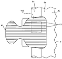
- FIG. 12 is a front view of the fastener element.
- a fastener tape is provided on the first surface 42a of each fastener element 41 in place of the plurality of hemispherical concave portions 13 provided in the fastener element 11 of the first embodiment.
- a plurality of groove-like recesses 43 formed in parallel with the tape width direction of 6 are provided.
- the slide fastener 40 according to the third embodiment has the above-described slide fastener according to the first embodiment except that the groove-shaped recess 43 as described above is provided on the first surface 42a of the fastener element 41. 10 has substantially the same configuration.
- each fastener element 41 a plurality of groove-like recesses 43 parallel to the tape width direction are arranged substantially at the predetermined distance from each other over substantially the entire first surface 42a.
- each groove-shaped recess 43 has a semicircular cross section, and the groove width of each recess 43 is set to the same size.
- the space formed inside these recesses 43 functions as a fixing space.
- between each recessed part 43 can be recognized as a convex part, and the several surface-like convex part parallel to a tape width direction is distribute
- each groove-like recess 43 may be formed in a different size as long as it has a similar cross-sectional shape.
- the cross-sectional shape of the groove-like recess 43 is not limited to a semicircular shape, and a triangular shape or a rectangular shape may be employed.
- the groove-like recesses 43 arranged in each fastener element 41 are arranged at a rate of 1 to 25 per 1 mm 2 area as indicated by phantom lines in FIG. That is, groove-like recesses 43 are arranged at a rate of 1 to 25 in the 1 mm interval in the tape length direction.
- the groove-shaped concave portions 43 are arranged at a ratio of 3 to 4 in a 1 mm interval.
- the groove width dimension in each groove-shaped recess 43 is set to 0.05 mm or more and 0.5 mm or less, and the interval between the groove-shaped recesses 43 is set. Is set to 0.05 mm or more and 0.3 mm or less.
- the fastener tape 6 and the fastener element 41 are formed by the inkjet method on the slide fastener 40 of the third embodiment having the fastener element 41 in which the plurality of groove-shaped recesses 43 are formed on the first surface 42a.
- the ink droplets sprayed on the first surface 42a of the fastener element 41 are received by the fixing space portions of the plurality of groove-shaped recesses 43 arranged in parallel to the tape width direction, Ink droplets can be stably fixed on the first surface 42 a of the fastener element 41. For this reason, it can prevent effectively that the adjacent ink droplets adhering to the 1st surface 42a mix.
- the slide fastener 40 is obtained in which the outline of the color is clearly formed and the appearance is improved.
- the fastener chain for the slide fastener 40 according to the third embodiment is dyed by post-dyeing, a plurality of groove-shaped recesses as described above are formed on the first surface 42a of each fastener element 41. Since 43 is formed, when the same fastener chain is wound around the beam and dyeing is performed in the dyeing pot, the dye can be more smoothly distributed on the front and back surfaces of the fastener element 41. Therefore, the fastener chain can be uniformly and stably dyed with a desired color without causing color unevenness in the fastener element 41.
- the slide fastener 40 according to the third embodiment has a sheet-like shape by coloring treatment for coating the first surface 42a of the fastener element 41 by spraying, surface treatment such as metal plating treatment or vapor deposition treatment, or thermal transfer.
- surface treatment such as metal plating treatment or vapor deposition treatment
- thermal transfer When the surface treatment for attaching the film is performed on the first surface 42a of the fastener element 41, the first surface 42a of each fastener element 41 is formed with a plurality of groove-shaped recesses 43.
- the adhesion strength or adhesive strength between the surface 42a and the coating film, film or film formed on the first surface 42a is increased, and the coating film, film or film can be made difficult to peel from the first surface 42a. .
- FIG. 13 is an enlarged perspective view of the fastener element of the slide fastener according to the fourth embodiment.
- a tape is provided on the first surface 52a of each fastener element 51.
- a plurality of groove-like recesses 53 parallel to the length direction are provided.
- the slide fastener 50 according to the fourth embodiment has substantially the same configuration as the slide fastener 40 according to the above-described third embodiment, except that the groove-shaped recess 53 is provided in the tape length direction. Have.
- each fastener element 51 in the fourth embodiment a plurality of groove-like recesses 53 parallel to the tape length direction are arranged on the substantially entire first surface 52a at predetermined intervals.
- each groove-shaped recess 53 has a semicircular cross section, and the groove width of each recess 53 is set to the same size.
- the space formed inside the recess 53 functions as a fixing space.
- the groove-like recesses 53 arranged in each fastener element 51 are in a ratio of 1 to 25 per 1 mm 2 area (that is, 1 or more in an interval of 1 mm in the tape width direction). (At a rate of 25 or less).
- the number of the concave portions 53 is arranged at a ratio of 3 or more and 4 or less.
- each groove-shaped recess 53 is set to 0.05 mm or more and 0.5 mm or less, and the interval between the groove-shaped recesses 53 is set. Is set to 0.05 mm or more and 0.3 mm or less.
- the fastener tape 6 and the fastener element 51 are formed by the inkjet method on the slide fastener 50 of the fourth embodiment having the fastener element 51 in which a plurality of groove-shaped recesses 53 are formed on the first surface 52a.
- the ink droplets sprayed on the first surface 52a of the fastener element 51 are received by a plurality of groove-shaped concave portions 53 arranged in parallel to the tape length direction, and the ink droplets are received. It can be stably fixed to the first surface 52a of the fastener element 51. For this reason, it can prevent effectively that the adjacent ink droplets adhering to the 1st surface 52a mix.
- the first surface 52a of the fastener element 51 is applied to the slide fastener 50 by spraying.
- a coloring process or when a surface process such as a metal plating process or a vapor deposition process or a surface process for attaching a sheet-like film by thermal transfer is performed on the first surface 52a of the fastener element 51, The same effect as in the third embodiment can be obtained.
- the arrangement direction of the groove-like recesses 43 and 53 is not limited to the tape width direction or the direction parallel to the tape length direction, and for example, the recesses are inclined in a direction inclined at a predetermined angle with respect to the tape width direction. 43 and 53 may be provided.
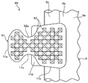
- FIG. 14 is an enlarged front view of the fastener element of the slide fastener according to the fifth embodiment.
- the slide fastener 60 according to the fifth embodiment instead of the plurality of hemispherical concave portions 13 provided on the fastener element 11 of the first embodiment described above, a plurality of hemispherical recesses 13 are provided on the first surface 62a of each fastener element 61.
- a concave portion 63 having a regular square pyramid shape is provided.
- each fastener element 61 in the fifth embodiment a plurality of regular square pyramid-shaped recesses 63 having the same dimensions are arranged in a staggered manner on the first surface 62a.
- the space formed inside these recesses 63 functions as a fixing space.
- each recess 63 provided on the first surface 62a are all formed in the same shape and size, and the ratio is 1 to 25, preferably 9 to 16 per 1 mm 2 area. Arranged in proportion. Further, each recess 63 arranged in the first surface 62a has a 0.002 mm 3 or more 0.27 mm 3 or less of the volume, and, the length of one side on the first surface 62a of the recess 63, 0 .05 mm or more and 0.5 mm or less.
- the fastener tape 6 and the fastener are fastened by the inkjet method to the slide fastener 60 of the fifth embodiment having the fastener element 61 in which the first surface 62a has a plurality of regular square pyramid-shaped recesses 63 formed.
- the ink droplets sprayed on the first surface 62a of the fastener element 61 are received by the plurality of concave portions 63 having a regular quadrangular pyramid shape, and the ink droplets of the fastener element 61 are received. It can be stably fixed on the first surface 62a. For this reason, it can prevent effectively that the adjacent ink droplets adhering to the element surface mix.
- a plurality of concave portions 63 having a regular square pyramid shape are formed on the first surface 62a of each fastener element 61.
- a portion of the first surface 62a where the concave portion 63 is not disposed is observed with a microscope or the like on the order of micrometers, a slight difference in height is formed in the same plane.
- the concave portions or the convex portions formed in the fastener elements 11 to 61 are also formed on the first surface and / or the second surface of the top stopper 3 and the separation fitting 4.
- a concave portion or a convex portion having the same shape (or similar shape) can be provided under the same conditions as those of the fastener elements 11 to 61.
- the top stopper 3 and the release fitting 4 can be colored by the ink jet method.
- the desired pattern and color are attached to the top stopper 3 and the opening / closing insertion tool 4 so as to be continuous from the fastener tape 6 and the fastener elements 11 to 61, and the outline of the pattern and color is clear and beautiful. Can be formed. Therefore, for example, as shown in FIG. 15, the pattern (for example, letters of the alphabet) and colors that are continuous with the fastener tape 6, the fastener element 11, and the top stopper 3 or the separation / insertion tool 4 are beautiful. And can be attached stably.
- the first surface and / or the second surface of the slider have the same shape (or similar shape) as the concave portion or the convex portion formed in the fastener elements 11 to 61.
- the concave portion or the convex portion can be provided under the same conditions as the fastener elements 11 to 61.
- a slider 8 referred to as a flat slider in which a handle is rotatably attached to the side surface of the slider and the upper blade is easily exposed on the surface. In some cases).
- a desired pattern for example, letters of the alphabet
- color is applied to the slider 8 as a fastener tape 6 or a fastener element. 11 and the contour of the pattern and color can be clearly and clearly formed. For this reason, the pattern and color which continue to the fastener tape 6, the fastener element 11, and the slider 8 can be attached beautifully and stably.
- the concave or convex portion on the surface of the fastener element is formed simultaneously with the injection molding or die casting of the fastener element.
- the present invention is not limited to this, for example, after the fastener element is molded.
- the concave portion or the convex portion may be formed by post-processing. In this case, as post-processing, it is possible to use processing that presses a roller having unevenness against the fastener element, or processing by cutting.
- the resin layer formed on the surface of the fastener element does not fill the fixing space portion of the concave portion or the convex portion on the surface of the fastener element even after coating, the subsequent coloring (dyeing) with the coloring material is performed.
- the colorant can be stably fixed in the fixing space.
- the colored fastener element can be given a unique color to metal.
Landscapes
- Slide Fasteners (AREA)
- Ink Jet (AREA)
Abstract
Description
前記特許文献1に記載されているスライドファスナーの染色方法は、先ず、合成樹脂製のファスナーエレメントを備えるスライドファスナーの一表面に対して、インクジェットノズルからインク滴を噴射することにより、スライドファスナーの表面に模様を形成する。その後、模様が付されたスライドファスナーに熱処理を行うことによって、スライドファスナーに付着した染料をファスナーテープとファスナーエレメントに染着させている。
また、本発明に係るファスナーストリンガーにおいて、互いに隣接する前記凹部間、又は互いに隣接する前記凸部間に所定の間隔が設けられていることが好ましい。
この場合、1つの前記凹部又は前記凸部に対して形成される空間部の容積が、0.002mm3以上0.27mm3以下に設定されていることが好ましい。また、前記ファスナーエレメントの前記一面に配される複数の前記凹部又は前記凸部は、互いに同一の形状に又は相似形に形成されていることが好ましい。更に、前記ファスナーエレメントの前記一面に配される複数の前記凹部又は前記凸部は、千鳥状に配されていることが好ましい。
更に、本発明のファスナーストリンガーにおいて、前記ファスナーエレメントは、インクジェット方式により着色されていることが好ましく、特に、前記ファスナーエレメント及び前記ファスナーテープとに模様が着色されていることが好ましい。或いは、前記ファスナーエレメントは、後染色により着色されていても良い。
即ち、左右の上止3は、ファスナーエレメント11と同じ種類の合成樹脂を射出成形することにより、エレメント列2の一端側に固着されており、エレメント列2の一端側からスライダー5が抜けることを防止している。
スライダー5は、上翼板と、下翼板と、上下翼板間を連結する案内柱と、上下翼板の左右側端縁から互いに接近するに延設された上下フランジと、上翼板の上面に立設された引手取付柱と、引手取付柱に回動可能に取り付けられた引手とを有している。
この後染めを行う場合、スライダー5が取り付けられる前のファスナーチェーンの形態や、ファスナーストリンガー1の形態にて染色が行われる。例えば、ファスナーチェーン(又はファスナーストリンガー1)を染色用のビームに何層にも重ねて巻き付け、更に、そのファスナーチェーンをビームに巻き付けた状態のまま染色釜に収容し、同染色釜内でファスナーチェーンを染色する。
本実施例3に係るスライドファスナー40では、各ファスナーエレメント41の第1表面42aに、前述の実施例1のファスナーエレメント11に設けられている複数の半球体状の凹部13の代わりに、ファスナーテープ6のテープ幅方向と平行に形成された複数の溝状の凹部43が設けられている。なお、本実施例3に係るスライドファスナー40は、ファスナーエレメント41の第1表面42aに上述のような溝状の凹部43が設けていることを除いては、前述の実施例1に係るスライドファスナー10と実質的に同様の構成を有する。
本実施例4に係るスライドファスナー50では、各ファスナーエレメント51の第1表面52aに、前述の実施例3のファスナーエレメント41においてテープ幅方向と平行な複数の溝状の凹部43の代わりに、テープ長さ方向と平行な複数の溝状の凹部53が設けられている。なお、本実施例4に係るスライドファスナー50は、溝状の凹部53をテープ長さ方向に設けたことを除いては、前述の実施例3に係るスライドファスナー40と実質的に同様の構成を有する。
本実施例5に係るスライドファスナー60では、各ファスナーエレメント61の第1表面62aに、前述の実施例1のファスナーエレメント11に設けられている複数の半球体状の凹部13の代わりに、複数の正四角錘体状の凹部63が設けている。
2 エレメント列
3 上止
4 開離嵌挿具
5 スライダー
6 ファスナーテープ
6a テープ主体部
6b エレメント取付部
6c 芯紐部
8 スライダー
10 スライドファスナー
11 ファスナーエレメント
11a 噛合頭部
11b 首部
11c 胴部
11d 肩部
11e 凹溝
12a 第1表面
12b 第2表面
13 凹部
13a 第1凹部
13b 第2凹部
20 スライドファスナー
21 ファスナーエレメント
21a 頭部
21b 胴部
22a 第1表面
22b 第2表面
30 スライドファスナー
31 ファスナーエレメント
32a 第1表面
33 凸部
40 スライドファスナー
41 ファスナーエレメント
42a 第1表面
43 凹部
50 スライドファスナー
51 ファスナーエレメント
52a 第1表面
53 凹部
60 スライドファスナー
61 ファスナーエレメント
62a 第1表面
63 凹部
Claims (14)
- ファスナーテープ(6) と、前記ファスナーテープ(6) の一側縁部に沿って取着された複数のファスナーエレメント(11,21,31,41,51,61) とを有し、前記ファスナーエレメント(11,21,31,41,51,61) の少なくとも一面に着色処理又は表面処理が施されるファスナーストリンガー(1) であって、
前記ファスナーエレメント(11,21,31,41,51,61) の前記着色処理又は前記表面処理が施される少なくとも一面に、複数の微細な定着空間部が配されてなることを特徴とするファスナーストリンガー。 - 前記ファスナーエレメント(11,21,31,41,51,61) の着色処理又は表面処理が施される少なくとも一面に、凹部(13,43,53,63) 又は凸部(33)が1mm2当たりに1個以上25個以下の割合で配され、
前記定着空間部は、前記凹部(13,43,53,63) 内に形成される空間部、又は前記凸部(33)の周囲に形成される空間部により構成されてなる、
請求項1記載のファスナーストリンガー。 - 互いに隣接する前記凹部(13,43,53,63) 間、又は互いに隣接する前記凸部(33)間に所定の間隔が設けられてなる請求項2記載のファスナーストリンガー。
- 前記凹部(13,63) 又は前記凸部(33)は、半球体状、錐体状、又は錐台状に形成されてなる請求項2又は3記載のファスナーストリンガー。
- 1つの前記凹部(13,63) 又は前記凸部(33)に対して形成される空間部の容積が、0.002mm3以上0.27mm3以下に設定されてなる請求項4記載のファスナーストリンガー。
- 前記ファスナーエレメントの前記一面に配される複数の前記凹部(13,63) 又は前記凸部(33)は、互いに同一の形状に又は相似形に形成されてなる請求項4記載のファスナーストリンガー。
- 前記ファスナーエレメントの前記一面に配される複数の前記凹部(13,63) 又は前記凸部(33)は、千鳥状に配されてなる請求項4記載のファスナーストリンガー。
- 前記凹部(43,53) 又は前記凸部は、所定の方向に沿った溝状又は畝状に形成されてなる請求項2又は3記載のファスナーストリンガー。
- 前記ファスナーエレメント(11,21,31,41,51,61) は、インクジェット方式により着色されてなる請求項2又は3記載のファスナーストリンガー。
- 前記ファスナーエレメント(11,21,31,41,51,61) 及び前記ファスナーテープ(6) とに模様が着色されてなる請求項2又は3記載のファスナーストリンガー。
- 前記ファスナーエレメント(11,21,31,41,51,61) は、後染色により着色されてなる請求項2又は3記載のファスナーストリンガー。
- 前記ファスナーエレメント(11,21,31,41,51,61) は、前記ファスナーテープ(6) に固着される胴部(11c) と、前記胴部(11c) からテープ外方に延出した首部(11b) と、前記首部(11b) の先端に配された噛合頭部(11a) とを有し、
前記胴部(11c) のテープ内方側に向いた側壁面が平坦に形成されてなる、
請求項2又は3記載のファスナーストリンガー。 - 請求項1~12のいずれかに記載の前記ファスナーストリンガー(1) を有することを特徴とするスライドファスナー。
- 前記ファスナーエレメント(11,21,31,41,51,61) により形成されるエレメント列(2) の一端側に配される上止(3) 、前記エレメント列(2) の他端側に配される下止又は開離嵌挿具(4) 、及び、前記エレメント列(2) に沿って摺動可能なスライダー(5,8) のうちの少なくとも1つは、複数の凹部(13,43,53,63) 又は凸部(33)を、前記ファスナーエレメント(11,21,31,41,51,61) の前記凹部(13,43,53,63) 又は前記凸部(33)が配されている一面と同じ方向を向く面に、1mm2当たりに1個以上25個以下の割合で有してなる請求項13記載のスライドファスナー。
Priority Applications (9)
| Application Number | Priority Date | Filing Date | Title |
|---|---|---|---|
| EP10849420.4A EP2556766B1 (en) | 2010-04-06 | 2010-04-06 | Fastener stringer and slide fastener |
| CN201080065864.1A CN102821639B (zh) | 2010-04-06 | 2010-04-06 | 拉链条以及拉链 |
| US13/639,493 US8938863B2 (en) | 2010-04-06 | 2010-04-06 | Fastener stringer and slide fastener |
| PCT/JP2010/056239 WO2011125176A1 (ja) | 2010-04-06 | 2010-04-06 | ファスナーストリンガー及びスライドファスナー |
| JP2012509225A JP5583205B2 (ja) | 2010-04-06 | 2010-04-06 | ファスナーストリンガー及びスライドファスナー |
| KR1020127026097A KR101428900B1 (ko) | 2010-04-06 | 2010-04-06 | 파스너 스트링거 및 슬라이드 파스너 |
| ES10849420.4T ES2598493T3 (es) | 2010-04-06 | 2010-04-06 | Banda portadora de cierre y cierre de cremallera |
| HK13101921.7A HK1174509B (en) | 2010-04-06 | Fastener stringer and slide fastener | |
| TW099133105A TWI500400B (zh) | 2010-04-06 | 2010-09-29 | Zipper chain and zipper |
Applications Claiming Priority (1)
| Application Number | Priority Date | Filing Date | Title |
|---|---|---|---|
| PCT/JP2010/056239 WO2011125176A1 (ja) | 2010-04-06 | 2010-04-06 | ファスナーストリンガー及びスライドファスナー |
Publications (1)
| Publication Number | Publication Date |
|---|---|
| WO2011125176A1 true WO2011125176A1 (ja) | 2011-10-13 |
Family
ID=44762163
Family Applications (1)
| Application Number | Title | Priority Date | Filing Date |
|---|---|---|---|
| PCT/JP2010/056239 Ceased WO2011125176A1 (ja) | 2010-04-06 | 2010-04-06 | ファスナーストリンガー及びスライドファスナー |
Country Status (8)
| Country | Link |
|---|---|
| US (1) | US8938863B2 (ja) |
| EP (1) | EP2556766B1 (ja) |
| JP (1) | JP5583205B2 (ja) |
| KR (1) | KR101428900B1 (ja) |
| CN (1) | CN102821639B (ja) |
| ES (1) | ES2598493T3 (ja) |
| TW (1) | TWI500400B (ja) |
| WO (1) | WO2011125176A1 (ja) |
Cited By (6)
| Publication number | Priority date | Publication date | Assignee | Title |
|---|---|---|---|---|
| WO2013145257A1 (ja) * | 2012-03-30 | 2013-10-03 | Ykk株式会社 | スライドファスナー |
| WO2014013616A1 (ja) * | 2012-07-20 | 2014-01-23 | Ykk株式会社 | ファスナーストリンガー及びスライドファスナー |
| WO2014199492A1 (ja) * | 2013-06-13 | 2014-12-18 | Ykk株式会社 | ファスナー部品、スライドファスナー及びファスナー部品の製造方法 |
| WO2017179213A1 (ja) * | 2016-04-15 | 2017-10-19 | Ykk株式会社 | ファスナーストリンガーの製造方法及びファスナーストリンガー |
| JP2017206789A (ja) * | 2016-05-18 | 2017-11-24 | Ykk株式会社 | 捺染用の前処理剤、捺染用の前処理方法、及び染色方法 |
| WO2022210222A1 (ja) * | 2021-03-31 | 2022-10-06 | Ykk株式会社 | 着色された金属製エレメントを有するスライドファスナストリンガの製造方法、金属製エレメント、スライドファスナストリンガ、及びスライドファスナチェーン |
Families Citing this family (10)
| Publication number | Priority date | Publication date | Assignee | Title |
|---|---|---|---|---|
| WO2012081123A1 (ja) * | 2010-12-17 | 2012-06-21 | Ykk株式会社 | ファスナーストリンガー及びファスナーチェーン、並びにファスナーチェーンの製造方法 |
| JP5586783B2 (ja) * | 2011-05-31 | 2014-09-10 | Ykk株式会社 | 開離嵌挿具付きスライドファスナー及び射出成形用金型 |
| WO2013179398A1 (ja) * | 2012-05-29 | 2013-12-05 | Ykk株式会社 | スライドファスナーの製造方法及びスライドファスナー |
| CN104352033A (zh) * | 2014-11-19 | 2015-02-18 | 江苏汇源拉链制造有限公司 | 新型拉链 |
| KR20160134040A (ko) | 2015-05-14 | 2016-11-23 | 정지옹 | 슬라이드 파스너용 슬라이더 |
| CN109312514B (zh) * | 2016-06-10 | 2021-01-22 | Ykk株式会社 | 拉链用带状构件的喷墨装置 |
| CN106333429A (zh) * | 2016-11-01 | 2017-01-18 | 常熟宇威拉链五金配件有限公司 | 一种具有标识能力的拉链 |
| CN109280200B (zh) * | 2017-07-19 | 2022-04-08 | Ykk株式会社 | 一种树脂材料表面形成橡胶层的方法以及使用该方法的拉链,带扣,按扣 |
| IT202200018486A1 (it) * | 2022-09-12 | 2024-03-12 | Ykk Corp | Elemento di cerniera lampo con una porzione porta-decorazione |
| USD1088955S1 (en) * | 2023-04-13 | 2025-08-19 | Ykk Corporation | Chain for slide fastener |
Citations (8)
| Publication number | Priority date | Publication date | Assignee | Title |
|---|---|---|---|---|
| JPS60179004A (ja) * | 1984-02-24 | 1985-09-12 | ワイケイケイ株式会社 | スライドフアスナ− |
| JPS62225387A (ja) * | 1986-03-27 | 1987-10-03 | Tohoku Metal Ind Ltd | ポリエステル樹脂表面を備えた被印刷基材を用いた印刷物およびその印刷方法 |
| JPS6420806A (en) * | 1987-07-15 | 1989-01-24 | Yoshida Kogyo Kk | Production of slide fastener having retroreflective function |
| JPH02241401A (ja) * | 1989-03-16 | 1990-09-26 | Yoshida Kogyo Kk <Ykk> | 合成樹脂製スライドファスナー |
| JPH0424004A (ja) * | 1990-05-21 | 1992-01-28 | Daiichi Seni Kako Kk | 模様付きファスナ、その染色方法及び装置 |
| JPH07284404A (ja) * | 1994-04-20 | 1995-10-31 | Ykk Kk | スライドファスナー |
| JP2005171448A (ja) * | 2003-12-15 | 2005-06-30 | Yamahiro:Kk | ファスナー |
| JP2006167507A (ja) * | 2004-12-13 | 2006-06-29 | Plascoat Kk | ポリアセタール樹脂成形品への印刷・塗装方法 |
Family Cites Families (10)
| Publication number | Priority date | Publication date | Assignee | Title |
|---|---|---|---|---|
| US2041558A (en) | 1934-10-25 | 1936-05-19 | Whitehall Patents Corp | Links of separable fasteners |
| JPH07110245B2 (ja) * | 1989-06-09 | 1995-11-29 | ワイケイケイ株式会社 | スライドフアスナー用フアスナーエレメント |
| CA2011944C (en) * | 1989-03-16 | 1996-02-20 | Yoshiyuki Horita | Slide fastener and fastener elements therefor |
| JPH10313909A (ja) * | 1997-05-19 | 1998-12-02 | Akinori Kubo | スライドファスナ |
| KR200205009Y1 (ko) * | 2000-06-23 | 2000-12-01 | 이윤필 | 다색무늬가 형성된 지퍼 |
| JP2003000307A (ja) * | 2001-06-12 | 2003-01-07 | Young Cheol Kang | 多色カラースライドファスナー及びその製造装置 |
| CN2689755Y (zh) * | 2003-11-10 | 2005-04-06 | 育美拉链有限公司 | 金属拉链的链齿花纹与布带花纹的组成结构 |
| US20050217085A1 (en) * | 2004-04-05 | 2005-10-06 | Lu Chi C | Structure of a patterned zipper |
| IL161604A0 (en) * | 2004-04-25 | 2004-09-27 | Artzip Ltd | A zipper |
| JP5154294B2 (ja) * | 2008-05-02 | 2013-02-27 | Ykk株式会社 | スライドファスナー |
-
2010
- 2010-04-06 WO PCT/JP2010/056239 patent/WO2011125176A1/ja not_active Ceased
- 2010-04-06 US US13/639,493 patent/US8938863B2/en active Active
- 2010-04-06 KR KR1020127026097A patent/KR101428900B1/ko active Active
- 2010-04-06 JP JP2012509225A patent/JP5583205B2/ja active Active
- 2010-04-06 CN CN201080065864.1A patent/CN102821639B/zh active Active
- 2010-04-06 ES ES10849420.4T patent/ES2598493T3/es active Active
- 2010-04-06 EP EP10849420.4A patent/EP2556766B1/en active Active
- 2010-09-29 TW TW099133105A patent/TWI500400B/zh active
Patent Citations (8)
| Publication number | Priority date | Publication date | Assignee | Title |
|---|---|---|---|---|
| JPS60179004A (ja) * | 1984-02-24 | 1985-09-12 | ワイケイケイ株式会社 | スライドフアスナ− |
| JPS62225387A (ja) * | 1986-03-27 | 1987-10-03 | Tohoku Metal Ind Ltd | ポリエステル樹脂表面を備えた被印刷基材を用いた印刷物およびその印刷方法 |
| JPS6420806A (en) * | 1987-07-15 | 1989-01-24 | Yoshida Kogyo Kk | Production of slide fastener having retroreflective function |
| JPH02241401A (ja) * | 1989-03-16 | 1990-09-26 | Yoshida Kogyo Kk <Ykk> | 合成樹脂製スライドファスナー |
| JPH0424004A (ja) * | 1990-05-21 | 1992-01-28 | Daiichi Seni Kako Kk | 模様付きファスナ、その染色方法及び装置 |
| JPH07284404A (ja) * | 1994-04-20 | 1995-10-31 | Ykk Kk | スライドファスナー |
| JP2005171448A (ja) * | 2003-12-15 | 2005-06-30 | Yamahiro:Kk | ファスナー |
| JP2006167507A (ja) * | 2004-12-13 | 2006-06-29 | Plascoat Kk | ポリアセタール樹脂成形品への印刷・塗装方法 |
Cited By (13)
| Publication number | Priority date | Publication date | Assignee | Title |
|---|---|---|---|---|
| CN104053377B (zh) * | 2012-03-30 | 2016-11-09 | Ykk株式会社 | 拉链 |
| CN104053377A (zh) * | 2012-03-30 | 2014-09-17 | Ykk株式会社 | 拉链 |
| WO2013145257A1 (ja) * | 2012-03-30 | 2013-10-03 | Ykk株式会社 | スライドファスナー |
| JPWO2013145257A1 (ja) * | 2012-03-30 | 2015-08-03 | Ykk株式会社 | スライドファスナー |
| US9414650B2 (en) | 2012-03-30 | 2016-08-16 | Ykk Corporation | Slide fastener |
| WO2014013616A1 (ja) * | 2012-07-20 | 2014-01-23 | Ykk株式会社 | ファスナーストリンガー及びスライドファスナー |
| CN104519768A (zh) * | 2012-07-20 | 2015-04-15 | Ykk株式会社 | 拉链链带及拉链 |
| WO2014199492A1 (ja) * | 2013-06-13 | 2014-12-18 | Ykk株式会社 | ファスナー部品、スライドファスナー及びファスナー部品の製造方法 |
| JPWO2014199492A1 (ja) * | 2013-06-13 | 2017-02-23 | Ykk株式会社 | ファスナー部品、スライドファスナー及びファスナー部品の製造方法 |
| US9827700B2 (en) | 2013-06-13 | 2017-11-28 | Ykk Corporation | Component for fasteners, slide fastener and method for manufacturing component for fasteners |
| WO2017179213A1 (ja) * | 2016-04-15 | 2017-10-19 | Ykk株式会社 | ファスナーストリンガーの製造方法及びファスナーストリンガー |
| JP2017206789A (ja) * | 2016-05-18 | 2017-11-24 | Ykk株式会社 | 捺染用の前処理剤、捺染用の前処理方法、及び染色方法 |
| WO2022210222A1 (ja) * | 2021-03-31 | 2022-10-06 | Ykk株式会社 | 着色された金属製エレメントを有するスライドファスナストリンガの製造方法、金属製エレメント、スライドファスナストリンガ、及びスライドファスナチェーン |
Also Published As
| Publication number | Publication date |
|---|---|
| KR101428900B1 (ko) | 2014-08-08 |
| CN102821639B (zh) | 2015-07-01 |
| HK1174509A1 (en) | 2013-06-14 |
| JPWO2011125176A1 (ja) | 2013-07-08 |
| EP2556766A1 (en) | 2013-02-13 |
| EP2556766B1 (en) | 2016-10-12 |
| EP2556766A4 (en) | 2014-07-30 |
| TW201134422A (en) | 2011-10-16 |
| JP5583205B2 (ja) | 2014-09-03 |
| US8938863B2 (en) | 2015-01-27 |
| US20130019442A1 (en) | 2013-01-24 |
| ES2598493T3 (es) | 2017-01-27 |
| TWI500400B (zh) | 2015-09-21 |
| CN102821639A (zh) | 2012-12-12 |
| KR20120128709A (ko) | 2012-11-27 |
Similar Documents
| Publication | Publication Date | Title |
|---|---|---|
| JP5583205B2 (ja) | ファスナーストリンガー及びスライドファスナー | |
| CN103826493B (zh) | 拉链的制造方法和拉链 | |
| JP5579276B2 (ja) | ファスナーストリンガー及びファスナーチェーン、並びにファスナーチェーンの製造方法 | |
| JP5606548B2 (ja) | ファスナーストリンガー及びスライドファスナー | |
| CN205568061U (zh) | 链带 | |
| JP2013233458A (ja) | ファスナーストリンガー及びスライドファスナー | |
| JP5723508B2 (ja) | 模様を有するスポーツ用品 | |
| HK1174509B (en) | Fastener stringer and slide fastener | |
| TWI624231B (zh) | Zipper chain belt manufacturing method and zipper chain belt | |
| CN109789442B (zh) | 着色片制造方法和着色片 | |
| HK1188094B (en) | Fastener stringer and fastener chain, and method for manufacturing fastener chain | |
| CN109312514A (zh) | 拉链用带状构件的喷墨装置 | |
| TWM466122U (zh) | 帶體表層彩繪結構 |
Legal Events
| Date | Code | Title | Description |
|---|---|---|---|
| WWE | Wipo information: entry into national phase |
Ref document number: 201080065864.1 Country of ref document: CN |
|
| 121 | Ep: the epo has been informed by wipo that ep was designated in this application |
Ref document number: 10849420 Country of ref document: EP Kind code of ref document: A1 |
|
| WWE | Wipo information: entry into national phase |
Ref document number: 2012509225 Country of ref document: JP |
|
| REEP | Request for entry into the european phase |
Ref document number: 2010849420 Country of ref document: EP |
|
| WWE | Wipo information: entry into national phase |
Ref document number: 2010849420 Country of ref document: EP |
|
| WWE | Wipo information: entry into national phase |
Ref document number: 13639493 Country of ref document: US |
|
| ENP | Entry into the national phase |
Ref document number: 20127026097 Country of ref document: KR Kind code of ref document: A |
|
| NENP | Non-entry into the national phase |
Ref country code: DE |