WO2011125513A1 - Dispositif de diagnostic d'image médicale, et procédé de réentrée de valeurs mesurées d'image médicale - Google Patents
Dispositif de diagnostic d'image médicale, et procédé de réentrée de valeurs mesurées d'image médicale Download PDFInfo
- Publication number
- WO2011125513A1 WO2011125513A1 PCT/JP2011/057134 JP2011057134W WO2011125513A1 WO 2011125513 A1 WO2011125513 A1 WO 2011125513A1 JP 2011057134 W JP2011057134 W JP 2011057134W WO 2011125513 A1 WO2011125513 A1 WO 2011125513A1
- Authority
- WO
- WIPO (PCT)
- Prior art keywords
- medical image
- input
- multidimensional information
- value
- diagnostic apparatus
- Prior art date
- Legal status (The legal status is an assumption and is not a legal conclusion. Google has not performed a legal analysis and makes no representation as to the accuracy of the status listed.)
- Ceased
Links
Images






Classifications
-
- A—HUMAN NECESSITIES
- A61—MEDICAL OR VETERINARY SCIENCE; HYGIENE
- A61B—DIAGNOSIS; SURGERY; IDENTIFICATION
- A61B8/00—Diagnosis using ultrasonic, sonic or infrasonic waves
- A61B8/46—Ultrasonic, sonic or infrasonic diagnostic devices with special arrangements for interfacing with the operator or the patient
- A61B8/467—Ultrasonic, sonic or infrasonic diagnostic devices with special arrangements for interfacing with the operator or the patient characterised by special input means
-
- A—HUMAN NECESSITIES
- A61—MEDICAL OR VETERINARY SCIENCE; HYGIENE
- A61B—DIAGNOSIS; SURGERY; IDENTIFICATION
- A61B5/00—Measuring for diagnostic purposes; Identification of persons
- A61B5/103—Measuring devices for testing the shape, pattern, colour, size or movement of the body or parts thereof, for diagnostic purposes
- A61B5/107—Measuring physical dimensions, e.g. size of the entire body or parts thereof
- A61B5/1075—Measuring physical dimensions, e.g. size of the entire body or parts thereof for measuring dimensions by non-invasive methods, e.g. for determining thickness of tissue layer
-
- A—HUMAN NECESSITIES
- A61—MEDICAL OR VETERINARY SCIENCE; HYGIENE
- A61B—DIAGNOSIS; SURGERY; IDENTIFICATION
- A61B8/00—Diagnosis using ultrasonic, sonic or infrasonic waves
- A61B8/46—Ultrasonic, sonic or infrasonic diagnostic devices with special arrangements for interfacing with the operator or the patient
- A61B8/461—Displaying means of special interest
- A61B8/463—Displaying means of special interest characterised by displaying multiple images or images and diagnostic data on one display
-
- A—HUMAN NECESSITIES
- A61—MEDICAL OR VETERINARY SCIENCE; HYGIENE
- A61B—DIAGNOSIS; SURGERY; IDENTIFICATION
- A61B8/00—Diagnosis using ultrasonic, sonic or infrasonic waves
- A61B8/46—Ultrasonic, sonic or infrasonic diagnostic devices with special arrangements for interfacing with the operator or the patient
- A61B8/461—Displaying means of special interest
- A61B8/465—Displaying means of special interest adapted to display user selection data, e.g. icons or menus
-
- A—HUMAN NECESSITIES
- A61—MEDICAL OR VETERINARY SCIENCE; HYGIENE
- A61B—DIAGNOSIS; SURGERY; IDENTIFICATION
- A61B8/00—Diagnosis using ultrasonic, sonic or infrasonic waves
- A61B8/52—Devices using data or image processing specially adapted for diagnosis using ultrasonic, sonic or infrasonic waves
- A61B8/5215—Devices using data or image processing specially adapted for diagnosis using ultrasonic, sonic or infrasonic waves involving processing of medical diagnostic data
- A61B8/5223—Devices using data or image processing specially adapted for diagnosis using ultrasonic, sonic or infrasonic waves involving processing of medical diagnostic data for extracting a diagnostic or physiological parameter from medical diagnostic data
-
- G—PHYSICS
- G06—COMPUTING OR CALCULATING; COUNTING
- G06T—IMAGE DATA PROCESSING OR GENERATION, IN GENERAL
- G06T7/00—Image analysis
- G06T7/60—Analysis of geometric attributes
- G06T7/62—Analysis of geometric attributes of area, perimeter, diameter or volume
-
- G—PHYSICS
- G16—INFORMATION AND COMMUNICATION TECHNOLOGY [ICT] SPECIALLY ADAPTED FOR SPECIFIC APPLICATION FIELDS
- G16H—HEALTHCARE INFORMATICS, i.e. INFORMATION AND COMMUNICATION TECHNOLOGY [ICT] SPECIALLY ADAPTED FOR THE HANDLING OR PROCESSING OF MEDICAL OR HEALTHCARE DATA
- G16H50/00—ICT specially adapted for medical diagnosis, medical simulation or medical data mining; ICT specially adapted for detecting, monitoring or modelling epidemics or pandemics
- G16H50/30—ICT specially adapted for medical diagnosis, medical simulation or medical data mining; ICT specially adapted for detecting, monitoring or modelling epidemics or pandemics for calculating health indices; for individual health risk assessment
-
- A—HUMAN NECESSITIES
- A61—MEDICAL OR VETERINARY SCIENCE; HYGIENE
- A61B—DIAGNOSIS; SURGERY; IDENTIFICATION
- A61B8/00—Diagnosis using ultrasonic, sonic or infrasonic waves
- A61B8/08—Clinical applications
- A61B8/0883—Clinical applications for diagnosis of the heart
-
- G—PHYSICS
- G06—COMPUTING OR CALCULATING; COUNTING
- G06T—IMAGE DATA PROCESSING OR GENERATION, IN GENERAL
- G06T2207/00—Indexing scheme for image analysis or image enhancement
- G06T2207/10—Image acquisition modality
- G06T2207/10132—Ultrasound image
-
- G—PHYSICS
- G06—COMPUTING OR CALCULATING; COUNTING
- G06T—IMAGE DATA PROCESSING OR GENERATION, IN GENERAL
- G06T2207/00—Indexing scheme for image analysis or image enhancement
- G06T2207/20—Special algorithmic details
- G06T2207/20092—Interactive image processing based on input by user
- G06T2207/20096—Interactive definition of curve of interest
-
- G—PHYSICS
- G06—COMPUTING OR CALCULATING; COUNTING
- G06T—IMAGE DATA PROCESSING OR GENERATION, IN GENERAL
- G06T2207/00—Indexing scheme for image analysis or image enhancement
- G06T2207/30—Subject of image; Context of image processing
- G06T2207/30004—Biomedical image processing
-
- G—PHYSICS
- G06—COMPUTING OR CALCULATING; COUNTING
- G06T—IMAGE DATA PROCESSING OR GENERATION, IN GENERAL
- G06T2207/00—Indexing scheme for image analysis or image enhancement
- G06T2207/30—Subject of image; Context of image processing
- G06T2207/30004—Biomedical image processing
- G06T2207/30048—Heart; Cardiac
Definitions
- the present invention relates to a medical image diagnostic apparatus capable of performing image diagnosis by measuring multidimensional information of a living tissue such as an organ of a subject and a method for re-inputting a measured value of a medical image.
- Multidimensional information such as a contour line on the living tissue of the subject is one of important information for diagnosing the degree of progression of the lesion.
- multidimensional information refers to not only line information such as contour lines but also point information, surface information, and volume (also referred to as volume) information.
- a medical image of a living tissue of a subject can be measured noninvasively, and multidimensional information of the living tissue and a medical image can be displayed on a display device.
- the medical image diagnostic apparatus is an ultrasonic diagnostic apparatus, an X-ray image diagnostic apparatus, an X-ray CT apparatus, a magnetic resonance imaging apparatus, or the like. And, in the medical image diagnostic apparatus, there is a request from the examiner who wants to measure the multidimensional information of the biological tissue of the subject with higher accuracy.
- Patent Document 1 proposes one image processing apparatus that addresses the above-described requirements.
- the image processing apparatus of Patent Document 1 has the following components (1) and (2).
- Contour area calculating means The area inside the contour for each image is obtained from the contour information extracted from each moving image. For example, the area or volume of the heart is obtained from the contour of the heart calculated using the heart moving image obtained from the ultrasonic diagnostic apparatus.
- Maximum / minimum area detection storage means detects the maximum value of the area inside the outline of the moving image within a predetermined period, or the minimum value or both the maximum value and the minimum value, and the detected value of the image Get the area inside the contour. For example, one or both of the end diastole / end systole area or volume is obtained by detecting the maximum value and the minimum value of the heart cross-sectional area or volume in the moving image within the predetermined period obtained in (1).
- Components (1) and (2) process a series of moving images to extract the contour of the heart wall using the moving images of the heart cross section, and the end diastole for measuring pump function important for cardiac function diagnosis ⁇ The area or volume of the organ region of the heart at the end systole is obtained.
- Patent Document 1 only proposes a method for obtaining the area or volume of a heart organ region included in an ultrasound image.
- the position where the multidimensional information to be extracted when calculating the measured value of the organ region is different depending on the individual difference of the subject.
- the examiner needs to re-input multidimensional information and measurement values in accordance with individual differences of the subject.
- the multi-dimensional information of the organ region and the re-input function of the measurement value are still unsolved problems.
- an object of the present invention is to provide a medical image diagnostic apparatus and a medical image measurement value re-input method having a function of re-inputting multidimensional information and measurement values of an organ region of a subject.
- the re-input unit re-inputs one of the multidimensional information or the measurement value in the medical image displayed on the image display unit, and the re-measurement calculation unit inputs the one of the ones. In conjunction with re-input, the other of the multidimensional information or the measured value is recalculated.
- the medical image diagnostic apparatus displays a measurement calculation unit that calculates a measurement value using multidimensional information of a target part of a medical image of a subject, and displays the measurement value and the medical image.
- a medical image diagnostic apparatus comprising: a re-input unit for re-inputting one of the multidimensional information or the measurement value in the medical image displayed on the image display unit; A remeasurement calculation unit that recalculates the other of the multidimensional information or the measurement value based on one of the input multidimensional information or the measurement value.
- the medical image measurement value re-input method calculates the measurement value using the step of displaying the medical image of the subject on the image display unit and the multidimensional information of the target part of the medical image.
- a medical image diagnostic apparatus having a function of re-inputting multidimensional information and measurement values of an organ region of a subject and a method of re-inputting measurement values of a medical image.
- the block diagram which shows the schematic structural example of the ultrasound diagnosing device of this invention Flowchart showing the operation procedure of the first embodiment
- the figure explaining the example of the change method of an outline The figure which shows the example of a display different from FIG. 3 of the screen of Example 1.
- Diagram showing how to change the A4C and A2C axis lengths The figure which shows the example of the screen which displays the measurement result of Example 3 Flowchart showing operation procedure of embodiment 4 The figure which shows the example of the screen which displays the measurement result of Example 5 The figure which shows the example of the screen which displays the measurement result of Example 6 The figure which shows the example of the screen which displays the measurement result of Example 7 The figure which shows the example of the screen which displays the measurement result of Example 8
- FIG. 1 is a block diagram showing a schematic configuration example of a medical image diagnostic apparatus of the present invention.
- the medical image diagnostic apparatus includes an output / display unit 1, an input unit 2, a measurement calculation unit 3, a remeasurement calculation unit 4, a storage unit 5, and a control unit 6.
- the output / display unit 1 displays / outputs a medical image including the target region of the subject.
- the output / display unit 1 also displays and outputs related information of medical images.
- a specific display / output target in the output / display unit 1 is a medical image, an outline and a measurement value, or a measurement report of the measurement value.
- the display / output target is output to a video printer, output to a film, or output an electronic file to a personal computer connected to a network.
- the input unit 2 is an interface through which the examiner performs various operations of the diagnostic device. Specifically, the input unit 2 sets and inputs the position of the target portion displayed on the output / display unit 1 among various operations.
- the input unit 2 is an input device such as a keyboard, a trackball, a switch, and a dial, and is used for designating the type and feature point of a living tissue.
- the input unit 2 has a function of a multidimensional information input unit in which the examiner inputs multidimensional information of the target part, and the examiner refers to the multidimensional information and the medical image to obtain the multidimensional information of the multidimensional information.
- the input unit 2 may be provided separately so that the multidimensional information input unit and the multidimensional information re-input unit function individually.
- the measurement calculation unit 3 calculates a motion index of the target part using multidimensional information such as a point, a line, and a region indicating the target part previously input by the examiner using the input unit 2. Specific examples of the calculation of the motion index of the target part will be described in Examples 1 to 8.
- the re-measurement calculation unit 4 uses the multi-dimensional information such as points, lines, and regions indicating the part of the target part re-input by the examiner for re-input using the input part 2, and multi-dimensional of the motion index of the target part Compute information.
- the storage unit 5 is operated by setting input to the input unit 2 for each component of the output / display unit 1, the measurement calculation unit 3, the remeasurement calculation unit 4, the storage unit 5 and the control unit 6 constituting the medical image diagnostic apparatus. A program for making it run is stored.
- the storage unit 5 also stores image data.
- the control unit 6 is operated by setting input to the input unit 2 for each component of the output / display unit 1, the measurement calculation unit 3, the remeasurement calculation unit 4, the storage unit 5 and the control unit 6 constituting the medical image diagnostic apparatus. Each component of the medical image diagnostic apparatus to be controlled is controlled.
- a central processing unit is used for the control unit 6, for example.
- the system bus 7 is a data transfer bus that performs mutual data communication between connected hardware.
- An output / display unit 1, an input unit 2, a measurement calculation unit 3, a remeasurement calculation unit 4, a storage unit 5, and a control unit 6 are connected to the system bus 7.
- an ultrasonic diagnostic apparatus 100 will be described as an example of a medical image diagnostic apparatus.
- the ultrasonic diagnostic apparatus 100 further includes an ultrasonic probe 9, an ultrasonic transmission / reception unit 10, and an ultrasonic image generation unit 11.
- the ultrasonic probe 9 is brought into contact with the body surface of the target part of the subject 8, transmits an ultrasonic signal to the target part, and receives a reflected echo signal that is a reflected wave of the ultrasonic signal. .
- the ultrasonic probe 9 is formed by arranging a plurality of channels of transducer elements one-dimensionally or two-dimensionally. Further, the ultrasonic probe 9 is classified into a piezoelectric element, a Capacitive Macromachined Ultrasonic Transducer (CMUT), and the like when classified by the material of the transducer element.
- CMUT Capacitive Macromachined Ultrasonic Transducer
- the ultrasonic transmission / reception unit 10 supplies a drive signal for causing the ultrasonic probe 9 to transmit an ultrasonic signal, receives a reflected echo signal using the ultrasonic probe 9, and receives the received reflected echo signal.
- Signal processing A specific example of the signal processing of the reflected echo signal is amplification and phasing processing of the reflected echo signal.
- the ultrasonic image generation unit 11 scan-converts the reflected echo signal processed by the ultrasonic transmission / reception unit 10 into an ultrasonic image and outputs the ultrasonic image to the output / display unit 1.
- the ultrasonic transmission / reception unit 10 and the ultrasonic image generation unit 11 are connected to the control unit 6 via the system bus 7 and are controlled by the control unit 6.
- the motion index of the target part is Formula (1) Ejection Fraction Value (abbreviated as “EF value”) of the left ventricle.
- EF value is an index representing the function of the heart's pump function.
- the EF value falls as the EF value falls within the normal range and the heart function declines.
- the volume at the time of dilation and contraction of the heart is calculated by the control unit 6 by the following calculation method.
- the volume calculation method is a calculation method called the Simpson method.
- the Simpson method divides the volume calculation area of the ventricle into a plurality of stacked cylindrical small cylinders, and calculates the total volume of each small cylinder as the ventricle.
- JP-T-2007-507248 JP-T-2007-507248.
- there are known volume calculation methods such as the area / length method described in the second embodiment.
- the subject of the present invention is to re-input the measurement values or multidimensional information of the organ region due to individual differences of the subject 8, so that the examiner uses the input unit 2 in the medical image displayed on the output / display unit 1.
- One of the multi-dimensional information or the measurement value is re-input, and the re-measurement calculation unit 4 re-calculates the other of the multi-dimensional information or the measurement value in conjunction with the result of the one re-input.
- the contour of the left ventricle of the heart is recalculated as the EF value is re-input, and the EF value is displayed together with the recalculated contour result. According to the procedure, description will be made using the display example of the output / display unit 1 in FIG.
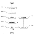
- FIG. 2 is a flowchart of the first embodiment
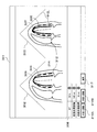
- FIG. 3 is a diagram illustrating a display example of the output / display unit 1 of the first embodiment.
- control unit 6 displays on the display screen of the output / display unit 1 an ultrasonic image depicting the target biological tissue (S101).
- left ventricular end-diastolic ultrasound image 302 and the end-systolic ultrasound image 303 are displayed side by side for the purpose of left ventricular volume measurement and EF measurement as shown in the display screen 301 of FIG. 3 will be described.
- the examiner sets multidimensional information (here, “contour line”) in the input unit 2, or the control unit 6 automatically sets a contour line by a multidimensional information automatic setting program stored in the storage unit 5. It may be set (S102).
- the setting of the contour line will be described with reference to the drawings.
- the target site is the heart
- the left ventricular end-diastolic contour 304 and the end systolic contour 305 are defined with respect to the heart.
- control unit 6 causes the measurement calculation unit 3 to perform the following calculation of the set lengths of the contour lines 304 and 305 and the distance between the lines (S103).
- the multidimensional information is a point instead of the outline 304 or 305, the coordinates of the point and the distance between the points may be calculated. If the multidimensional information is a region, the area and volume of the region are calculated. May be. As an area calculation method, there is a method of approximating an ellipse or a rectangle.
- the Simpson method is used in the first embodiment.
- the contour calculation described above is stored as a program in the storage unit 5 and is called at the time of measurement calculation.
- control unit 6 displays the calculated value of the contour calculated by the measurement calculation unit 3 on the screen of the output / display unit 7 (S104). There are the following three display forms of calculated values.
- First display form Specific examples of the display of the measurement values calculated by the measurement calculation unit 3 include an EF value 308A, an end-diastolic volume 308B, an end-systolic volume 308C, an end-diastolic axis length 308D, as shown in FIG.
- the end systolic axis length 308E is displayed numerically.
- the control unit 6 refers to the region of the target part on the display screen 301 to obtain the EF value. For example, the control unit 6 calculates the EF value using the volume of the part surrounded by the contour line 304 of the end-diastolic left ventricle and the volume of the part surrounded by the contour line 305 of the end-systolic left ventricle, and displays the calculated display as EF. It may be displayed on the screen as the value 308A.
- the control part 6 graphs the time change of the area
- the control unit 6 may calculate the left ventricular volume in each frame of the ultrasound image frame of one cardiac cycle, and create the graph 309 with respect to the time change of the left ventricular volume.
- the maximum volume value 310 may be used to divide the minimum volume value 311.
- FIG. 3 shows an example in which all of the first to third display forms are displayed, but any display form that is at least one of the first to third display forms may be used.
- the display mode of a measured value illustrates an EF value.
- the examiner checks whether or not the EF value on the display screen of the output / display unit 1 is appropriate, and inputs appropriate (OK) and inappropriate (NG) to the input unit 2 (S105).
- the control unit 6 receives an OK input from the input unit 2 and ends a series of measurement processes. Further, the control unit 6 receives an NG input from the input unit 2 and proceeds to a measurement value re-input process (S106).
- the examiner appropriately re-enters the EF value using the input unit 2 while confirming the calculation process of the EF value 308A displayed on the display screen 301 and the first to third display forms (S106). .
- re-inputting the EF value are that the examiner presses the measured value re-input switch 313 displayed on the screen to fine-tune the numerical value, or the examiner inputs the EF value directly using the keyboard. Or you may.
- the control unit 6 has a function of fixing and controlling variables contributing to the contour recalculation as exemplified below when the contour is recalculated based on the re-input EF value. .
- the examiner depresses the shaft length fixing switch 316D, and the contour portion is deformed by changing the diameter length with the shaft length unchanged.
- the axial length is the length of a line segment 306 indicating an axis extending from the midpoint 312A of the annulus to the apex 312B in the left ventricle.
- the examiner presses the fixed diameter switch 316E, makes the length of the diameter of the elliptic cylinder in the Simpson method unchanged, and changes the axial length to deform the contour portion.
- the examiner presses the uniform deformation switch 316H and changes the axial length and the radial length uniformly to deform the contour portion.
- control unit 6 may be provided not only with direct re-input of the numerical value of the EF value desired to be re-input, but also with a contour line correction direction designation switch for setting the contour line inside or outside the left ventricular contour.
- a contour line correction direction designation switch for setting the contour line inside or outside the left ventricular contour.
- an adjustment switch 316A is provided on the inside
- an adjustment switch 316B is provided on the outside. Then, the re-input result of the contour line moved to the adjustment switch 316A inward or the adjustment switch 316B outward is linked to the remeasurement calculation unit 4.
- the outline is adjusted to the outside, and the EF value 308A, end-diastolic volume 308B, and end-systolic volume 308C that are calculated at that time increase sequentially. Displayed.
- the amount of movement and the movement method are preliminarily set. You may make it set.
- control unit 6 causes the remeasurement calculation unit 4 to calculate the movement amount of the contour line based on the re-input amount of the EF value (S107).
- the examiner re-enters the EF value
- the EF value is calculated by the equation (1).
- the following equation (2) is shown.
- Vd is the end-diastolic volume
- Vs is the end-systolic volume.
- Re-inputting the EF value means adding the EF value to be re-input as a ⁇ EF value.
- the end-diastolic volume Vd and the end-systolic volume Vs change by the re-input end-diastolic volume ⁇ Vd and the re-input end-systolic volume ⁇ Vs as shown on the right side of the equation (2). That is, the measurement calculation unit 3 calculates using the re-input end-diastolic volume ⁇ Vd and the re-input end-systolic volume ⁇ Vs when the ⁇ EF value is given.
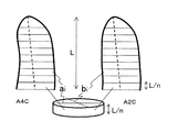
- FIG. 4 is a diagram for explaining the principle when the Simpson method is used to calculate the re-input volume ⁇ V.
- the apical four-chamber image (abbreviated as “A4C image”) and the apical two-chamber image (abbreviated as “A2C image”) are orthogonal to each other. Furthermore, the distance between the wall surfaces facing each other in the direction perpendicular to the axial length L is the length of the first diameter (abbreviated as ⁇ first diameter length '') ai, the length of the second diameter ( ⁇ An elliptic cylinder is assumed, where bi is abbreviated as “second diameter length” and the height is a distance L / n obtained by dividing the axial length into n equal parts (n is an integer greater than 1).
- the heart chamber volume V is calculated as shown in Equation (3) by determining the respective volumes of n elliptical cylinders and adding the determined volumes. Further, the first diameter length and the second diameter length are collectively referred to as a diameter length.
- the shaft length L, the first diameter length ai, and the second diameter length bi change by the re-input shaft length ⁇ L, the re-input first diameter length ⁇ ai, and the re-input second diameter length ⁇ bi. That is, the re-input volume ⁇ V can be calculated using the re-input shaft length ⁇ L, the re-input first diameter length ⁇ ai, and the re-input second diameter length ⁇ bi.
- FIG. 5 is a diagram for explaining an example of a method for changing the position of the contour line.
- FIG. 5 (a) shows the contour before change.
- the dotted line shows the contour line before the change, and the solid line shows the contour line after the change.
- the controller 6 changes the first diameter length ai to ai + ⁇ ai and changes the second diameter length bi to bi + ⁇ bi.
- Fig. 5 (b) is useful for the contour re-entry method that places importance on the axial length error. Because, it is recommended that the error between the A4C axis length and the A2C axis length be within 10% in heart volume measurement by the Simpson method, so the contour line shown in Fig. 5 (b) is re-input. This is because the method is preferable.
- the dotted line indicates the contour before the change
- the solid line indicates the contour after the change.
- the examiner first presses the diameter length fixing switch 316E in FIG.
- Fig. 5 (c) is useful for the contour re-entry method that places emphasis on error in diameter. This is because the movement of the subject's heart varies from person to person, and in many cases, it is sufficient to deal with errors in the axial length direction, but Fig. 5 (c) shows subjects who must emphasize error in the radial direction. This is because it is suitable as a method for re-inputting the contour line.
- FIG. 5 (d) As in FIG. 5 (b), the dotted line indicates the contour before the change, and the solid line indicates the contour after the change.
- the operation before and after the change of the contour line in FIG. 5 (d) will be described.
- the control unit 6 changes all of the shaft length L, the first diameter length ai, and the second diameter length bi.
- FIG. 5 (d) it is assumed that the values of the re-input shaft length ⁇ L, half of the re-input first diameter length ( ⁇ ai / 2), and half of the re-input second diameter length ( ⁇ bi / 2) are the same. Will be calculated.
- the axial length and the radial length are changed almost uniformly.
- Fig. 5 (d) is useful for the contour re-entry method that equalizes the axial length and diameter length errors. This is because if it is difficult to re-enter the contour line even if the individual difference in the heart movement of the subject is focused on the axial length error (Fig. 5 (b)) and the radial length error is emphasized (Fig. 5 (c)), Fig. 5 This is because (d) is suitable as a method for re-inputting the contour line to the subject with uniform axial length and radial length errors.
- the re-input range setting switch 601 in FIG. 6 may be pressed to set the upper limit value and lower limit value of the re-input amount such as the EF value 308A.
- FIG. 6 is a diagram showing a display example different from FIG. 3 of the screen of the first embodiment.
- the re-input range of the EF value 308A is set in advance as shown in the display area 602 so that the re-input amount of the EF value 308A is within ⁇ 10%, and the re-input amount of the end-diastolic volume 308B and end-systolic volume 308C is within ⁇ 20 ml.
- the control unit 6 displays a warning on the output / display unit 1 when a re-input exceeding the set re-input range is applied.
- warning display is “Message (abbreviated as“ MSG ”): Exceeding EF value re-input range, as shown in display area 602 of screen 301 of output / display unit 1. Please check this. Or a warning text such as “” is displayed, or the numerical value of the EF value 308A that has reached the limit value is displayed in color.
- FIG. 6 is useful for alerting the examiner to a re-input operation that exceeds the allowable re-input range for the contour line.
- S106, S107, S103, S104, and S105 can be repeated until it becomes unnecessary to input again.
- Example 1 there is an effect of providing a medical image diagnostic apparatus having a function for re-inputting multidimensional information and measurement values of an organ region of a subject and a method for re-inputting measurement values of a medical image. Further, the unique effect of Example 1 is that, in the volume calculation method by the Simpson method, whether or not to adjust one or both of the axial length and the radial length can be arbitrarily selected by the examiner, and partly multidimensional information. There is an effect that (contour line) can be changed.
- Example 2 is that the area / length method is used instead of the Simpson method used in Example 1 in the re-input multidimensional information calculation (S107) of Example 1.
- FIG. 7 is a diagram illustrating the principle of calculating the re-input volume ⁇ V using the area / length method of the second embodiment.
- the area / length method uses the area A surrounded by the contour lines 304 and 305 shown in FIG. 3 and the axial length L extending from the midpoint between the annulus 312 to the apex to express the left ventricle using Equation (5). Calculate the volume V.
- the volume V of the left ventricle is obtained by adding the volume change amount ⁇ V to Equation (6).
- the re-input portions of the area A and the axial length L are set as a re-input area ⁇ A and a re-input shaft length ⁇ L, respectively.
- ⁇ V is calculated using the re-input area ⁇ A and the re-input shaft length ⁇ L.
- FIG. 7 is a diagram showing an example in which the positions of the contour lines 304 and 305 are changed by conditioning.
- FIG. 7 (a) shows the contour before the change.
- FIG. 7B shows an example in which the shaft length is fixed by the shaft length fixing switch 316D.
- the contour line 304 or the contour line 305 is moved so that the axis L does not change as shown in FIG.
- FIG. 7 (c) shows an example in which the area and the axial length are variable. In this case, it is selected when a switch such as the shaft length fixing switch 316D is not pressed.
- the control unit 6 schematically displays part (c) of FIG.
- the re-input volume ⁇ V is calculated using the re-input area ⁇ A and the re-input shaft length ⁇ L set in this way in Expression (6) (S107).
- Example 2 there is an effect of providing a medical image diagnostic apparatus having a function of re-inputting multidimensional information and measurement values of an organ region of a subject and a method for re-inputting measurement values of a medical image.
- the specific effect of Example 2 is that the examiner can arbitrarily select whether to adjust the axial length or both the axial length and the area in the volume calculation method by the area / length method.
- multidimensional information (contour line) can be changed.
- Example 3 is that the re-input multidimensional information calculation (S107) of Example 1 uses a different axial length calculation method in the Simpson method used in Example 1. Hereinafter, only the calculation method of S107 that is different from the first embodiment will be described.
- Fig. 8 is a diagram showing a method for changing the axial lengths of A4C and A2C.
- the error between the A4C axis length and the A2C axis length be within 10%.
- these axial lengths may be re-entered into the recommended error range.
- the re-input method is as follows.
- the examiner uses the mouse provided in the input unit 2 to press the axis length error re-input switch 316G and finely adjust the numerical value as shown in FIG.
- An EF value may be directly input using a provided keyboard.
- FIG. 9 shows an example of a screen that displays the measurement result of the third embodiment.
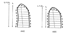
- the control unit 6 receives the input value using the input unit 2 and re-inputs the axial length L to L + ⁇ L.
- the formula (4 ) Or (6) can be conditioned.
- an outline is shown when the axial length is changed by ⁇ L under the condition of fixed volume.
- a broken line is an outline before change, and a solid line is an outline after change.
- the axis length error re-input switch 316G described above has a ⁇ L so that the axis length error of the A4C and A2C is within 10% only by receiving the input from the examiner's input unit 2.
- the calculation position remeasurement calculation unit 4 and the measurement calculation unit 3 may be controlled to automatically adjust (S107).
- the third embodiment described above there is an effect of providing a medical image diagnostic apparatus having a function for re-inputting multidimensional information and measurement values of an organ region of a subject and a method for re-inputting measurement values of a medical image. Further, the unique effect of the third embodiment is that it is possible to automatically correct the difference between the axial lengths of A4C and A2C in the EF value measurement, thereby reducing the burden of manual re-input by the examiner.
- Example 4 is an example in which the examiner inputs the re-input EF value into the display field of the EF value 308A using the input unit 2, and sets a contour line superimposed on the ultrasound image according to the input EF value. explain.
- the difference between the fourth embodiment and the first embodiment is that the measurement value setting (S201) is inserted into the ultrasonic image display (S101) and the multidimensional information setting (S102) of the living tissue. Since the description other than the differences is the same as that of the first embodiment, only the differences will be described.
- FIG. 10 is a flowchart illustrating the operation procedure of the fourth embodiment.
- the examiner uses the input unit 2 to set a desired EF value in the EF value list 308A in FIG. 3 while viewing the ultrasonic image displayed in S101 (S201).
- the control unit 6 performs re-input multidimensional information calculation (S107) so that the EF value set in S201 is calculated. Thereafter, the measurement setting position is displayed on the screen (S104). The result is confirmed (S105), and if re-input is necessary, the examiner operates the input unit 2 to re-input the EF value (S106).
- the fourth embodiment it is possible to provide a medical image diagnostic apparatus having a function for re-inputting multidimensional information and measurement values of an organ region of a subject and a method for re-inputting measurement values of a medical image.
- the specific effect of Example 4 is that the desired EF value can be set at the initial stage of processing. Therefore, when the EF value is predicted in advance, it is set to the expected EF value first. Then, it is possible to set multidimensional information (outline) in the next re-input procedure.
- Example 5 is a method of presenting a plurality of re-input contour candidates in the measurement result display (S104) of Example 1 so that the examiner can select one of the plurality of presented candidates. Only the measurement result display (S104) related to re-input multidimensional information and screen display different from the first embodiment will be described.
- FIG. 11 shows an example of a screen that displays the measurement result of the fifth embodiment.
- an outline having an EF value of 50% is displayed in the left column.
- ultrasonic images of 46%, 48%, and 52% with an EF value of around 50% are arranged in order.
- a portion where an ultrasonic image having an EF value of 50% is inserted is denoted by reference numeral 1101.
- each contour line (S107).
- each contour line having EF values of 46%, 48%, and 52% is calculated.
- FIG. 11 is a screen that displays contour lines for a plurality of EF values.
- the upper ultrasonic image is an end-diastolic ultrasonic image
- the lower ultrasonic image is an end-systolic ultrasonic image.
- the examiner visually recognizes and selects the optimum contour line while viewing the ultrasound image on which the contour line of each ultrasound image is displayed (S105).
- the examiner suspects that the EF value is 50% or less and is within the normal range if the EF value exceeds 50%, the examiner will comprehensively analyze the end-diastolic and end-systolic movements of the heart. Thus, it is possible to confirm the normal range or the suspicion of the disease.
- the fifth embodiment it is possible to provide a medical image diagnostic apparatus having a function for re-inputting multidimensional information and measurement values of an organ region of a subject and a method for re-inputting measurement values of a medical image. Further, the unique effect of the fifth embodiment is that it is possible to provide judgment information for diagnosis that integrates the movement of the heart at the end of expansion and the movement of the end systole. Further, the examiner can select the optimum multidimensional information (contour line) and EF value while observing the change of the multidimensional information (contour line) with respect to the minute change of the EF value.
- Example 6 is a modification of the measurement result display (S104) of Example 5, and is an example in which an A2C image is referred to and displayed on an A4C image. Only the measurement result display (S104) related to contour re-input and screen display, which is different from the fifth embodiment, will be described.
- FIG. 12 is a diagram illustrating an example of a screen that displays the measurement result of the sixth embodiment.
- the leftmost ultrasonic image 302 and ultrasonic image 303 in FIG. 12 are A4C images when the EF value is set to 50%.
- An A2C image is displayed on the right side of the ultrasonic image 302 and the ultrasonic image 303.
- the upper row is an ultrasonic image at the end diastole and the lower row is an ultrasonic image at the end systole.
- the A4C image and the A2C image are orthogonal to each other, it has the same meaning as displaying the elliptical cylinders stacked using the diameters of each other in three dimensions.
- A4C images with an EF value of 50% are displayed.
- an A4C image is shown, but it may be A2C.
- the examiner selects and confirms the optimum contour line while viewing the contour line displayed in three dimensions (S105).
- the sixth embodiment described above there is an effect of providing a medical image diagnostic apparatus having a function for re-inputting multidimensional information and measurement values of an organ region of a subject and a method for re-inputting measurement values of a medical image.
- the A4C image and the A2C image display an ultrasonic image in a positional relationship in which the A4C image and the A2C image are orthogonal to each other, multidimensional information (contour lines) can be re-input based on the three-dimensional information. There is an effect.
- the seventh embodiment presents a plurality of candidates for a re-input contour line on the same ultrasonic image so that the examiner can select one of the plurality of presented candidates. It is a method to do. Only the measurement result display (S104) related to contour re-input and screen display, which is different from the first embodiment, will be described.
- FIG. 13 illustrates an example of a screen that displays a plurality of measurement results according to the seventh embodiment.
- Dashed lines (304, 305) indicate contours with an EF value of 50%. On the outside of the contour line, a contour line of 52% of the EF value is indicated by a solid line.
- the outline of EF48% is shown as a solid line inside the outline of EF value 50%.
- the examiner selects and confirms the optimum contour line while viewing the plurality of contour line candidates displayed simultaneously (S105).
- the display method of the contour line is displayed by changing the line type, but the color of the contour line is changed, or different contour lines are blinked, that is, the display is different among a plurality of contour lines. Any mode may be used.
- a two-dimensional contour line is shown as an example in FIG. 13, but a three-dimensional contour line may be displayed as in the sixth embodiment.
- the seventh embodiment described above there is an effect of providing a medical image diagnostic apparatus having a function for re-inputting multidimensional information and measurement values of an organ region of a subject and a method for re-inputting measurement values of a medical image.
- the unique effect of the seventh embodiment is to display one ultrasonic image, only two image displays of the end-diastolic and end-systolic ultrasonic images are sufficient, and thus a plurality of examples such as the fifth embodiment
- comparative display of multidimensional information can be performed with a smaller number of display screens.
- Example 8 is a method of displaying a normal outline as the current outline in the measurement result display (S104) of Example 1 so that the treatment progress can be observed.
- the eighth embodiment only the measurement result display (S104) related to contour re-input and screen display, which is different from the first embodiment, will be described.
- the end systolic volume increases and the EF value decreases.
- This may be treated with drugs or the like to reduce the end systolic volume and increase the EF value.
- using the current contour line calculate the contour line when the healthy volume and EF value are reached, and display these contour lines on the screen, the difference between the current heart and the healthy heart It becomes easy to understand the figure.
- FIG. 14 illustrates an example of a screen that displays a plurality of measurement results according to the eighth embodiment.
- FIG. 14 shows a contour line (broken line) for the EF value of the lesion and a contour line (solid line) for the healthy EF value.
- the solid line of the contour line for the EF value of the lesion is displayed.
- Normal values of healthy volume values and EF values are stored in the storage unit 5 in advance.
- the control unit 6 reads the standard value and calculates the contour line of the standard value.
- the outline of the standard value is, for example, an average value of a number of healthy cases, or a value that the target patient should target.
- control unit 6 may store values and contour lines measured in at least one past inspection in the storage unit 5 and superimpose these data on the current inspection screen. Thereby, it is possible to display the continuous treatment process from the past examination to the current examination in an easily understandable manner.
- Example 8 it is possible to provide a medical image diagnostic apparatus having a function for re-inputting multi-dimensional information and measurement values of an organ region of a subject and a method for re-inputting a measurement value of a medical image.
- the unique effect of Example 8 is that it is possible to display the continuous treatment process from the past examination to the current examination in an easily understandable manner.
- the above is an example of measuring a heart in an ultrasonic diagnostic apparatus, but the present invention can be similarly applied to other diagnostic apparatuses and biological tissues.
Landscapes
- Health & Medical Sciences (AREA)
- Life Sciences & Earth Sciences (AREA)
- Engineering & Computer Science (AREA)
- Physics & Mathematics (AREA)
- Public Health (AREA)
- Medical Informatics (AREA)
- General Health & Medical Sciences (AREA)
- Biomedical Technology (AREA)
- Pathology (AREA)
- Heart & Thoracic Surgery (AREA)
- Biophysics (AREA)
- Molecular Biology (AREA)
- Surgery (AREA)
- Animal Behavior & Ethology (AREA)
- Veterinary Medicine (AREA)
- Radiology & Medical Imaging (AREA)
- Nuclear Medicine, Radiotherapy & Molecular Imaging (AREA)
- Computer Vision & Pattern Recognition (AREA)
- Physiology (AREA)
- Dentistry (AREA)
- Oral & Maxillofacial Surgery (AREA)
- Geometry (AREA)
- General Physics & Mathematics (AREA)
- Theoretical Computer Science (AREA)
- Human Computer Interaction (AREA)
- Data Mining & Analysis (AREA)
- Databases & Information Systems (AREA)
- Epidemiology (AREA)
- Primary Health Care (AREA)
- Ultra Sonic Daignosis Equipment (AREA)
Abstract
Priority Applications (4)
| Application Number | Priority Date | Filing Date | Title |
|---|---|---|---|
| US13/634,723 US20130012835A1 (en) | 2010-03-31 | 2011-03-24 | Ultrasonic diagnostic apparatus and method for re-inputting measurement value of medical image |
| CN201180015874.9A CN102821698B (zh) | 2010-03-31 | 2011-03-24 | 医用图像诊断装置以及医用图像的测量值再输入方法 |
| EP11765414.5A EP2554123A4 (fr) | 2010-03-31 | 2011-03-24 | Dispositif de diagnostic d'image médicale, et procédé de réentrée de valeurs mesurées d'image médicale |
| JP2012509426A JP5738279B2 (ja) | 2010-03-31 | 2011-03-24 | 医用画像診断装置及び、医用画像の計測値再入力方法 |
Applications Claiming Priority (2)
| Application Number | Priority Date | Filing Date | Title |
|---|---|---|---|
| JP2010-080144 | 2010-03-31 | ||
| JP2010080144 | 2010-03-31 |
Publications (1)
| Publication Number | Publication Date |
|---|---|
| WO2011125513A1 true WO2011125513A1 (fr) | 2011-10-13 |
Family
ID=44762467
Family Applications (1)
| Application Number | Title | Priority Date | Filing Date |
|---|---|---|---|
| PCT/JP2011/057134 Ceased WO2011125513A1 (fr) | 2010-03-31 | 2011-03-24 | Dispositif de diagnostic d'image médicale, et procédé de réentrée de valeurs mesurées d'image médicale |
Country Status (5)
| Country | Link |
|---|---|
| US (1) | US20130012835A1 (fr) |
| EP (1) | EP2554123A4 (fr) |
| JP (1) | JP5738279B2 (fr) |
| CN (1) | CN102821698B (fr) |
| WO (1) | WO2011125513A1 (fr) |
Cited By (7)
| Publication number | Priority date | Publication date | Assignee | Title |
|---|---|---|---|---|
| WO2013146710A1 (fr) * | 2012-03-30 | 2013-10-03 | 株式会社東芝 | Équipement de diagnostic ultrasonore, dispositif de traitement d'image et procédé de traitement d'image |
| JP2017121520A (ja) * | 2012-03-30 | 2017-07-13 | 東芝メディカルシステムズ株式会社 | 超音波診断装置、画像処理装置及び画像処理方法 |
| JP2019115559A (ja) * | 2017-12-27 | 2019-07-18 | キヤノンメディカルシステムズ株式会社 | 超音波診断装置及び画像処理プログラム |
| JP2020171427A (ja) * | 2019-04-09 | 2020-10-22 | コニカミノルタ株式会社 | 動態画像解析装置、動態画像解析システム及びプログラム |
| JP2022509453A (ja) * | 2018-10-26 | 2022-01-20 | フィリップス イメージ ガイディッド セラピー コーポレイション | 管腔内超音波血管境界の選択並びに関連するデバイス、システム、および方法 |
| JP2022158712A (ja) * | 2021-04-02 | 2022-10-17 | キヤノンメディカルシステムズ株式会社 | 超音波診断装置、画像処理装置、及び画像処理プログラム |
| JP2022172765A (ja) * | 2021-05-07 | 2022-11-17 | キヤノンメディカルシステムズ株式会社 | 医用画像処理装置、超音波診断装置、およびプログラム |
Families Citing this family (12)
| Publication number | Priority date | Publication date | Assignee | Title |
|---|---|---|---|---|
| EP2554123A4 (fr) * | 2010-03-31 | 2016-01-27 | Hitachi Medical Corp | Dispositif de diagnostic d'image médicale, et procédé de réentrée de valeurs mesurées d'image médicale |
| CN102920477B (zh) * | 2012-03-05 | 2015-05-20 | 杭州弘恩医疗科技有限公司 | 医学影像的目标区域边界确定装置和方法 |
| JP6228969B2 (ja) * | 2013-03-29 | 2017-11-08 | 株式会社日立製作所 | 医療用診断装置およびその計測方法 |
| US20170164924A1 (en) * | 2015-12-15 | 2017-06-15 | Konica Minolta, Inc. | Ultrasound image diagnostic apparatus |
| JP6987558B2 (ja) * | 2016-08-10 | 2022-01-05 | キヤノンメディカルシステムズ株式会社 | 医用処理装置、超音波診断装置および医用処理プログラム |
| EP3287915B1 (fr) * | 2016-08-25 | 2023-11-08 | Siemens Healthcare GmbH | Generation d'une quantite de favoris comprenant plusieurs protocoles destines a commander un appareil d'imagerie |
| EP3673814B1 (fr) * | 2017-08-23 | 2022-11-16 | FUJIFILM Corporation | Appareil de diagnostic à onde acoustique et procédé de commande d'un appareil de diagnostic à onde acoustique |
| CN112584738B (zh) * | 2018-08-30 | 2024-04-23 | 奥林巴斯株式会社 | 记录装置、图像观察装置、观察系统、观察系统的控制方法及存储介质 |
| JP7328156B2 (ja) * | 2020-01-22 | 2023-08-16 | キヤノンメディカルシステムズ株式会社 | 超音波診断装置、医用画像処理装置、および医用画像処理プログラム |
| US12262153B2 (en) | 2020-04-30 | 2025-03-25 | Medtronic, Inc. | Post operative implantation site monitoring |
| US12260555B2 (en) * | 2020-04-30 | 2025-03-25 | Medtronic, Inc. | Post operative implantation site monitoring and medical device performance |
| CN120551663B (zh) * | 2025-07-31 | 2025-10-24 | 常州坤维传感科技有限公司 | 一种适用于多维力传感器的焊接方法及系统 |
Citations (7)
| Publication number | Priority date | Publication date | Assignee | Title |
|---|---|---|---|---|
| JPH0199328A (ja) | 1987-10-13 | 1989-04-18 | Fujitsu Ltd | 送信出力制御方式 |
| JP2002224116A (ja) * | 2001-01-31 | 2002-08-13 | Matsushita Electric Ind Co Ltd | 超音波診断装置及び画像処理装置 |
| JP2004254829A (ja) * | 2003-02-25 | 2004-09-16 | Hitachi Medical Corp | 超音波診断装置 |
| JP2007507248A (ja) | 2003-09-29 | 2007-03-29 | コーニンクレッカ フィリップス エレクトロニクス エヌ ヴィ | 超音波による心臓ボリューム数量化方法 |
| JP2007117344A (ja) * | 2005-10-27 | 2007-05-17 | Aloka System Engineering Co Ltd | 超音波診断装置及び超音波画像処理方法 |
| JP2008012047A (ja) * | 2006-07-05 | 2008-01-24 | Aloka Co Ltd | 超音波診断装置 |
| JP2008104695A (ja) * | 2006-10-26 | 2008-05-08 | Toshiba Corp | 超音波診断装置、画像処理装置、及び画像処理プログラム |
Family Cites Families (9)
| Publication number | Priority date | Publication date | Assignee | Title |
|---|---|---|---|---|
| JP3205760B2 (ja) * | 1992-12-14 | 2001-09-04 | シャープ株式会社 | 輸液装置 |
| JP3455027B2 (ja) * | 1996-09-10 | 2003-10-06 | 株式会社日立メディコ | X線画像表示装置 |
| US6226542B1 (en) * | 1998-07-24 | 2001-05-01 | Biosense, Inc. | Three-dimensional reconstruction of intrabody organs |
| US6447453B1 (en) * | 2000-12-07 | 2002-09-10 | Koninklijke Philips Electronics N.V. | Analysis of cardiac performance using ultrasonic diagnostic images |
| JP2005021573A (ja) * | 2003-07-02 | 2005-01-27 | Canon Inc | 画像撮影装置及びその設定管理方法並びにデータ管理プログラム |
| US7559896B2 (en) * | 2004-08-27 | 2009-07-14 | General Electric Company | Physiological definition user interface |
| US7822246B2 (en) * | 2004-12-20 | 2010-10-26 | Koninklijke Philips Electronics N.V. | Method, a system and a computer program for integration of medical diagnostic information and a geometric model of a movable body |
| US7849024B2 (en) * | 2006-08-16 | 2010-12-07 | Drvision Technologies Llc | Imaging system for producing recipes using an integrated human-computer interface (HCI) for image recognition, and learning algorithms |
| EP2554123A4 (fr) * | 2010-03-31 | 2016-01-27 | Hitachi Medical Corp | Dispositif de diagnostic d'image médicale, et procédé de réentrée de valeurs mesurées d'image médicale |
-
2011
- 2011-03-24 EP EP11765414.5A patent/EP2554123A4/fr not_active Withdrawn
- 2011-03-24 WO PCT/JP2011/057134 patent/WO2011125513A1/fr not_active Ceased
- 2011-03-24 US US13/634,723 patent/US20130012835A1/en not_active Abandoned
- 2011-03-24 CN CN201180015874.9A patent/CN102821698B/zh not_active Expired - Fee Related
- 2011-03-24 JP JP2012509426A patent/JP5738279B2/ja not_active Expired - Fee Related
Patent Citations (7)
| Publication number | Priority date | Publication date | Assignee | Title |
|---|---|---|---|---|
| JPH0199328A (ja) | 1987-10-13 | 1989-04-18 | Fujitsu Ltd | 送信出力制御方式 |
| JP2002224116A (ja) * | 2001-01-31 | 2002-08-13 | Matsushita Electric Ind Co Ltd | 超音波診断装置及び画像処理装置 |
| JP2004254829A (ja) * | 2003-02-25 | 2004-09-16 | Hitachi Medical Corp | 超音波診断装置 |
| JP2007507248A (ja) | 2003-09-29 | 2007-03-29 | コーニンクレッカ フィリップス エレクトロニクス エヌ ヴィ | 超音波による心臓ボリューム数量化方法 |
| JP2007117344A (ja) * | 2005-10-27 | 2007-05-17 | Aloka System Engineering Co Ltd | 超音波診断装置及び超音波画像処理方法 |
| JP2008012047A (ja) * | 2006-07-05 | 2008-01-24 | Aloka Co Ltd | 超音波診断装置 |
| JP2008104695A (ja) * | 2006-10-26 | 2008-05-08 | Toshiba Corp | 超音波診断装置、画像処理装置、及び画像処理プログラム |
Non-Patent Citations (1)
| Title |
|---|
| See also references of EP2554123A4 * |
Cited By (16)
| Publication number | Priority date | Publication date | Assignee | Title |
|---|---|---|---|---|
| WO2013146710A1 (fr) * | 2012-03-30 | 2013-10-03 | 株式会社東芝 | Équipement de diagnostic ultrasonore, dispositif de traitement d'image et procédé de traitement d'image |
| JP2013226400A (ja) * | 2012-03-30 | 2013-11-07 | Toshiba Corp | 超音波診断装置、画像処理装置及び画像処理方法 |
| CN103648402A (zh) * | 2012-03-30 | 2014-03-19 | 株式会社东芝 | 超声波诊断装置、图像处理装置以及图像处理方法 |
| CN103648402B (zh) * | 2012-03-30 | 2016-06-22 | 株式会社东芝 | 超声波诊断装置、图像处理装置以及图像处理方法 |
| JP2017121520A (ja) * | 2012-03-30 | 2017-07-13 | 東芝メディカルシステムズ株式会社 | 超音波診断装置、画像処理装置及び画像処理方法 |
| JP7009205B2 (ja) | 2017-12-27 | 2022-01-25 | キヤノンメディカルシステムズ株式会社 | 超音波診断装置及び画像処理プログラム |
| JP2019115559A (ja) * | 2017-12-27 | 2019-07-18 | キヤノンメディカルシステムズ株式会社 | 超音波診断装置及び画像処理プログラム |
| JP2022509453A (ja) * | 2018-10-26 | 2022-01-20 | フィリップス イメージ ガイディッド セラピー コーポレイション | 管腔内超音波血管境界の選択並びに関連するデバイス、システム、および方法 |
| JP7299992B2 (ja) | 2018-10-26 | 2023-06-28 | フィリップス イメージ ガイディッド セラピー コーポレイション | 管腔内超音波血管境界の選択並びに関連するデバイス、システム、および方法 |
| JP2020171427A (ja) * | 2019-04-09 | 2020-10-22 | コニカミノルタ株式会社 | 動態画像解析装置、動態画像解析システム及びプログラム |
| JP7255329B2 (ja) | 2019-04-09 | 2023-04-11 | コニカミノルタ株式会社 | 動態画像解析装置、動態画像解析システム及びプログラム |
| JP2022158712A (ja) * | 2021-04-02 | 2022-10-17 | キヤノンメディカルシステムズ株式会社 | 超音波診断装置、画像処理装置、及び画像処理プログラム |
| JP7716873B2 (ja) | 2021-04-02 | 2025-08-01 | キヤノンメディカルシステムズ株式会社 | 超音波診断装置、画像処理装置、及び画像処理プログラム |
| JP2022172765A (ja) * | 2021-05-07 | 2022-11-17 | キヤノンメディカルシステムズ株式会社 | 医用画像処理装置、超音波診断装置、およびプログラム |
| JP7780875B2 (ja) | 2021-05-07 | 2025-12-05 | キヤノンメディカルシステムズ株式会社 | 医用画像処理装置、超音波診断装置、およびプログラム |
| US12597125B2 (en) | 2021-05-07 | 2026-04-07 | Canon Medical Systems Corporation | Apparatus and method for correcting a contour of an object in a medical image |
Also Published As
| Publication number | Publication date |
|---|---|
| US20130012835A1 (en) | 2013-01-10 |
| CN102821698A (zh) | 2012-12-12 |
| JP5738279B2 (ja) | 2015-06-24 |
| EP2554123A1 (fr) | 2013-02-06 |
| JPWO2011125513A1 (ja) | 2013-07-08 |
| EP2554123A4 (fr) | 2016-01-27 |
| CN102821698B (zh) | 2015-05-20 |
Similar Documents
| Publication | Publication Date | Title |
|---|---|---|
| JP5738279B2 (ja) | 医用画像診断装置及び、医用画像の計測値再入力方法 | |
| US20220233172A1 (en) | Ultrasound diagnosis apparatus and method for generating image from volume data and displaying the same | |
| CN101147687B (zh) | 超声波图像取得装置、超声波图像显示方法及医疗装置 | |
| CN103648402B (zh) | 超声波诊断装置、图像处理装置以及图像处理方法 | |
| JP6495003B2 (ja) | 医用画像処理装置、医用画像診断装置及び医用画像処理方法 | |
| CN105025806B (zh) | 医用图像诊断装置、医用图像处理装置以及医用图像处理方法 | |
| US20180008232A1 (en) | Ultrasonic diagnostic apparatus, scan support method, and medical image processing apparatus | |
| EP2916285B1 (fr) | Appareil de traitement d'image médicale et procédé de traitement d'image médicale en utilisant l'appareil | |
| US20110118590A1 (en) | System For Continuous Cardiac Imaging And Mapping | |
| JP6207819B2 (ja) | 画像処理装置、x線診断装置及びプログラム | |
| US10736608B2 (en) | Ultrasound diagnostic device and ultrasound image processing method | |
| EP2989987B1 (fr) | Appareil de diagnostic à ultrasons et procédé et support de stockage lisible par ordinateur | |
| JP7804395B2 (ja) | 生体信号処理システムを備えた医用画像撮像装置、医用撮像システム、及び生体信号処理方法 | |
| US12053327B2 (en) | Devices, systems, and methods for guiding repeated ultrasound exams for serial monitoring | |
| KR20150120214A (ko) | 의료 영상 장치 및 그 동작방법 | |
| JP2018079070A (ja) | 超音波診断装置、及び走査支援プログラム | |
| US20160302761A1 (en) | Ultrasound system for displaying stiffness of blood vessel | |
| JP5814655B2 (ja) | 医用画像診断装置 | |
| JP6964996B2 (ja) | 解析装置 | |
| EP4356844B1 (fr) | Appareil de diagnostic à ultrasons et procédé de commande d'appareil de diagnostic à ultrasons | |
| CN108371547A (zh) | X射线摄影装置和x射线图像分析方法 | |
| EP4356843A1 (fr) | Appareil de diagnostic à ultrasons et procédé de commande d'appareil de diagnostic à ultrasons | |
| US20100145188A1 (en) | Imaging diagnostic device, measurement point setting method, and program | |
| JP2013183996A (ja) | 心臓矯正ネットの製造方法 | |
| JP2004313513A (ja) | X線ct装置 |
Legal Events
| Date | Code | Title | Description |
|---|---|---|---|
| WWE | Wipo information: entry into national phase |
Ref document number: 201180015874.9 Country of ref document: CN |
|
| 121 | Ep: the epo has been informed by wipo that ep was designated in this application |
Ref document number: 11765414 Country of ref document: EP Kind code of ref document: A1 |
|
| WWE | Wipo information: entry into national phase |
Ref document number: 2012509426 Country of ref document: JP |
|
| WWE | Wipo information: entry into national phase |
Ref document number: 13634723 Country of ref document: US |
|
| WWE | Wipo information: entry into national phase |
Ref document number: 2011765414 Country of ref document: EP |
|
| NENP | Non-entry into the national phase |
Ref country code: DE |