WO2011126068A1 - 電解液注入装置及び電解液注入方法 - Google Patents
電解液注入装置及び電解液注入方法 Download PDFInfo
- Publication number
- WO2011126068A1 WO2011126068A1 PCT/JP2011/058784 JP2011058784W WO2011126068A1 WO 2011126068 A1 WO2011126068 A1 WO 2011126068A1 JP 2011058784 W JP2011058784 W JP 2011058784W WO 2011126068 A1 WO2011126068 A1 WO 2011126068A1
- Authority
- WO
- WIPO (PCT)
- Prior art keywords
- electrolyte
- decompression chamber
- battery case
- electrolytic solution
- aeration tank
- Prior art date
- Legal status (The legal status is an assumption and is not a legal conclusion. Google has not performed a legal analysis and makes no representation as to the accuracy of the status listed.)
- Ceased
Links
Images


Classifications
-
- H—ELECTRICITY
- H01—ELECTRIC ELEMENTS
- H01M—PROCESSES OR MEANS, e.g. BATTERIES, FOR THE DIRECT CONVERSION OF CHEMICAL ENERGY INTO ELECTRICAL ENERGY
- H01M50/00—Constructional details or processes of manufacture of the non-active parts of electrochemical cells other than fuel cells, e.g. hybrid cells
- H01M50/60—Arrangements or processes for filling or topping-up with liquids; Arrangements or processes for draining liquids from casings
- H01M50/609—Arrangements or processes for filling with liquid, e.g. electrolytes
- H01M50/618—Pressure control
-
- H—ELECTRICITY
- H01—ELECTRIC ELEMENTS
- H01M—PROCESSES OR MEANS, e.g. BATTERIES, FOR THE DIRECT CONVERSION OF CHEMICAL ENERGY INTO ELECTRICAL ENERGY
- H01M10/00—Secondary cells; Manufacture thereof
- H01M10/05—Accumulators with non-aqueous electrolyte
- H01M10/052—Li-accumulators
- H01M10/0525—Rocking-chair batteries, i.e. batteries with lithium insertion or intercalation in both electrodes; Lithium-ion batteries
-
- H—ELECTRICITY
- H01—ELECTRIC ELEMENTS
- H01M—PROCESSES OR MEANS, e.g. BATTERIES, FOR THE DIRECT CONVERSION OF CHEMICAL ENERGY INTO ELECTRICAL ENERGY
- H01M10/00—Secondary cells; Manufacture thereof
- H01M10/05—Accumulators with non-aqueous electrolyte
- H01M10/058—Construction or manufacture
- H01M10/0585—Construction or manufacture of accumulators having only flat construction elements, i.e. flat positive electrodes, flat negative electrodes and flat separators
-
- H—ELECTRICITY
- H01—ELECTRIC ELEMENTS
- H01M—PROCESSES OR MEANS, e.g. BATTERIES, FOR THE DIRECT CONVERSION OF CHEMICAL ENERGY INTO ELECTRICAL ENERGY
- H01M50/00—Constructional details or processes of manufacture of the non-active parts of electrochemical cells other than fuel cells, e.g. hybrid cells
- H01M50/60—Arrangements or processes for filling or topping-up with liquids; Arrangements or processes for draining liquids from casings
- H01M50/673—Containers for storing liquids; Delivery conduits therefor
-
- H—ELECTRICITY
- H01—ELECTRIC ELEMENTS
- H01M—PROCESSES OR MEANS, e.g. BATTERIES, FOR THE DIRECT CONVERSION OF CHEMICAL ENERGY INTO ELECTRICAL ENERGY
- H01M14/00—Electrochemical current or voltage generators not provided for in groups H01M6/00 - H01M12/00; Manufacture thereof
-
- H—ELECTRICITY
- H01—ELECTRIC ELEMENTS
- H01M—PROCESSES OR MEANS, e.g. BATTERIES, FOR THE DIRECT CONVERSION OF CHEMICAL ENERGY INTO ELECTRICAL ENERGY
- H01M2300/00—Electrolytes
-
- H—ELECTRICITY
- H01—ELECTRIC ELEMENTS
- H01M—PROCESSES OR MEANS, e.g. BATTERIES, FOR THE DIRECT CONVERSION OF CHEMICAL ENERGY INTO ELECTRICAL ENERGY
- H01M50/00—Constructional details or processes of manufacture of the non-active parts of electrochemical cells other than fuel cells, e.g. hybrid cells
- H01M50/70—Arrangements for stirring or circulating the electrolyte
-
- Y—GENERAL TAGGING OF NEW TECHNOLOGICAL DEVELOPMENTS; GENERAL TAGGING OF CROSS-SECTIONAL TECHNOLOGIES SPANNING OVER SEVERAL SECTIONS OF THE IPC; TECHNICAL SUBJECTS COVERED BY FORMER USPC CROSS-REFERENCE ART COLLECTIONS [XRACs] AND DIGESTS
- Y02—TECHNOLOGIES OR APPLICATIONS FOR MITIGATION OR ADAPTATION AGAINST CLIMATE CHANGE
- Y02E—REDUCTION OF GREENHOUSE GAS [GHG] EMISSIONS, RELATED TO ENERGY GENERATION, TRANSMISSION OR DISTRIBUTION
- Y02E60/00—Enabling technologies; Technologies with a potential or indirect contribution to GHG emissions mitigation
- Y02E60/10—Energy storage using batteries
-
- Y—GENERAL TAGGING OF NEW TECHNOLOGICAL DEVELOPMENTS; GENERAL TAGGING OF CROSS-SECTIONAL TECHNOLOGIES SPANNING OVER SEVERAL SECTIONS OF THE IPC; TECHNICAL SUBJECTS COVERED BY FORMER USPC CROSS-REFERENCE ART COLLECTIONS [XRACs] AND DIGESTS
- Y02—TECHNOLOGIES OR APPLICATIONS FOR MITIGATION OR ADAPTATION AGAINST CLIMATE CHANGE
- Y02P—CLIMATE CHANGE MITIGATION TECHNOLOGIES IN THE PRODUCTION OR PROCESSING OF GOODS
- Y02P70/00—Climate change mitigation technologies in the production process for final industrial or consumer products
- Y02P70/50—Manufacturing or production processes characterised by the final manufactured product
Definitions
- This invention relates to the injection of electrolyte into a battery case.
- JP09-102443A issued by the Japan Patent Office in 1997, injects electrolyte into the battery case in a reduced-pressure atmosphere in order to efficiently inject the electrolyte into the battery case.
- An electrolytic solution injection method that promotes penetration into the gap is disclosed.
- the volume of the gas dissolved in the electrolytic solution expands rapidly and bubbles are likely to be generated. Therefore, it is necessary to slowly inject the electrolyte so that the generated bubbles do not overflow the electrolyte from the battery case.
- an object of the present invention is to more reliably reduce the time required for injecting the electrolyte into the battery case.
- an electrolyte injection device includes a sealed decompression chamber and a liquid injection nozzle that injects an electrolyte into a battery case disposed in the decompression chamber.
- the electrolytic solution injection device further includes an aeration tank that exposes the electrolytic solution supplied to the injection nozzle to the pressure in the decompression chamber.
- FIG. 1 is a schematic configuration diagram of an electrolyte injection device according to the present invention.
- FIG. 2 is an exploded perspective view of the lithium ion secondary battery.
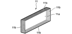
- FIG. 3 is a perspective view of the battery body.
- FIG. 4 is a side view of the lithium ion secondary battery.
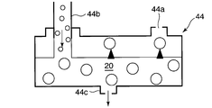
- FIG. 5 is a schematic longitudinal sectional view of an aeration tank provided in the electrolyte solution injection device.
- FIG. 6 is a schematic longitudinal sectional view of a deaeration module provided in the electrolytic solution injector.
- FIG. 7 is a partial longitudinal sectional view of a deaeration pipe for explaining a deaeration process of the deaeration module.
- FIG. 8A-8G are timing charts for explaining the electrolyte injection operation by the electrolyte injection device.
- FIG. 9 is a schematic configuration diagram of an electrolyte injection device showing another embodiment of the present invention.
- the electrolyte solution injection device 1 injects the electrolyte solution 20 into the battery case 12 of the lithium ion secondary battery 10 held by the holding jig 3.
- the electrolyte injection device 1 includes a decompression chamber 2 formed by a sealed container, a decompression line 5 that decompresses the interior of the decompression chamber 2, an air introduction line 6 that restores the interior of the decompression chamber 2 from a decompressed state to atmospheric pressure, And an electrolyte supply line 8 for supplying the liquid 20 to the decompression chamber 2.
- the electrolyte injection device 1 also includes an injection mechanism 4 in the decompression chamber 2 that decompresses the electrolyte 20 supplied from the electrolyte supply line 8 and injects the electrolyte 20 into the battery case 12.
- the electrolyte injection device 1 further includes a controller 7 that controls the decompression line 5, the air introduction line 6, the electrolyte supply line 8, and the liquid injection mechanism 4 outside the decompression chamber 2.
- the lithium ion secondary battery 10 includes a battery main body 11 provided with a positive electrode current collector 103a and a negative electrode current collector 103b, a battery case 12 made of a laminate film that houses the battery main body 11, and a positive electrode.
- a positive electrode tab 104a electrically connected to the current collector 103a and a negative electrode tab 104b electrically connected to the negative electrode current collector 103b are provided.
- the battery body 11 is composed of a cell stack in which a positive electrode plate and a negative electrode plate are stacked via a separator.
- the end surface of the battery body 11 in the cell stacking direction is referred to as a stacking end surface 11a
- the outer peripheral surface of the battery body 11 excluding the stacking end surface 11a is referred to as a stacking side surface 11b.
- the positive electrode plate is made of an aluminum foil formed by applying a positive electrode.
- the negative electrode plate is made of a copper foil formed by coating a negative electrode.
- the positive electrode plate and the negative electrode plate of each cell are connected to a metal film piece 43 that is drawn out from the cell stack region and to which no electrode material is applied.
- the positive electrode current collector 103a is configured by performing ultrasonic welding of the metal film pieces 43 of the positive electrode plates of all cells at once.
- the positive electrode tab 104a is also ultrasonically welded to the positive electrode current collector 103a.
- the negative electrode last powering part 103b is configured by performing ultrasonic welding of the metal film pieces 43 of the negative electrode plates of all cells at once.
- the negative electrode tab 104b is also ultrasonically welded to the negative electrode last charging portion 103b.
- the lithium ion secondary battery 10 discharges from each cell and stores electricity in each cell through the positive electrode tab 104a and the negative electrode tab 104b.
- Battery case 12 is composed of two laminated films.
- the laminate film is composed of a laminate of a heat-fusible resin layer having heat-fusibility, a metal layer, and a protective layer.
- the laminate film is used with the heat-fusible resin layer facing the battery body 11.
- Polypropylene (PP) is used for the heat-fusible resin layer.
- a recess 12e for accommodating the battery body 11 is formed in advance.
- the battery case 12 is configured by bonding two laminate films in a state where the battery main body 11 is housed in the recess 12e, and thermally welding the four sides. However, after the battery body 11 is housed in the recess 12e, first, three sides are thermally welded, and after the electrolyte is injected into the battery case 12 from the opening of the remaining one side, the remaining one side is thermally welded. .
- two flat laminate films may be bonded together so as to wrap the battery body 11, and the battery body 11 may be stored in a space generated by deformation of the laminate film.
- FIG. 4 another configuration of the battery case 12 will be described.
- the battery body 11 is wrapped by folding a single laminate film in half.
- the bottom side 12b of the battery case 12 is a folded side of the laminate film.
- a bag-shaped battery case 12 is formed by providing welded portions 12f on the two left and right sides 12c and 12d of the other three sides that are heat-welded with a laminated film that is in contact therewith.
- the remaining one side 12a of the battery case 12 corresponding to the upper end of the figure is in an open state.
- the injection of the electrolytic solution 20 into the battery case 12 is performed from the opening of the side 12a into the battery case 12. After the injection of the electrolytic solution 20, the side 12a is thermally welded to seal the battery case 12.
- the material of the battery case 12 is not limited to the laminate film.
- the battery case 12 can also be made of metal.
- the electrolytic solution 20 is, for example, propylene mixed in a mass ratio of 50:50 using 1 mol / liter of lithium hexafluorophosphate (LiPF6) or lithium tetrafluoroborate (LiBF4) as a supporting electrolyte. It is comprised with the electrolyte solution which uses carbonate and ethylene carbonate as a mixed solvent.
- LiPF6 lithium hexafluorophosphate
- LiBF4 lithium tetrafluoroborate
- the decompression chamber 2 has a door 21.
- the door 21 carries the battery case 12 containing the battery main body 11 into the decompression chamber 2 together with the holding jig 3, and carries out the battery case 12 that has completed the injection of the electrolyte from the decompression chamber 2 together with the holding jig 3. Is provided.
- the rectangle of the reference numeral 21 shown in the drawing is not a container covering the battery case 12 but a door provided on the wall surface of the decompression chamber 2 behind the battery case 12.
- On the outside of the door 21 a carry-in path and a carry-out path for the battery case 12 are provided.
- the door 21 is opened and closed while the decompression chamber 2 is in an atmospheric pressure state.
- the closed door 21 keeps the inside of the decompression chamber 2 in a sealed state.
- the battery case 12 is carried into the decompression chamber 2, injected into the decompression chamber 2, and unloaded from the decompression chamber 2 while being held by the holding jig 3.
- the holding jig 3 sandwiches two surfaces of the battery case 12 covering the stacked end surface 11a of the battery body 11, and holds the battery case 12 with the opening of the side 12a facing upward.
- the decompression line 5 includes a vacuum pump 5b driven by the electric motor 5c and a valve 5a for connecting the vacuum pump 5b to the decompression chamber 2.
- the decompression line 5 decompresses the interior of the decompression chamber 2 by operating the vacuum pump 5b with the valve 5a opened.
- the atmosphere introduction line 6 includes a decompression chamber 2 and a valve 6a connected to the atmosphere.
- the atmosphere introduction line 6 opens the valve 6a to introduce the atmosphere into the decompressed decompression chamber 2 and raise the internal pressure of the decompression chamber 2 from a vacuum state to an atmospheric pressure state.
- the electrolytic solution supply line 8 includes a storage tank 41 that stores the electrolytic solution 20, a feed pump 43 that pressurizes and supplies the electrolytic solution 20 in the storage tank 41 into the decompression chamber 2, and an electric motor 42 that drives the feed pump 43.
- the liquid injection mechanism 4 provided in the decompression chamber 2 includes an aeration tank 44, a deaeration module 45, and a liquid injection nozzle 46.
- the aeration tank 44 evacuates the electrolytic solution 20 by exposing the electrolytic solution 20 supplied from the feed pump 43 to the decompression chamber 2 to the atmosphere in the decompression chamber 2.
- the aeration tank 44 includes an inflow port 44 b through which the electrolytic solution 20 from the feed pump 43 flows, and an opening 44 a formed at the upper end of the decompression chamber 2.
- the electrolytic solution 20 supplied and pushed from the feed pump 43 is temporarily stored. Thereby, the inside of the aeration tank 44 is separated into a liquid phase below the liquid level of the electrolytic solution 20 and a gas phase above the liquid level.
- An outflow port 44 c communicating with the deaeration module 45 is formed at a position facing the liquid phase of the aeration tank 44.
- the electrolyte 20 flowing into the aeration tank 44 from the inflow port 44b is exposed to the atmosphere in the cochlear tank 2 guided from the opening 44a above the liquid level of the aeration tank 44 through the liquid level in the aeration tank 44. .
- the electrolytic solution 20 reduces the fluid pressure until it becomes equal to the pressure of the atmosphere in the decompression chamber 2.
- the electrolytic solution 20 in the aeration tank 44 is also at atmospheric pressure
- the electrolyte 20 in the aeration tank 44 is also at negative pressure.
- the capacity of the aeration tank 44 is preferably set to such an extent that the amount of electrolyte injected into the battery case 12 can be stored.
- the supply of the electrolytic solution 20 from the feed pump 43 to the aeration tank 44 is performed, for example, every time the battery case 12 is carried into the decompression chamber 2.
- the deaeration module 45 is connected to an outflow port 44 c in the aeration tank 44, and further uses a gas permeable membrane for the electrolyte 20 that has been evacuated and pressure-adjusted in the aeration tank 44. Perform separation.
- the deaeration module 45 includes an inlet chamber 45a communicating with the outflow port 44c of the aeration tank 44, an outlet chamber 45b, and a plurality of deaeration tubes 45c connecting the inlet chamber 45a and the outlet chamber 45b. .
- the deaeration module 45 further includes an airtight chamber 45e that houses a plurality of deaeration tubes 45c, and a check valve 45d that connects the airtight chamber 45e to the atmosphere in the decompression chamber 2.
- the check valve 45d allows air to flow from the airtight chamber 45e to the decompression chamber 2, while preventing air from flowing from the decompression chamber 2 to the airtight chamber 45e.
- the pressure in the airtight chamber 45e is always kept equal to or lower than the pressure in the decompression chamber 2 by the check valve 45d. Further, even when the pressure in the decompression chamber 2 is increased to the atmospheric pressure by the atmospheric introduction line 6, the airtight chamber 45e is kept in a decompressed state.
- the deaeration tube 45c is composed of a resin hollow fiber gas permeable membrane.
- a gas permeable membrane using hollow fibers is non-porous and has a property of transmitting gas molecules having a small size and high mobility.
- the electrolyte solution traveling from the inlet chamber 45a to the outlet chamber 45b through the deaeration pipe 45c disposed in the pressure-tight airtight chamber 45e is always a small dissolved gas having a small size and high mobility.
- the molecules are diffused from the liquid toward the wall of the deaeration tube 45c.
- the diffused gas molecules gather near the inner peripheral surface of the gas permeable membrane according to Fick's law. These gas molecules are taken into the gas permeable membrane in accordance with Henry's law, move through the gas permeable membrane, and are discharged out of the gas permeable membrane.
- the liquid injection nozzle 46 is disposed above the opening of the battery case 12 held at a predetermined position in the decompression chamber 2 by the holding jig 3.
- the liquid injection nozzle 46 is connected to the outlet chamber 45b of the deaeration module 45 through an electromagnetic valve 46a.
- the liquid injection nozzle 46 injects the evacuated electrolytic solution 20 supplied from the deaeration module 45 into the inside of the battery case 12 from the opening according to the excitation of the electromagnetic valve 46a.
- the controller 7 provided outside the decompression chamber 2 is controlled via a signal circuit.
- the controller 7 includes a microcomputer having a central processing unit (CPU), a read only memory (ROM), a random access memory (RAM), and an input / output interface (I / O interface). It is also possible to configure the controller 7 with a plurality of microcomputers.
- FIG. With reference to 8A-8G, the process of injecting the electrolyte 20 into the battery case 12 by the electrolyte injector 1 will be described.
- FIG. 8G the valve 6a of the air introduction line 6 is opened, and the inside of the decompression chamber 2 is released to atmospheric pressure.
- FIG. The door 21 is opened as shown in FIG.
- 8E and 8F the feed pump 43 of the electrolyte supply line 8 and the vacuum pump 5b of the pressure reducing line 5 are stopped.
- liquid injection work to the battery case 12 by the electrolyte injection device 1 is started.
- the controller 7 operates in accordance with the operation of the electric motor 42 of the electrolyte supply line 8 according to FIG. As shown to 8E, the feed pump 43 is operated and the electrolyte solution 20 in the storage tank 41 is supplied to the aeration tank 44.
- FIG. 8A the battery case 12 held by the holding jig 3 is carried into the decompression chamber 2 from the door 21.
- FIG. 8B the door 21 is closed.
- Controller 7 at FIG. 8E supply of the electrolyte solution 20 from the electrolyte solution supply line 8 to the aeration tank 44 is stopped.
- the electrolytic solution 20 supplied to the aeration tank 44 is exposed to the atmosphere of the decompression chamber 2 in the aeration tank 44 from a pressurized state in which the pressurized pressure of the feed pump 43 is added to the atmospheric pressure in the storage tank 41.
- a part of the gas molecules dissolved in the electrolytic solution 20 is reduced to FIG. 5 expands and separates into bubbles.
- FIGS. Referring to 8A-8G at time t5, the controller 7 determines that FIG. As shown in 8G, the valve 6a of the atmosphere introduction line 6 is closed. At the same time, the valve 5a of the decompression line 5 is opened, and the operation of the electric motor 5c is started. As a result, FIG. As shown in 8F, the operation of the vacuum pump 5b is started. Accordingly, FIG. As shown in 8C, the pressure in the decompression chamber 2 is reduced from the atmospheric pressure.
- the controller 7 stops the operation of the electric motor 5c, and FIG. As shown in 8F, the operation of the vacuum pump 5b is stopped. Further, the valve 5a of the decompression line 5 is closed. Thereafter, the decompression chamber 2 is maintained at a vacuum pressure. The inside of the deaeration module 45 and the battery case 12 is also maintained at a vacuum pressure.
- the electrolytic solution 20 is further depressurized by being exposed to a vacuum pressure.
- the density of dissolved gas molecules contained in the electrolytic solution 20 is lowered, and the state is easily moved in the liquid.
- the gas molecules expand in volume to form bubbles, quickly rise in the liquid, reach the liquid surface of the electrolytic solution 20, and are released into the upper space of the aeration tank 44. In this way, the gas-liquid separation of the electrolytic solution 20 in the aeration tank 44 is promoted by the decompression of the decompression chamber 2.
- the controller 7 stops the operation of the vacuum pump 5b at the time t6, and simultaneously opens the electromagnetic valve 46a, and the FIG.
- pouring of the electrolyte solution 20 from the injection nozzle 46 to the battery case 12 is started.
- the injection nozzle 46 starts injecting the electrolyte solution 20
- the electrolyte solution 20 in the aeration tank 44 that sufficiently releases dissolved gas molecules is supplied to the injection nozzle 46 via the deaeration module 45.
- the electrolytic solution 20 further passes through the deaeration module 45 to further separate dissolved gas molecules remaining in the solution. Therefore, the electrolytic solution 20 is supplied to the liquid injection nozzle 46 in a state where gas molecules are almost completely removed.
- the electrolytic solution 20 injected into the battery case 12 is first processed as FIG. 4 flows into the space between the left and right sides 12c and 12d and the battery body 11 from the space above the battery body 11 shown in FIG. 4, and is further filled into the gap between the battery body 11 and the bottom side 12b of the battery case 12. .
- the electrolytic solution 20 injected into the battery case 12 penetrates from the periphery of the battery body 11 into the battery body 11.
- the gas molecules are almost completely removed from the electrolyte solution 20 injected into the battery case 12. Further, the pressure of the electrolytic solution 20 is adjusted in advance in the aeration tank 44 to be equal to the vacuum pressure in the decompression chamber 2.
- the controller 7 synchronizes the injection speed of the injection nozzle 46 with the penetration speed of the electrolyte 20 into the battery body 11. For this reason, when the controller 7 completes a certain amount of liquid injection, the controller 7 closes the electromagnetic valve 46a for a predetermined time, and opens the electromagnetic valve 46a again after the predetermined time has elapsed, thereby performing intermittent liquid injection. As a result, FIG. As shown to 8C, the quantity of the electrolyte solution 20 in the battery case 12 increases in steps. Such control is preferable in preventing injection of the electrolytic solution 20 exceeding the permeation rate into the battery body 11 and preventing the electrolytic solution 20 from overflowing from the battery case 12.
- the amount of the electrolytic solution 20 in the battery case 12 reaches a specified amount.
- the injection of the electrolyte 20 from the injection nozzle 46 at time t6 is started at time t7.
- the period until the injection of the electrolytic solution 20 by the liquid injection nozzle 46 is stopped can be shortened.
- the controller 7 closes the solenoid valve 46a, and the FIG. As shown in 8G, the valve 6a of the atmosphere introduction line 6 is opened, and introduction of the atmosphere into the decompression chamber 2 is started.
- FIG. 8C the pressure in the decompression chamber 2 increases toward the atmospheric pressure. Even if the pressure in the decompression chamber 2 increases, the pressure inside the battery body 11 in the battery case 12 does not increase immediately. This pressure gradient accelerates the penetration of the electrolytic solution 20 into the battery body 11, and the filling operation of the electrolytic solution 20 into the battery body 11 is completed in a short time.
- FIG. 8B When the pressure in the decompression chamber 2 reaches atmospheric pressure at time t8, FIG. As shown in 8B, the door 21 is opened. At time t9, FIG. As shown in 8 ⁇ / b> A, the battery case 12 is carried out of the decompression chamber 2 from the door 21 while being held by the holding jig 3. Thereafter, in the decompression chamber 2, the injection process of the electrolytic solution 20 into another battery case 12 is resumed.
- the battery case 12 carried out from the decompression chamber 2 is sealed by heat-sealing the opening, and the assembly as a lithium ion secondary battery is completed.
- the aeration tank 44 exposes the electrolytic solution 20 to the atmosphere in the decompression chamber 2 to decompress the electrolytic solution 20.
- the density of dissolved gas molecules in the electrolytic solution 20 is lowered, and the state is easily moved in the liquid.
- the gas molecules expand in volume and become bubbles, rapidly rise in the liquid, reach the liquid surface of the electrolytic solution 20, and are extracted into the upper space of the aeration tank 44.
- gas-liquid separation of the electrolytic solution 20 is promoted, and the deaeration efficiency is improved. As a result, the time for pouring into the battery case 12 can be shortened.
- the combination with the deaeration module 45 using a gas permeable membrane makes it possible to completely deaerate the electrolyte solution 20.
- the electrolyte solution 20 when the electrolyte solution 20 is injected from the liquid injection nozzle 46 to the battery case 12, the volume of the gas remaining in the electrolyte solution 20 rapidly expands and the liquid scatters, or the generated bubbles cause the electrolyte solution to be discharged into the battery container. Inconvenience such as overflow from the battery case 12 can be prevented, and the injection efficiency of the electrolyte 20 into the battery case 12 is improved.
- a predetermined amount of the electrolytic solution 20 is stored in advance in the aeration tank 44 in the decompression chamber 2, and the electrolytic solution 20 stored in the aeration tank 44 is exposed to the atmosphere of the decompression chamber 2 during decompression.
- the gas molecules dissolved in the electrolytic solution 20 are separated.
- the supply of the electrolytic solution 20 from the feed pump 43 to the aeration tank 44 can be performed in parallel with the injection of the electrolytic solution 20 into the battery case 12 by the injection nozzle 46.
- the feed pump 43 is operated at time t4 when the door 21 of the decompression chamber 2 is closed or time t5 when decompression is started, and supply of the electrolytic solution 20 from the storage tank 41 to the aeration tank 44 is started.
- the supply of the electrolytic solution 20 from the storage tank 41 to the aeration tank 44 is performed as shown in FIG.
- the flow is continuously performed until the liquid injection by the liquid injection nozzle 46 is completed at a flow rate substantially synchronized with the liquid injection amount of the liquid injection nozzle 46.
- the pressurized electrolyte solution 20 obtained by adding the supply pressure from the feed pump 43 to the atmospheric pressure in the storage tank 41 is decompressed by being exposed to the decompressed atmosphere of the decompression chamber 2 in the aeration tank 44, and accompanying this, the electrolyte solution Dissolved gas molecules in 20 expand and are separated as bubbles. Therefore, regarding the separation of the remaining gas molecules of the electrolytic solution 20, the same preferable effects as in the above-described embodiment can be obtained.
- FIG. 9 another embodiment of the present invention will be described.
- the electrolyte solution injection device 1 includes a pair of aeration tanks 44, a deaeration module 45, and a plurality of liquid injection nozzles 46 connected in parallel to the decompression chamber 2.
- the holding jig 30 holds the same number of battery cases 12 as the liquid injection nozzles 46 in the horizontal direction.
- the plurality of injection nozzles 46 in the decompression chamber 2, it becomes possible to inject the electrolyte 20 into the plurality of battery cases 12 at the same time, and the working efficiency is further improved.
- a plurality of holding jigs 3 similar to those in the first embodiment may be arranged.
- each of the embodiments described above is an embodiment in which the present invention is applied to an electrolytic solution injection device for a lithium ion secondary battery.
- the present invention is applied to an electrolytic solution injection device for an electric two-phase capacitor or electrolytic capacitor. Is also applicable.
- the aeration tank 44 is not necessarily arranged in the decompression chamber 2. It is also possible to arrange the aeration tank 44 outside the decompression chamber 2 by communicating the opening 44 a of the aeration tank 44 with the decompression chamber 2 through a pipe.
- the present invention brings about a favorable effect for improving the working efficiency of injecting the electrolyte into the battery case, and can be applied to the manufacture of various batteries.
Landscapes
- Chemical & Material Sciences (AREA)
- Chemical Kinetics & Catalysis (AREA)
- Electrochemistry (AREA)
- General Chemical & Material Sciences (AREA)
- Engineering & Computer Science (AREA)
- Manufacturing & Machinery (AREA)
- Materials Engineering (AREA)
- Filling, Topping-Up Batteries (AREA)
Abstract
Description
Claims (7)
- 密閉された減圧室と;
減圧室内に配置された電池ケースに電解液を注入する注液ノズルと;
注液ノズルに供給される電解液を減圧室内の圧力に晒す曝気槽と;
を備える電池ケースへの電解液の注入装置。 - 曝気槽と注液ノズルとの間に、気体透過膜を用いて気液を分離する脱気モジュールをさらに備える、請求項1の電解液注入装置。
- 曝気槽は電解液を流入させる流入ポートと、電解液の液面の上方の気相に臨んで形成され、減圧室内の雰囲気に連通する開口部と、電解液の液相に臨んで形成され、脱気モジュールに連通する流出ポートとを備える、請求項2の電解液注入装置。
- 曝気槽を減圧室内に配置するとともに、流入ポートに電解液を供給する減圧室の外側に配置されたフィードポンプをさらに備える、請求項3の電解液注入装置。
- 減圧室は電池ケースの搬入と搬出のための扉を備える、請求項1から4のいずれかの電解液注入装置。
- 複数の注液ノズルを備えた、請求項1から5のいずれかの電解液注入装置。
- 減圧室を密閉し;
電解液を曝気槽の中で減圧室内の圧力に晒し;
減圧室内に配置された電池ケースに曝気槽の電解液を注液ノズルで注入する、
電池ケースへの電解液の注入方法。
Priority Applications (7)
| Application Number | Priority Date | Filing Date | Title |
|---|---|---|---|
| US13/639,719 US9065131B2 (en) | 2010-04-07 | 2011-04-07 | Electrolyte injection device and electrolyte injection method |
| MX2012011544A MX2012011544A (es) | 2010-04-07 | 2011-04-07 | Dispositivo de inyeccion de electrolito y metodo de inyeccion de electrolito. |
| BR112012025762A BR112012025762A2 (pt) | 2010-04-07 | 2011-04-07 | dispositivo de injeção de eletrólito e método de injeção de eletrólito |
| RU2012147274/07A RU2534013C2 (ru) | 2010-04-07 | 2011-04-07 | Устройство впрыска электролита и способ впрыска электролита |
| KR1020127029087A KR101410562B1 (ko) | 2010-04-07 | 2011-04-07 | 전해액 주입 장치 및 전해액 주입 방법 |
| CN201180017444.0A CN102834951B (zh) | 2010-04-07 | 2011-04-07 | 电解液注入装置和电解液注入方法 |
| EP11765968.0A EP2557616B1 (en) | 2010-04-07 | 2011-04-07 | Electrolyte pouring device and electrolyte pouring method |
Applications Claiming Priority (2)
| Application Number | Priority Date | Filing Date | Title |
|---|---|---|---|
| JP2010088696A JP5585174B2 (ja) | 2010-04-07 | 2010-04-07 | 電解液注液方法および電解液注液装置 |
| JP2010-088696 | 2010-04-07 |
Publications (1)
| Publication Number | Publication Date |
|---|---|
| WO2011126068A1 true WO2011126068A1 (ja) | 2011-10-13 |
Family
ID=44763003
Family Applications (1)
| Application Number | Title | Priority Date | Filing Date |
|---|---|---|---|
| PCT/JP2011/058784 Ceased WO2011126068A1 (ja) | 2010-04-07 | 2011-04-07 | 電解液注入装置及び電解液注入方法 |
Country Status (9)
| Country | Link |
|---|---|
| US (1) | US9065131B2 (ja) |
| EP (1) | EP2557616B1 (ja) |
| JP (1) | JP5585174B2 (ja) |
| KR (1) | KR101410562B1 (ja) |
| CN (1) | CN102834951B (ja) |
| BR (1) | BR112012025762A2 (ja) |
| MX (1) | MX2012011544A (ja) |
| RU (1) | RU2534013C2 (ja) |
| WO (1) | WO2011126068A1 (ja) |
Cited By (4)
| Publication number | Priority date | Publication date | Assignee | Title |
|---|---|---|---|---|
| CN102403484A (zh) * | 2011-11-30 | 2012-04-04 | 江苏双登集团有限公司 | 铅酸蓄电池真空注酸方法 |
| CN103545478A (zh) * | 2012-07-16 | 2014-01-29 | 松下能源(无锡)有限公司 | 电解液注液系统及注液方法 |
| WO2015016032A1 (ja) * | 2013-07-31 | 2015-02-05 | Necエナジーデバイス株式会社 | ラミネート型二次電池の製造方法 |
| CN110556505A (zh) * | 2019-08-26 | 2019-12-10 | 龙能科技(宁夏)有限责任公司 | 注液机注液泵的调机装置及方法 |
Families Citing this family (33)
| Publication number | Priority date | Publication date | Assignee | Title |
|---|---|---|---|---|
| US9859569B2 (en) * | 2012-02-07 | 2018-01-02 | Nissan Motor Co., Ltd. | Method and device for manufacturing film-wrapped electrical device |
| JP6213712B2 (ja) * | 2013-04-30 | 2017-10-18 | 日産自動車株式会社 | 注液システム |
| KR102288108B1 (ko) * | 2013-10-05 | 2021-08-09 | 무사시 엔지니어링 가부시키가이샤 | 액체 재료 충전 장치 및 방법 |
| KR101817375B1 (ko) | 2013-11-28 | 2018-01-11 | 주식회사 엘지화학 | 이차 전지용 파우치 및 이를 이용한 이차 전지 |
| RU2582657C1 (ru) * | 2015-03-17 | 2016-04-27 | Открытое акционерное общество "Тюменский аккумуляторный завод" | Способ заполнения герметизированного аккумулятора гелеобразным сернокислым электролитом |
| WO2016167116A1 (ja) * | 2015-04-16 | 2016-10-20 | Necエナジーデバイス株式会社 | 二次電池の製造方法および製造装置 |
| KR102023721B1 (ko) * | 2015-09-04 | 2019-09-20 | 주식회사 엘지화학 | 전해액 함침 장치 및 시스템 |
| CN105702911B (zh) * | 2016-04-22 | 2017-12-19 | 浙江昀邦电池有限公司 | 一种碱性干电池电解液吸收装置 |
| CN105679994B (zh) * | 2016-04-22 | 2017-12-01 | 浙江昀邦电池有限公司 | 一种碱性干电池电解液定量注射机构 |
| CN105702910B (zh) * | 2016-04-22 | 2017-12-19 | 浙江昀邦电池有限公司 | 一种碱性干电池电解液旋转定量注射机构 |
| CN105679996B (zh) * | 2016-04-22 | 2017-12-12 | 浙江昀邦电池有限公司 | 一种电解液负压旋转吸收装置 |
| CN105679993B (zh) * | 2016-04-22 | 2017-12-01 | 浙江昀邦电池有限公司 | 一种碱性干电池电解液注射装置 |
| CN105679995B (zh) * | 2016-04-22 | 2017-12-12 | 浙江昀邦电池有限公司 | 一种电解液负压吸收装置 |
| JP2019145200A (ja) * | 2016-05-31 | 2019-08-29 | 株式会社村田製作所 | 電池およびその製造方法 |
| KR102092269B1 (ko) | 2016-12-01 | 2020-03-23 | 주식회사 엘지화학 | 배터리 셀 디가싱 장치 |
| KR102183772B1 (ko) * | 2016-12-22 | 2020-11-27 | 주식회사 엘지화학 | 전해액 토출 방지용 부재를 사용하는 전지셀 제조방법 |
| KR102264674B1 (ko) * | 2017-01-09 | 2021-06-15 | (주)엘지에너지솔루션 | 진공을 이용한 전해액 주액 방법 |
| KR102264683B1 (ko) * | 2017-01-09 | 2021-06-15 | (주)엘지에너지솔루션 | 진공을 이용한 전해액 주액 방법 |
| JP6977603B2 (ja) * | 2018-02-16 | 2021-12-08 | トヨタ自動車株式会社 | 注液装置 |
| JP7063659B2 (ja) * | 2018-03-06 | 2022-05-09 | 株式会社エンビジョンAescジャパン | 注液装置および注液方法 |
| CN108417771B (zh) * | 2018-05-03 | 2023-09-15 | 大同新成新材料股份有限公司 | 一种锂电池电解液加装装置和加装方法 |
| KR101957503B1 (ko) * | 2018-12-26 | 2019-03-12 | 주식회사 티엠프라자 | 진공호퍼 프리챠져 |
| KR102197731B1 (ko) * | 2019-07-24 | 2021-01-04 | 정종홍 | 이차전지 제조용 디가스 장치 |
| CN112582763B (zh) * | 2019-09-30 | 2023-09-15 | 松下能源(无锡)有限公司 | 真空脱气电解液自动供给装置及使用其供给电解液的方法 |
| JP7410064B2 (ja) * | 2021-02-05 | 2024-01-09 | プライムアースEvエナジー株式会社 | 開放型電池の電解液注液システム及び開放型電池の電解液注液方法 |
| JP2022134410A (ja) * | 2021-03-03 | 2022-09-15 | 株式会社東芝 | 注液装置及び注液方法 |
| CN115842225B (zh) * | 2021-10-19 | 2025-02-18 | 宁德时代新能源科技股份有限公司 | 一种注液装置和注液方法 |
| JP7823506B2 (ja) * | 2022-06-02 | 2026-03-04 | 株式会社豊田自動織機 | 産業車両のバッテリ補水用補助具 |
| EP4331736A4 (en) * | 2022-07-19 | 2024-10-30 | Zhuhai Titans New Power Electronics Co., Ltd | CLEANING METHOD AND CLEANING TOOL FOR NEGATIVE PRESSURE ASSEMBLY FOR BATTERY FORMING |
| CN115395189B (zh) * | 2022-09-30 | 2024-06-28 | 星恒电源股份有限公司 | 注液孔负压密封方法 |
| EP4425694B1 (de) * | 2023-03-03 | 2025-06-11 | VAF Gesellschaft für Verkettungsanlagen, Automationseinrichtungen und Fördertechnik mbH | Befüllvorrichtung zum befüllen einer batteriezelle mit einem elektrolyt sowie verfahren zum betreiben einer befüllvorrichtung |
| CN117049640A (zh) * | 2023-09-11 | 2023-11-14 | 深圳信息职业技术学院 | 一种含油废水破乳除油的方法 |
| KR20250110576A (ko) * | 2024-01-12 | 2025-07-21 | 주식회사 엘지에너지솔루션 | 전해액 주입 및 함침 장치와 그 방법 |
Citations (7)
| Publication number | Priority date | Publication date | Assignee | Title |
|---|---|---|---|---|
| JPH09102443A (ja) | 1995-10-05 | 1997-04-15 | Awa Eng Co | 電解液の充填方法 |
| JP2000340215A (ja) * | 1999-05-26 | 2000-12-08 | Sony Corp | 電池製造における電解液注入方法及び電解液注入装置 |
| JP2001317682A (ja) * | 2000-05-02 | 2001-11-16 | Toshiba Battery Co Ltd | 配管用継手およびそれを用いた注液装置 |
| JP2003151532A (ja) * | 2001-11-15 | 2003-05-23 | Awa Eng Co | 電池またはコンデンサーの外装缶に充填液を注液する注液装置 |
| JP2004327161A (ja) * | 2003-04-23 | 2004-11-18 | Matsushita Electric Ind Co Ltd | 密閉型電池の電解液注液方法および電解液注液装置 |
| JP2007173063A (ja) * | 2005-12-22 | 2007-07-05 | Matsushita Electric Ind Co Ltd | 扁平形電池の製造方法およびその製造装置 |
| JP2010008869A (ja) | 2008-06-30 | 2010-01-14 | Fujitsu Ltd | マッハツェンダ型光変調器 |
Family Cites Families (10)
| Publication number | Priority date | Publication date | Assignee | Title |
|---|---|---|---|---|
| JPH02148572A (ja) * | 1988-11-29 | 1990-06-07 | Japan Storage Battery Co Ltd | 密閉鉛蓄電池の電解液注入法 |
| DE4325464A1 (de) * | 1993-07-29 | 1995-02-02 | Emmerich Christoph Gmbh Co Kg | Akkumulator mit Kunststoffgehäuse |
| US5487417A (en) * | 1993-09-03 | 1996-01-30 | Toshiba Battery Co., Ltd. | Electrolyte injection apparatus |
| RU2157022C1 (ru) * | 1999-08-10 | 2000-09-27 | Инженерная фирма "Орион-ХИТ" | Устройство для нейтрализации паров электролита в литий-тионилхлоридной батарее |
| JP2001110400A (ja) * | 1999-10-04 | 2001-04-20 | Nec Mobile Energy Kk | 電解液注入装置および電解液注入方法 |
| DE10029532C2 (de) * | 2000-06-15 | 2002-10-17 | Christoph Thielen | Befülleinrichtung umfassend einen Füllstopfen, sowie dessen Verwendung |
| US6465121B1 (en) * | 2000-08-30 | 2002-10-15 | Lev M. Dawson | Method for distributing electrolyte in batteries |
| US20050244705A1 (en) * | 2004-04-28 | 2005-11-03 | Jing-Yih Cherng | Electrolyte injection and degas method of electric energy storage device |
| RU2338285C1 (ru) * | 2007-03-01 | 2008-11-10 | Закрытое Акционерное Общество Научно-Производственное Предприятие "Инкар-М" | Способ заливки электролитом конденсатора и устройство для его реализации |
| CN201243051Y (zh) | 2008-08-20 | 2009-05-20 | 苏州星恒电源有限公司 | 一种锂电池电解液的注液装置 |
-
2010
- 2010-04-07 JP JP2010088696A patent/JP5585174B2/ja active Active
-
2011
- 2011-04-07 CN CN201180017444.0A patent/CN102834951B/zh active Active
- 2011-04-07 US US13/639,719 patent/US9065131B2/en active Active
- 2011-04-07 WO PCT/JP2011/058784 patent/WO2011126068A1/ja not_active Ceased
- 2011-04-07 KR KR1020127029087A patent/KR101410562B1/ko active Active
- 2011-04-07 EP EP11765968.0A patent/EP2557616B1/en active Active
- 2011-04-07 RU RU2012147274/07A patent/RU2534013C2/ru not_active IP Right Cessation
- 2011-04-07 MX MX2012011544A patent/MX2012011544A/es active IP Right Grant
- 2011-04-07 BR BR112012025762A patent/BR112012025762A2/pt not_active IP Right Cessation
Patent Citations (7)
| Publication number | Priority date | Publication date | Assignee | Title |
|---|---|---|---|---|
| JPH09102443A (ja) | 1995-10-05 | 1997-04-15 | Awa Eng Co | 電解液の充填方法 |
| JP2000340215A (ja) * | 1999-05-26 | 2000-12-08 | Sony Corp | 電池製造における電解液注入方法及び電解液注入装置 |
| JP2001317682A (ja) * | 2000-05-02 | 2001-11-16 | Toshiba Battery Co Ltd | 配管用継手およびそれを用いた注液装置 |
| JP2003151532A (ja) * | 2001-11-15 | 2003-05-23 | Awa Eng Co | 電池またはコンデンサーの外装缶に充填液を注液する注液装置 |
| JP2004327161A (ja) * | 2003-04-23 | 2004-11-18 | Matsushita Electric Ind Co Ltd | 密閉型電池の電解液注液方法および電解液注液装置 |
| JP2007173063A (ja) * | 2005-12-22 | 2007-07-05 | Matsushita Electric Ind Co Ltd | 扁平形電池の製造方法およびその製造装置 |
| JP2010008869A (ja) | 2008-06-30 | 2010-01-14 | Fujitsu Ltd | マッハツェンダ型光変調器 |
Non-Patent Citations (1)
| Title |
|---|
| See also references of EP2557616A4 |
Cited By (6)
| Publication number | Priority date | Publication date | Assignee | Title |
|---|---|---|---|---|
| CN102403484A (zh) * | 2011-11-30 | 2012-04-04 | 江苏双登集团有限公司 | 铅酸蓄电池真空注酸方法 |
| CN103545478A (zh) * | 2012-07-16 | 2014-01-29 | 松下能源(无锡)有限公司 | 电解液注液系统及注液方法 |
| WO2015016032A1 (ja) * | 2013-07-31 | 2015-02-05 | Necエナジーデバイス株式会社 | ラミネート型二次電池の製造方法 |
| JPWO2015016032A1 (ja) * | 2013-07-31 | 2017-03-02 | Necエナジーデバイス株式会社 | ラミネート型二次電池の製造方法 |
| CN110556505A (zh) * | 2019-08-26 | 2019-12-10 | 龙能科技(宁夏)有限责任公司 | 注液机注液泵的调机装置及方法 |
| CN110556505B (zh) * | 2019-08-26 | 2024-02-09 | 龙能科技(宁夏)有限责任公司 | 注液机注液泵的调机装置及方法 |
Also Published As
| Publication number | Publication date |
|---|---|
| MX2012011544A (es) | 2012-11-16 |
| US20130029186A1 (en) | 2013-01-31 |
| JP2011222221A (ja) | 2011-11-04 |
| CN102834951B (zh) | 2015-07-08 |
| KR20130006683A (ko) | 2013-01-17 |
| EP2557616A1 (en) | 2013-02-13 |
| RU2534013C2 (ru) | 2014-11-27 |
| US9065131B2 (en) | 2015-06-23 |
| RU2012147274A (ru) | 2014-05-20 |
| BR112012025762A2 (pt) | 2016-06-28 |
| CN102834951A (zh) | 2012-12-19 |
| EP2557616B1 (en) | 2014-04-02 |
| EP2557616A4 (en) | 2013-11-13 |
| JP5585174B2 (ja) | 2014-09-10 |
| KR101410562B1 (ko) | 2014-06-23 |
Similar Documents
| Publication | Publication Date | Title |
|---|---|---|
| CN102834951B (zh) | 电解液注入装置和电解液注入方法 | |
| JP5786043B2 (ja) | フィルム外装電気デバイスの製造方法及び製造装置 | |
| KR101256343B1 (ko) | 필름 외장 전기 디바이스의 제조 방법 및 제조 장치 | |
| KR101705503B1 (ko) | 전지의 제조 방법 및 제조 장치 | |
| JP6163740B2 (ja) | フィルム外装電気デバイスの製造方法及び製造装置 | |
| JP2014502410A (ja) | 電気化学セルを充填するための方法および装置 | |
| CN103137997B (zh) | 薄膜封装电气器件的制造方法和制造装置 | |
| CN109417156A (zh) | 使用间隙控制夹具将电解质注入袋型二次电池的方法 | |
| KR20190060214A (ko) | 전해질 주입장치 및 전해액 주입방법 | |
| JP2001273884A (ja) | 密閉形電池およびその製造方法 | |
| CN103137940B (zh) | 薄膜封装电气器件的制造方法和制造装置 | |
| JP2000182599A (ja) | 電解液の注液装置およびその方法 | |
| JP2013105564A (ja) | 電気デバイスの製造方法及びその製造装置並びに電気デバイス | |
| KR101739853B1 (ko) | 전해액 함침 장치 및 이를 이용하는 이차 전지의 제조 방법 | |
| WO2016021066A1 (ja) | 電池の製造装置 | |
| JP2013109855A (ja) | 電気デバイスの製造方法、製造装置及び電気デバイス | |
| JP2003059485A (ja) | 電解液注入方法及び装置 | |
| JP4876957B2 (ja) | 液体燃料の充填装置及び液体燃料の充填方法 | |
| JP2009135374A (ja) | 電気二重層キャパシタの製造方法およびその製造装置。 | |
| JP2001110692A (ja) | 電気二重層コンデンサ用電極積層体、並びに該電気二重層コンデンサ用電極積層体の不純物除去装置及び電解液含浸装置 | |
| WO2023119401A1 (ja) | 二次電池の製造方法 | |
| CN116111202A (zh) | 一种锂离子电池的封装工艺 | |
| JP2020035663A (ja) | 蓄電モジュールの製造方法及び電解液注入装置 |
Legal Events
| Date | Code | Title | Description |
|---|---|---|---|
| WWE | Wipo information: entry into national phase |
Ref document number: 201180017444.0 Country of ref document: CN |
|
| 121 | Ep: the epo has been informed by wipo that ep was designated in this application |
Ref document number: 11765968 Country of ref document: EP Kind code of ref document: A1 |
|
| DPE1 | Request for preliminary examination filed after expiration of 19th month from priority date (pct application filed from 20040101) | ||
| WWE | Wipo information: entry into national phase |
Ref document number: MX/A/2012/011544 Country of ref document: MX |
|
| WWE | Wipo information: entry into national phase |
Ref document number: 13639719 Country of ref document: US |
|
| NENP | Non-entry into the national phase |
Ref country code: DE |
|
| ENP | Entry into the national phase |
Ref document number: 20127029087 Country of ref document: KR Kind code of ref document: A |
|
| WWE | Wipo information: entry into national phase |
Ref document number: 3394/KOLNP/2012 Country of ref document: IN |
|
| ENP | Entry into the national phase |
Ref document number: 2012147274 Country of ref document: RU Kind code of ref document: A |
|
| WWE | Wipo information: entry into national phase |
Ref document number: 2011765968 Country of ref document: EP |
|
| REG | Reference to national code |
Ref country code: BR Ref legal event code: B01A Ref document number: 112012025762 Country of ref document: BR |
|
| ENP | Entry into the national phase |
Ref document number: 112012025762 Country of ref document: BR Kind code of ref document: A2 Effective date: 20121008 |