WO2011126330A2 - Procédé destiné à transmettre des informations et émetteur - Google Patents
Procédé destiné à transmettre des informations et émetteur Download PDFInfo
- Publication number
- WO2011126330A2 WO2011126330A2 PCT/KR2011/002463 KR2011002463W WO2011126330A2 WO 2011126330 A2 WO2011126330 A2 WO 2011126330A2 KR 2011002463 W KR2011002463 W KR 2011002463W WO 2011126330 A2 WO2011126330 A2 WO 2011126330A2
- Authority
- WO
- WIPO (PCT)
- Prior art keywords
- generation matrix
- codeword
- generated
- matrix
- bit
- Prior art date
- Legal status (The legal status is an assumption and is not a legal conclusion. Google has not performed a legal analysis and makes no representation as to the accuracy of the status listed.)
- Ceased
Links
Images
Classifications
-
- H—ELECTRICITY
- H04—ELECTRIC COMMUNICATION TECHNIQUE
- H04B—TRANSMISSION
- H04B7/00—Radio transmission systems, i.e. using radiation field
- H04B7/02—Diversity systems; Multi-antenna system, i.e. transmission or reception using multiple antennas
- H04B7/04—Diversity systems; Multi-antenna system, i.e. transmission or reception using multiple antennas using two or more spaced independent antennas
- H04B7/06—Diversity systems; Multi-antenna system, i.e. transmission or reception using multiple antennas using two or more spaced independent antennas at the transmitting station
- H04B7/0613—Diversity systems; Multi-antenna system, i.e. transmission or reception using multiple antennas using two or more spaced independent antennas at the transmitting station using simultaneous transmission
- H04B7/0615—Diversity systems; Multi-antenna system, i.e. transmission or reception using multiple antennas using two or more spaced independent antennas at the transmitting station using simultaneous transmission of weighted versions of same signal
- H04B7/0617—Diversity systems; Multi-antenna system, i.e. transmission or reception using multiple antennas using two or more spaced independent antennas at the transmitting station using simultaneous transmission of weighted versions of same signal for beam forming
-
- H—ELECTRICITY
- H03—ELECTRONIC CIRCUITRY
- H03M—CODING; DECODING; CODE CONVERSION IN GENERAL
- H03M13/00—Coding, decoding or code conversion, for error detection or error correction; Coding theory basic assumptions; Coding bounds; Error probability evaluation methods; Channel models; Simulation or testing of codes
- H03M13/61—Aspects and characteristics of methods and arrangements for error correction or error detection, not provided for otherwise
- H03M13/615—Use of computational or mathematical techniques
- H03M13/616—Matrix operations, especially for generator matrices or check matrices, e.g. column or row permutations
-
- H—ELECTRICITY
- H03—ELECTRONIC CIRCUITRY
- H03M—CODING; DECODING; CODE CONVERSION IN GENERAL
- H03M13/00—Coding, decoding or code conversion, for error detection or error correction; Coding theory basic assumptions; Coding bounds; Error probability evaluation methods; Channel models; Simulation or testing of codes
- H03M13/63—Joint error correction and other techniques
- H03M13/635—Error control coding in combination with rate matching
- H03M13/6356—Error control coding in combination with rate matching by repetition or insertion of dummy data, i.e. rate reduction
-
- H—ELECTRICITY
- H03—ELECTRONIC CIRCUITRY
- H03M—CODING; DECODING; CODE CONVERSION IN GENERAL
- H03M13/00—Coding, decoding or code conversion, for error detection or error correction; Coding theory basic assumptions; Coding bounds; Error probability evaluation methods; Channel models; Simulation or testing of codes
- H03M13/63—Joint error correction and other techniques
- H03M13/635—Error control coding in combination with rate matching
- H03M13/6362—Error control coding in combination with rate matching by puncturing
-
- H—ELECTRICITY
- H03—ELECTRONIC CIRCUITRY
- H03M—CODING; DECODING; CODE CONVERSION IN GENERAL
- H03M13/00—Coding, decoding or code conversion, for error detection or error correction; Coding theory basic assumptions; Coding bounds; Error probability evaluation methods; Channel models; Simulation or testing of codes
- H03M13/65—Purpose and implementation aspects
- H03M13/6522—Intended application, e.g. transmission or communication standard
- H03M13/6525—3GPP LTE including E-UTRA
-
- H—ELECTRICITY
- H03—ELECTRONIC CIRCUITRY
- H03M—CODING; DECODING; CODE CONVERSION IN GENERAL
- H03M13/00—Coding, decoding or code conversion, for error detection or error correction; Coding theory basic assumptions; Coding bounds; Error probability evaluation methods; Channel models; Simulation or testing of codes
- H03M13/03—Error detection or forward error correction by redundancy in data representation, i.e. code words containing more digits than the source words
- H03M13/05—Error detection or forward error correction by redundancy in data representation, i.e. code words containing more digits than the source words using block codes, i.e. a predetermined number of check bits joined to a predetermined number of information bits
- H03M13/13—Linear codes
- H03M13/136—Reed-Muller [RM] codes
-
- H—ELECTRICITY
- H03—ELECTRONIC CIRCUITRY
- H03M—CODING; DECODING; CODE CONVERSION IN GENERAL
- H03M13/00—Coding, decoding or code conversion, for error detection or error correction; Coding theory basic assumptions; Coding bounds; Error probability evaluation methods; Channel models; Simulation or testing of codes
- H03M13/03—Error detection or forward error correction by redundancy in data representation, i.e. code words containing more digits than the source words
- H03M13/05—Error detection or forward error correction by redundancy in data representation, i.e. code words containing more digits than the source words using block codes, i.e. a predetermined number of check bits joined to a predetermined number of information bits
- H03M13/13—Linear codes
- H03M13/15—Cyclic codes, i.e. cyclic shifts of codewords produce other codewords, e.g. codes defined by a generator polynomial, Bose-Chaudhuri-Hocquenghem [BCH] codes
- H03M13/151—Cyclic codes, i.e. cyclic shifts of codewords produce other codewords, e.g. codes defined by a generator polynomial, Bose-Chaudhuri-Hocquenghem [BCH] codes using error location or error correction polynomials
- H03M13/152—Bose-Chaudhuri-Hocquenghem [BCH] codes
-
- H—ELECTRICITY
- H03—ELECTRONIC CIRCUITRY
- H03M—CODING; DECODING; CODE CONVERSION IN GENERAL
- H03M13/00—Coding, decoding or code conversion, for error detection or error correction; Coding theory basic assumptions; Coding bounds; Error probability evaluation methods; Channel models; Simulation or testing of codes
- H03M13/03—Error detection or forward error correction by redundancy in data representation, i.e. code words containing more digits than the source words
- H03M13/23—Error detection or forward error correction by redundancy in data representation, i.e. code words containing more digits than the source words using convolutional codes, e.g. unit memory codes
Definitions
- the present invention relates to encoding of information bits in a wireless communication system, and more particularly, to a method of generating codewords based on block encoding.
- IMT-Advanced aims to support IP (Internet Protocol) -based multimedia services at data rates of 1 Gbps in stationary and slow motions and 500 Mbps in high speeds.
- IP Internet Protocol
- 3rd Generation Partnership Project is a system standard that meets the requirements of IMT-Advanced.
- Long Term Evolution is based on Orthogonal Frequency Division Multiple Access (OFDMA) / Single Carrier-Frequency Division Multiple Access (SC-FDMA) transmission.
- OFDMA Orthogonal Frequency Division Multiple Access
- SC-FDMA Single Carrier-Frequency Division Multiple Access
- LTE-Advanced LTE-Advanced
- LTE-A is being prepared.
- LTE-Advanced is one of the potential candidates for IMT-Advanced.
- the next generation wireless communication system requires a high speed communication system capable of processing and transmitting various information such as video and wireless data.
- One of the most fundamental problems in achieving high speed communication is how efficiently and reliably data can be transmitted through a channel. Is it? Unlike the wired channel environment, the wireless channel environment inherent in the wireless communication system is inevitable due to various factors such as multipath interference, shadowing, propagation attenuation, time-varying noise, interference, and fading. Errors occur and loss of information.
- Channel coding is a process of generating codewords by encoding information bits to prevent loss of such information.
- a codeword refers to a bit string made by performing specific processing on information bits in order to improve detection performance when transmitting information bits.
- Channel coding includes block coding (block coding) and trellis (channel coding).
- Block coding includes channel coding using BCH (Bose-Chadhuri-Hocquenghem) code or Reed-Muller (RM) code. Codewords in block coding may be generated using a matrix block called a generating matrix. Unlike channel coding in trellis type, block coding has no relationship between the front and rear blocks because there is no memory between successive blocks. For trellis channel coding, using convolution code or turbo code
- Codewords in trellis-type channel coding can be made using polynomials such as generating polynomials.
- a TFCI (Transmit Format Combination Indicator) code is used as a channel code for encoding channel information of an uplink control channel.
- the TFCI code is designed by puncturing the lead-muller code. Since the TFCI code can be regarded as a modified lead-muller code, the TFCI code is similar to the lead-muller code. can do.
- the TFCI code supports various information bit and codeword bit sizes, which is suitable for the requirements of channel information encoding.
- a decoder of 3GPP standard can be used, it can be used in hardware of a dual mode system of wide band code division multiple access (WCDMA) and LTE.
- WCDMA wide band code division multiple access
- a generation matrix of (20,10) codes and a generation matrix of (18,10) codes generated by puncturing a (32,10) TFCI code generation matrix are used.
- the first digit in parentheses is an index indicating the length of the codeword
- the second digit is an information bit size.
- a channel code having an information bit of 24 has been required, and a generation matrix supporting this is required.
- An object of the present invention is to generate codewords when extended information bits are input.
- it is necessary to generate a generation matrix by performing puncturing with a smaller amount of computation.
- an information transmission method includes receiving an information bit;
- the size of a row is the same as the length of the information bits, the size of a column is 24 columns, and the information bits are encoded by using a first generation matrix in which a symbol value, which is an element of a matrix, is filled with 0 or 1.
- Generating a codeword of 48 bits in length And modulating and transmitting the generated codeword.
- the first generation matrix is generated by puncturing eight columns in the first generation matrix having a column size of 32 columns.
- the first generation matrix is generated by using the first generation matrix. It can be generated by using the codeword twice.
- the 48-bit codeword may be generated by repeating a 24-bit codeword generated twice using the first generation matrix.
- Generating the 48-bit codeword may further include: changing the order of the bits in the 24-bit codeword generated using the first generation matrix.
- the 48-bit codeword may be generated by combining a 24-bit codeword generated by using the first generation matrix, and a 24-bit codeword having the same bit value as that of the 24-bit codeword but having a changed order of the bit values. have.
- the 48-bit codeword is generated by repeating a codeword in which the order of bits is changed twice from a 24-bit codeword generated by using the first generation matrix, or by changing two 24-bit codes respectively. Can be generated by combining the codewords of the bits.
- Generating the 48-bit codeword may further include: changing the order of the bits such that zero symbols are not contiguous.
- the first generation matrix comprises: dividing the columns of the original generation matrix into a plurality of sections; It can be generated by drilling any heat in each section.
- an embodiment of the present invention provides an information transmission method.
- the information transmission method includes receiving an information bit;
- the size of a row is the same as the length of the information bits, the size of a column is 48 columns, and the information bits are encoded by using a first generation matrix in which a symbol value, which is an element of a matrix, is filled with 0 or 1.
- the first generation matrix may be generated based on a second generation matrix having a row size equal to the length of the information bit and having a column size of 24 columns.
- the second generation matrix may be generated by puncturing eight columns in the first generation matrix having a column size of 32 columns.
- the first generation matrix may be generated by repeating the second generation matrix.
- the first generation matrix may be generated by combining the second generation matrix and a modified generation matrix based on the second generation matrix.
- the modified generation matrix may be generated by exchanging an order of any columns in the second generation matrix.
- the first generation matrix may be generated by combining two modified generation matrices based on the second generation matrix.
- an embodiment of the present invention provides a transmitter.
- the transmitter inputs information by using a first generation matrix having a row size equal to the length of the information bit, a column size 24 columns, and a value of a symbol, which is an element of a matrix, filled with 0 or 1
- the first generation matrix is generated by puncturing eight columns in the first generation matrix having a column size of 32 columns.
- the first generation matrix is generated by using the first generation matrix. It may be generated by using the codeword twice.
- an embodiment of the present invention also provides a transmitter.
- the transmitter receives information using a first generation matrix in which a row size is equal to the length of the information bit, a column size is 48 columns, and a value of a symbol, which is an element of a matrix, is filled with 0 or 1
- An encoder for encoding a bit to generate a 48-bit codeword It may include a modulator for modulating the generated codeword.
- the first generation matrix may be generated based on a second generation matrix having a row size equal to the length of the information bit and having a column size of 24 columns.
- LTE-A Long Term Evolution-Advanced
- a generation matrix for generating codewords with a smaller amount of computation.
- the length of codeword ego For an information bit size of 1 to y + 1 of the in-read muller code, a generation matrix can be created without complex operations to generate a set of read-muller codewords having an optimal Hamming weight distribution.
- performance may be improved by maximizing diversity through column substitution of a generator matrix for eliminating zero (symbol) symbols.
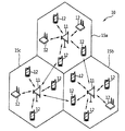
- 1 shows a wireless communication system.
- FIG. 2 shows a structure for transmitting information using channel coding in a 3GPP (LTE / LTE-A) uplink control channel system.
- 3GPP LTE / LTE-A
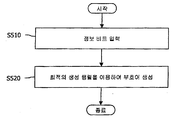
- FIG. 3 is a flowchart illustrating a method of generating a codeword according to the present invention.
- FIG. 5 is a flowchart illustrating a codeword generation method according to the present invention.
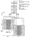
- FIG. 6 illustrates generating an optimal generation matrix according to an example.
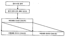
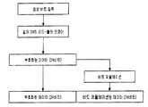
- FIG. 8 is an exemplary diagram illustrating a method of generating a codeword having a length of 48 according to an example of the present invention.
- FIG. 9 is a diagram illustrating an example of generating a codeword having a length of 48 bits in accordance with the illustrated method.
- 10 is a diagram illustrating another example of generating a codeword having a length of 48 bits according to the illustrated method.
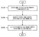
- FIG. 11 is an exemplary diagram illustrating a process of generating a generation matrix having 48 columns by using a generation matrix having 24 columns in length according to an example of the present invention.
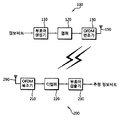
- FIG. 12 is a block diagram illustrating a transmitter and a receiver according to an embodiment of the present invention.
- the wireless communication system can provide various communication services such as voice, packet data, and the like.
- the wireless communication system 10 includes at least one base station (BS) 11.
- the base station 11 generally refers to a fixed station communicating with the terminal 12, and may be referred to as other terms such as an evolved-NodeB (eNB), a base transceiver system (BTS), an access point, and the like. have.
- eNB evolved-NodeB
- BTS base transceiver system
- access point and the like. have.
- Each base station 11 provides a communication service for a particular geographic area (generally called a cell) 15a, 15b, 15c.
- the cell can in turn be divided into a number of regions (called sectors).
- the UE 12 may be fixed or mobile, and may include a mobile station (MS), a mobile terminal (MT), a user terminal (UT), a subscriber station (SS), a wireless device, and a PDA. (Personal Digital Assistant), a wireless modem (wireless modem), a handheld device (handheld device) may be called other terms.
- Downlink means communication from a base station (BS) to a user equipment (UE), and uplink means communication from a terminal to a base station.
- BS base station
- UE user equipment
- uplink means communication from a terminal to a base station.
- the transmitter may be part of the base station, and the receiver may be part of the terminal.
- a transmitter is part of a terminal and a receiver may be part of a base station.
- a process of generating a codeword based on the read-muller code will be described.
- a communication system based on a lead-muller code is widely used. It demonstrates using.
- the present invention is not limited to the lead-muller code.
- the generation matrix G is the basis sequence (or vector) v1, v2, v3, v4 as shown in Equation 1 below. It can be expressed as, v5,1. Alternatively, Equation 1 may be represented by 1, v5, v4, v3, v2, and v1 in reverse order.
- the generator matrix refers to a matrix on which the codeword is generated.
- the information bit m can be expressed as in Equation 2 below. Assuming that the size of G is 6x36, the length of the input information bit is six.
- the codeword b which is a modulo operation result of the product of the information bit and the generation matrix G, may be expressed as in Equation 3 below.
- the receiver may determine what information bits are transmitted by receiving and decoding a specific transmission sequence called a codeword generated in this way. In an unreserved channel whose error probabilities from one symbol to the next are independent of each other, the receiver compares the received sequence with all possible codewords, taking into account the reliability of the received symbol and taking into account the nearest sign of the received sequence. Choose a language.
- the number of different information bits between the received sequence and the codeword or the number of different information bits between the codewords is called a hamming distance, and the smallest distance among all codewords in the codeword set is coded.
- An important factor in determining the performance of a circuit is called the minimum distance. For example, suppose you have the code words 000, 010, and 110. The distance between 000 and 110 is 2, the distance between 000 and 010 is 1, and the distance between 010 and 110 is 1, so the minimum distance is 1.
- the minimum distance of a block code is d min , the codewords of the block code have different values at least d min at each other.
- the minimum distance can be increased as the number of bits (parity bits) added in the encoding process increases, excellent detection performance can be obtained.
- transmission efficiency can be lowered.
- the probability of misrecognition of the received signal as another code word increases, which decreases the detection performance and is sensitive to the error difference due to channel compensation. Because performance is determined, performance degradation can occur in rapidly changing channels.
- the detection performance and the transmission efficiency are in a trade-off relationship with each other.
- the (32, O) Reed-Muller (RM) generation matrix may use the matrix provided by the 3GPP specification (see 5.2.2.6.4 of 3GPP TS36.212 V8.6.0).
- a (20, O) RM generation matrix that punctures the (32, O) RM generation matrix to generate Channel Quality Indication (CQI) information of a Physical Uplink Control Channel (PUCCH).
- the (18, O) RM generation matrix may be used.
- the (32, O) RM generation matrix and the (32,10) RM generation matrix are used interchangeably.
- the (32, O) RM generation matrix ego In the case of (32, 10), since the RM generation matrix can be used while removing the last row, even if the two terms are used in the same meaning, there is no problem in the contents of the present invention.
- the (20,10) RM generation matrix and the (18,10) RM generation matrix may be generated by puncturing the (32,10) RM generation matrix.
- puncturing the (18,10) RM generation matrix may be generated by puncturing two additional rows in the (20,10) RM generation matrix, wherein the (20,10) RM generation matrix is completely separate from the (20,10) RM generation matrix. It does not have a structure.
- the (18,10) RM generation matrix may be generated from the (32,10) RM generation matrix.
- perforation results can be obtained as shown in Table 1 below.
- M i and n represent symbols constituting the generation matrix of the TFCI code in the nth column.
- i represents an information bit.
- the codeword can be obtained by using the remainder (modulo operation) divided by 2 after the information bits are internalized in each row of the generation matrix.
- Table 2 below shows the minimum distance performance of the generated matrix.
- n the number of bits after performing channel coding
- k the number of information bits
- FIG. 2 shows a structure for transmitting information using channel coding in a 3GPP (LTE / LTE-A) uplink control channel system.
- 3GPP LTE / LTE-A
- an encoded bit is generated through channel coding.
- a punctured lead-muller code, a tail biting convolutional code (TBCC) or a turbo code may be used.
- the coded bit may be rate-match with the available subcarriers.
- the coded bits are modulated such as binary phase-shift keying (BPSK), quadrature phase-shift keying (QPSK), 8 phase-shift keying (8PSK), 16 quadrature amplitude modulation (16QAM), or 64 quadrature amplitude modulatino (64QAM).
- BPSK binary phase-shift keying
- QPSK quadrature phase-shift keying
- 8PSK 8 phase-shift keying
- 16QAM 16 quadrature amplitude modulation
- 64QAM 64 quadrature amplitude modulatino
- Each slot uses 12 subcarriers to transmit information. Two slots may be used at the same time in one subframe, and 24 subcarriers are used when two slots are used at the same time. Therefore, when using BPSK modulation, a coded bit requires 24 bits, and when using QPSK modulation, a coded bit requires 48 bits. That is, a sign of at least 24 bits long is required.
- consecutive zeros in the generation matrix may cause a problem that channel information is not contained in a symbol transmitted during QPSK transmission.
- Table 3 shows an example of a (20,10) RM generation matrix.
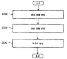
- FIG. 3 is a flowchart illustrating a method of generating a codeword according to the present invention.
- a generation matrix is generated based on the length of the information bits to be input (S310).
- the size of the columns of the generation matrix is equal to the length of the information bits and the size of the rows is 24 rows.
- the generated generation matrix is row-substituted so that consecutive zeros are positioned in the generation matrix to prevent zero symbols from being generated and change the transmission information to have diversity (S320). Generating the generation matrix and changing the generation matrix by row substitution will be described later.
- a codeword is generated from the remaining information obtained by dividing the input information bit and each generated column of the generated matrix by dividing by two (S330).
- b i is a codeword
- O is the length of the information bit
- o n is the input information bit
- M i , n represent the nth column of the generation matrix
- i represents 24 rows of the generation matrix.
- All. B is 24, the size of the row.
- the generation matrix used to generate the codeword is a (24, A) RM generation matrix in which four rows are added to the existing (20,10) RM generation matrix and columns are selected by the length A of the information bits.
- the length A of the information bits may be one to six.
- Four new rows are added to the (20,10) RM generation matrix from the (24, A) of 12 rows perforated to form the (20,10) RM generation matrix from the existing (32,10) RM generation matrix.
- Four rows are selected that provide the best minimum distance performance of the RM generation matrix.
- the size of the information bit is changed from 10 to A. Since A is a number less than or equal to 6, a maximum of 6 columns are selected from the existing 10 columns. At this time, it is known that the performance of the primary read-muller code is better than that of the secondary read-muller code due to the characteristics of the read-muller code. Since the TFCI code is generated from the read-muller code, You can select six columns to create a generation matrix. This corresponds to supporting the information bit length of 1 to 6 of the (32,10) TFCI code currently used, so that the (24, A) generation matrix using 1 to 6 columns of the (32,10) generation matrix Creating an TFCI decoder has the effect of using the existing TFCI decoder.
- the extended generation matrix according to the present invention is formed by using columns 1 to 6 of the generation matrix currently used in the LTE-Advanced (LTE-A) standard (Chapter 5.2.2.6.4 of 3GPP TS36.212 V8.6.0). Can be generated.
- LTE-A LTE-Advanced
- TS36.212 V8.6.0 3GPP TS36.212 V8.6.0
- rows 0 through 19 of the (20,10) RM generation matrix may be used as is, and four new rows may be added to generate a new generation matrix.
- the additional row is selected from the set of additional rows that makes the minimum distance performance and distance distribution of the codeword generated for an information bit length of 1 to 6 optimal, which can be obtained through computer simulation.
- Tables 4 to 9 show examples of a row set having a minimum distance performance and an optimal distance distribution by computer simulation.
- Table 4 compares an example of the newly generated (24,6) RM generation matrix with the (20,10) RM generation matrix and the (18,10) RM generation matrix.
- the (24,6) RM generation matrix further includes the 14th, 20th, 21st and 24th rows of the (32,10) RM generation matrix compared to the (20,10) RM generation matrix.
- Table 5 shows the generated (24,6) RM generation matrices.
- Table 6 shows another example of comparing the newly generated (24,6) RM generation matrix with the (20,10) RM generation matrix and the (18,10) RM generation matrix.
- the newly generated (24,6) RM generation matrix further includes 14th, 20th, 24th, and 29th rows of the (32,10) RM generation matrix compared to the (20,10) RM generation matrix.
- Table 7 shows the generated (24,6) RM generation matrices.
- Table 8 compares another example of the newly generated (24,6) RM generation matrix with the (20,10) RM generation matrix and the (18,10) RM generation matrix.
- the newly generated (24,6) RM generation matrix further includes the 14th, 24th, 28th and 29th rows of the (32,10) RM generation matrix compared to the (20,10) RM generation matrix.
- Table 9 shows the generated (24,6) RM generation matrices.
- the (24, A) RM code was generated by puncturing eight rows in the (32,10) RM code generation matrix. It can be generated by adding four rows from the existing (20, A) RM code generation matrix, and four rows punctured in the (20, A) RM code but not perforated in the (24, A) RM code. You can create a new generation matrix by adding
- a new generation matrix of (24, A) RM codes can be generated by adding six rows in the generation matrix of (18, A) RM codes.
- the set of rows added to the generation matrix of the (20, A) RM code is ⁇ 1, 14, 20,29 ⁇ , ⁇ 1,14,21,28 ⁇ , ⁇ 1,14,28,29 ⁇ , ⁇ 1,21,28,29 ⁇ and ⁇ 20,21,24,29 ⁇ .
- newly added rows may be inserted in an interleaved form into an existing table. It can also be added to the end of the generation matrix for implementations that are legacy compatible.
- Changing the generation matrix by performing such a row replacement first, divides all rows of the generation matrix of the (24,10) RM code into upper and lower n groups (where n may be 12). Let n be the same number of 1s in each n rows.
- each slot may be mapped in an interleaved format. That is, odd-numbered symbols are mapped to the first slot and even-numbered symbols are mapped to the second slot, or conversely, even-numbered symbols are mapped to the first slot and odd-numbered symbols are mapped to the second slot.
- the codeword is generated using the generation matrix of the code (24, A).
- symbols for all subcarriers of all slots may be allocated in the LTE-Advanced ACK / NACK feedback.
- the decoder can be reused in the system when supporting WCDMA and LTE dual mode, thereby reducing the hardware.
- performance through diversity may be improved through row reordering of generation matrices for eliminating zero symbols.
- the Hamming distance is a number in which the values of corresponding bits do not coincide between binary codes having the same number of bits.
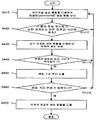
- a punctured generation matrix is created using the original generation matrix (S410). If the hamming weight of each row is between the upper and lower boundary values (S420), a code set is generated using the punctured generation matrix (S430). If not, go back to the first step and create the perforated generation matrix again.
- the first step is to create a perforated generation matrix.
- this generation matrix is an optimized perforated generation matrix (S470). If not, the first step is to create the perforated generation matrix again.
- the number of puncturing cases should be more efficient.
- the scope of the present invention is not limited thereto.
- x rows are punctured in a generation matrix of a primary read-muller code having a parameter of (2 n , A), where x rows are punctured between codewords of (a, A) code.
- Minimal distance performance is best.
- a of the information bit becomes smaller than n + 1, A of n + 1 columns is selected. If A is 1, the matrix A ⁇ 1 with all elements 1 is the generation matrix, and for A, the other column is selected to give the best performance between minimum codewords.
- a differential vector between codewords becomes another codeword.
- the codeword set must include an all-zero vector of all values that are codewords for the case where all information bits are zero. Therefore, the minimum distance between the codewords in the code set and the minimum value of the Hamming weight of the codewords in the codeset are the same. Hamming weight is the number of non-symbols in a string. Also, because there is an all one column in the generation matrix, there is always an all zero vector and an all one vector. Are all codewords, and the following equation (6) holds for any two codewords in the code set.
- the maximum value of the minimum distance between codewords of the read-muller code having the coded bit size of 2e is e.
- the matrix G is made up of one all-one vector and one primary vector y as rows.
- the primary vector is a vector having the same number of 1 symbols and 0 symbols.
- Equation 7 the generation matrix G is expressed by Equation 7 below.
- the matrix G has one all-one vector and three primary vectors.
- G' denotes all binary y-tuple vectors. Each row has 2 ny times.
- the y-tuple vector refers to a vector having y symbols.
- Equation 8 G 'is a form having a 3-tuple vector 2 4 times, and G' is represented by Equation 8 below.
- the row of the matrix G ', there 24-3 each have 23 kinds of the binary 3-tuple vectors.
- the Hamming weight is 2 n-1 codewords having 0 and 1 2 n-1 times, respectively.
- the characteristic of the lead-muller code as shown in the above-described generation matrix of the lead-muller code is that (2 n , y + 1) all y-tuple vectors are repeated the same number of times in the column of G 'which is a sub-matrix of the generation matrix G.
- a codeword set with a Hamming weight of 2 n-1 comes out. That is, it is possible to know whether or not a set having the maximum minimum distance performance between codewords of the read-muller code can be obtained from the generation matrix.
- FIG. 5 is a flowchart illustrating a codeword generation method according to the present invention.
- an information bit is input (S510).
- a codeword is generated using an optimal generation matrix having a column size equal to the length of the information bit (S520). Details of the optimal generation matrix will be described later.
- the optimal generation matrix having the same size as the length of the information bits may be generated by puncturing the generation matrix of the read-muller code.
- the optimal generation matrix is generated by puncturing the (2 n , y + 1) generation matrix, which is the original generation matrix G.
- x is the number of rows to be drilled and b is obtained from x and y.
- the optimal algorithm is searched for puncturing and the corresponding puncturing is performed to generate the optimal generation matrix.
- the (2 n , y + 1) matrix G is formed by arranging one all-one vector and one primary vector y as rows.
- the column of the original generation matrix G is divided into 2y.
- 2 y is called a partition coefficient.
- FIG. 6 illustrates generating an optimal generation matrix according to an example.
- the generation matrix G may be divided into 2 2 , that is, quadranted by Equation 9 below.
- the rows of each section are all the same symbol (all one symbol or all). All zero symbols).
- all codewords generated for codewords having 1 to y + 1 information bits have only three cases of 0, a / 2, and a (0, 10, 20 in the above case).
- the hamming distance distribution between the stems is also optimal.
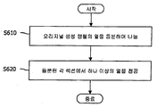
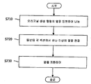
- the columns of the original generation matrix are divided into equal parts (S710). Then, one or more rows are punctured in each of the divided sections (S720).
- the generation matrix is changed by applying column substitution to the perforated matrix.
- linear operation may be applied to eliminate zero symbols as much as possible, thereby preventing performance degradation and efficiently obtaining diversity performance.
- the method of performing the thermal substitution is similar to the method of performing the row substitution described above. That is, when the concept of row substitution is transformed into column substitution and applied to the generation matrix, first, the rows of the second generation and the fourth set are exchanged by dividing the rows of the entire generation matrix by four. This makes the number of 1s distributed in the left and right halves of the generation matrix the same.
- thermal substitution is performed so that zeros do not appear consecutively in each sub-matrix having three sets of left and right halves.
- generating a codeword using a perforated generation matrix has the following advantages.
- performance improvement through diversity can be obtained through column permutation of the generation matrix to eliminate zero symbols.
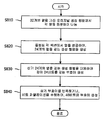
- FIG. 8 is an exemplary diagram illustrating a method of generating a codeword having a length of 48 according to an example of the present invention.
- FIG. 9 is a diagram illustrating an example of generating a codeword having a length of 48 bits in accordance with the illustrated method.
- 10 is a diagram illustrating another example of generating a codeword having a length of 48 bits according to the illustrated method.
- 8 columns of 32 columns of the generation matrix G are punctured to generate a generation matrix having 24 columns.
- the number of columns is equally divided and divided (S810), and a predetermined number of columns are punctured in each divided session to generate a generation matrix having 24 columns ( S820).
- a codeword having a length of 24 bits is generated using the generation matrix having 24 columns (S830).
- the codeword is simply repeated or bit permutation is performed on the repeated bits, thereby generating a 48-bit codeword (S840).
- the input information bits are encoded into 24 bits by using an encoder using a generation matrix having 24 columns generated by the aforementioned S830 process.
- the coded 24-bit data is repeated to generate a 48-bit codeword.
- the input information bits are encoded into 24 bits by using an encoder using a generation matrix having 24 columns generated by S830.
- bit permutation is performed on the encoded 24-bit codeword.
- the coded 24-bit codeword and the bit-substituted codeword are combined to generate a 48-bit codeword.
- the encoded 24-bit codeword may be stored in a register.
- bit-substituted 24-bit codeword may be located before or after 48-bit codeword.
- a 48-bit codeword may be generated by combining two bit-permutated 24-bit codewords.
- bit substitution performed on the first 24 bits is the same as the bit substitution performed on the subsequent 24 bits. It can be different.
- the 24-bit codeword is simply repeated or bit permutation is performed on the repeated bits to generate 48-bit codeword.
- a generation matrix having 24 columns is different.
- a 48-bit codeword may be generated using a generation matrix having 48 columns generated by iteratively.
- FIG. 11 is an exemplary diagram illustrating a process of generating a generation matrix having 48 columns by using a generation matrix having 24 columns in length according to an example of the present invention.
- each column is divided into equal parts in the original generation matrix having 32 columns (S1110), and a predetermined number of columns are punctured in each divided session to generate a generation matrix having 24 columns (S1120). Subsequently, a generation matrix having 48 columns is generated using the generation matrix having 24 columns (S1130).
- Equation 14 For example, a generation matrix that generates a 24-bit codeword A generation matrix that produces a 48-bit codeword. In this case, the relationship expressed in Equation 14 below may be established.
- the generation matrix of Table 1 may be repeated to generate a generation matrix having 48 columns.
- G24 may be a matrix as shown in Equation 17 below.
- the generation matrix G 24 having 24 columns may be combined with the generation matrix G 24 having 24 columns replaced with each other to generate the generation matrix G 48 having 48 columns.
- G24 may be a matrix as shown in Equation 19 below.
- G '24 can be represented as shown in Equation 20 below.
- P1 is a substitution matrix for replacing the matrix G 24 .
- Equation 21 This may be expressed as Equation 21 below.
- G ′ 24 may be expressed as follows.
- P 1 is a substitution matrix for replacing the matrix G 24 .
- the G ′′ 24 may be as follows.
- P 1 and P 2 are substitution matrices for replacing the matrix G 24 .
- G 24 may be a matrix represented by Equation 23 below.
- the rows of the entire generator matrix are divided into quarters to exchange positions of the set of second rows and the set of fourth rows with each other.
- the number of 1s distributed in the upper half and the lower half of the generation matrix is equal.
- adjust the position or order of the rows so that zero does not appear twice in succession within each sub-matrix with up and down half rows.
- the row position or order is adjusted so that consecutive zeros belong to different symbols in transmission. That is, if 00 occurs, the position of 00 is adjusted so that the first 0 and the second 0 belong to different modulated symbols. That is, row substitution is performed so that the start of zero is in the odd-numbered row.
- FIG. 12 is a block diagram illustrating a transmitter and a receiver according to an embodiment of the present invention.
- the transmitter 100 may include a codeword generator 110, a mapper 120, and an OFDM modulator 130.
- the codeword generator 110 generates a codeword by the codeword generation method according to the present invention described with reference to FIGS. 2 to 11.
- the mapper 120 modulates the codeword according to a predetermined modulation scheme and maps the codewords to symbols representing positions according to amplitude and phase constellation.
- the OFDM modulator 130 converts the input symbols into OFDM symbols.
- the OFDM modulator 130 may perform Inverse Fast Fourier Transform (IFFT) on the input symbols and convert them into time domain samples.
- IFFT Inverse Fast Fourier Transform
- CP cyclic prefix
- the OFDM symbol output from the OFDM modulator 130 is transmitted through the transmit antenna 190.
- the receiver 200 includes an OFDM demodulator 210, a demapper 220, and a codeword detector 230.
- the signal received from the receive antenna 290 is converted by the OFDM demodulator 210 into symbols in the frequency domain.
- the OFDM demodulator 210 may remove a CP from an input signal and perform a fast fourier transform (FFT).
- Demapper 220 demaps input symbols.
- the codeword detector 230 detects the estimated information bits through auto-correlation and cross-correlation of the codeword.
- the transmitter 100 and the receiver 200 show a single-input single-output (SISO) scheme having one transmit antenna and one receive antenna
- SISO single-input single-output
- MIMO multiple-input multiple-output
- the transmitter 100 and the receiver 200 show an orthogonal frequency division multiplexing (OFDM) / orthogonal frequency division multiple access (OFDMA) based system
- OFDM orthogonal frequency division multiplexing
- OFDMA orthogonal frequency division multiple access
- the technical concept of the present invention is TDMA (Time Division Multiple Access) and CDMA (Code). Division Multiple Access) can be applied to other wireless access-based systems.
Landscapes
- Engineering & Computer Science (AREA)
- Physics & Mathematics (AREA)
- Probability & Statistics with Applications (AREA)
- Theoretical Computer Science (AREA)
- Computational Mathematics (AREA)
- General Physics & Mathematics (AREA)
- Mathematical Analysis (AREA)
- Mathematical Optimization (AREA)
- Mathematical Physics (AREA)
- Pure & Applied Mathematics (AREA)
- Algebra (AREA)
- Computing Systems (AREA)
- Computer Networks & Wireless Communication (AREA)
- Signal Processing (AREA)
- Dc Digital Transmission (AREA)
- Error Detection And Correction (AREA)
Abstract
Selon un mode de réalisation de la présente invention, un procédé destiné à transmettre des informations est décrit. Le procédé destiné à transmettre des informations comprend : une étape consistant à acquérir, en tant qu'entrée, des bits d'informations ; une étape consistant à coder les bits d'informations de façon à générer un mot de code qui présente une longueur de 48 bits, à l'aide d'une première matrice de génération dans laquelle la taille d'une colonne est identique à la longueur des bits d'informations, le nombre de rangées étant égal à 24 et la valeur du symbole qui est un élément de la matrice étant égal à 0 ou à 1 ; et une étape consistant à moduler le mot de code ainsi généré et à transmettre le mot de code modulé. La première matrice de génération est générée en exécutant des perforations dans 8 rangées dans la matrice de génération originale qui présente 32 rangées. L'étape consistant à générer un mot de code qui présente une longueur de 48 bits implique une étape consistant à générer le mot de code à l'aide d'un mot de code qui présente 24 bits généré par la première matrice de génération deux fois.
Applications Claiming Priority (2)
| Application Number | Priority Date | Filing Date | Title |
|---|---|---|---|
| US32182710P | 2010-04-07 | 2010-04-07 | |
| US61/321,827 | 2010-04-07 |
Publications (2)
| Publication Number | Publication Date |
|---|---|
| WO2011126330A2 true WO2011126330A2 (fr) | 2011-10-13 |
| WO2011126330A3 WO2011126330A3 (fr) | 2012-03-15 |
Family
ID=44763427
Family Applications (1)
| Application Number | Title | Priority Date | Filing Date |
|---|---|---|---|
| PCT/KR2011/002463 Ceased WO2011126330A2 (fr) | 2010-04-07 | 2011-04-07 | Procédé destiné à transmettre des informations et émetteur |
Country Status (1)
| Country | Link |
|---|---|
| WO (1) | WO2011126330A2 (fr) |
Cited By (1)
| Publication number | Priority date | Publication date | Assignee | Title |
|---|---|---|---|---|
| CN118868961A (zh) * | 2024-07-12 | 2024-10-29 | 安徽大学 | 一种基于rm码递归列表译码的打孔方法及系统 |
Family Cites Families (4)
| Publication number | Priority date | Publication date | Assignee | Title |
|---|---|---|---|---|
| RU2234187C2 (ru) * | 2000-10-06 | 2004-08-10 | Самсунг Электроникс Ко., Лтд. | Способ и устройство для формирования (n, 3) кода и (n, 4)кода с использованием симплексных кодов |
| KR100879942B1 (ko) * | 2002-02-16 | 2009-01-22 | 엘지전자 주식회사 | 채널품질지시자 코딩을 위한 기저수열 생성방법 |
| KR100970645B1 (ko) * | 2007-12-24 | 2010-07-15 | 엘지전자 주식회사 | 블록 코드를 이용한 다양한 길이를 가진 정보의 채널 코딩방법 |
| KR100983282B1 (ko) * | 2007-12-24 | 2010-09-24 | 엘지전자 주식회사 | 블록 코드를 이용한 다양한 길이를 가진 정보의 채널 코딩방법 |
-
2011
- 2011-04-07 WO PCT/KR2011/002463 patent/WO2011126330A2/fr not_active Ceased
Cited By (1)
| Publication number | Priority date | Publication date | Assignee | Title |
|---|---|---|---|---|
| CN118868961A (zh) * | 2024-07-12 | 2024-10-29 | 安徽大学 | 一种基于rm码递归列表译码的打孔方法及系统 |
Also Published As
| Publication number | Publication date |
|---|---|
| WO2011126330A3 (fr) | 2012-03-15 |
Similar Documents
| Publication | Publication Date | Title |
|---|---|---|
| WO2022197087A1 (fr) | Procédé et appareil pour transmettre un canal de liaison montante dans un système de communication sans fil | |
| WO2019194635A1 (fr) | Appareil et procédé de codage et de décodage au moyen d'un code polaire dans un système de communication sans fil et dans un système de diffusion | |
| WO2017018839A1 (fr) | Procédé et appareil pour rapport de csi | |
| WO2018212558A1 (fr) | Procédé et appareil de codage/décodage dans un système de communication ou de diffusion utilisant une modulation d'ordre élevé | |
| WO2019190281A1 (fr) | Appareil et procédé de codage et de décodage à l'aide d'un code polaire dans un système de communication sans fil | |
| WO2018101799A1 (fr) | Procédé et appareil pour des transmissions multiflux | |
| WO2010018980A2 (fr) | Procédé et appareil pour la transmission d’un signal de commande dans un système de radiocommunication | |
| WO2016108658A1 (fr) | Procédé destiné à transmettre un accusé de réception/accusé de réception négatif dans un système de communication sans fil et dispositif l'utilisant | |
| WO2011105813A2 (fr) | Procédé et dispositif destinés à fournir des informations de commande pour une transmission en liaison montante dans un système de communication sans fil supportant une transmission en liaison montante à antennes multiples | |
| WO2013172674A1 (fr) | Procédé et dispositif de communication d'informations d'état de canal | |
| WO2022186678A1 (fr) | Appareil et procédé de transmission et de réception de données et de signaux de commande dans un système de communication | |
| WO2018124779A1 (fr) | Procédé et appareil destinés à effectuer une harq sur la base d'un code polaire | |
| WO2022240162A1 (fr) | Procédé et appareil de transmission d'un canal de liaison montante dans un système de communication sans fil | |
| WO2017196117A2 (fr) | Schéma de communication utilisant un schéma de forçage d'entier dans un système de communication sans fil | |
| WO2010056069A2 (fr) | Procédé et appareil pour la transmission de données au moyen d'une pluralité de ressources dans un système à antennes multiples | |
| WO2011043598A2 (fr) | Procédé et appareil de transmission en liaison montante dans un système multi-antenne | |
| WO2018182369A1 (fr) | Procédé pour effectuer un codage sur la base d'une matrice de contrôle de parité de code de contrôle de parité à faible densité (ldpc) dans un système de communication sans fil et terminal l'utilisant | |
| WO2013125908A1 (fr) | Procédé et appareil de transmission d'informations de commande | |
| WO2022211596A1 (fr) | Procédés réalisés par un équipement d'utilisateur ou une station de base, équipement d'utilisateur et station de base | |
| WO2019031841A1 (fr) | Procédé de transmission d'informations et dispositif de transmission, et procédé de réception d'informations et dispositif de réception | |
| WO2013105836A1 (fr) | Procédé et appareil pour transmettre des informations de commande en liaison montante | |
| WO2020067637A1 (fr) | Dispositif et procédé de codage et de décodage à l'aide d'un code polaire dans un système de communication sans fil | |
| WO2013137682A1 (fr) | Procédé et appareil pour émettre des informations de commande de liaison montante | |
| WO2018151555A1 (fr) | Procédé de transmission d'informations, et dispositif de transmission | |
| WO2009136751A2 (fr) | Procédé et appareil de génération de mots de code dans un système de communication sans fil |
Legal Events
| Date | Code | Title | Description |
|---|---|---|---|
| 121 | Ep: the epo has been informed by wipo that ep was designated in this application |
Ref document number: 11766181 Country of ref document: EP Kind code of ref document: A2 |
|
| NENP | Non-entry into the national phase |
Ref country code: DE |
|
| 122 | Ep: pct application non-entry in european phase |
Ref document number: 11766181 Country of ref document: EP Kind code of ref document: A2 |