WO2011126334A2 - 휴대용 표시장치 - Google Patents
휴대용 표시장치 Download PDFInfo
- Publication number
- WO2011126334A2 WO2011126334A2 PCT/KR2011/002470 KR2011002470W WO2011126334A2 WO 2011126334 A2 WO2011126334 A2 WO 2011126334A2 KR 2011002470 W KR2011002470 W KR 2011002470W WO 2011126334 A2 WO2011126334 A2 WO 2011126334A2
- Authority
- WO
- WIPO (PCT)
- Prior art keywords
- panel housing
- plate
- display
- housing
- spring
- Prior art date
- Legal status (The legal status is an assumption and is not a legal conclusion. Google has not performed a legal analysis and makes no representation as to the accuracy of the status listed.)
- Ceased
Links
Images




Classifications
-
- G—PHYSICS
- G06—COMPUTING OR CALCULATING; COUNTING
- G06F—ELECTRIC DIGITAL DATA PROCESSING
- G06F1/00—Details not covered by groups G06F3/00 - G06F13/00 and G06F21/00
- G06F1/16—Constructional details or arrangements
- G06F1/1613—Constructional details or arrangements for portable computers
- G06F1/1615—Constructional details or arrangements for portable computers with several enclosures having relative motions, each enclosure supporting at least one I/O or computing function
- G06F1/1624—Constructional details or arrangements for portable computers with several enclosures having relative motions, each enclosure supporting at least one I/O or computing function with sliding enclosures, e.g. sliding keyboard or display
-
- G—PHYSICS
- G06—COMPUTING OR CALCULATING; COUNTING
- G06F—ELECTRIC DIGITAL DATA PROCESSING
- G06F1/00—Details not covered by groups G06F3/00 - G06F13/00 and G06F21/00
- G06F1/16—Constructional details or arrangements
- G06F1/1613—Constructional details or arrangements for portable computers
- G06F1/1633—Constructional details or arrangements of portable computers not specific to the type of enclosures covered by groups G06F1/1615 - G06F1/1626
- G06F1/1637—Details related to the display arrangement, including those related to the mounting of the display in the housing
-
- G—PHYSICS
- G06—COMPUTING OR CALCULATING; COUNTING
- G06F—ELECTRIC DIGITAL DATA PROCESSING
- G06F1/00—Details not covered by groups G06F3/00 - G06F13/00 and G06F21/00
- G06F1/16—Constructional details or arrangements
- G06F1/1613—Constructional details or arrangements for portable computers
- G06F1/1633—Constructional details or arrangements of portable computers not specific to the type of enclosures covered by groups G06F1/1615 - G06F1/1626
- G06F1/1637—Details related to the display arrangement, including those related to the mounting of the display in the housing
- G06F1/1647—Details related to the display arrangement, including those related to the mounting of the display in the housing including at least an additional display
-
- G—PHYSICS
- G06—COMPUTING OR CALCULATING; COUNTING
- G06F—ELECTRIC DIGITAL DATA PROCESSING
- G06F1/00—Details not covered by groups G06F3/00 - G06F13/00 and G06F21/00
- G06F1/16—Constructional details or arrangements
- G06F1/1613—Constructional details or arrangements for portable computers
- G06F1/1633—Constructional details or arrangements of portable computers not specific to the type of enclosures covered by groups G06F1/1615 - G06F1/1626
- G06F1/1662—Details related to the integrated keyboard
-
- G—PHYSICS
- G09—EDUCATION; CRYPTOGRAPHY; DISPLAY; ADVERTISING; SEALS
- G09F—DISPLAYING; ADVERTISING; SIGNS; LABELS OR NAME-PLATES; SEALS
- G09F9/00—Indicating arrangements for variable information in which the information is built-up on a support by selection or combination of individual elements
Definitions
- the present invention relates to a method of using two displays as a single screen, and more particularly, to at least two panel housings equipped with a display in a stacked state, and when the panel housing is moved by sliding the display.
- the present invention relates to providing a structure in which the interconnections are connected to each other within 0.1 mm to 5 mm so that they can be used as a single display.
- a flat panel display panel used may include LCD, OLED, FED, PDP, and electric paper.
- a separate panel housing that is slidable is provided, and when the display is mounted on each of the panel housings, the displays are configured to be adjacent to each other.
- the seam is a non-screen display area generated between the display.
- the seams are minimized by arranging the displays effectively designed on one side to be adjacent to each other.
- the present invention is characterized in that when the panel housing in the stacked state up and down is unfolded, the two displays can be connected to each other to form a single screen, so that the displays in the stacked state are positioned at the same height. It is an object to provide a moving means in the vertical direction together with the sliding means in the left and right directions.
- At least two panel housings are stacked on top and bottom, respectively, and a display is mounted on the upper and lower panel housings, and the upper and lower panel housings are slidably moved in the left and right directions, respectively, and also in the vertical direction.
- the distance between the displays is within 0.1 mm to 5 mm, and is separated between the upper panel housing and the lower panel housing.
- the separate moving means is characterized in that to move the left and right direction and the vertical direction while supporting the upper panel housing.
- the width of the moving means is characterized in that it is wider than the width of the protective cover or cover support, and furthermore, the panel housings may be in close contact with each other, when not apart, characterized in that not more than 1.5mm.
- the moving means is further provided with an elastic member to control the movement of the moving means, an input device is provided on the top of the display.
- FIG. 4 is a view showing a state in which the upper panel housing is removed.
- Figure 5 is a view from below of the upper panel housing.
- 6 to 9 are views showing a state in which the lower cover is removed.
- 17 is a view showing the operating principle of the projection board.
- FIG. 18 is a view of another embodiment in which the protrusion plate is slid.
- 19 is a view showing the principle of movement by the moving bar.
- 20 to 22 are views illustrating the movement of the panel housing.
- 27 to 29 are diagrams showing the movement of the projection board.
- FIG. 30 is a view showing a panel housing having a protective cover removed.
- 31 is an enlarged view of a seam of a display.
- 32 is an enlarged view of an input device and is an enlarged view of a portion B of FIG. 5.
- 33 illustrates a case in which an input device is mounted on the top of the display.
- 35 to 37 are diagrams of embodiments in which the shape of the protective cover is changed.
- 38 and 39 are views illustrating the lower panel housing.
- 40 is a diagram of another embodiment using a spring assembly.
- FIG. 41 is a structural diagram showing a sliding principle of FIG.
- FIG. 42 is a view showing a plate and a support plate.
- FIG. 43 is a view illustrating the sliding principle of FIG. 42.
- 44 is a view showing a side plate provided on the base plate.
- 45 is a view showing the engaging projection of the lower panel housing.
- 46 is a principle diagram in which the panel housing moves by the projection head.
- 47 to 49 are views illustrating a principle in which the upper panel housing and the lower panel housing move in the left and right directions and in the up and down directions.
- 50 is a view showing a cross-sectional shape of the bottom plate.
- 51 and 52 are views showing the principle of the path that the panel housing moves through the spring projection.
- 53 is a view illustrating movement of the upper and lower panel housings.
- 54-57 show an embodiment of a spring assembly.
- 58 to 65 are diagrams of yet another embodiment of the sliding structure.
- 65 and 66 are views of the embodiment provided with the extension.
- 67 is a view showing an example of the coupling means.
- 68 and 69 are views of another embodiment in which the lower panel housing is moved.
- 70 to 73 show examples of design variations.
- 74 to 76 are views of an embodiment in which the lower panel housing is moved.
- 77 is a sectional view of the panel housings 20 and 40 with different thicknesses.
- 79-81 are illustrations of embodiments with frame housings.
- 83 to 86 illustrate a method of mounting a display.
- 87 is a view showing the size of the fixing plate or plate.
- 88 is a diagram showing an embodiment when using as a mobile phone.
- 89 is a diagram of the embodiment when used for character input or the like.
- 90 is a circuit block diagram of a portable display device.
- 91 and 92 are flowcharts illustrating input keyboard modes according to sensors.
- 96 and 97 are diagrams of yet another exemplary embodiment in which a key input unit is provided.
- the present invention provides a folding portable display device having an effect of viewing at least one screen by interconnecting at least two flat panel displays.
- a flat panel display panel LCD, OLED, FED, PDP, Electric Paper, etc. may be used, and in addition, all flat panel displays may be used.
- the two displays are connected to each other within 0.1mm or more and less than 5mm to form a single screen.
- the lower panel housing 40 equipped with the lower display 4 is provided below the upper panel housing 20 on which the upper display 2 is mounted, and the upper and lower panel housings 20 and 40 overlap each other and are stacked. In this case, the seam 8 of the upper display 2 is protected by the lid 43.
- the lower cover 43a is configured to move in the vertical direction from the side of the lower panel housing 40. That is, when the lower cover 43 slides downward, the upper panel housing 20 on the lower cover 43 also moves downward.
- the lower cover 43 is provided on the side of the lower panel housing 40 to protect the joint portion 8 of the lower display 4.
- the lower display 4 does not protect the seam, and as a result, the upper and lower displays 2 and 4 are adjacent to each other.
- FIG. 4 is a view showing a state in which the upper panel housing is removed.
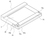
- a projection plate 71 is provided on the upper end of the lower cover 43a as a sliding means.
- the protruding plate 71 supports the upper panel housing 20 to allow the upper panel housing 20 to be slidably moved, and the protruding groove 72 serves as a sliding movement.
- the projection plate 71 and the fixing portion 75 which is a sliding means is made of a metal alloy or the like to be durable. Then, the sliding movement to the projection groove 72 of the projection plate 71 is possible.
- the projection board is fixed to the lower cover (43a) by screws or other fixing method.
- Figure 5 is a view from below of the upper panel housing.
- a leg 20b is provided below the upper panel housing 20 so as to be formed higher than the bottom surface of the upper panel housing.
- a bottom groove 80 is formed at the bottom of the upper panel housing 20, and the protrusion 72 of the protrusion plate 71 is engaged with the bottom groove 80 so as to slide.
- the bottom groove 80 is made by the bottom plate (81). That is, there are protrusions at both edges of the bottom plate 81 to engage with the protrusion groove 72.
- 6 to 9 are views showing a state in which the lower cover is removed.
- the vertical movement means provided in the joint portion of the lower panel housing 40 appears.
- the vertical movement means allows the lower cover 43a to slide in the upper and lower directions in the lower panel housing 40.
- the vertical movement means is composed of a support plate 90, the spring device 91 is further provided on both sides of the support plate 90. Inner grooves 90a are provided at both sides of the support plate 90, and an inner bottom 92 is also provided.
- FIG 8 is a view showing that the elastic support plate 91a in the form of a leaf spring is provided in the inner groove 90a on both sides of the support plate 90.
- FIG 9 is a view in which the inner bottom 92 provided below the support plate 90 is partially movable in the downward direction.
- the bottom support plate 93 is further provided below the inner bottom 92, and the bottom support plate 93 is movable to the bottom groove 93a and the spring 93b.
- the lower cover 43a is coupled with the panel housing seam side.
- Internal spaces 94 are formed on both side surfaces of the lower cover 43a, and coupling portions 95 are provided in the internal spaces 94.
- the coupling portion 95 is formed of a head 95a and an attachment portion 95b, and the coupling portion 95 is fixed to the internal space 94 through the attachment portion 95b.
- the coupling portion 95 is engaged with the inner groove (90a) on both sides of the support plate 90 to move.
- the movement of the coupling portion 95 is limited by the inner bottom 92. In other words, the lower lid 43a is prevented from falling downward more than necessary.
- the engaging projection 95c is to be combined with the elastic support plate 91a of the previous figure.
- FIG. 13 is a diagram illustrating a vertical error of the upper and lower panel housings.
- ß should not exceed about 1,5 mm or 2.0mm.
- the reason is for two displays 2 and 4 to meet the purpose of the present invention to form one screen.
- the lower panel housing 40 is an embodiment provided with a moving means for supporting and moving the upper panel housing 20.
- the projection means 76 is provided as the moving means.
- the protrusion is made of steel, stainless steel or alloy as a metal material to increase the robustness.
- an upper panel housing 20 is mounted on the top of the protrusion plate 76, and the upper panel housing 20 is supported by two or more fixing protrusions 76a.
- the projection plate 76 may be in a state of Figure 15 by sliding more outward. That is, when the width (width) of the lower cover (43a) is narrowed to have a wider effect to securely support the upper panel housing 20.
- a fixing protrusion 76b is further provided below the protrusion plate as shown in FIG. 16.
- the lower cover 43a allows the protrusion plate 76 to support and move through the fixing protrusion 76b.
- 17 is a view showing the operating principle of the projection board.
- a square groove 77 is provided at the top of the lower cover 43a, and the leaf spring 77a is provided in the square groove as shown in the drawing.
- the fixing protrusion 76b is coupled between the leaf springs 77a to slide.
- FIG. 18 is a view of another embodiment in which the protrusion plate is slid.
- a moving bar 78 and a moving shaft 78a are provided below the protrusion plate 76. Therefore, the protrusion plate 76 is moved from the upper portion of the lower cover 43a by the moving bar 78 and the moving shaft 78a.
- 19 is a view showing the principle of movement by the moving bar.
- the left and right movements are moved by the movement bar 78 and the movement shaft 78a and are movable by the elasticity of the movement spring 78b.
- the vertical movement is also moved by the movement bar 78 and the movement shaft 78a and is movable by the elasticity of the movement spring 78b.
- the moving shaft 78a has a shaft for connecting the moving bar and the moving bar 78, there is also a shaft for fixing the moving bar 78 to the projection plate 76, the moving bar 78 to the panel housing 40 It is a matter of course that there is also a fixed shaft.
- 20 to 22 are views illustrating the movement of the panel housing.
- the bottom groove 80 is provided on the lower surface of the upper panel housing 20, the bottom groove 80 is further provided with a fixing spring 81a one at the front and the rear.
- the fixed spring may be used in the form of a leaf spring.
- the position of the upper panel housing 20 is fixed by the action of the fixing spring 81a.
- the fixing projection (76a) is fixed to the portion denoted by "E", and thus, the fixing spring 81a is the mutual position of the upper panel housing 20, the lower panel housing 40 and the projection plate 76. The role to be decided.
- the fixing spring 81a is positioned between the two fixing protrusions 76a to further increase the firmness.
- 21 is another embodiment.
- a support spring 81c is provided on the rear side of the movable support plate 81b, and a support groove 81d on which the support spring 81c is mounted.
- a round circle represents the fixing projection 76a. .
- the moving support plate 81b may be pushed in the direction of the arrow. This is to give an error range that can adjust the degree of close contact between the two panel housings 20, 40, so as to withstand more impact.
- FIG. 22 is a diagram illustrating an error method when two panel housings 20 and 40 are unfolded.
- the two panel housings are in close contact with each other, while the top view is shown slightly below.
- the ⁇ value does not exceed 1.5mm-2mm. This is because if the value of ⁇ is too large, the seam between the displays becomes too large.
- FIG 24 is a view showing a form in which the width of the side projection board 79 is formed wider than the width of the lower cover 43a.
- the test fixing projections (indicated by dashed lines in the drawing) are provided below the side protrusions 79.
- the side protrusion plate 79 is moved from the upper end of the lower cover 43a to the left and right directions by the fixing protrusion.
- 25 is a view showing the lower surface of the upper panel housing 20 having side grooves. In order to engage the side projection (79a) it is provided with a side groove (86a) in the upper panel housing (20).
- the lower space 85 is formed in the lower portion of the upper panel housing 20, which is a space for moving the side protrusions, and the side grooves 86a are provided on the bottom side 86 formed on both sides of the lower space 85. It is.
- the leaf spring may be further provided in the groove 86a as in the previous embodiment.
- the height of the protective cover 23, 43 is lowered, and instead, the cover support 43b and the cover upper end 23b are further provided.
- the figure conceptually illustrates the principle of sliding movement, and the upper and lower panel housings 20 are slidably moved in the left and right directions in a stacked state, and are slidably moved in the vertical direction again.
- the cover upper end 23b covers the protective cover 43 connected to the lower panel housing 40, and when fully opened, the cover support 43b supports the cover upper end 23b.
- 27 to 29 are diagrams showing the movement of the projection board.
- the projection plate 76 is moved in the horizontal direction and the vertical direction by the movement bar 78 and the movement shaft 78a.
- the projection board 76 By moving the moving bar 78, the projection board 76 is moved outward. When the moving bar 78 is in the down state, the projection plate 76 moves downward. In addition, the movement of the movement bar 78 is controlled by the action of the cylinder 78b.
- the width of the protrusion 76 is wider than that of the protective cover 43a or the lid support 43b.
- the protrusion 76 is more firmly than the upper panel housing 20. To support it.
- the projection plate 76, the moving bar 78 and the parts integrally attached thereto are all made of metal or alloy to enhance the robustness.
- FIG. 30 is a view showing a panel housing having a protective cover removed.
- the side of the display 2, 4 is mounted close to the panel housing side wall 20a.
- the side wall 20a shown in the figure is a portion where the display is adjacent to each other.
- the side of the display 2 is shown in an exposed state, but it is obvious that the side of the display may be blocked by a protective means or by the side walls of the panel housings 20 and 40.
- 31 is an enlarged view of a seam of a display.
- the two screens are connected to minimize the seam, so the display should be designed to reduce the seam.
- the distance J between the adjacent pixel 2n and the partition wall 2f is within 1 mm, and in the closest case, within 0.01 mm.
- the thickness K of the partition 2f is also within 1 mm and at least 0.01 mm. Therefore, the distance between the pixel 2n closest to the seam and the edge boundary of the display 2 and 4 is within a minimum of 0.02 mm or more and within 2 mm.
- the thickness of the chassis 16 shall not exceed 0.1 mm or more and 1 mm or less. However, the maximum thickness of the most efficient chassis 16 does not exceed 0.5 mm.
- the chassis 16 may be open to the seam, in which case the thickness of the chassis 16 at the seam is 0 mm.
- boundary between the boundary line 2g of the display panel and the partition wall 2f does not need to be completely coincident with the seam 8, and it is natural that the partition wall 2f may be provided within 0.5 mm from the boundary line 2g. .
- 32 is an enlarged view of an input device and is an enlarged view of a portion B of FIG. 5.
- An input device may be mounted on the top of the display (2) (4) of the present invention, two input devices also one input device 250 when all the input device is mounted on the top of each display (2) (4) You need to change the design to make it look like you use.
- an input device is mounted on an upper portion of a display to serve to input or select information.
- a lead wire reading a capacitance value or a resistance value is provided on the side of the input device. At this time, the position of the lead wire 250n in the joint portion must be changed. And, sometimes the partition 250f may exist.
- the distance M between the lead wire 250n and the partition wall in the joint 8 is at least 1 mm, and the thickness L of the partition wall 250f is also at most 1 mm.
- the boundary 250g of the input device and the boundary of the barrier 250f do not need to be completely coincident with the joint 8, and the barrier 250f may be provided within a range of 0.5 mm from the boundary 250g.
- the boundary 250g of the input device and the boundary of the barrier 250f do not need to be completely coincident with the joint 8, and the barrier 250f may be provided within a range of 0.5 mm from the boundary 250g.
- the partition wall does not necessarily need to exist depending on the input device method such as the capacitance method.
- 250a represents an information input unit of the input device, and its structure differs depending on the resistive film type and the capacitance type.
- 33 illustrates a case in which an input device is mounted on the top of the display.
- the joint part 8 includes a third support part 26c to support the display 2, and the display 2 supports the input device 250.
- a fourth support part 26d is further provided on the side wall of the panel housing 20 to support the input device 250.
- the third supporting portion and the fourth supporting portion 26d are present in the non-display area of the joint portion 8.
- the opposite side of the joint is thicker than the joint side, and the screen non-display area is in principle.
- V1 protects the side of the display 2 at the joint portion 8 and "V2" protects the side of the input device 250
- V1 and V2 extend the side wall 20a. It may be formed as a part, but may be configured separately, and the material may be a plastic resin or a metal alloy.
- the thickness of "V1" does not need to be the same as the thickness of "V2", and in some cases, “V1" may be thin or thick or thin.
- the thickness of " V1 " may be thin as 0.001 mm to have a sealing coating film shape, but the thickness of about 1.5 mm can also function as a protective side wall.
- the thickness of "V1" may be thin as 0.001mm and may have the form of a sealing film, the protective side wall may function as a thickness of about 1.5mm.
- the distance between the two displays 20 and 40 is within 3 mm, and the distance between the two input devices is also within 3 mm.
- the distance between the two displays and the distance between the two input devices may be 3mm.
- 35 to 37 are diagrams of embodiments in which the shape of the protective cover is changed.
- the upper panel housing 20 has a structure in which both edges are made longer by “S.”
- the length of the protective cover 43 provided in the lower panel housing 40 is shortened. May be formed equal to or shorter than the width of the protective cover 43.
- 35 is a view showing a state in which the upper and lower panel housings 20 and 40 are stacked. As shown in FIG. In addition, the two panel housings are fully extended as shown in FIG. 37.
- 38 and 39 are views illustrating the lower panel housing.
- the projection plate 76 is formed in a “c” shape and extends further in both edge directions. Therefore, the position of the fixing protrusion 76a is also moved inward.
- the lower cover 43a is further extended in both edges to have a 'c' shape, and the protrusions 76 can be moved out of the panel housing boundary.
- 40 is a diagram of another embodiment using a spring assembly.
- a bottom plate 330 (corresponding to reference numeral 81 in FIG. 5) is provided, and the bottom plate 330 is provided with a sliding protrusion 332 and a hinge hole 331. And plate 310 is further provided, the plate 310 is coupled through the bottom plate 330 and the spring assembly 320.
- Fixing grooves 311 are provided at both sides of the plate 310, and a guide frame 314 is inserted into the fixing grooves 311.
- the guide frame 314 is provided with a guide groove 314b and a guide step 314a.
- the guide step 314a prevents the guide frame 314 from being separated from the fixing groove 311.
- the spring assembly 320 is an elastic body made to be compressed or expanded. In other words, when a force is applied, it is compressed and expanded, and when the force is released, it may be restored.
- the spring assembly 320 is coupled to the hinge hole 312 of the plate 310 through the hinge 313a, and coupled to the hinge hole 331 of the bottom plate 330 through another hinge 313b.
- the hinge hook 321 of the spring assembly 320 is coupled to the hinges (313a) (313b).
- the sliding protrusion 332 of the bottom plate 330 is inserted into the guide groove 314b of the guide frame 314 inserted into the fixing groove 311 of the plate 310.
- FIG. 41 is a structural diagram showing a sliding principle of FIG.
- the plate 310 slides through both sides of the sliding plate 330 (corresponding to reference numeral 81 in FIG. 5 and hereinafter referred to as a bottom plate).
- the spring assembly 320 serves in the middle.
- 41 is a view showing a state in which the spring assembly 320 is compressed or inflated by applying a force, and the state shown on the right is a view showing the fuller restoration state of the applied force.
- FIG. 42 is a view showing a plate and a support plate.
- Support plate 300 of the drawing is located on the upper end of the support portion (43a) shown in Figs.
- the support plate 300 is coupled through the plate 310 and the spring assembly 325 of another form and are mutually sliding movement, the principle of sliding movement is the case of the front plate 310 and the sliding plate 330 and same.
- the spring assembly 325 is coupled to the plate 310 and the support plate 300 through hinges 305a and 305b and respective hinge holes 304 and 316. At this time, the hinge hook 326 serves.
- the sliding plate 315 and the groove support 317 is provided on both sides of the plate 310, as shown in the figure, the projection 315a is formed on the sliding support 315.
- the guide frame 306 is mounted inside the groove support 317, and the guide frame 306 is provided with a protrusion 306a and a guide groove 306b.
- a fixing groove 301 is provided at one side of the support plate 300, and a guide frame 302 is mounted to the fixing groove 301.
- the guide frame 302 is also provided with a guide groove 302b and a protrusion 302a. At this time, the protrusion 302a serves to prevent the guide frame 302 from leaving the fixing groove 301.
- the other side of the support plate 300 is provided with a sliding projection 303. At this time, the protrusion 303 is bent through the refracting portion 303a.
- the protrusion 315a of the plate 310 is inserted into the guide groove 302b of the base plate 300 and slides, and the protrusion 303 of the base plate 300 is inserted into the guide groove 306b of the plate 310. Become sliding.
- FIG. 43 is a view illustrating the sliding principle of FIG. 42.
- the left side is a force applied to the spring assembly 325 is in a compressed or inflated state, the right side is in a restored state.
- 44 is a view showing a side plate provided on the base plate.
- a side plate 307 is provided on one side of the support plate 300, and the side plate 307 is provided with a spring protrusion 307b protrusion and an insertion hole 307a.
- the spring protrusion 307b and the insertion hole 307a provided on the inner side of the side plate 307 are shown through separate enlarged views.
- the spring protrusion 307b is coupled to the side plate 307 by means such as a hinge or a screw nail. Further, a curved housing 308 surrounding the spring protrusion 307b and the insertion hole 307a is further provided, and the curved housing 308 is coupled to the side plate 307 by a coupling plate 308a.
- the coupling plate 308a is coupled through a coupling portion 308b such as a screw or a hinge nail.
- the spring protrusion 307b has a curved shape and is made of a metal body or plastic having elasticity, such as a spring, and may be slightly changed in shape by an applied force or pressure.
- 45 is a view showing the engaging projection of the lower panel housing.
- a coupling protrusion 97 and a protrusion head 97a are provided at a side surface of the lower panel housing 40, and the coupling protrusion 97 is inserted into an insertion hole 307a of the side plate 307. 97a is positioned between the spring protrusion 307b and the curved housing 308.
- 46 is a principle diagram in which the panel housing moves by the projection head.
- the spring protrusion 307b has a curved shape as shown in the drawing, but is made of a metal or plastic material having elasticity.
- the projection head 97a is positioned between the spring protrusion 307b and the curved housing 308 so that the protrusion head 97a moves up and down along the curved shape.
- the upper panel housing 20 and the lower panel housing 40 move upward and downward in a curve by the movement of the projection head 97a.
- the engaging projection 97 is also connected to the inside of the side wall of the lower panel housing 40, the spring device 97b is wrapped as shown.
- a jaw 97c is also provided to prevent the engaging projection 97 from escaping the side wall of the lower panel housing 40.
- the projection head (97a) is able to move the surface of the spring projection (307b) of the curved shape.
- 47 to 49 are views illustrating a principle in which the upper panel housing and the lower panel housing move in the left and right directions and in the up and down directions.
- the bottom plate 330 is provided on the bottom surface of the upper panel housing 20, and the sliding groove 80 so that the sliding protrusion 332 of the bottom plate 330 can be inserted into the guide groove 314b of the plate 310. Is provided. Although the groove is not shown in FIG. 31 for convenience, the groove 80 of FIG. 5 of the present invention may be referred to.
- a plate 310 is provided below the bottom plate 330, and a spring assembly 320 is provided between the bottom plate 330 and the plate 310.
- the support plate 300 is provided below the plate 310, and similarly, another spring assembly 325 is provided between the plate 310 and the support plate 300.
- the support plate 300 is provided to be firmly fixed to the top of the support portion (43a) of the lower panel housing (40).
- the applied force is the state in which the pulley spring assemblies 320 and 325 are restored.
- the projection head 97a is a spring projection ( Moving between 307b and curved housing 308.
- 50 is a view showing a cross-sectional shape of the bottom plate.
- the bottom plate 330 is mounted directly to the bottom of the upper panel housing 20. Therefore, the bottom plate 330 is made of a material such as metal.
- sliding protrusions 332 are formed at both ends of the bottom plate 330, and the bottom grooves 80 are formed to be movable by inserting and coupling the sliding protrusions 332 and the fixing grooves 311 of the plate 310.
- 51 and 52 are views showing the principle of the path that the panel housing moves through the spring projection.
- the distance to be separated is not good too large and usually 0.5mm is suitable, but may be from 1mm to 3mm.
- the distance to go up is usually about 0.5mm is enough, but within 3mm may be appropriate.
- the protrusion 307d can be taken as a design structure that is easily contracted by adding a separate spring device.
- 53 is a view illustrating movement of the upper and lower panel housings.
- the upper panel housing 20 is slightly raised upward and then moved downwardly ((D) in the drawing).
- the upper panel housing 20 and the lower panel housing 40 are moved slightly apart even when moved downward. do.
- there is a suitable separation distance and may be very small as 0.05 mm, but 0.5 to 3 mm is suitable.
- 54-57 show an embodiment of a spring assembly.
- the present invention it is possible to use a conventional spring composite that can be compressed or expanded by applying a force and then restored when the force is released.
- the present invention is not a spring composite invention, any spring or object that can be restored after compression or expansion can be used.
- the plate 310 is a principle that allows the plate 310 to move using the inclined bar 327a and the compression spring 327. That is, when the pressure is applied to the plate 310 and pushed upward, the compression spring 327 is compressed by the inclined bar 327a. When the pressure is released, the compression spring 327 is expanded to expand the plate 310 by the sliding groove or the sliding bar. Through 335 is restored to the original position.
- Figure 56 is a spring assembly that allows for compression and expansion by connecting a plurality of spring in the form of a wire having a semi-circular shape. That is, a plurality of semicircular wire springs 329b are connected to each other by a rotation hinge 329c to form a rotatable joint, and then, the fixing parts 329a and 329d are placed at both ends.
- Fig. 57 is a view showing an embodiment of a spring composite having one semi-circle shape, which is used when the moving distance is relatively large.
- 58 to 65 are diagrams of yet another embodiment of the sliding structure.
- 58 to 61 are views showing the sliding movement principle.
- the spring composite 320 connected to the plate 310 is connected to the bottom plate (see FIGS. 5 and 20) of the upper panel housing 20, and the fixing groove 311-1 and the guide frame (314 of FIG. 40) therein. Is omitted for convenience) is connected to the sliding projection (332 of Figure 40) of the bottom plate of the upper panel housing (20).
- the plate 310 supports the upper panel housing 20 and causes the upper panel housing 20 to slide.
- the supporting plate 340 is further provided, and the supporting plate 340 and the plate 310 may move together as an integral part. In other words, when viewed in cross-sectional shape, it is connected through a connecting body 23c-1 in a "c" shape.
- the shape of the support plate 340 may be deformed by applying the function of the protrusion plate (76 of FIG. 14) shown in the previous embodiment.
- the supporting plate 340 is mounted inside the lower panel housing 40, and is moved to slide from the lower panel housing so that a part of the supporting plate can come out.
- the principle that the support plate 340 sliding out of the lower panel housing 40 can also be applied to the principle that the plate 310 and the spring composite 320 is moved, or a conventional guide structure and spring The device can be used.
- the upper panel housing 20 moves the plate 310 (FIG. 59).
- the support plate 340 moves downward in the lower panel housing 40, and thus the plate 310 also moves downward, and thus the upper panel housing 20, which the plate 310 supports, also moves. Will come down.
- the principle of the support plate 340 to move down can be implemented using the pressing side or expansion of the spring and the moving guide component.
- the spring used to move the support plate 340 is restored so that the upper panel housing rises above the lower panel housing, and the support plate used to move in the left and right directions ( The springs of the 340 and the plate 310 are also restored so that the upper and lower panel housings are overlapped in their original state.
- 62 is a view showing a principle of moving in the movement of the side.
- the support part 43C which supports the support plate 340, and the moving means 341 which move and use the support plate 340 mutually are provided.
- the moving means 341 may be applied to the principle of the plate and the bottom plate to move through the spring composite or the moving method of another embodiment of the present invention.
- one panel housing needs to have a thinner height in order to reduce the vertical movement distance.
- the width W of the plate 310 does not exceed 1/2 of the width of the display device, and the smaller the width W, the higher the design efficiency, but the less robust. Therefore, the width W should be at least 2 mm.
- the inner height (T2) is preferably 0.5mm or more because the thickness of the panel housing case should be considered.
- the display 2, 4 may also be located, in which case it is considered to be about 3-5 mm.
- the outer height T1 may be determined in consideration of the thickness of the plate plate at the inner height. If 0.3mm, the outer height is 0.6mm larger than the inner height. Usually, the thickness of a plate plate is suitable within 0.2 mm to 2 mm.
- the connecting body 23c-1 may be formed so that the connecting body may cover the display side of the seam of the seam.
- the connecting side may not be formed in the display side part, and in this case, the protective cover 23c may display the seam of the seam. It will cover the side.
- the backing plate 340 moves, the plate 310 exits out of the panel housing boundary.
- the exit degree is represented by the W value, the value follows the example of FIG.
- the backing plate 340 is located at both edges, and is located at the outer edge of the display 2, 4.
- the length L of the plate is related to the length of the portable display device, and may be considered to be about 50% or more to about 99% of the total length of the portable display device.
- Fig. 64 shows the arrangement of the circuit connecting lines.
- a space is formed between the support plate 340 formed on both sides and the plate, and a circuit connection line 340b is provided in the space.
- a coating film or plate 340d may be provided to protect the circuit connection line.
- the connector 340c is provided at the end.
- a circuit connecting line connecting the upper panel housing 20 and the components of the lower panel housing passes through the space between the support plate 340 and the plate 310.
- 65 and 66 are views of the embodiment provided with the extension.
- An extension portion 345 extending out of the panel housing boundary is further provided to serve to more firmly support each other in a state where the heights of the upper and lower panel housings are equal to each other.
- the extension portion 345 is a structure capable of sliding movement through the spring device and the guide means (50a, 50b), etc. in both sides of the upper panel housing (20).
- 67 is a view showing an example of the coupling means.
- coupling means 55 and 55a or locking means 55 and 55a may be required to maintain the state.
- FIG. 121 shows the position of the coupling means or the locking means 55 and 55a, the position may be anywhere as long as the upper panel housing and the lower panel housing are in contact with each other.
- the object of the present invention can be attained by adopting a form of mutual engagement other than the structure of the groove and the projection.
- 68 and 69 are views of another embodiment in which the lower panel housing is moved.
- FIG. 68 is a view illustrating a principle in which two panel housings are unfolded by sliding the lower panel housing 40 in the housing 50 in the left and right directions and moving in the upper direction.
- FIG. 69 is a view illustrating a principle of such a movement, and the bottom plate 81-1 is provided at the bottom of the upper panel housing, and the fixing groove 350 is moved through both side protrusions of the bottom plate 81-1. .
- the support plate 351 integrally formed with the fixing groove 350 is provided with an extension support plate 352. That is, the extension support plate 352 is further moved so that the lower panel housing 40 comes out of the upper panel housing 20 boundary. The lower panel housing 40 moves upward through the spring devices 353 and 353a.
- the moving means 352a is a spring composite to allow the support plate 351 and the extended support plate 352 to move left and right or guide means using the spring.
- the bottom plate 81-1 and the fixing groove 350 are used.
- the support plate 351 and the extended support plate 352 are used. Naturally, it moves through the moving means 352a between the support plate 351 and the extended support plate 352.
- the spring device (353, 353a) is used when the lower panel housing 40 is moved upward.
- the spring When the panel housing is in the overlapped state, the spring is inflated or compressed, and when the panel housing is in the extended state, the spring is in the restored state.
- restoration and expansion states can be reversed using the compression and expansion states of the spring, but that is generally the case for easy design structures.
- 70 to 73 show examples of design variations.
- a speaker 101 and a microphone 102 used for a telephone call are mounted, and a select button 100 and the like are also mounted. At this time, it is a matter of course that a separate speaker for the loud sound (position 100) can be mounted.
- the length of the lower panel housing 40 is longer than that of the upper panel housing 20. do.
- protective covers 51 and 23 for protecting side surfaces of the joint part 8 of the display 2 and 4 are provided.
- the inner side surface 51a protects the side surface of the seam 8 of the upper display 2.
- the overlapped state (FIG. 70), the sliding movement state (FIG. 71), and the height of the panel housings 20 and 40 are equal to each other to show the adjacent state (FIG. 72).
- 73 is a view showing a sliding structure.
- the panel housings 20 and 40 include curved movements when moving left and right.
- the side surfaces 20a and 40a of the inner surface 51a and the panel housings 20 and 40 also have a curved shape.
- 74 to 76 are views of an embodiment in which the lower panel housing is moved.
- the 74 illustrates a state where the upper and lower panel housings 20 and 40 overlap each other, and a handle 45 is provided on a protective cover 43 that protects the side surface of the joint 8 of the upper display 2.
- the handle 45 has a long projection or a long groove shape on the surface, so that it is well held in the hand.
- the sliding groove 50a formed on the inner surface of the housing 50 also has a curved shape, and includes a linear motion and a curved motion during vertical movement.
- 77 is a sectional view of the panel housings 20 and 40 with different thicknesses.
- One panel housing 20 is a structure of an embodiment may be formed thinner.
- a display 2 and an input device 200 are provided on the bottom surface of the thinly formed panel housing 20 (indicated by the arrows "0" in the figure).
- the main body part 25 is provided under the display.
- the main body part means a part such as a battery or a main body control unit.
- the supporting parts 26 and 46 supporting the display 2 and the like may be provided.
- the thickness of the thin panel housing can vary from 25% to 70% of the thickness of the thick panel housing.
- the display arrangements are symmetrical to each other, but symmetrical, not even the components mounted on each panel housing.
- a battery may be mounted on one of the parts 25 and 45, and a main body control part 105 may be mounted on the other parts 45.
- the protective film 14 may be provided between the two displays 2 and 4, the panel housing sidewalls 20a and 40a may be provided. At this time, the thickness of the side wall of the panel protective film or the panel housing housing is preferably not more than 1.5mm.
- 79-81 are illustrations of embodiments with frame housings.
- a battery or main body circuit part is mounted on the lower panel housing 20, and a frame housing 20-1 or a bracket 20-1 is mounted on the lower panel housing 20.
- the display is mounted on the frame housing 20-1.
- the display 2 When the display 2 is mounted on the frame housing 20-1, the display 2 is mounted closer to the joint 8. That is, when a portion of the display 2 on which the screen is displayed is called an active area 2-1, the active area 2-1 is larger than the opposite side of the joint of the frame housing 20-1. It is mounted closer to the seam 8.
- the protection plate or the input device 200 is mounted on the top.
- the area in which information can be input from the input device 200 may be referred to as an active area 200-1, and the active area 200-1 of the input device is also seamed from the other side of the joint. Mounted closer to the unit.
- FIG. 79 the sectional view in the L-L direction is FIG. 80, and the sectional view in the K-K direction is FIG. 81.
- the protective plate or the input device 200 is mounted on the frame housing 20-1.
- the supporting part 30-1 is mounted between the display 2 and the frame housing to support the display and absorb shock.
- the lower part of the frame housing 20-1 may be partially cut. (As shown in FIG. 80 and FIG. 81, as indicated by D, the cutting may be possible.)
- the panel housing 20 having a low height is directly mounted on the display 20.
- the supporting part 30-1 may be provided therebetween.
- the support part 30-1 may be provided in the whole or part of the display area.
- the distance between the lower portion of the panel housing 20 and the display 2 is 2 mm or less (including 0 mm).
- the length H1 from the bottom of the panel housing to the protective plate or the input device 200 is also within 10 mm.
- the display can be within 1.5mm, the panel housing thickness within 1mm, and the input device including the protective plate within 1.5mm in thickness.
- H1 can be within 4mm and within 5mm.
- the height H2 of the thicker panel housing may be within 8-12 mm or 16-25 mm depending on the situation.
- H1 is 3-5mm and H2 is 7 15mm, the ratio of H1 / H2 is 0.20 (3/15) to 0.71 (5/7).
- the display may be connected to the protection means 14, the side wall connected to the panel housing 20, 40, or the side wall connected to the frame housing 40-1.
- 83 to 86 illustrate a method of mounting a display.
- the OLED element does not have a backlight 2b.
- the driver circuit is omitted for convenience of illustration.
- the display when the display is mounted on the panel housing 20 or the frame housing 20-1, as shown in FIGS. 83 and 84, the display may be provided in a state where the display is mounted on the chassis or the mechanism 16.
- an interval between the display 2 and the panel housing 20 or the frame housing 20-1 may be 2 mm or less, and in some cases, no gap may be 0 mm.
- the supporting plate (30-1) is provided between the intervals.
- the function of the OLED lower substrate is the panel housing 20 or the frame housing 20-1 made of metal (the part indicated by hatching in the drawing under the arrow is the panel housing or frame housing, but also serves as an OLED substrate). You can do this instead.
- the thickness of the display device can be made thinner.
- 87 is a view showing the size of the fixing plate or plate.
- W4 can be modified in a range of 1.1 times to 4 times that of W3. If the ratios differ too much, it can be difficult to place components in the design.
- 88 is a diagram showing an embodiment when using as a mobile phone.
- An input input keyboard 256 (type A keyboard) for inputting information can be displayed on the screen of the display 2.
- the input keyboard 256 is illustrated in a plurality of boxes in the drawing, it is obvious that numeric characters and the like are displayed in the boxes.
- 89 is a diagram of the embodiment when used for character input or the like.
- the input keyboard 255 (type B keyboard) may be displayed on only one screen. In this case, input of the Korean alphabet or the alphabet is possible through the input keyboard 255.
- the input apparatus 200 or 400 may recognize the information.
- the input device generally has a capacitive type and a resistive film type, it is natural that the input device for inputting information on a flat plate may be used as it is.
- the main body controller 105 includes a controller 110, a memory 120, a time controller 125, a display driver 130, an input device driver 140, and the like.
- each element that functions as the controller 110, the memory 120, the time controller 125, the display driver 130, and the input device driver 140 may be provided in the main body controller 105. It can be manufactured and provided as a part of.
- the display driver 130 divides the screen and sends data to the first display 2 and the second display 4, respectively.
- the input device driver 140 also corrects and adjusts signals output from the first input device 250-1 and the second input device 250-2, respectively.
- the source (2b) (4b) section for providing a data signal and the gate section (2c) (4c) for providing a line selection signal Will be present.
- the senor 135 is a sensor that promotes the positional state of the panel housing 2 and 40. In other words. It is detected whether the upper and lower panel housings 20 and 40 are stacked.
- 91 is a flowchart illustrating an input keyboard mode according to a sensor.
- step 455 When the display is selected to display the input keyboard on the screen (step 455), it is determined by the sensor 135 whether it is in a stacked state (step 460).
- the type A keyboard is displayed on the screen (step 470). If the channel housing is not in the stacked state, the type B keyboard is displayed on the screen (step 465).
- step 475 If the user selects to exit, the system is shut down (step 475).
- 92 is a flowchart illustrating a coupling sensor.
- step 485) it is determined whether the panel housings 20 and 40 are stacked by the sensor 135 shown in the block diagram.
- step 490 A screen format for driving one display is selected (step 490). If not stacked, both displays are driven, and a screen format for driving two displays is selected. 495 steps)
- the display device of the present invention can be used with only one screen and can be used with only two screens. Therefore, the screen format for displaying one screen and the screen format for displaying two screens are stored in the memory 120 of the main body controller 105 shown in the block diagram. In addition, the controller 110 selects a screen format suitable for the detection of the sensor 135.
- the controller 110 controls the screen display according to the selected screen.
- the control mode when displaying one screen is different from the control mode when displaying two screens.
- the senor for detecting the stacked state refers to all sensors that are normally available, such as an optical sensor, a switch for detecting the stacked state, a proximity sensor, and the like.
- the overlapped state (FIG. 92), the unfolded state (FIG. 93), and the display adjacent state (FIG. 94) can be expressed.
- the button panel 100 and the speaker 101 are provided in the upper panel housing 20, which can be used with only one display.
- 96 and 97 are diagrams of yet another exemplary embodiment in which a key input unit is provided.
- a key input unit 400 is further provided below the upper and lower panel housings 20 and 40, and the key input unit 400 is slidably movable with the lower panel housing 40.
- the left and right sliding principle of the key input unit 400 and the lower panel housing 40 is the same as the principle applied to a conventional sliding mobile phone.
Landscapes
- Engineering & Computer Science (AREA)
- Theoretical Computer Science (AREA)
- Computer Hardware Design (AREA)
- Physics & Mathematics (AREA)
- General Physics & Mathematics (AREA)
- Human Computer Interaction (AREA)
- General Engineering & Computer Science (AREA)
- Mathematical Physics (AREA)
- Devices For Indicating Variable Information By Combining Individual Elements (AREA)
- Telephone Set Structure (AREA)
Abstract
본 발명은 적어도 두개의 패널하우징이 상부와 하부에 적층되어 구비되고, 상기 상 하부 패널하우징에 각각 디스플레이가 장착되며, 상기 상하부 패널하우징이 상호 좌우 방향으로 슬라이딩 이동되고, 상하 방향으로도 이동하여, 상기 상하부 패널하우징에 장착된 디스플레이가 상호 인접되게 되는 휴대용 표시장치에서, 상기 디스플레이가 상호 인접될 때, 상기 디스플레이 사이의 거리는 0.1mm에서 5 mm 이내이며, 상부 패널하우징과 하부 패널하우징 사이에 별도의 이동 수단이 구비되는 것을 특징으로 하여, 적층 상태에 있던 디스플레이가 같은 높이로 위치하게 하기 위해서 좌우 방향의 슬라이딩 수단과 함께 상하 방향의 이동 수단도 효과적으로 제공할 수 있음은 물론, 패널하우징이 완전히 펼쳐졌을 때 상부 패널하우징을 견고하게 지지하는 역할을 하게 된다.
Description
본 발명은 두 개의 디스플레이를 이용하여 하나의 화면처럼 사용하는 방법에 관한 것으로, 더욱 상세하게는 디스플레이가 장착된 적어도 2 개 이상의 패널하우징을 적층상태로 구비하고, 상기 패널하우징을 슬라이딩 이동하면 상기 디스플레이가 0.1mm 이상 5mm 이내로 상호 연결되어 하나의 디스플레이처럼 사용할 수 있도록 하는 구조를 제공하는 것에 관한 것이다.
휴대용에서 화면을 크게 하기 위해서는 두 개의 디스플레이를 상호 연결하여 하나의 화면을 사용하는 것과 같은 효과를 가지도록 한다. 이때 사용되는 평판 디스플레이 패널로는 LCD, OLED, FED, PDP, 전자 종이(Electric Paper)등을 사용할 수 있다.
그리고, 이를 위해 슬라이딩 가능한 별도의 패널하우징을 구비하고 상기 패널하우징 각각에 디스플레이를 장착할 때, 디스플레이가 상호 인접되는 구조가 되도록 하는 것이다.
또한, 디스플레이의 한 변을 효과적으로 설계하여 디스플레이 사이에 발생하는 화면 비표시영역인 이음매를 최소화한다. 이를 위해 한 변이 효과적으로 설계된 디스플레이를 서로 인접되도록 배치함으로서인 이음매가 최소화되는 것이다.
그러나, 디스플레이가 상호 슬라이딩 이동할 때 적층 상태에 있던 디스플레이가 같은 높이로 위치하게 하기 위해서는, 효과적인 슬라이딩 수단을 제공함은 물론 상하 이동 수단도 제공하여야 하지만 이러한 구성 요소를 제공하기 못하고 있는 실정이다.
본 발명은 위 아래로 적층 상태에 있던 패널하우징이 펼쳐지면 두 개의 디스플레이가 서로 연결되어 하나의 화면을 형성할 수 있도록 함을 특징으로 하고 있으며, 적층 상태에 있던 디스플레이가 같은 높이로 위치하게 하기 위해서 좌우 방향의 슬라이딩 수단과 함께 상하 방향의 이동 수단도 제공하는데 그 목적이 있다.
본 발명은 적어도 두개의 패널하우징이 상부와 하부에 적층되어 구비되고, 상기 상 하부 패널하우징에 각각 디스플레이가 장착되며, 상기 상 하부 패널하우징이 상호 좌우 방향으로 슬라이딩 이동되고, 상하 방향으로도 이동하여, 상기 상하부 패널하우징에 장착된 디스플레이가 상호 인접되게 되는 휴대용 표시장치에서, 상기 디스플레이가 상호 인접될 때, 상기 디스플레이 사이의 거리는 0.1mm에서 5 mm 이내이며, 상부 패널하우징과 하부 패널하우징 사이에 별도의 이동 수단이 구비되고, 상기 별도의 이동 수단이 상부 패널하우징을 지지하면서 좌우 방향과 상하 방향을 이동하는 것을 특징으로 한다.
그리고, 상기 이동 수단의 폭이 보호 덮개 혹은 덮개 받침부의 폭보다 넓은 것을 특징으로 하며, 또한, 상기 패널하우징은 상호 밀착 될 수도 있고 떨어져 있을 때에는 1.5mm를 넘지 않는 것을 특징으로 한다.
또한, 상기 이동 수단에 탄성 부재가 더 구비되어 이동 수단의 움직임을 제어하며, 상기 디스플레이 상단에 입력장치가 구비된다.
디스플레이가 장착된 적어도 2 개 이상의 패널하우징이 서로 연결되도록 하여 하나의 화면을 형성함을 특징으로 할 때, 위 아래로 적층 상태에 있던 패널하우징이 펼쳐지면 두 개의 디스플레이가 서로 연결되어 하나의 화면을 형성할 수 있도록 함을 특징으로 하고 있으며, 적층 상태에 있던 디스플레이가 같은 높이로 위치하게 하기 위해서 좌우 방향의 슬라이딩 수단과 함께 상하 방향의 이동 수단도 효과적으로 제공할 수 있음은 물론, 패널하우징이 완전히 펼쳐졌을 때 상부 패널하우징을 견고하게 지지하는 역할을 하게 된다.
도 1 내지 도 3은 본 발명의 기본 원리를 나타낸 도면이다.
도 4는 상부 패널하우징을 제거한 상태를 나타낸 도면이다.
도 5은 상부 패널하우징의 아래 나타낸 도면이다.
도 6내지 도 9는 하부 덮개를 제거한 상태의 도면이다.
도 10내지 도 13은 하부 덮개를 나타낸 도면이다.
도 14내지 도 16은 슬라이딩 이동 실시예를 나타낸 도면이다.
도 17은 돌기판이 작동 원리를 나타낸 도면이다.
도 18은 돌기판이 슬라이딩 이동되는 또 다른 실시예의 도면이다.
도 19는 이동바에 의한 이동원리를 나타낸 도면이다.
도 20내지 도 22는 패널하우징의 이동을 설명한 도면이다.
도 23내지 도 25는 돌기판의 다른 실시예의 도면이다.
도 26은 보호 덮개의 높이를 낮게한 실시예를 나타낸 도면이다.
도 27내지 도 29는 돌기판의 이동을 나타내는 도면이다.
도 30은 보호덮개를 제거한 패널하우징을 나타낸 도면이다.
도 31은 디스플레이의 이음매부를 확대한 도면이다.
도 32는 입력장치를 확대한 도면으로 도 5의 B 부분을 확대한 도면이다.
도 33은 디스플레이 상단에 입력장치가 장착된 경우이다.
도 34는 입력장치와 디스플레이가 분리된 경우이다.
도 35내지 도 37은 보호 덮개의 형태를 변경한 실시예의 도면이다.
도 38과 도 39는 하부 패널하우징을 나타낸 도면이다.
도 40은 스프링 조립체를 이용하는 또 다른 실시예의 도면이다.
도 41은 도 40의 슬라이딩 원리를 나타낸 구조도이다.
도 42는 플레이트와 받침판을 나타낸 도면이다.
도 43은 도 42의 슬라이딩 원리를 나타낸 도면이다.
도 44는 받침판에 구비된 측면판을 나타낸 도면이다.
도 45는 하부 패널하우징의 결합 돌기를 나타낸 도면이다.
도 46은 돌기 머리에 의해 패널하우징이 움직이는 원리도이다.
도 47내지 도 49는 상부 패널하우징과 하부 패널하우징이 좌 우방향과 상하 방향으로 이동하는 원리를 나타낸 도면이다.
도 50은 바닥판의 단면 모양을 나타낸 도면이다.
도 51과 도 52는 스프링 돌기를 통해 패널하우징이 움직이는 경로의 원리를 나타낸 도면이다.
도 53은 상하부 패널하우징의 움직임을 나타낸 도면이다.
도 54내지 도 57은 스프링 조립체에 대한 실시예를 나타낸 도면이다.
도 58에서 도 65는 슬라이딩 구조의 또 다른 실시예의 도면이다.
도 65와 도 66은 연장부가 구비된 실시예의 도면이다.
도 67은 결합 수단의 한 예를 나타낸 도면이다.
도 68와 도 69는 하부 패널하우징이 이동하는 또 다른 실시예의 도면이다.
도 70내지 도 73은 디자인 변형의 예를 나타낸 도면이다.
도 74내지 도 76은 하부 패널하우징이 이동되는 실시예의 도면이다.
도 77은 두께를 달리한 패널하우징(20)(40)의 단면도이다.
도 78은 두개 패널하우징의 두께가 비슷한 경우의 단면도이다.
도 79 내지 도 81은 프레임 하우징을 구비한 실시예의 도면이다.
도 82는 높이가 다른 패널하우징을 나타낸 모양이다.
도 83에서 도 86은 디스플레이가 장착되는 방법을 나타낸 도면이다.
도 87은 고정판이나 플레이트의 크기를 나타낸 도면이다.
도 88은 휴대폰으로 사용할 경우의 실시예의 도면이다.
도 89은 문자 입력 등으로 사용할 때의 실시예의 도면이다.
도 90은 휴대용 표시장치의 회로 블록도이다.
도 91과 92는 센서에 따른 입력 자판 모드의 순서도를 나타낸 도면이다.
도 93내지 도 95는 모서리 부분을 곡면으로 한 예이다.
도 96와 도 97은 키 입력부가 구비된 또 다른 실시예의 도면이다.
본 발명은 적어도 2 개 이상의 평판 디스플레이를 상호 연결하여 하나의 화면을 볼 수 있는 효과를 가지는 접이식 휴대용 표시장치를 제공한다. 평판 디스플레이 패널로는 LCD, OLED, FED, PDP, 전자 종이(Electric Paper)등을 사용할 수 있고, 이외에 평판 형태의 디스플레이는 모두 사용이 가능하다.
그리고, 위 아래로 적층 상태에 있던 패널하우징이 펼쳐지면 두 개의 디스플레이가 서로 0.1mm 이상에서 5mm 이내로 서로 연결되어 하나의 화면을 형성할 수 있도록 함을 특징으로 하고 있다.
이하, 첨부 도면을 참조하여 본 발명의 바람직한 실시형태를 실시예 별의 순서로 설명한다.
- 실시예 1 -
도 1 내지 도 3은 본 발명의 기본 원리를 나타낸 도면이다.
상부 디스플레이(2)가 장착된 상부 패널하우징(20) 아래쪽에는 하부 디스플레이(4)가 장착된 하부 패널하우징(40)이 구비되고, 상부와 하부 패널하우징(20)(40)은 상호 겹쳐져서 적층상태가 된다.(도1 상태) 이때, 상부 디스플레이(2)의 이음매부(8)는 덮개(43)로 보호한다.
그리고, 화살표 A 방향으로 상호 슬라이딩 이동이 가능하며, 펼쳐지게 된다(도2 상태). 패널하우징(20)(40)이 확장되면서 이음매부(8)를 덮개(43)가 덮지를 않게 된다.
도 2 상태에서 화살표 B 방향 즉 아래 방향으로 상부 패널하우징(20)이 이동하게 되면, 도 3의 상태가 되는 것이다.
이때, 하부 덮개(43a)가 하부 패널하우징(40)의 측면에서 상하 방향으로 이동하게 되는 구조로 되어 있다. 즉, 하부 덮개(43)가 아래 방향으로 슬라이딩 이동하면 하부 덮개(43) 상단에 있는 상부 패널하우징(20)도 아래로 움직이게 된다.
즉, 하부 덮개(43)는 하부 패널하우징(40) 측면에 구비되어 하부 디스플레이(4) 이음매부(8)를 보호한다. 하지만 하부 덮개(43)가 아래 방향으로 이동하게 되면서, 하부 디스플레이(4) 이음매부를 보호하지 않게 되고, 결과적으로 상하부 디스플레이(2)(4)가 서로 인접하게 되는 구조를 가지게 된다.
도 4는 상부 패널하우징을 제거한 상태를 나타낸 도면이다.
도면에서처럼 하부 덮개(43a) 상단에 슬라이딩 수단으로서 돌기판(71)이 구비된다. 상기 돌기 판(71)는 상부 패널하우징(20)을 지지하면서 상부 패널하우징(20)을 슬라이딩 이동 가능하게 하는 것으로서, 슬라이딩 이동은 돌기홈(72)이 역할을 하게 된다.
이때, 슬라이딩 수단이 되는 돌기 판(71)과 고정부(75)는 금속 합금 등으로 구성되어 내구성이 있게 한다. 그리고, 돌기판(71)의 돌기홈(72)로 슬라이딩 이동이 가능하게 된다. 한편, 돌기판은 하부 덮개(43a)와 나사나 다른 고정 방법으로 고정된다.
도 5은 상부 패널하우징의 아래 나타낸 도면이다.
상부 패널하우징(20) 하부에는 다리(20b)가 구비되어 상부 패널하우징의 바닥면 보다 더 높게 형성된다.
그리고 상부 패널하우징(20) 바닥에는 바닥 홈(80)이 형성되고, 상기 바닥 홈(80)에 돌기판(71)의 돌기(72)가 맞물려서 슬라이딩 이동하게 되는 것이다.
그리고 상기 바닥홈(80)은 바닥판(81)에 의해 만들어 진다. 즉, 바닥판(81) 양 가장자리에 돌출부가 있어 돌기홈(72)과 맞 물리게 된다.
도 6내지 도 9는 하부 덮개를 제거한 상태의 도면이다.
도면에서처럼 하부 패널하우징(40)에서 하부 덮개(43a)를 제거하면, 하부 패널하우징(40)의 이음매부에 구비된 상하 이동수단이 나타나게 된다. 상기 상하 이동수단은 하부 패널하우징(40)에서 하부 덮개(43a)를 위 아래 방향으로 슬라이딩 이동할 수 있도록 한다.
그리고, 상기 상하 이동수단은 지지판(90)으로 구성되고 상기 지지판(90) 양 옆에 스프링 장치(91)가 더 구비된다. 지지판(90) 양 옆에 내부 홈(90a)가 구비되고, 내부 바닥(92) 도 구비된다.
도 8은 지지판(90) 양 옆에 내부 홈(90a)에 판 스프링 형태의 탄성 지지판(91a)이 구비됨을 보이는 도면이다.
도 9는 지지판(90)하부에 구비된 내부 바닥(92)이 아래 방향으로 일부 이동이 가능한도면이다.
즉, 내부 바닥(92) 하부에 바닥 지지판(93)이 별도로 더 구비되고, 바닥 지지판(93)에 바닥 홈(93a)과 스프링(93b)으로 이동이 가능한 것이다.
도 10내지 도 13은 하부 덮개를 나타낸 도면이다.
하부 덮개(43a)는 패널하우징 이음매부 측면과 결합된다.
하부 덮개(43a) 양 측면에 내부 공간(94) 이 형성되고, 상기 내부 공간(94)에 결합부(95)가 구비된다. 상기 결합부(95)는 머리(95a)와 부착부(95b)로 형성되고, 상기 부착부(95b)를 통해 결합부(95)가 내부 공간(94)에 고정되게 된다.
따라서 상기 결합부(95)가 지지판(90) 양 옆의 내부홈(90a)과 맞물려 이동하게 된다.
내부 바닥(92)에 의해 결합부(95)의 이동이 제한되게 된다. 즉, 하부 덮개(43a)가 필요 이상으로 아래로 내려가는 것을 방지하게 된다.
도 12는 결합 돌기(95c) 형성형태로, 상기 결합 돌기(95c)가 앞의 도면의 탄성 지지판(91a)와 결합되는 것이다.
도 13은 상하부 패널하우징의 상하 오차를 나타낸 도면이다.
원칙적으로는 상하부 패널하우징(20)(40)이 펼쳐지면 디스플레(2)(4)나 패널하우징(20)(40)의 상호 높이가 같게 된다.
하지만, ß 값 만큼 상하 높이에서 차이가 날 수다 있다. 이때 ß 값은 1,5 mm 혹은 2.0mm 정도를 넘지 않는 것이 좋다. 그 이유는 두 개의 디스플레이(2)(4)가 하나의 화면을 형성하는 본 발명의 목적에 맞도록 하기 위해서이다.
- 실시예 2 -
도 14내지 도 16은 슬라이딩 이동 실시예를 나타낸 도면이다.
즉, 하부 패널하우징(40)에 구비되어 상부 패널하우징(20)을 지지하고 이동하는 이동 수단을 구비한 실시예이다. 그리고, 본 발명에서는 상기 이동 수단으로 돌기판(76)을 구비하는 것이다.
또한, 상기 돌기판은 금속 재료로서 강철, 스텐레스스틸 혹은 합금을 사용하여 견고성을 높인다.
그리고, 상기 돌기판(76) 상단에 상부 패널하우징(20)이 장착되며, 두 개 이상 구비된 고정 돌기(76a)에 위해 상부 패널하우징(20)이 지지된다.
이때, 도 14에서 돌기판(76)이 좀더 바깥 방향으로 슬라이딩 이동되어 도15 상태가 될 수 있다. 즉, 하부 덮개(43a)의 폭(넓이)이 좁을 경우 폭을 더 넓게 하는 효과를 가져서 상부 패널하우징(20)을 견고히 지지하기 위함이다.
그리고, 도 16에서처럼 돌기판 하부에 고정 돌기(76b)가 더 구비된다. 상기 고정 돌기(76b)를 통해서 하부 덮개(43a)가 돌기판(76)을 지지하고 이동할 수 있게 한다.
도 17은 돌기판이 작동 원리를 나타낸 도면이다.
도면에서 처럼 하부 덮개(43a) 상단에 사각 홈(77)이 구비되고, 상기 사각홈 내부에 도면에서 처럼 판 스프링(77a)이 구비된다. 고정 돌기(76b)가 판 스프링(77a) 사이에 결합되어 슬라이딩 이동하게 된다.
도 18은 돌기판이 슬라이딩 이동되는 또 다른 실시예의 도면이다.
도면에서 도면, 돌기판(76)의 하부에 이동바(78)와 이동축(78a)이 구비된다. 따라서 상기 이동바(78)와 이동축(78a)에 의해 돌기판(76)이 하부덮개(43a) 상부에서 이동하게 된다.
도 19는 이동바에 의한 이동원리를 나타낸 도면이다.
일단계로 좌우 방향 이동을 나타내고, 이 단계로 상하 방향 이동을 나타낸다.
좌우 이동은 이동바(78)와 이동축(78a)에 의해 움직이며 이동 스프링(78b)의 탄력에 의해 이동이 가능한 것이다.
상하 이동도 이동바(78)와 이동축(78a)에 의해 움직이며 이동 스프링(78b)의 탄력에 의해 이동이 가능한 것이다.
이때, 이동축(78a)는 이동바와 이동바(78)를 연결하는 축도 있고, 이동바(78)를 돌기판(76)에 고정하는 축도 있으며, 이동바(78)를 패널하우징(40)에 고정하는 축도 있음은 물론이다.
도 20내지 도 22는 패널하우징의 이동을 설명한 도면이다.
도면에서 보면, 상부 패널하우징(20)의 아래 면에 바닥홈(80)이 구비되고, 상기 바닥홈(80)에 앞쪽과 뒤쪽에 하나씩 고정 스프링(81a)이 더 구비된다. 상기 고정 스프링은 판 스프링 형태가 사용될 수 있음은 물론이다. 상기 고정 스프링(81a)의 작용에 의해서 상부 패널하우징(20)의 위치가 고정되게 된다.
한편, “E" 로 표시된 부분에 고정 돌기(76a)가 고정되게 되며, 따라서, 고정 스프링(81a)은 상부 패널하우징(20)과 하부 패널하우징(40) 그리고 돌기판(76)의 상호 위치를 정하게 되는 역할을 하게 된다.
또한, 돌기판(76) 상단에 고정 돌기(76a)가 두 개 있을 경우에는 두 개의 고정 돌기(76a) 사이에 고정스프링(81a)이 위치하도록 설계하여 견고성을 더 높이게 된다.
도 21은 또 다른 실시예이다.
도면에서처럼, 이동지지판(81b)의 뒤 쪽에 지지 스프링(81c)를 구비하며, 상기 지지 스프링(81c)이 장착되는 지지홈(81d)를 구비한다.도면에서 둥근 원은 고정 돌기(76a)를 나타낸다.
그러나 이때, 이동지지판(81b)이 화살표 방향으로 밀리게 될 수도 있다. 이것은 두 개의 패널하우징(20)(40) 사이에 밀착되는 정도를 조정할 수 있는 오차 범위를 주어지게 하여 충격 등에 더 견딜 수 있도록 하는 것이다.
도 22는 두 개의 패널하우징(20)(40) 펼쳐질 때의 오차 법위를 나타낸 도면이다.
두 개 패널하우징이 완전히 밀착된 상태가 위에 도면이고, 오차 범위로 약간 벌어진 상태가 아래 도면이다.
아울러, 두 개의 패널하우징이 최대로 떨어 질 수 있는 정도의 값을 α라고 하면, 상기 α값은 1.5mm - 2mm 를 넘지 않는 것이 좋다. 상기 α값이 너무 크면 디스플레이 사이의 경계면인 이음매가 너무 커지게 되기 때문이다.
- 실시예 3 -
도 23내지 도 25는 돌기판의 다른 실시예의 도면이다.
즉, 측면 돌기(79a)가 구비된 측면 돌기판(79)를 나타낸 도면이다. 상부 패널하우징(20)을 지지하는 돌기가 측면에 있게 된다.
도 24는 측면 돌기판(79)의 폭이 하부 덮개(43a)의 폭보다 넓게 형성된 형태를 나타낸 도면이다. 앞의 실시예에처험 고정 돌기(도면에서 점선 표시)가 측면 돌기판(79) 하부에 구비되게 된다. 그리고 상기 고정 돌기에 의해 측면 돌기판(79)이 하부 덮개(43a) 상단에서 좌우 방향으로 이동하게 된다.
도 25는 측면 홈을 구비한 상부 패널하우징(20)의 아래 면을 나타낸 도면이다. 측면 돌기(79a)에 맞물리기 위해 상부 패널하우징(20)에 측면홈(86a)를 구비하게 된다.
즉, 상부 패널하우징(20) 하부에 측면 돌기판이 이동할 수 있는 공간이 되는 하부 공간(85)을 만들고, 상기 하부 공간(85) 양 옆면에 형성된 바닥측면(86)에 측면홈(86a)을 구비하는 것이다.
이때, 앞의 실시예에서처럼 홈(86a)에 판 스프링을 더 구비할 수 있다.
- 실시예 4 -
도 26은 보호 덮개의 높이를 낮게한 실시예를 나타낸 도면이다.
도면에서 처럼, 보호 덮개(23)(43)의 높이를 낮게 하고, 그 대신 덮개 받침부(43b)와 덮개 상단부(23b)를 더 구비하게 된다.
도면은 슬라이딩이동 되는 원리를 개념적으로 나타낸 것이며, 상하 패널하우징(20)이 적층 상태에서 좌우 방향으로 슬라이딩 이동되고 다시 상하 방향으로 슬라이딩 이동되는 원리를 나타낸 도면이다.
적층 되었을 때에는 덮개 상단부(23b)가 하부 패널하우징(40)에 연결된 보호 덮개(43)를 덮고, 완전히 펼쳐졌을 때에는 덮개 받침부(43b)가 덮개 상단부(23b)를 지지하게 되는 구조를 가지는 것이다.
도 27내지 도 29는 돌기판의 이동을 나타내는 도면이다.
도면에서 처럼 돌기판(76)은 이동바(78)와 이동축(78a)에 의해 좌우 방향과 상하 방향으로 이동하게 된다.
이동바(78)의 이동에 의해 돌기판(76)이 바깥 방향으로 이동하게 된다. 이동바(78)가 아래로 내려간 상태가 되면 돌기판(76)은 아래로 이동하게 된다. 또한, 이동바(78)의 움직임 조절은 실린더(78b)의 작용에 의한다.
앞의 실시예에서도 설명하였듯이 돌기판(76)의 폭이 보호덮개(43a)혹은 덮개 받침부(43b) 보다 넓게 형성되는 이유는, 돌기판(76)이 상부 패널하우징(20) 보다 더 견고하게 지지하기 위해서이다.
본 발명에서 지금까지 도시된, 돌기판(76), 이동바(78) 및 그에 부속되어 일체화된 부품은 모두 금속 혹은 합금으로 되어 있어 견고성을 강화하게 됨은 당연하다.
- 실시에 5 -
도 30은 보호덮개를 제거한 패널하우징을 나타낸 도면이다.
도면에서처럼, 디스플레이(2)(4) 측면이 패널하우징 측벽(20a)에 가까이 장착된 구조가 된다.
도면에서 도시된 측벽(20a)은 디스플레이가 서로 인접되는 부분이다. 도면에서는 디스플레이(2) 측면이 노출된 상태로 도시되었지만 디스플레이 측면이 보호수단으로 막혀있거나 패널하우징(20)(40) 측벽으로 막혀 있을 수 있음은 당연하다.
도 31은 디스플레이의 이음매부를 확대한 도면이다.
본 발명에서는, 두 개의 화면을 연결하여 이음매를 최소화 하는 것이므로 디스플레이에서도 이음를 줄이기 위한 설계를 해야 한다.
도면에서처럼 이음매부(8)에 가장 인접한 화소 2n이 있을 때, 상기 인접 화소(2n)와 격벽(2f) 사이의 거리(J)는 1mm 이내로 하며, 가장 근접할 경우에는 0.01mm 이내도 가능하다.
또한, 격벽(2f)의 두께(K)도 1mm 이내로 하며, 최소 0.01mm 이상으로 한다. 따라서, 이음매부와 가장 인접된 화소(2n)와 디스플레이(2)(4) 가장자리 경계까지의 거리는 최소 0.02mm 이상에서 2mm 이내로 한다.
아울러, 샤시(16)의 두께는 0.1mm이상 1 mm 이내를 넘지 않는 것으로 한다. 하지만 가장 효율적인 샤시(16)의 최대 두께는 0.5mm를 넘지 않게 한다. 물론 이음매부에 샤시(16)가 개방될 수가 있으며 그럴 경우 이음매부에서 샤시(16)의 두께는 0 mm가 된다.
물론, 이음매부(8)에서 디스플레이 패널의 경계선(2g)과 격벽(2f)의 경계가 완전히 일치할 필요는 없으며, 경계선(2g)에서 0.5mm 이내에 격벽(2f)이 구비될 수 있음은 당연하다.
도 32는 입력장치를 확대한 도면으로 도 5의 B 부분을 확대한 도면이다.
본 발명의 디스플레이(2)(4) 상단에 입력장치가 장착될 수 있으며, 각각의 디스플레이(2)(4) 상단에 모두 입력장치를 장착할 경우 두 개의 입력장치도 하나의 입력장치(250)를 사용하는 것처럼 하기 위해 설계를 변경해야 한다.
통상 입력 장치는 디스플레이 상단에 장착하여 정보를 입력하거나 선택하는 역할을 하게 된다.
즉, 입력장치에서는 정전용량 값 혹은 저항 값을 읽는 리드선이 입력 장치의 변에 구비되게 되는데, 이때, 이음매부에 있는 리드선(250n)의 위치를 설계 변경하여야 한다. 그리고, 때로는 격벽(250f)도 존재할 수 있게 된다.
이음매부(8)에 있는 리드선(250n)과 격벽 사이의 간격(M)은 최소 1mm 이내로 하며, 그리고 격벽(250f)의 두께(L)도 1mm 이내로 한다.
물론, 이음매부(8)에서 입력장치의 경계(250g)와 격벽(250f)의 경계가 완전히 일치할 필요는 없으며, 경계(250g)에서 0.5mm 이내의 범위 안에서 격벽(250f)이 구비될 수 있음은 당연하다.
한편, 정전용량 방식 같이 입력장치 방식에 따라서는 반드시 격벽이 존재할 필요가 있는 것은 아니다.
그리고, 250a는 입력장치의 정보 입력부를 나타내며, 그 구조는 저항막 방식과 정전용량 방식에 따라 다르다.
도 33은 디스플레이 상단에 입력장치가 장착된 경우이다.
이음매부(8) 제 3 받침부(26c)를 구비하여, 디스플레이(2)를 지지하도록 하고, 상기 디스플레이(2)는 입력장치(250)를 지지하게 된다.
도 34는 입력장치와 디스플레이가 분리된 경우이다.
패널하우징(20) 측벽에 제 4 받침부(26d)를 더 구비하여 입력장치(250)를 지지하게 한다.
이때, 제 3 받침부와 제 4 받침부(26d)는 이음매부(8)에서 화면 비표시 영역내에 존재하게 되는 것이다. 한편 샤시로 디스플레이 상부를 덮을 때(도면에서 16-1과 16-2로 나타냄) 이음매부쪽 보다 이음매부 반대쪽을 더 두껍게 커버하고, 화면 비표시 영역을 덮는 것을 원칙으로 한다.
그리고, 이음매부(8)에서 디스플레이(2) 측면을“V1"이 보호하고, 입력장치(250) 측면은 ”V2"가 보호할 때, “V1"과 ”V2“ 는 측벽(20a)의 연장부로서 형성 될 수 있지만, 별도로 구성될 수 있다. 그리고 재질은 플라스틱 수지나 금속 합금이 모두 가능하다.
또한 두께는 "V1"이 ”V2"의 두께가 서로 같을 필요는 없으며 경우에 따라서는 “V1"이 얇을 수도 두꺼울 수도 얇을 수도 있다.
"V1"의 두께는 0.001mm 로 얇아 밀봉 기능의 코팅 필름 형태를 가질 수도 있지만, 1.5mm 정도의 두께로 하여 보호측벽의 기능도 할 수 있다. 마찬가지로 "V1"의 두께도 0.001mm 로 얇아 밀봉 기능의 코팅 필름 형태를 가질 수도 있지만, 1.5mm 정도의 두께로 하여 보호측벽이 기능을 할 수 있다.
한편, 디스플레이(20)(40)가 상호 펼쳐졌을 때에 두 개 디스플레이(20)(40) 사이의 거리는 3mm 이내이고, 두 개의 입력장치 사이의 거리도 3mm 이내가 가 적당하다.
따라서, "V1"이 ”V2"의 두께가 1mm 이어도 두 개 디스플레이 사이의 거리와 두 개 입력장치 사이의 거리가 3mm 가 될 수 있다.
- 실시예 6 -
도 35내지 도 37은 보호 덮개의 형태를 변경한 실시예의 도면이다.
상부 패널하우징(20)에서 양 가장자리를 “S" 만큼 더 길게하는 구조를 가지게 된다. 그렇게 하므로서, 하부 패널하우징(40)에 구비된 보호 덮개(43)의 길이는 짧아지게 된다. 이때, “S" 가 보호 덮개(43) 폭과 같거나 더 짧게 형성될 수 있다.
도면에서 35는 상하부 패널하우징(20)(40)이 적층된 상태를 나타낸 도면으로서, 화살표 방향으로 이동 시키면 도 36이 된다. 그리고, 아래 방향으로 이동한 상태가 도 37로 두 개의 패널하우징이 완전히 펼쳐진 상태가 되는 것이다.
도 38과 도 39는 하부 패널하우징을 나타낸 도면이다.
돌기판(76)이 “ㄷ" 자 형태로 형성되어 양 가장자리 방향으로 더 연장된 형태이다. 따라서 고정 돌기(76a)의 위치도 안쪽으로 이동하게 된다.
한편, 하부 덮개(43a)도 양 가장자리 방향으로 더 연장되어 ‘ㄷ" 자 형태를 가지게 된다. 그리고 돌기판(76)이 패널하우징 경계 밖으로 이동이 가능하게 된다.
- 실시예 7 -
도 40은 스프링 조립체를 이용하는 또 다른 실시예의 도면이다.
도면에서처럼 바닥판(330)(도 5에서는 부호 81에 해당됨)이 구비되며, 상기 바닥판(330)에는 슬라이딩 돌기(332)와 힌지 구멍(331)이 구비된다. 그리고 플레이트(310)가 더 구비되고, 상기 플레이트(310)는 바닥판(330)과 스프링 조립체(320)를 통해 결합된다.
상기 플레이트(310) 양 옆에는 고정홈(311)이 구비되고 상기 고정홈(311)에 가이드 틀(314)이 삽입된다. 상기 가이드 틀(314)에는 가이드 홈(314b)과 가이드 단차(314a)가 구비된다. 그리고 가이드 단차(314a)는 가이드 틀(314)이 고정홈(311)에서 이탈하는 것을 방지한다.
아울러, 상기 스프링 조립체(320)는 압축 혹은 팽창이 가능하도록 만들어진 탄성체이다. 즉 힘을 가하면 압축과 팽창이 되고 힘이 풀리면 복원되기도 한다.
그리고, 상기 스프링 조립체(320)은 힌지(313a)를 통해 플레이트(310)의 힌지구멍(312)과 결합되고, 또 다른 힌지(313b)를 통해 바닥판(330)의 힌지 구멍(331)과 결합되며, 이때 스프링 조립체(320)의 힌지 걸이(321)가 힌지(313a)(313b)와 결합되는 것이다.
한편, 플레이트(310)의 고정홈(311) 내에 삽입된 가이드 틀(314)의 가이드 홈(314b)에 바닥판(330)의 슬라이딩 돌기(332)가 삽입되는 구조를 가진다.
도 41은 도 40의 슬라이딩 원리를 나타낸 구조도이다.
도면에서처럼 플레이트(310)가 슬라이딩 플레이트(330)(도 5에서 부호 81에 해당되며 이하 바닥판이라 칭함)양 측면을 통해 슬라이딩되어 움직이게 된다. 이때 스프링 조립체(320)가 중간에 역할을 하게 된다.
도 41의 좌측에 도시된 상태는 힘을 가해 스프링 조립체(320)가 압축 혹은 팽창된 상태를 나타낸 도면이고, 우측에 도시된 상태는 가해진 힘이 풀리어 복원 상태를 나타낸 도면이다.
도 42는 플레이트와 받침판을 나타낸 도면이다.
도면의 받침판(300)은 도 2와 도 4에 도시된 받침부(43a) 상단에 위치하게 된다.
그리고 상기 받침판(300)은 플레이트(310)와 또 다른 형태의 스프링 조립체(325)를 통해 결합되고 상호 슬라이딩 이동되며, 슬라이딩 이동되는 원리는 앞의 플레이트(310)와 슬라이딩 플레이트(330)의 경우와 같다.
따라서, 스프링 조립체(325)는 힌지(305a)(305b)와 각각의 힌지구멍(304)(316)을 통해 플레이트(310)와 받침판(300)에 결합된다. 이때 힌지 걸이(326)가 역할을 하게 된다.
또한, 플레이트(310) 양 측면에 도면에서처럼 슬라이딩 지지대(315) 와 홈 지지대(317)을 구비한다, 슬라이딩 지지대(315) 상부에는 돌기부(315a)가 형성된다. 홈 지지대(317) 안쪽에는 가이드 틀(306)이 장착되며 상기 가이드 틀(306)에는 돌출부(306a)와 가이드 홈(306b)이 구비된다.
그리고, 받침판(300)의 한쪽에는 고정홈(301)이 구비되고, 상기 고정홈(301)에 가이드 틀(302)이 장착된다. 당연히 상기 가이드 틀(302)에도 가이드 홈(302b)과 돌출부(302a)가 구비된다. 이때 상기 돌출부(302a)는 가이드 틀(302)이 고정홈(301)을 벗어나지 않도록 하는 역할을 한다.
한편, 받침판(300)의 또 다른 한쪽에는 슬라이딩 돌기부(303)가 구비된다. 이때 돌기부(303)는 굴절부(303a)를 통해 굽혀져 있다.
따라서, 플레이트(310)의 돌기부(315a)는 받침판(300)의 가이드 홈(302b)에 삽입되어 슬라이딩되고, 받침판(300)의 돌기부(303)는 플레이트(310)의 가이드 홈(306b)에 삽입되어 슬라이딩 된다.
도 43은 도 42의 슬라이딩 원리를 나타낸 도면이다.
좌측은 힘이 가해져서 스프링 조립체(325)가 압축 혹은 팽창된 상태이고, 우측은 복원된 상태이다.
도 44는 받침판에 구비된 측면판을 나타낸 도면이다.
도면에서처럼 받침판(300)의 한쪽 측면에 측면판(307)이 구비되며, 상기 측면판(307)에는 스프링 돌기(307b) 돌기와 삽입구(307a)가 구비된다. 도면에서 볼 때는 측면판(307)의 안쪽에 구비되는 스프링 돌기(307b)와 삽입구(307a)를 별도의 확대도를 통해 도시하였다.
그리고 측면판(307)에 점선의 원으로 스프링 돌기(307b)와 삽입구(307a)의 위치를 나타내었다.
상기 스프링 돌기(307b)는 힌지나 나사 못 같은 수단에 의해 측면판(307)과 결합된다. 그리고 상기 스프링 돌기(307b)와 삽입구(307a)를 감싸는 곡면 하우징(308)이 더 구비되며, 상기 곡면 하우징(308)은 결합판(308a)에 의해 측면판(307)과 결합된다, 이때, 상기 결합판(308a)는 나사나 힌지 못과 같은 결합부(308b)를 통해 결합된다.
또한 상기 스프링 돌기(307b)는 곡면 형상을 가지며 스프링과 같이 탄성력을 가지는 금속체나 플라스틱 등으로 제조되며, 가해지는 힘이나 압력에 의해 약간의 모양 변화도 가능하다.
도 45는 하부 패널하우징의 결합 돌기를 나타낸 도면이다.
도면에서처럼 하부 패널하우징(40)의 측면부에 결합돌기(97)와 돌기 머리(97a)가 구비되며, 상기 결합돌기(97)가 측면판(307)의 삽입구(307a)에 삽입되며, 상기 돌기 머리(97a)는 스프링 돌기(307b)와 곡면 하우징(308) 사이에 위치하게 된다.
도 46은 돌기 머리에 의해 패널하우징이 움직이는 원리도이다.
본 발명에서 스프링 돌기(307b)는 도면에서처럼 곡면 형상을 가졌지만, 탄성력을 가지는 금속이나 프라스틱 재질로 되어 있다. 그리고, 상기 스프링 돌기(307b)와 곡면 하우징(308) 사이에 돌기 머리(97a)가 위치하여, 상기 돌기 머리(97a)는 곡면 형상을 따라 상하 이동을 하게 된다.
그리고, 상기 돌기 머리(97a)의 이동에 의해 상부 패널하우징(20)과 하부 패널 하우징(40)이 곡선으로 상하 이동을 하게 된다.
한편, 결합 돌기(97)은 하부 패널하우징(40)의 측벽 안쪽에도 연결되고, 도면에서처럼 스프링 장치(97b)가 감싸고 있다. 턱(97c)도 구비되어 결합돌기(97)가 하부 패널하우징(40)의 측벽을 벗어나는 것을 방지하게 된다.
그리고, 상기 스프링 장치(97b) 때문에 돌기 머리(97a)가 곡면 형상의 스프링 돌기(307b) 표면을 이동할 수 있게 된다.
도 47내지 도 49는 상부 패널하우징과 하부 패널하우징이 좌 우방향과 상하 방향으로 이동하는 원리를 나타낸 도면이다.
바닥판(330)은 상부 패널하우징(20) 아래면에 구비되고, 바닥판(330)의 슬라이딩 돌기(332)가 플레이트(310)의 가이드 홈(314b)에 삽입될 수 있도록 슬라이딩 홈(80)이 구비된다. 도 31 에서는 홈이 편의상 도시 생략되었지만, 본 발명 도 5의 홈(80)을 참조하면 된다.
그리고, 상기 바닥판(330) 하부에 플레이트(310)가 구비되며, 바닥판(330)과 플레이트(310) 사이에는 스프링 조립체(320)가 구비된다. 또한, 상기 플레이트(310) 하부에는 받침판(300)가 구비되며, 마찬가지로 상기 플레이트(310)와 받침판(300) 사이에는 또 다른 스프링 조립체(325)가 구비된다.
이때 상기 받침판(300)은 하부 패널하우징(40)의 받침부(43a) 상단에 견고히 고정하여 구비된다.
도 47에서 처럼 상부 패널하우징(20)과 하부 패널하우징(40)이 겹쳐져 완전히 닫혀진 상태에서는 가해진 힘이 풀리어 스프링 조립체(320)(325)가 복원된 상태이다.
도 48는 힘이 가해진 상태로, 스프링 조립체(320)(325)가 압축 혹은 팽창된 상태이다.
한편, 상부 패널하우징(20)을 최대한 밀어서 좌우 방향으로 슬라이딩 이동이 끝나게 되면, 결국 상부 패널하우징(20)은 상하 방향으로 이동하게 된다.(도 49 상태) 이때는 돌기 머리(97a)가 스프링 돌기(307b)와 곡면 하우징(308) 사이에서 이동하는 것이다.
도 50은 바닥판의 단면 모양을 나타낸 도면이다.
도면에서처럼 바닥판(330)은 상부 패널하우징(20)의 아래면에 직접 장착된다. 따라서 바닥판(330)은 금속 등의 재질로 튼튼하게 만들어 진다. 그리고 바닥판(330) 양 끝에 슬라이딩 돌기(332)가 형성되고, 상기 슬라이딩 돌기(332)와 플레이트(310)의 고정홈(311)이 삽입 결합되어 이동 가능하도록 바닥 홈(80)이 만들어 진다.
도 51과 도 52는 스프링 돌기를 통해 패널하우징이 움직이는 경로의 원리를 나타낸 도면이다.
상부 패널하우징(20)과 하부 패널하우징(40)이 상하 이동을 할 때 직선 운동이 아닌 곡선 운동을 하며, 결과적으로 상부 패널하우징(20)과 하부 패널하우징(40)이 상하 이동중에 상호 거리가 이격되었다가 다시 밀착되게 되는 것이다.
이때 이격되는 거리는 너무 크면 좋지 않으며 통상 0.5mm 가 적당하지만 1mm에서 3mm까지 할 수도 있다.
도 51의 경우는 돌출된 곡면 형상을 가지는 스프링 돌기(307b)를 나타내며, 따라서 상부 패널하우징(20)과 하부 패널하우징(40)도 이와 같은 모양의 반대로 이동하게 된다.
즉, 상부 패널하우징(20)이 하부 패널하우징(40) 아래로 이동할 때, 상부 패널하우징(20)이 하부 패널하우징(40)보다 높게 올라갔다가 아래 방향으로 이동하는 것이다. 그런 다음에 결과적으로 상부 패널하우징과 하부 패널하우징이 높이가 같아진 상태로 밀착하게 된다.
이때 높게 올라가는 거리는 통상 0.5mm 정도면 충분하지만 3mm 이내이면 적당할 수 있다.
반대로, 하부 패널하우징(20)이 원래 위치로 되돌아 올 때에는 반대 경로를 따라 이동한다.
한편, 도면에서처럼 돌출부(307d)는 별도 스프링 장치를 부가하여 쉽게 수축이 되는 설계 구조로 가지고 갈 수 있음은 당연하다.
도 53은 상하부 패널하우징의 움직임을 나타낸 도면이다.
상하 패널하우징(20)(40)이 좌우 방향으로 슬라이동 이동(도면에서 (A) 상태)되면 상하 방향 이동하기 전 상태(도면에서 (B)상태)가 된다.
그리고, 더 이동 압력을 가하면 상부 패널하우징(20)이 하부 패널하우징(40) 보다 약간 위로 올라가게 된다.(도면에서 (C) 상태) 이때 약간 위로 이격되는 거리는 0.05 mm 로 매우 작을 수도 있지만 0.5에서 3mm 정도가 적당하며, 상기 거리는 도 52에서 돌출부(307d)의 크기로 정해진다.
상부 패널하우징(20)이 약간 위로 올라간 다음 아래 방향으로 이동(도면에서 (D) 상태)하게 되는데, 아래로 이동할 때에도 상부 패널하우징(20)과 하부 패널하우징(40)은 약간 이격 된 상태에서 이동한다. 이때에도 적당한 이격 거리는 있게 되며 0.05 mm 로 매우 작을 수도 있지만 0.5에서 3mm 정도가 적당하다.
그리고, 위의 과정을 거치면 디스플레이가 상호 인접되는 상태(도면에서 (E) 상태)가 되게 된다.
- 실시예 8 -
도 54내지 도 57은 스프링 조립체에 대한 실시예를 나타낸 도면이다.
본 발명에서는 힘을 가하면 압축 혹은 팽창이 가능하고 힘을 풀게 되면 다시 복원하게 되는 통상의 스프링 복합체를 사용하게 되며, 이러한 통상의 스프링 복합제 실시예이다. 그러나 본 발명은 스프링 복합체 발명이 아니므로, 압축이나 팽창후 복원 가능한 스프링이나 물체는 무엇이든 사용이 가능하다.
도 54는 코일 스프링(320a)으로 결합 연결된 두 개의 슬라이딩 바(320b)(320c)가 슬라이딩 수단(320d)에 의해 상호 슬라이딩 되며, 이때 코일 스프링(320a)에 의해 두 개의 슬라이딩 바(320b)(320c)는 상호 압축과 팽창이 가능하게 된다.
도 55는 경사바(327a)와 압축 스프링(327)을 이용하여 플레이트(310)가 이동이 가능하도록 하는 원리이다. 즉, 플레이트(310)에 압력을 가해 위로 밀면 경사바(327a)에 의해 압축 스프링(327)이 압축이 되게 되며, 압력을 풀면 압축 스프링(327)이 팽창되어 플레이트(310) 슬라이딩 홈 내지는 슬라이딩 바(335)를 통해 원래 위치로 복원되게 된다.
도 56은 반원 모양을 가지는 철사 형태의 스프링을 다수개 연결하여 압축과 팽창이 가능하도록 한 스프링 조립체이다. 즉, 반원 모양의 다수개의 철사 스프링(329b)을 회전 힌지(329c)로 연결하여 회전 가능한 관절을 만든 다음, 양 끝에 고정부(329a)(329d)를 두게 된다.
도 57은 한 개의 반원 모양을 가지는 스프링 복합체의 실시예 도면이다, 상대적으로 이동 거리가 클 때 사용하는 스프링 복합체이다.
- 실시예 9 -
도 58에서 도 65는 슬라이딩 구조의 또 다른 실시예의 도면이다.
도 58 내지 도 61은 슬라이딩 이동 원리를 나타낸 도면이다.
플레이트(310)와 연결된 스프링 복합체(320)가 상부 패널하우징(20)의 바닥판(도5, 도20 참조)과 연결되고, 고정홈(311-1, 내부에 가이드틀(도 40의 314)은 편의상 도시 생략함)은 상부 패널하우징(20)의 바닥판의 슬라이딩 돌기(도 40의 332)와 연결되게 된다.
즉, 플레이트(310)은 상부 패널하우징(20)을 지지하고 상부 패널하우징(20)을 슬라이딩 이동하게 한다.
그리고, 받침 플레이트(340)가 더 구비되고, 받침 플레이트(340)와 플레이트(310)는 일체의 부품으로 되어 같이 움직일 수 있다. 즉 단면 모양으로 보면 “ㄷ" 모양으로, 연결체(23c-1)를 통해 연결된다.
상기 받침 플레이트(340) 모양은 앞의 실시예에서 도시된 돌기판(도 14의 76)의 기능이 응용되어 변형된 것으로 보면 된다.
받침 플레이트(340)은 하부 패널하우징(40) 내부에 장착되며, 하부 패널하우징으로부터 슬라이동 이동하여 받침 플레이트의 일부가 밖에로 나올 수 있는 구조가 된다.
이때 받침 플레이트(340)가 하부 패널하우징(40) 내부에서 밖으로 슬라이딩 이동하는 원리도 상기의 플레이트(310)와 스프링 복합체(320)가 이동하는 원리를 적용할 수 있고, 혹은 통상의 가이드 구조와 스프링 장치를 이용할 수 있다.
이때, 받침 플레이트(340)의 일부가 하부 패널하우징 밖으로 나올 경우, 받침 플레이트를(340) 지지할 수 있는 구조를 만들 수 있으며, 이러한 구조는 앞의 실시예를 참조할 수 있다.
표시장치의 사용자가 상호 겹쳐진 상태(도 112)에서 상부 패널하우징을 밀면에서, 상부 패널하우징(20)이 플레이트(310)가 이동한다.(도 59)
그리고, 더 밀게 되면 받침 플레이트(340)가 일부가 밖으로 나오게 되며, 연결된 플레이트(310)와 상부 패널하우징(20)은 하부 패널하우징(40) 경계 밖으로 나오게 된다.(도 60)
그 다음에 사용자는 상부 패널하우징을 아래 방향으로 밀면 상부 패널하우징과 하부 패널하우징은 서로 높이가 같아진 상태가 된다.(도 61)
이때, 받침 플레트(340)가 하부 패널하우징(40) 안에서 아래 방향으로 이동하고, 따라서 플레이트(310)도 아래 방향으로 이동하고, 그러므로 플레이트(310)가 지지하고 있는 상부 패널하우징(20)도 아래로 내려오게 된다.
이때 받침 플레이트(340)가 아래로 이동하는 원리는 스프링의 압측 혹은 팽창 그리고 이동 가이드 부품 등을 사용하여 구현할 수 있다.
한편, 상하부 패널하우징이 높이가 같아진 상태가 되면, 상호 결합 수단 혹은 걸림 수단이 존재하여 높이가 같아진 상태를 유지하게 된다.
그리고, 결합 수단 혹은 걸림 수단을 풀게 되면, 받침 플레이트(340)가 아래로 이동하는 데 사용하는 스프링이 복원되어 상부 패널하우징이 하부 패널하우징 위로 올라가고, 좌우 방향으로 이동하는 데에 사용된 받침 플레이트(340)와 플레이트(310)의 스프링도 복원되어 결과적으로 상하부 패널하우징이 원상태로 겹쳐지게 된다.
도 62은 측면의 움직임으로 이동하는 원리를 나타낸 도면이다.
여기서 받침 플레이트(340)를 지지하는 받침부(43C)와 받침 플레이트(340)가 서로 이동 사용하는 이동 수단(341)이 구비된다. 상기 이동수단(341)은 플레이트와 바닥판이 스프링 복합체를 통해 이동하는 원리 혹은 본 발명의 다른 실시예의 이동 방법 등이 적용될 수 있다.
한편, 패널하우징(20)(40)이 펼쳐진 다음 상하 방향으로 이동할 때, 상하 이동 거리를 줄이기 위해서는 한쪽의 패널하우징이 높이를 더 얇게 할 필요가 있다.
한편 원안에 이동 힌지인 플레이트(310)와 받침 플레이트(340)의 크기를 나타내었다.
플레이트(310)의 폭(W)는 표시장치 폭이 1/2을 넘지 않는 것이 좋으며, 상기 폭(W)이 작을수록 디자인 효율은 높지만, 견고성이 떨어지게 된다. 따라서 상기 폭(W)은 최소한 2mm 이내는 되어야 한다.
또한, 내부 높이(T2)은 패널하우징 케이스 두께가 고려되어야 하므로 0.5mm 이상은 되는 것이 좋다. 그러나 디스플레이(2)(4)가 위치하게 될 수도 있으므로 그런 경우에는 3-5 mm 정도로 고려된다.
그리고 외부 높이(T1)은 내부 높이에서 플레이트 판의 두께를 고려하여 정해지면 된다. 만일 0.3mm 이라면, 외부 높이는 내부 높이보다 0.6mm 더 크게 된다. 통상 플레이트 판의 두께는 0.2 mm에서 2mm 이내가 적당하다.
한편, 연결체(23c-1)가 형성되어 연결체가 이음매부의 디스플레이 측면을 커버할 수도 있다.그리고, 디스플레이 측면 부분에는 연결체가 형성되지 않을 수도 있으며, 그럴 경우에는 보호커버(23c)가 이음매부의 디스플레이 측면을 커버하게 된다.
도 63은 평면상에서의 이동을 보여준다.
받침 플레이트(340)이 이동하면, 플레이트(310)가 패널하우징 경계밖으로 나가게 된다. 이때 나가는 정도를 W 값으로 나타내면, 그 값은 도 62의 예에 따른다. 그리고, 받침 플레이트(340)는 양 가장자리에 존재하며, 디스플레이(2)(4) 바깥 가장자리에 위치한다.
그리고, 플레이트의 길이(L)은 휴대용 표시장치의 길이와 관련되며, 휴대용 표시장치 전체 길이의 50% 이상에서 99 % 정도까지를 생각할 수 있다.
도64는 회로 연결선의 배치를 나타낸다.
양 옆에 형성된 받침 플레이트(340)와 플레이트 사이에 공간이 형성되며, 상기 공간 내에 회로 연결선(340b)이 구비된다. 그리고 회로연결선을 보호하기 위한 코팅 필름 혹은 판(340d)이 구비될 수도 있다. 그리고 끝 부분에 커텍터(340c)가 구비된다.
즉, 상부 패널하우징(20)과 하부 패널하우징의 각 부품을 연결하는 회로 연결선이 받침 플레이트(340)와 플레이트(310) 사이의 공간을 지나게 된다.
- 실시예 10 -
도 65와 도 66은 연장부가 구비된 실시예의 도면이다.
패널하우징 경계 밖으로 나오는 연장부(345) 더 구비하여 상하부 패널하우징의 높이가 상호 같아진 상태에서 서로를 더 견고하게 지지할 수 있는 역할을 하게 된다.
이때, 상기 연장부(345)는 상부 패널하우징(20) 양 측면 내부에서 스프링 장치와 가이드 수단(50a)(50b) 등을 통해 슬라이딩 이동이 가능한 구조가 된다.
- 실시예 11 -
도 67은 결합 수단의 한 예를 나타낸 도면이다.
상부 패널하우징과 하부 패널하우징이 펼쳐져서 높이가 같아진 상태에서, 그 상태를 유지하기 위해서는 결합 수단(55)(55a) 혹은 걸림 수단(55)(55a)이 필요할 수가 있게 된다.
도면에서는 상하부 패널하우징이 같은 높이로 펼쳐지면 상호 맞닿는 위치에 돌기 혹은 홈을 구비하여 결합지지력을 갖게 한다는 것을 나타낸 도면이다.
이때, 도 121에서는 결합 수단 혹은 걸림 수단(55)(55a)의 위치를 나타낸 도면이지만, 실제로는 상부 패널하우징과 하부 패널하우징이 맞닿는 곳이면 그 위치는 어디도 가능하다.
그리고, 홈과 돌기의 구조이외에 상호 맞물리는 형태를 취하면 본 발명의 목적을 달성할 수가 있다.
- 실시예 12 -
도 68와 도 69는 하부 패널하우징이 이동하는 또 다른 실시예의 도면이다.
도 68는 하우징(50) 내부에 있는 하부 패널하우징(40)이 좌우 방향으로 슬라이동 이동하고 상부 방향으로 이동하여 두 개의 패널하우징이 펼쳐지게 되는 원리를 나타낸 도면이다.
도 69는 이러한 이동의 원리를 나타낸 도면으로, 상부 패널하우징 하부에는 바닥판(81-1)이 구비되며, 상기 바닥판(81-1)의 양옆 돌기를 통해 고정홈(350)이 이동하게 된다.
그리고 상기 고정홈(350)과 일체로 구성된 지지판(351)에는 연장 지지판(352)이 구비된다. 즉 상기 연장 지지판(352)은 더 이동하게 되므로 하부 패널하우징(40)이 상부 패널하우징(20) 경계 밖으로 나오게 된다. 그리고, 스프링 장치(353)(353a)을 통해 하부 패널하우징(40)이 위쪽 방향으로 이동하게 된다.
이때, 이동 수단(352a)은 지지판(351)과 연장 지지판(352)이 좌우 이동이 가능하도록 하는 스프링 복합체이거나 스프링이 이용된 가이드 수단이 된다.
즉, 하부 패널하우징(40)이 좌우 방향으로 이동할 때에는 바닥판(81-1)과 고정홈(350)이 사용된다. 그리고, 하부 패널하우징(40)이 상부 패널하우징(20) 경계 밖으로 나올 때에는, 지지판(351)과 연장 지지판(352)이 사용된다. 당연히 지지판(351)과 연장 지지판(352) 사이에 이동 수단(352a)을 통해 이동한다.
또한, 밖으로 나온 하부 패널하우징(40)이 위 방향으로 이동할 때에는 스프링 장치(353)(353a)가 사용되는 것이다.
패널하우징이 겹쳐진 상태 일 때 스프링이 팽창 혹은 압축 상태이고 패널하우징이 펼쳐진 상태일 때 스프링이 복원 상태이다.
두 개의 패널하우징이 겹쳐져 있을 때 걸림 수단 혹은 결합 수단이 있어야 그 상태가 유지된다.
물론, 복원과 팽창 상태를 스프링의 압축과 팽창 상태를 이용하여 반대로 할 수도 있지만, 일반적으로 용이한 설계 구조가 그러하다는 것이다.
- 실시예 13 -
도 70내지 도 73은 디자인 변형의 예를 나타낸 도면이다.
전화 통화시 사용되는 스피커(101)와 마이크(102)등이 장착되게 되고, 선택 버튼(100) 등도 장착된다. 이때, 큰 소리를 위한 별도 스피커(100번 위치)가 장착될 수 있음은 물론이다.
그리고, 상부 패널하우징(20)의 길이보다 하부 패널하우징(40)의 길이가 더 길다. 된다.
한편, 상기 디스플레이(2)(4)의 이음매부(8) 측면을 보호하기 위한 보호덮개(51)(23)가 구비된다. 그리고, 안쪽 측면(51a)이 상부 디스플레이(2)의 이음매부(8) 측면을 보호하는 것이다.
겹쳐진 상태(도 70), 슬라이딩 이동 상태(도 71), 패널하우징(20)(40) 높이가 같아져서 디스플레이가 인접한 상태(도 72)를 각각 나타낸다.
도 73은 슬라이딩 이동되는 구조를 나타낸 도면이다.
도면에서처럼 슬라이딩 홈(50a)이 이음매부(8) 부분에서는 곡선의 형상을 가지므로, 패널하우징(20)(40)이 좌우 이동과 상하 이동을 할 때에는 곡선 이동을 포함하게 된다.
그리고, 안쪽면(51a)과 패널하우징(20)(40)의 측벽(20a)(40a)도 곡면 형상을 가지게 된다.
도 74내지 도 76은 하부 패널하우징이 이동되는 실시예의 도면이다.
도 74는 상하부 패널하우징(20)(40)이 상호 겹쳐진 상태이고, 상부 디스플레이(2)의 이음매부(8) 측면을 보호하는 보호 덮개(43)에는 손잡이(45)가 구비된다. 상기 손잡이(45)는 표면에 긴 돌기 혹은 긴 홈 형상을 가져서, 손에 잘 잡히도록 한다.
도 75는 하부 패널하우징(40)을 슬라이딩 이동한 상태의 도면이다.
또한, 하우징(50)의 안쪽면에 형성된 슬라이딩 홈(50a)도 곡선의 모양을 가져서, 직선 운동과 상하 방향 방향 이동시 곡선 운동을 포함한다.
한편, 도면에서는 생략되었지만 디스플레이(2)(4)가 상하로 적층될 때에, 하부 디스플레이(4)의 이음매부 측면은 하우징(50) 혹은 상부 패널하우징(20)에 장착된 보호 덮개가 보호함은 당연하다.
도 76은 디스플레이가 완전히 펼쳐진 상태의 도면이다. 결과적으로 두 개의 디스플레이(2)(4)가 높이가 같은 상태가 되게 된다. (1mm 이내의 편차)
- 실시예 14 -
도 77은 두께를 달리한 패널하우징(20)(40)의 단면도이다.
한쪽의 패널하우징(20)이 더 얇게 형성될 수도 있는 실시예의 구조이다.
얇게 형성된 패널하우징(20) 아래면(도면에서 화살표로"0" 로 표시) 위에 디스플레이(2) 및 입력장치(200)가 구비된다. 그리고, 두껍게 형성된 패널하우징(40)에서는 디스플레이 하부에 본체 부품부(25)가 구비된다. 본체 부품부는 밧테리나 본체 제어부 등 부품을 의미한다.
당연히 디스플레이(2) 등을 받쳐주는 받침부(26)(46)가 구비될 수 있다.
얇은 쪽의 패널하우징의 두께는 두꺼운 쪽의 패널하우징의 두께의 25% 에서 70% 정도로 변화가 가능하다.
도 78은 두개 패널하우징의 두께가 비슷한 경우의 단면도이다.
패널하우징 내에서 디스플레이 배치는 상호 대칭 구조를 이룬다, 그러나 대칭 구조를 이룬다고, 각각의 패널하우징에 장착되는 부품마저 같은 것은 아니다.
즉, 부품부(25)(45)에서 한쪽 부품부(25)에는 밧테리가 장착되고, 또 다른 부품부(45)에는 본체 제어부(105)가 장착될 수가 있는 것이다.
한편, 두개의 디스플레이(2)(4) 사이에 보호필름(14)이 구비될 수 있지만, 패널하우징 측벽(20a)(40a)이 구비될 수 있음은 당연하다. 이때, 패널보호필름이나 패널하우징 하우징 측벽의 두께는 1.5mm 가 넘지 않는 것이 좋다.
도 79 내지 도 81은 프레임 하우징을 구비한 실시예의 도면이다.
도 79에서처럼 하부 패널하우징(20)에는 밧테리나 본체 회로부가 장착되고, 하부 패널하우징(20) 위에 프레임 하우징(20-1) 혹은 브라킷(bracket)(20-1)이 장착된다. 그리고, 상기 프레임 하우징(20-1)에 디스플레이가 장착되는 것이다.
그리고, 상기 디스플레이(2)가 상기 프레임 하우징(20-1)에 장착될 때 이음매부(8)에 더 가깝게 장착되게 되는 것이다. 즉, 상기 디스플레이(2)에서 화면이 표시되는 부분을 액티브 에어리어(active area)(2-1)라고 할 때, 상기 액티브 에어리어(2-1)가 프레임 하우징(20-1)의 이음매부 반대쪽 보다도 이음매부(8)에 더 가깝게 장착되는 것이다.
그리고 그 상단에 보호판 혹은 입력장치(200)가 장착된다. 그리고 입력장치(200)에서 정보를 입력할 수 있는 면적을 액티브 에어리어(Active area)(200-1)라고 할 수 있고, 또한, 상기 입력장치의 액티브 에어리어(200-1)도 이음매부 반대쪽 보다도 이음매부에 더 가깝게 장착된다.
도 79에서 L-L 방향 단면도는 도 80이고, K-K 방향 단면도는 도 81이다. 도면에서 보면 프레임 하우징(20-1)에 보호판 혹은 입력장치(200)가 장착됨을 보인다. 그리고, 디스플레이(2)와 프레임 하우징 사이에 받침부(30-1)가 장착되어, 디스플레이를 지지하고 충격을 흡수하는 역할을 한다.
도면에서 프레임 하우징(20-1)의 하부는 부분적으로 절개될 수도 있다.(도 80과 도 81의 도면 아래 에서에서 D 로 표시된 만큼의 절개가 가능하다.)
도 82는 높이가 다른 패널하우징을 나타낸 모양이다.
도면에서 높이가 낮은 패널하우징(20)이 하부에는 디스플레이(20)가 바로 장착된다. 그리고, 그 사이에 받침부(30-1)가 구비될 수 있다. 상기 받침부(30-1)는 디스플레이 면적 전체에 혹은 부분적으로 구비될 수도 있다.
또한 상기 패널하우징(20) 하부와 디스플레이(2) 사이의 거리는 2mm 이내(0 mm 포함)로 한다. 그리고, 상기 패널하우징의 아래부터 보호판 혹은 입력장치(200)까지의 길이 H1 도 10mm 이내로 한다. 그러나 박형화가 실현되면 디스플레이는 1.5mm 이내, 패널하우징 두께 1mm 이내 보호판을 포함한 입력장치의 두께 1.5mm 이내로 하면 H1은 4 mm 이내에서 5mm 이내로 가능하다.
아울러, 높이가 더 두꺼운 패널하우징의 높이 H2 는 8 - 12mm 이내 혹은 상황에 따라 16 - 25mm 정도가 될 수도 있다.
만일 H1이 3-5mm 이고 H2가 7 15 mm 라면, H1/ H2 의 비율은 0.20(3/15)에서 0.71(5/7)가 된다고 할 수 있다.
또한, 디스플레이가 상호 연결 되는 부분에 보호수단(14), 패널하우징(20)(40)과 연결된 측벽, 혹은 프레임하우징(40-1)과 연결된 측벽일 수도 있다.
도 83에서 도 86은 디스플레이가 장착되는 방법을 나타낸 도면이다.
디스플레이(2)에서 유리 혹은 플라스틱으로 되어 화면을 나타내는 부품을 디스플레이 패널(2a)이라고 하고, 디스플레이 패널(2a) 배면부에 백라이트(2b)가 구비된다고 했을 때, OLED 소자는 백라이트(2b)가 없게 된다. 그리고 도면에서 구동부 회로는 도시 편의상 생략하였다.
이때, 도 83와 도 84에서처럼 상기 디스플레이가 패널하우징(20) 혹은 프레임 하우징(20-1)에 장착될 때, 샤시 혹은 기구물(16)에 디스플레이가 장착된 상태에서 구비될 수가 있다,
한편, 도 85와 도 86에서처럼 디스플레이가 패널하우징(20) 혹은 프레임 하우징(20-1)에 장착될 때, 샤시 혹은 기구물(16)이 없는 상태에서 디스플레이 만 장착되는 경우도 있다.
이때, 디스플레이(2)와 패널하우징(20) 혹은 프레임 하우징(20-1) 사이의 간격은 2mm 이내이며, 경우에 따라서는 간격이 없어 0 mm 일 수도 있다. 그리고 상기 간격 사이에 받침판(30-1)이 구비된다.
그리고, 도 86는 OLED 소자의 경우는 백라이트(2b)가 없게 된다.
한편, 도 86의 또 다른 실시예를 화살표 아래 부분의 도면에 나타내었다. 즉 OLED 하부 기판의 기능을 금속 재질의 패널하우징(20)이나 프레임 하우징(20-1)(화살표 아래의 도면에서 빗금으로 도시된 부분이 패널하우징이나 프레임 하우징이지만 OLED 기판의 역할도 한다는 것임.)이 대신할 수가 있다.
그렇게 하면 표시장치의 두께를 더 얇게 할 수가 있는 것이다.
도 87은 고정판이나 플레이트의 크기를 나타낸 도면이다.
하부 덮개(43a)나 받침판(300)보다 고정판(76)이나 플레이트(310)의 폭이 더 클 있음을 보이는 도면이다. 즉, W4가 W3의 1.1배에서 4배 정도의 범위로 변형이 가능하다. 비율이 너무 차이가 나면, 설계에서 부품 배치에 무리가 될 수가 있다.
- 실시예 15 -
도 88은 휴대폰으로 사용할 경우의 실시예의 도면이다.
디스플레이(2) 화면에 정보를 입력하는 입력 입력 자판(256)(A타입 자판)이 표시될 수 있게 된다. 도면에는 입력 자판(256)을 다수개의 박스(Box)로 도시했지만, 상기 박스 안에 숫자 문자 기호 등이 표시됨은 당연하다.
도 89은 문자 입력 등으로 사용할 때의 실시예의 도면이다.
두 개의 디스플레이(2)(4)를 확장하여, 데이터 통신 및 정보 이용 등 다양한 컨텐츠를 사용할 경우에는 한쪽 화면에 만 입력 자판(255)(B 타입 자판)이 표시될 수도 있다. 이 경우의 입력 자판(255)을 통해 한글 혹은 알파벳 등의 입력이 가능하다.
그러면 사용자가 원하는 글자가 표시된 부분을 터치하게 되면, 입력장치(200)(400)가 정보를 인식할 수가 있는 것이다.
한편, 통상 입력장치는 정전용량 방식과 저항막 방식이 있으나, 평판 형태의 판 위에 정보를 입력하는 입력장치는 본 발명의 원리에 그대로 적용되어 사용될 수 있음은 당연하다.
도 90는 휴대용 표시장치의 회로 블록도이다. 본체제어부(105)내에는 제어부(110), 메모리(Memory)(120)와 타임 컨트롤러(Time Controller)(125), 디스플레이 구동부(130)및 입력장치 구동부(140) 등이 구비된다.
즉, 제어부(110), 메모리(120), 타임 컨트롤러(125), 디스플레이 구동부(130) 및 입력장치 구동부(140)의 기능을 하는 각각의 소자가 본체 제어부(105) 내에 모두 구비되는 형태처럼 하나의 부품으로 제조되고 구비될 수 있다.
그리고, 디스플레이 구동부(130)에서는 화면을 분할하여 제1 디스플레이(2)와 제 2디스플레이(4)에 각각 데이터를 보내게 된다. 또한, 입력장치 구동부(140)도 제1 입력장치(250-1)와 제 2 입력장치(250-2)에서 출력하는 신호를 각각 교정하고 조정한다.
아울러, 디스플레이(2)(4)의 화면을 표시하기 위해서는, 데이터 신호를 제공하는 소스(Source)(2b)(4b)부와 라인 선택 신호를 제공하는 게이트(Gate)부(2c)(4c)가 존재하게 된다.
또한, 센서(Sensor)(135)는 패널하우징(2)(40)의 위치 상태를 갑지하는 센서이다. 즉. 상하부 패널하우징(20)(40)이 적층상태로 있는가를 감지하게 된다.
도 91은 센서에 따른 입력 자판 모드의 순서도를 나타낸 도면이다.
본 발명의 휴대용 표시장치가 작동이 되면, 패널하우징(20)(40)이 적층 상태인가를 판단하게 된다.
그리고 화면에서 입력 자판을 나타나도록 하는 표시를 선택하게 되면(455 단계), 센서(135)에 의해 적층 상태인가를 판단하게 된다.(460 단계)
만일 채널하우징이 적층 상태라면 A 타입 자판이 화면에 표시된다.(470단계) 이때, 적층 상태가 아니라면 B 타입 자판이 화면에 표시된다.(465단계)
사용자가 종료 선택을 하게 되면, 시스템이 종료된다.(475단계)
이상과 같이 상하 패널하우징(20)(40)의 결합상태에 따라 화면에 표시되는 상태를 자동으로 제어할 수 있게 되는 것이다.
도 92는 결합 센서에 따른 순서도를 나타낸 도면이다.
본 발명의 휴대용 표시장치가 작동되면 블럭도에 도시된 센서(135)에 의해 패널하우징(20)(40)이 적층 상태인가를 판단한다.(485단계)
적층이 되었으면 상부 패널하우징에 장착된 디스플레이가 구동된다. 그리고 하나의 디스플레이를 구동하기 위한 화면 포맷(Format)이 선택된다.(490 단계) 적층 되지 않았으면 두 개 디스플레이가 모두 구동되며, 두 개의 디스플레이를 구동하기 위한 화면 포맷(Format)이 선택된다.(495단계)
본 발명의 표시장치는 하나의 화면만으로 사용할 수 있고, 또한 두 개의 화면 만으로 사용할 수가 있다. 따라서 블럭도에 도시된 본체제어부(105)의 메모리(120)에 한 개의 화면을 표시하기 위한 화면 포맷과 두 개의 화면을 표시하기 위한 화면 포맷을 저장하게 된다. 그리고, 센서(135)의 감지에 위해 제어부(110)는 그에 맞는 화면 포맷을 선택하게 되는 것이다.
화면이 선택되면 선택된 화면에 따라 제어부(110)가 화면 표시를 제어하게 되는 것이다. 즉, 하나의 화면을 표시할 때의 제어 모드와 두 개의 화면을 표시할 때의 제어 모드가 다른 것이다.
본 발명에서, 적층 상태를 감지하는 센서는, 광센서, 적층 상태를 감지하는 스위치, 근접센서 등 통상이 사용 가능한 모든 센서를 의미한다.
- 실시예 16 -
도 93내지 도 95는 모서리 부분을 곡면으로 한 예이다.
겹친 상태(도 92), 펼쳐지는 상태(도 93), 디스플레이 인접 상태(도 94)를 표현할 수 있다. 그리고, 이를 위해 상부 패널하우징(20)에 버튼(100)과 스피커(101) 등이 구비되게 되어, 하나의 디스플레이 만으로도 사용이 가능하다.
- 실시예 17-
도 96와 도 97은 키 입력부가 구비된 또 다른 실시예의 도면이다.
도면에서처럼, 상하부 패널하우징(20)(40) 하단에 키 입력부(400)가 더 구비되고 상기 키 입력부(400)는 하부 패널하우징(40)과 슬라이딩 이동가능하게 된다. 이때, 키입력부(400)와 하부 패널하우징(40)과의 좌우 슬라이딩 원리는 통상의 슬라이딩 휴대폰에 적용되는 원리와 같다.
Claims (5)
- 적어도 두개의 패널하우징이 상부와 하부에 적층되어 구비되고, 상기 상 하부 패널하우징에 각각 디스플레이가 장착되며, 상기 상 하부 패널하우징이 상호 좌우 방향으로 슬라이딩 이동되고, 상하 방향으로도 이동하여, 상기 상하부 패널하우징에 장착된 디스플레이가 상호 인접되게 되는 휴대용 표시장치에서, 상기 디스플레이가 상호 인접될 때, 상기 디스플레이 사이의 거리는 0.1mm에서 5 mm 이내이며,상부 패널하우징과 하부 패널하우징 사이에 별도의 이동 수단이 구비되고, 상기 별도의 이동 수단이 상부 패널하우징을 지지하면서 좌우 방향과 상하 방향을 이동하는 것을 특징으로 하는 휴대용 표시장치.
- 제 1항에 있어서,상기 이동 수단의 폭이 보호 덮개 혹은 덮개 받침부의 폭보다 넓은 것을 특징으로 하는 휴대용 표시장치.
- 제 1항에 있어서,상기 패널하우징은 상호 밀착 될 수도 있고 떨어져 있을 때에는 1.5mm를 넘지 않는 것을 특지으로 하는 휴대용 표시장치.
- 제 1항에 있어서,상기 이동 수단에 탄성 부재가 더 구비되어 이동 수단의 움직임을 제어하는 것을 특징으로 하는 휴대용 표시장치.
- 제 1항에 있어서,상기 디스플레이 상단에 입력장치가 구비된 것을 특징으로 하는 휴대용 표시장치.
Priority Applications (5)
| Application Number | Priority Date | Filing Date | Title |
|---|---|---|---|
| KR1020177032847A KR20180001558A (ko) | 2010-04-08 | 2011-04-08 | 휴대용 표시장치 |
| KR1020177033620A KR20180000723A (ko) | 2010-04-08 | 2011-04-08 | 휴대용 표시장치 |
| KR1020147035144A KR20150008496A (ko) | 2010-04-08 | 2011-04-08 | 휴대용 표시장치 |
| KR1020177033623A KR20170130642A (ko) | 2010-04-08 | 2011-04-08 | 휴대용 표시장치 |
| KR1020127029906A KR20130029398A (ko) | 2010-04-08 | 2011-04-08 | 휴대용 표시장치 |
Applications Claiming Priority (2)
| Application Number | Priority Date | Filing Date | Title |
|---|---|---|---|
| KR1020100032300A KR20110049633A (ko) | 2009-11-04 | 2010-04-08 | 휴대용 표시장치 |
| KR10-2010-0032300 | 2010-04-08 |
Publications (2)
| Publication Number | Publication Date |
|---|---|
| WO2011126334A2 true WO2011126334A2 (ko) | 2011-10-13 |
| WO2011126334A3 WO2011126334A3 (ko) | 2012-01-05 |
Family
ID=44763603
Family Applications (1)
| Application Number | Title | Priority Date | Filing Date |
|---|---|---|---|
| PCT/KR2011/002470 Ceased WO2011126334A2 (ko) | 2010-04-08 | 2011-04-08 | 휴대용 표시장치 |
Country Status (2)
| Country | Link |
|---|---|
| KR (6) | KR20110049633A (ko) |
| WO (1) | WO2011126334A2 (ko) |
Cited By (2)
| Publication number | Priority date | Publication date | Assignee | Title |
|---|---|---|---|---|
| WO2013181157A1 (en) * | 2012-05-29 | 2013-12-05 | Sukam Investments Llc | Components of an electronic device and methods for their assembly |
| CN103972023A (zh) * | 2013-01-28 | 2014-08-06 | 海洋王照明科技股份有限公司 | 场发射灯 |
Families Citing this family (1)
| Publication number | Priority date | Publication date | Assignee | Title |
|---|---|---|---|---|
| US11997803B2 (en) | 2020-11-06 | 2024-05-28 | Samsung Electronics Co., Ltd. | Rollable electronic device including flexible display |
Family Cites Families (4)
| Publication number | Priority date | Publication date | Assignee | Title |
|---|---|---|---|---|
| KR100322101B1 (ko) * | 1999-12-09 | 2002-02-06 | 김순택 | 개인 휴대 통신장치 |
| KR101206032B1 (ko) * | 2006-03-21 | 2012-11-28 | 삼성전자주식회사 | 멀티 디스플레이용 패널의 제조방법 |
| JP5192668B2 (ja) * | 2006-07-28 | 2013-05-08 | シャープ株式会社 | 携帯型端末 |
| CN101568236B (zh) * | 2008-04-25 | 2012-03-14 | 深圳富泰宏精密工业有限公司 | 滑盖式电子装置 |
-
2010
- 2010-04-08 KR KR1020100032300A patent/KR20110049633A/ko active Pending
-
2011
- 2011-04-08 KR KR1020177032847A patent/KR20180001558A/ko not_active Ceased
- 2011-04-08 WO PCT/KR2011/002470 patent/WO2011126334A2/ko not_active Ceased
- 2011-04-08 KR KR1020177033620A patent/KR20180000723A/ko not_active Ceased
- 2011-04-08 KR KR1020177033623A patent/KR20170130642A/ko not_active Ceased
- 2011-04-08 KR KR1020147035144A patent/KR20150008496A/ko not_active Ceased
- 2011-04-08 KR KR1020127029906A patent/KR20130029398A/ko not_active Ceased
Cited By (18)
| Publication number | Priority date | Publication date | Assignee | Title |
|---|---|---|---|---|
| US9955603B2 (en) | 2012-05-29 | 2018-04-24 | Apple Inc. | Components of an electronic device and methods for their assembly |
| US10285295B2 (en) | 2012-05-29 | 2019-05-07 | Apple Inc. | Components of an electronic device and methods for their assembly |
| US8933347B2 (en) | 2012-05-29 | 2015-01-13 | Bryan P. KIPLE | Components of an electronic device |
| US9114487B2 (en) | 2012-05-29 | 2015-08-25 | Apple Inc. | Components of an electronic device and methods for their assembly |
| AU2013267596B2 (en) * | 2012-05-29 | 2015-12-17 | Apple Inc. | Components of an electronic device and methods for their assembly |
| US9578769B2 (en) | 2012-05-29 | 2017-02-21 | Apple Inc. | Components of an electronic device and methods for their assembly |
| US9854694B2 (en) | 2012-05-29 | 2017-12-26 | Apple Inc. | Components of an electronic device and methods for their assembly |
| AU2016201649B2 (en) * | 2012-05-29 | 2018-02-01 | Apple Inc. | Components of an electronic device and methods for their assembly |
| US12238882B2 (en) | 2012-05-29 | 2025-02-25 | Apple Inc. | Components of an electronic device and methods for their assembly |
| WO2013181157A1 (en) * | 2012-05-29 | 2013-12-05 | Sukam Investments Llc | Components of an electronic device and methods for their assembly |
| US10034402B2 (en) | 2012-05-29 | 2018-07-24 | Apple Inc. | Components of an electronic device and methods for their assembly |
| AU2018203006B2 (en) * | 2012-05-29 | 2019-11-07 | Apple Inc. | Components for an electronic device |
| US10667418B2 (en) | 2012-05-29 | 2020-05-26 | Apple Inc. | Components of an electronic device and methods for their assembly |
| US10849244B2 (en) | 2012-05-29 | 2020-11-24 | Apple Inc. | Components of an electronic device and methods for their assembly |
| US11240928B2 (en) | 2012-05-29 | 2022-02-01 | Apple Inc. | Components of an electronic device and methods for their assembly |
| US11653466B2 (en) | 2012-05-29 | 2023-05-16 | Apple Inc. | Components of an electronic device and methods for their assembly |
| US12137529B2 (en) | 2012-05-29 | 2024-11-05 | Apple Inc. | Components of an electronic device and methods for their assembly |
| CN103972023A (zh) * | 2013-01-28 | 2014-08-06 | 海洋王照明科技股份有限公司 | 场发射灯 |
Also Published As
| Publication number | Publication date |
|---|---|
| KR20130029398A (ko) | 2013-03-22 |
| KR20180001558A (ko) | 2018-01-04 |
| KR20180000723A (ko) | 2018-01-03 |
| WO2011126334A3 (ko) | 2012-01-05 |
| KR20150008496A (ko) | 2015-01-22 |
| KR20110049633A (ko) | 2011-05-12 |
| KR20170130642A (ko) | 2017-11-28 |
Similar Documents
| Publication | Publication Date | Title |
|---|---|---|
| WO2021137505A1 (en) | Display apparatus | |
| WO2015102438A1 (en) | Display apparatus | |
| WO2010082800A2 (ko) | 휴대용 표시장치 | |
| WO2022010061A1 (ko) | 디스플레이 지지 장치 | |
| EP3058561A1 (en) | Display apparatus | |
| WO2014148698A1 (en) | Display device and method for controlling the same | |
| WO2020145718A1 (ko) | 디스플레이용 기판 | |
| WO2012005541A2 (ko) | 휴대용 표시장치 | |
| WO2015126068A1 (ko) | 접철식 기기 | |
| WO2014196724A1 (ko) | 벽걸이형 플렉시블 디스플레이 | |
| WO2010068070A2 (ko) | 양면날면도기 | |
| WO2020214002A1 (ko) | 접을 수 있는 폴더블 스마트폰 | |
| WO2022025311A1 (ko) | 이동 단말기 | |
| WO2021112409A1 (ko) | 냉장고 | |
| WO2020179965A1 (en) | Headrest | |
| WO2011059301A2 (ko) | 휴대용 표시장치 | |
| WO2022149739A1 (ko) | 힌지 구조물을 포함하는 전자 장치 | |
| WO2021162139A1 (ko) | 이동 단말기 | |
| WO2025014283A1 (ko) | 연성 인쇄 회로 기판을 포함하는 폴더블 전자 장치 | |
| WO2019112396A1 (ko) | 휴대폰 케이스 | |
| WO2015111874A1 (ko) | 디스플레이 장치 | |
| WO2019156303A1 (ko) | 건축용 외장 패널 및 그 조립 구조 | |
| WO2021141154A1 (ko) | 냉장고 | |
| WO2010085057A2 (ko) | 슬라이딩 모듈 및 이에 사용되는 구동장치 | |
| WO2020209538A1 (ko) | 수직구간 및 수평구간이 형성된 연성회로기판 |
Legal Events
| Date | Code | Title | Description |
|---|---|---|---|
| 121 | Ep: the epo has been informed by wipo that ep was designated in this application |
Ref document number: 11766185 Country of ref document: EP Kind code of ref document: A2 |
|
| NENP | Non-entry into the national phase |
Ref country code: DE |
|
| ENP | Entry into the national phase |
Ref document number: 20127029906 Country of ref document: KR Kind code of ref document: A |
|
| 122 | Ep: pct application non-entry in european phase |
Ref document number: 11766185 Country of ref document: EP Kind code of ref document: A2 |