WO2011129052A1 - Appareil de décodage d'image, appareil de codage d'image, procédé de décodage d'image et procédé de codage d'image - Google Patents
Appareil de décodage d'image, appareil de codage d'image, procédé de décodage d'image et procédé de codage d'image Download PDFInfo
- Publication number
- WO2011129052A1 WO2011129052A1 PCT/JP2011/001439 JP2011001439W WO2011129052A1 WO 2011129052 A1 WO2011129052 A1 WO 2011129052A1 JP 2011001439 W JP2011001439 W JP 2011001439W WO 2011129052 A1 WO2011129052 A1 WO 2011129052A1
- Authority
- WO
- WIPO (PCT)
- Prior art keywords
- unit
- image
- coefficient data
- encoding
- encoded
- Prior art date
- Legal status (The legal status is an assumption and is not a legal conclusion. Google has not performed a legal analysis and makes no representation as to the accuracy of the status listed.)
- Ceased
Links
Images
















Classifications
-
- H—ELECTRICITY
- H04—ELECTRIC COMMUNICATION TECHNIQUE
- H04N—PICTORIAL COMMUNICATION, e.g. TELEVISION
- H04N19/00—Methods or arrangements for coding, decoding, compressing or decompressing digital video signals
- H04N19/44—Decoders specially adapted therefor, e.g. video decoders which are asymmetric with respect to the encoder
-
- H—ELECTRICITY
- H04—ELECTRIC COMMUNICATION TECHNIQUE
- H04N—PICTORIAL COMMUNICATION, e.g. TELEVISION
- H04N19/00—Methods or arrangements for coding, decoding, compressing or decompressing digital video signals
- H04N19/60—Methods or arrangements for coding, decoding, compressing or decompressing digital video signals using transform coding
-
- H—ELECTRICITY
- H04—ELECTRIC COMMUNICATION TECHNIQUE
- H04N—PICTORIAL COMMUNICATION, e.g. TELEVISION
- H04N19/00—Methods or arrangements for coding, decoding, compressing or decompressing digital video signals
- H04N19/70—Methods or arrangements for coding, decoding, compressing or decompressing digital video signals characterised by syntax aspects related to video coding, e.g. related to compression standards
Definitions
- the present invention relates to an image decoding device for decoding an image from an encoded stream including coefficient data encoded using a tree structure.
- An image encoding device that encodes a moving image divides each picture constituting the moving image into a plurality of macroblocks configured by 16 ⁇ 16 pixels, and encodes each picture for each macroblock. Then, the image encoding device compresses the moving image by encoding it, and generates an encoded stream.
- the image decoding apparatus decodes each picture from the encoded stream in units of macroblocks and reproduces the original moving image.
- encoding In encoding, a method of converting a difference value between pictures into a frequency domain, performing quantization, and further entropy encoding is widely used.
- coefficients obtained by conversion to the frequency domain are limited to only a few frequency components. Many frequency components become zero. Efficient encoding of only non-zero frequency components is one of the problems in image encoding.
- a non-zero frequency component is also called a non-zero coefficient.
- Zero frequency components are also called zero coefficients.
- Patent Document 1 As a conventional method for efficiently encoding non-zero coefficients, there is a method using a binary tree structure (see Patent Document 1).
- Patent Document 1 As shown in FIG. 35A, each component in the frequency domain is represented by a binary tree structure.
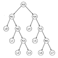
- the tree structure is composed of nodes. Also, the two lines coming out from the node are called branches. Nodes N0, N1, and the like having two branches are called internal nodes. Nodes L0, L1, etc. that do not have branches are called leaf nodes or simply leaves. Each leaf is mapped with one of the following coefficients. The node at the end of the branch is called a child. Further, FIG. 35A shows a case where there are eight leaves for simplicity.
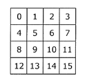
- FIG. 35B shows a plurality of coefficients obtained by conversion to a two-dimensional frequency space. Each of the plurality of coefficients is numbered from 0 to 15.
- FIG. 35C shows node types and leaf indexes representing the tree structure shown in FIG. 35A.
- the node type indicates whether the node is an internal node or a leaf node. If the node is an internal node, the node type is 0. If the node is a leaf node, the node type is 1.
- a plurality of node types corresponding to the plurality of nodes shown in FIG. 35A are arranged in the order of depth-first search from the start point of the tree structure.
- the node N0 that is the starting point is also called a root node. Since the root node is a node that is always provided in the tree structure, the root node is omitted in the node type of FIG. 35C.
- a plurality of node types are arranged from the node type of the node N1.
- the leaf index indicates the number of the frequency component mapped to the leaf node, more specifically, the number of the frequency component shown in FIG. 35B.
- leaf indexes corresponding to the plurality of leaf nodes shown in FIG. 35A are arranged in the order of L0 to L7.
- the tree structure in FIG. 35A is expressed as shown in FIG. 35C.
- frequency components with high appearance frequency are arranged as close as possible to the start node of the tree structure. Then, a plurality of nodes including the internal node and the leaf node are encoded in the order based on the depth-first search.
- the value of the inner node is encoded as “10”. If the internal node has left and right branches, that is, if at least one non-zero coefficient leaf exists at the end of both branches, the value of the internal node is encoded as “11”. When the inner node has only the right branch, that is, when at least one non-zero coefficient leaf exists at the tip of the right branch, the value of the inner node is encoded as “0”.
- This tree structure indicates the presence or absence of non-zero coefficients depending on the presence or absence of leaf nodes.
- achieves a high compression rate is produced
- the internal node When the value of the internal node is “10”, the internal node has only the left branch. In this case, there is no non-zero coefficient leaf at the tip of the right branch. When the value of the internal node is “11”, the internal node has both left and right branches. When the value of the internal node is “0”, a leaf having a non-zero coefficient exists only at the tip of the right branch. If there is no non-zero coefficient leaf at the end of any of the left and right branches, the internal node is not encoded. Therefore, there is no such case.
- the value of the decrypted internal node is checked. First, it is determined whether or not the left side of the internal node value is 1 (S1003). That is, this is equivalent to checking that the decoded value is either “10” or “11”.
- the left side of the value of the internal node is 1 (Yes in S1003), then the left child of the internal node is decoded (S1004).
- This decoding method is realized by recursively executing the flowchart of FIG. Next, it is determined whether or not the right side of the value of the internal node is 1 (S1005). This is equivalent to checking that the decoded value is “11”. If the right side of the value of the internal node is not 1 (No in S1005), the process ends.
- Patent Document 1 discloses an encoding method and a decoding method based on an encoding method using a tree structure.
- Patent Document 1 does not show a method for solving the deterioration of performance or a configuration for realizing high performance.
- an image decoding device and an image encoding device are often mounted so that processing of one macroblock is completed within a certain cycle.
- it is necessary to trace one or more internal nodes even if there is only one non-zero coefficient.
- an object of the present invention is to provide an image decoding apparatus that can suppress a decrease in processing efficiency due to the use of a tree structure.
- an image decoding apparatus is an image decoding apparatus that decodes an image from an encoded stream including coefficient data encoded using a tree structure, and uses the tree structure.
- a preprocessing unit that decodes the coefficient data encoded in a manner different from the tree structure and stores the coefficient data in a buffer; a decoding unit that reads the coefficient data from the buffer and decodes the image; Is provided.
- the image decoding apparatus can suppress a decrease in processing efficiency due to the use of a tree structure.
- the preprocessing unit stores the coefficient data and encoded information that is information included in the encoded stream and is different from the coefficient data in the buffer
- the decoding unit includes: The coefficient data and the encoded information may be read from the buffer and the image may be decoded.
- the image decoding apparatus can more appropriately separate the tree structure decoding process from other decoding processes. Therefore, waiting for processing is reduced.
- the preprocessing unit includes a tree structure decoding unit that decodes the coefficient data encoded using the tree structure, and an arrangement that rearranges the coefficient data decoded by the tree structure decoding unit in a predetermined order. You may provide the replacement part and the storage part which stores the said coefficient data rearranged by the said rearrangement part, and the said encoding information in the said buffer.
- the image decoding apparatus when decoding the tree structure, the image decoding apparatus according to the present invention can rearrange the coefficient data from the order depending on the tree structure to a predetermined order such as the frequency index order. Therefore, the image decoding apparatus does not need to rearrange the coefficient data in other decoding processes. Therefore, a reduction in processing efficiency is suppressed.
- the preprocessing unit further includes a coefficient encoding unit that encodes the coefficient data rearranged by the rearrangement unit in a format different from the tree structure, and the storage unit includes the coefficient encoding
- the coefficient data encoded by the unit and the encoded information may be stored in the buffer.
- the coefficient encoding unit converts the coefficient data rearranged by the rearrangement unit to H.264.
- the encoding may be performed by a method defined in the H.264 standard.
- H. H.264 decoding circuit can be used, and mounting becomes easy.
- the coefficient encoding unit is a combination of the number of consecutive zero coefficients included in the coefficient data rearranged by the rearrangement unit and the magnitude of non-zero coefficients included in the coefficient data.
- the coefficient data may be encoded.
- the coefficient data is encoded by an encoding method with a high compression rate. Therefore, the reduction of the buffer capacity and the reduction of the access bandwidth of the buffer are more appropriately realized.
- the preprocessing unit has a tree structure decoding unit that decodes the coefficient data encoded using the tree structure, and the coefficient data decoded by the tree structure decoding unit has a format different from the tree structure.
- a coefficient encoding unit that encodes the data, and a storage unit that stores the coefficient data encoded by the coefficient encoding unit and the encoded information in the buffer.
- the image may be decoded by reading the coefficient data and the encoding information, decoding the read coefficient data, and rearranging the decoded coefficient data in a predetermined order.
- the circuit area can be reduced by changing the order of the coefficient data using a buffer used for inverse quantization or inverse frequency conversion in the decoding unit.
- the preprocessing unit further includes an arithmetic decoding unit that arithmetically decodes the coefficient data that has been arithmetically encoded and the encoded information that has been arithmetically encoded, and the coefficient that has been arithmetically decoded by the arithmetic decoding unit
- An inverse binarization unit that inversely binarizes data and the encoded information that has been arithmetically decoded by the arithmetic decoding unit, and encodes the encoded information that has been binarized by the inverse binarization unit
- a re-encoding unit that decodes the coefficient data from the coefficient data inversely binarized by the inverse binarization unit, and the storage unit encodes the coefficient encoding
- the coefficient data encoded by the unit and the encoded information encoded by the re-encoding unit may be stored in the buffer.
- an image encoded using both arithmetic coding and coefficient coding using a tree structure is efficiently decoded.
- Arithmetic coding and coefficient coding using a tree structure are often used in combination to improve the compression rate. With the above configuration, efficient decoding corresponding to such a combination becomes possible.
- the inverse binarization unit inverse binarizes only the first information that is information used in the preprocessing unit among the encoded information arithmetically decoded by the arithmetic decoding unit, and the re-encoding unit
- the first information is encoded by binarizing the first information that has been de-binarized by the de-binarization unit, and the storage unit is encoded by the coefficient encoding unit Information included in the coefficient data, the first information encoded by the re-encoding unit, and the encoded information arithmetically decoded by the arithmetic decoding unit, the information being different from the first information
- the second information may be stored in the buffer.
- the arithmetic decoding unit is H.264.
- the coefficient data and the encoded information that are arithmetically encoded by the arithmetic encoding method defined by the H.264 standard may be arithmetically decoded.
- H. H.264 decoding circuit can be used, and mounting becomes easy.
- the image decoding device may include the buffer.
- the image decoding apparatus can separate the tree-structured decoding process from other decoding processes using the buffer of the image decoding apparatus.
- An image encoding device is an image encoding device that encodes an image and generates an encoded stream including coefficient data encoded using a tree structure, and encodes the image. Generating the coefficient data, storing the coefficient data in a buffer in a format different from the tree structure, reading the coefficient data from the buffer, and using the tree structure to convert the coefficient data
- a post-processing unit that generates the encoded stream including the coefficient data that is encoded and encoded using the tree structure.
- the image encoding apparatus can suppress a decrease in processing efficiency due to the use of the tree structure.
- An image decoding method is an image decoding method for decoding an image from an encoded stream including coefficient data encoded using a tree structure, and the image decoding method is encoded using the tree structure.
- the method may include a preprocessing step of decoding the coefficient data and storing the coefficient data in a buffer in a format different from the tree structure, and a decoding step of reading the coefficient data from the buffer and decoding the image.
- the image decoding apparatus can be realized as an image decoding method.
- An image encoding method is an image encoding method for generating an encoded stream including coefficient data encoded using a tree structure by encoding an image, wherein the image is encoded. Generating the coefficient data, storing the coefficient data in a buffer in a format different from that of the tree structure, reading the coefficient data from the buffer, and converting the coefficient data using the tree structure And a post-processing step of generating the encoded stream including the coefficient data encoded and encoded using the tree structure.
- the image encoding device can be realized as an image encoding method.
- the recording medium according to the present invention is a non-transitory computer-readable recording medium in which a program for decoding an image is recorded from an encoded stream including coefficient data encoded using a tree structure. And decoding the coefficient data encoded using the tree structure, and storing the coefficient data in a buffer in a format different from the tree structure; and reading the coefficient data from the buffer; It may be a non-transitory computer-readable recording medium in which a program for causing a computer to execute the decoding step for decoding the image is recorded.
- the image decoding method can be realized as a recording medium.
- the recording medium according to the present invention is a non-transitory computer-readable recording program for encoding an image and generating an encoded stream including coefficient data encoded using a tree structure.
- An encoding step of generating the coefficient data by encoding the image and storing the coefficient data in a buffer in a format different from the tree structure, and reading the coefficient data from the buffer A program for causing a computer to execute a post-processing step of encoding the coefficient data using the tree structure and generating the encoded stream including the coefficient data encoded using the tree structure It may be a non-transitory computer-readable recording medium.
- the image encoding method can be realized as a recording medium.
- An integrated circuit is an integrated circuit that decodes an image from an encoded stream including coefficient data encoded using a tree structure, and the coefficient encoded using the tree structure
- a preprocessing unit that decodes data and stores the coefficient data in a buffer in a format different from the tree structure, and a decoding unit that reads the coefficient data from the buffer and decodes the image may be provided.
- the image decoding apparatus can be realized as an integrated circuit.
- An integrated circuit is an integrated circuit that encodes an image to generate an encoded stream including coefficient data encoded using a tree structure, and encodes the image to generate the encoded stream. Generating coefficient data, storing the coefficient data in a buffer in a format different from the tree structure, reading the coefficient data from the buffer, encoding the coefficient data using the tree structure, A post-processing unit that generates the encoded stream including the coefficient data encoded using a tree structure.
- the image encoding device can be realized as an integrated circuit.
- a reduction in processing efficiency due to the use of a tree structure is suppressed. That is, it is possible to use an encoding method with high encoding efficiency while suppressing a decrease in processing efficiency.
- FIG. 1 is a block diagram showing a configuration of an image decoding apparatus according to Embodiment 1.
- FIG. 2 is a block diagram showing a configuration of the decoding unit according to the first embodiment.
- FIG. 3 is an explanatory diagram showing the structure of the encoded stream.
- FIG. 4A is a diagram showing a tree structure.
- FIG. 4B is a diagram illustrating a block of frequency coefficients.
- FIG. 4C is a diagram illustrating a representation format of a tree structure.
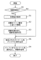
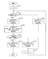
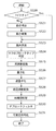
- FIG. 5 is a flowchart showing the operation of the image decoding apparatus according to the first embodiment.
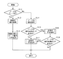
- FIG. 6 is a flowchart showing the operation of the tree structure decoding unit according to the first embodiment.
- FIG. 1 is a block diagram showing a configuration of an image decoding apparatus according to Embodiment 1.
- FIG. 2 is a block diagram showing a configuration of the decoding unit according to the first embodiment.
- FIG. 3 is an explanatory diagram showing the structure of the encoded stream.
- FIG. 7A is a flowchart showing the operation of the rearrangement unit according to Embodiment 1.
- FIG. 7B is an explanatory diagram illustrating an operation of the rearrangement unit according to Embodiment 1.
- FIG. 8 is an explanatory diagram showing a coding method of the coefficient coding unit according to the first embodiment.
- FIG. 9 is a flowchart showing the operation of the coefficient encoding unit according to Embodiment 1.
- FIG. 10 is a flowchart showing the operation of the coefficient encoding unit according to Embodiment 1.
- FIG. 11 is a flowchart showing the operation of the decoding unit according to the first embodiment.
- FIG. 12 is a block diagram showing a configuration of a modified example of the image decoding apparatus according to Embodiment 1.
- FIG. 12 is a block diagram showing a configuration of a modified example of the image decoding apparatus according to Embodiment 1.
- FIG. 12 is a block diagram showing a configuration of a modified example of the image decoding apparatus
- FIG. 13A is a block diagram illustrating a characteristic configuration of the image decoding apparatus.
- FIG. 13B is a flowchart showing a characteristic operation of the image decoding apparatus.
- FIG. 14 is a block diagram illustrating a configuration of the image decoding apparatus according to the second embodiment.
- FIG. 15 is a block diagram showing a configuration of a decoding unit according to the second embodiment.
- FIG. 16 is a flowchart showing an operation of the image decoding apparatus according to the second embodiment.
- FIG. 17 is an explanatory diagram illustrating an encoding method of a coefficient encoding unit according to Embodiment 2.
- FIG. 18 is a flowchart showing the operation of the coefficient coding unit according to the second embodiment.
- FIG. 19 is a block diagram illustrating a configuration of the image decoding apparatus according to the third embodiment.
- FIG. 20 is a flowchart showing an operation of the image decoding apparatus according to the third embodiment.
- FIG. 21 is a block diagram showing a configuration of an image decoding apparatus according to Embodiment 4.
- FIG. 22 is a flowchart showing the operation of the image decoding apparatus according to the fourth embodiment.
- FIG. 23 is a block diagram showing a configuration of an image coding apparatus according to Embodiment 5.
- FIG. 24 is a block diagram showing a configuration of an encoding unit according to Embodiment 5.
- FIG. 25 is a flowchart showing the operation of the image coding apparatus according to Embodiment 5.
- FIG. 20 is a flowchart showing an operation of the image decoding apparatus according to the third embodiment.
- FIG. 21 is a block diagram showing a configuration of an image decoding apparatus according to Embodiment 4.
- FIG. 22 is a flowchart showing the operation of the
- FIG. 26 is a flowchart showing the operation of the encoding unit according to Embodiment 5.
- FIG. 27A is a block diagram illustrating a characteristic configuration of the image encoding device.
- FIG. 27B is a flowchart showing a characteristic operation of the image encoding device.
- FIG. 28 is an overall configuration diagram of a content supply system that realizes a content distribution service.
- FIG. 29 is an overall configuration diagram of a digital broadcasting system.
- FIG. 30 is a block diagram illustrating a configuration example of a television.
- FIG. 31 is a block diagram illustrating a configuration example of an information reproducing / recording unit that reads and writes information from and on a recording medium that is an optical disk.
- FIG. 32 is a diagram illustrating a structure example of a recording medium that is an optical disk.
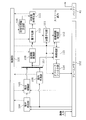
- FIG. 33 is a configuration diagram illustrating a configuration example of an integrated circuit that implements image decoding processing.
- FIG. 34 is a configuration diagram illustrating a configuration example of an integrated circuit that implements image encoding processing and image decoding processing.
- FIG. 35A is a diagram showing a tree structure.
- FIG. 35B is a diagram illustrating a block of frequency coefficients.
- FIG. 35C is a diagram illustrating a representation format of a tree structure.
- FIG. 36 is a flowchart showing a conventional image decoding process.
- the image decoding apparatus performs tree-structure decoding prior to image decoding. Then, the image decoding apparatus is H.264. The coefficients are encoded again according to the coefficient encoding method of the H.264 / AVC standard. And the decoding part of an image decoding apparatus decodes an image from the encoded coefficient. Thereby, since the image decoding apparatus does not need to decode a tree structure in a decoding part, the performance of a decoding part can be improved.
- decoding the data usually means generating the original data by decoding the encoded data.
- decoding an image means generating an original image by decoding an encoded image.
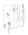
- FIG. 1 is a block diagram of an image decoding apparatus according to the present embodiment.
- the image decoding apparatus according to the present embodiment includes a preprocessing unit 6, a buffer 4, and a decoding unit 5.
- the preprocessing unit 6 includes a tree structure decoding unit 1, a rearrangement unit 2, a coefficient encoding unit 3, and a storage unit 33.
- the tree structure decoding unit 1 performs tree structure decoding.
- the rearrangement unit 2 rearranges the coefficient information.
- the coefficient encoding unit 3 encodes the coefficient again.
- the buffer 4 is a storage unit for holding a stream.
- the storage unit 33 stores the stream in the buffer 4.
- the decoding unit 5 performs image decoding processing.
- the decoding unit 5 shown in FIG. 1 is configured by the block diagram shown in FIG. In FIG. 2, the decoding unit 5 includes a control unit 11, a variable length decoding unit 13, an inverse quantization unit 14, an inverse frequency conversion unit 15, an in-plane prediction unit 16, a motion vector calculation unit 17, a motion compensation unit 18, and a switch 19.
- the reconfiguration unit 20 and the deblock filter unit 21 are provided.
- the buffer 4 and the frame memory 12 may be inside the decoding unit 5 or outside.
- the control unit 11 controls the entire decoding unit 5.
- the buffer 4 holds the input encoded stream.
- the frame memory 12 holds the decoded image data.
- the variable length decoding unit 13 reads the bit stream and decodes the variable length code.
- the inverse quantization unit 14 performs inverse quantization.
- the inverse frequency converter 15 performs inverse frequency conversion.
- the in-plane prediction unit 16 performs in-plane prediction (also referred to as intra prediction) and generates a predicted image.
- the motion vector calculation unit 17 calculates a motion vector.
- the motion compensation unit 18 performs motion compensation and generates a predicted image.
- the switch 19 switches the predicted image.
- the reconstruction unit 20 generates a decoded image from the difference image subjected to inverse frequency conversion and the predicted image.
- the deblocking filter unit 21 removes block noise from the reconstructed image and improves the image quality.
- FIG. 3 shows a configuration of an encoded stream decoded by the image decoding apparatus according to the present embodiment.
- the encoded stream includes a start code, a sequence header, a picture header, a slice header, and slice data.
- the slice data is further composed of one or more macroblock data.
- the macroblock data is composed of coding information indicating the macroblock type, motion vector information, quantization information, and the like, and coefficient information.
- the part other than the coefficient information is H.264.
- the format is the same as the H.264 / AVC standard.
- the coefficient information is encoded by the method using the binary tree structure shown in Patent Document 1.
- 4A, 4B, and 4C are diagrams for explaining the method.
- the tree structure is composed of nodes. Also, the two lines coming out from the node are called branches. Nodes N0, N1, and the like having two branches are called internal nodes. Nodes L0, L1, etc. that do not have branches are called leaf nodes or simply leaves. Each leaf is mapped with one of the following coefficients. The node at the end of the branch is called a child. Further, FIG. 4A shows a case where there are eight leaves for simplicity.
- FIG. 4B shows a plurality of coefficients obtained by conversion to a two-dimensional frequency space. Each of the plurality of coefficients is numbered from 0 to 15.
- FIG. 4C shows a node type and a leaf index representing the tree structure shown in FIG. 4A.
- the node type indicates whether the node is an internal node or a leaf node. If the node is an internal node, the node type is 0. If the node is a leaf node, the node type is 1.
- a plurality of node types corresponding to the plurality of nodes shown in FIG. 4A are arranged in the order of depth-first search from the start point of the tree structure.
- the node N0 that is the starting point is also called a root node. Since the root node is a node that is always provided in the tree structure, the root node is omitted in the node type of FIG. 4C.
- a plurality of node types are arranged from the node type of the node N1.
- the leaf index indicates the number of the frequency component mapped to the leaf node, more specifically, the number of the frequency component shown in FIG. 4B.
- leaf indexes corresponding to the plurality of leaf nodes shown in FIG. 4A are arranged in the order of L0 to L7.
- the tree structure of FIG. 4A is expressed as shown in FIG. 4C.
- frequency components with high appearance frequency are arranged as close as possible to the start node of the tree structure. Then, a plurality of nodes including the internal node and the leaf node are encoded in the order based on the depth-first search.
- the value of the inner node is encoded as “10”. If the internal node has left and right branches, that is, if at least one non-zero coefficient leaf exists at the end of both branches, the value of the internal node is encoded as “11”. When the inner node has only the right branch, that is, when at least one non-zero coefficient leaf exists at the tip of the right branch, the value of the inner node is encoded as “0”.
- This tree structure indicates the presence or absence of non-zero coefficients depending on the presence or absence of leaf nodes.
- achieves a high compression rate is produced
- the tree structure decoding unit 1 determines whether or not the information acquired from the encoded stream is coefficient information (S5). If the information acquired from the encoded stream is not coefficient information (No in S5), the storage unit 33 performs stream storage processing (S6).
- the tree structure decoding unit 1 decodes the coefficient information encoded in the tree structure (S1).
- the rearrangement unit 2 stores the coefficient information obtained by decoding the tree-structured coefficient information in a storage unit such as a memory according to the leaf number (S2).
- the coefficient encoding unit 3 reads the coefficient information in the order of frequency index and re-encodes (S3).
- the storage unit 33 combines the coefficient information and information other than the coefficient information included in the encoded stream, and writes them into the buffer 4 as a new stream (S6).
- a typical example of information other than coefficient information is the encoded information shown in FIG.
- Information other than the coefficient information may include header information such as a sequence header, a picture header, and a slice header.
- the decoding unit 5 reads the stream from the buffer 4 and decodes the image (S4).
- the tree structure decoding unit 1 determines whether or not the node is a leaf (S11). If the node is a leaf (Yes in S11), there are coefficients mapped to that leaf. Therefore, the tree structure decoding unit 1 decodes the coefficient (S12). Then, the tree structure decoding unit 1 outputs the decoded coefficient and the corresponding leaf number to the rearrangement unit 2 (S13). If the node is not a leaf, that is, if the node is an internal node (No in S11), the tree structure decoding unit 1 decodes the value of the internal node (S14).
- the internal node When the value of the internal node is “10”, the internal node has only the left branch. In this case, there is no non-zero coefficient leaf at the tip of the right branch. When the value of the internal node is “11”, the internal node has both left and right branches. When the value of the internal node is “0”, a leaf having a non-zero coefficient exists only at the tip of the right branch. If there is no non-zero coefficient leaf at the end of any of the left and right branches, the internal node is not encoded. Therefore, there is no such case.
- the tree structure decoding unit 1 checks the value of the decoded internal node. First, the tree structure decoding unit 1 determines whether or not the left side of the value of the internal node is 1 (S15). That is, this is equivalent to checking that the decoded value is either “10” or “11”.
- the tree structure decoding unit 1 then decodes the left child of the internal node (S16). This decoding method is realized by recursively executing the flowchart of FIG. Next, the tree structure decoding unit 1 determines whether or not the right side of the value of the internal node is 1 (S18). This is equivalent to checking that the decoded value is “11”. When the right side of the value of the internal node is not 1 (No in S18), the tree structure decoding unit 1 ends the process.
- the tree structure decoding unit 1 decodes the right child of the internal node. (S17). This decoding method is realized by recursively executing the flowchart of FIG.
- each leaf number and coefficient value are output by the output process (S13) in the flowchart of FIG. Therefore, the rearrangement unit 2 first calculates a frequency index from the leaf number (S21).
- the rearrangement unit 2 can easily calculate the frequency index by using the table shown in FIG. 7B. This table can be created with information given prior to decoding in a format such as the leaf index values shown in FIG. 4C.
- the rearrangement unit 2 writes the coefficient value in a storage unit such as a memory (S22).
- a storage unit such as a memory (S22).
- This process can be easily realized, for example, by writing a coefficient value in a memory having a frequency index value as an address.
- the rearrangement unit 2 can store the value of each frequency component in the storage unit in the order of the frequency index.
- the rearrangement unit 2 can rearrange the coefficient data in a predetermined order by executing the coefficient storage process described above.
- the predetermined order is a frequency index order indicating a frequency height, and is typically an order from a low frequency to a high frequency.
- the predetermined order is an order corresponding to a so-called zigzag scan, and 0, 1, 4, 8, 5, 2, 3,..., Using the numbers shown in FIG. It is expressed as 11, 14, 15.
- 0 is a number corresponding to the lowest frequency
- 15 is a number corresponding to the highest frequency.
- the rearrangement unit 2 may rearrange the coefficient data into a two-dimensional table format such as the frequency block shown in FIG. 4B.
- FIG. 5 is a syntax structure itself showing a coding method of coefficients used in CABAC (Context Adaptive Binary Arithmetic Coding) used in the H.264 / AVC standard. In this embodiment, a case of re-encoding to this format is shown.
- CABAC Context Adaptive Binary Arithmetic Coding
- the coefficient encoding unit 3 substitutes 0 for a variable i indicating a frequency index (S41).
- the coefficient encoding unit 3 determines whether or not the coefficient of the variable i indicating the frequency index is 0 (S42).
- the coefficient encoding unit 3 encodes coeff_abs_level_minus1 and coeff_sign_flag for the coefficient whose frequency index is numCoef-1 (S61).
- coeff_abs_level_minus1 is a value obtained by subtracting 1 from the coefficient value to calculate an absolute value.
- coeff_sign_flag is a sign of the coefficient value.
- the coefficient encoding unit 3 sets numCoeff-2 to the variable i (S62). Next, the coefficient encoding unit 3 determines whether or not the significant_coeff_flag corresponding to the variable i is 1 (S63).
- the coefficient encoding unit 3 encodes coeff_abs_level_minus1 and coeff_sign_flag of the coefficient corresponding to the variable i (S64). If the significant_coeff_flag is not 1 (No in S63), the coefficient encoding unit 3 performs the following process without doing anything.
- the coefficient encoding unit 3 subtracts 1 from the variable i (S65).
- the coefficient encoding unit 3 ends the process.
- the coefficient encoding unit 3 returns to the determination process (S63) for determining whether the significant_coeff_flag corresponding to the variable i is 1, and continues the process.
- variable length decoding unit 13 performs variable length decoding on the input encoded stream (S101).
- the variable length decoding unit 13 outputs encoding information such as a macroblock type, an intra prediction (intra prediction) mode, motion vector information, and a quantization parameter, and coefficient information corresponding to each pixel data.
- the motion vector calculation unit 17 calculates a motion vector by performing a motion vector calculation using the encoded information (S103).
- a motion vector is calculated from a predicted motion vector determined by a median value of three surrounding motion vectors mvA, mvB, and mvC. Specifically, a motion vector is obtained by adding the predicted motion vector and motion vector information (motion vector difference value) included in the encoded stream.
- the encoded information is output to the control unit 11 and then input to each processing unit.
- the coefficient information is output to the inverse quantization unit 14 which is the next processing unit.
- the inverse quantization unit 14 performs an inverse quantization process (S104).
- the reverse frequency conversion unit 15 performs reverse frequency conversion (S105).
- the control unit 11 determines whether the decoding target macroblock is an inter macroblock or an intra macroblock (S106).
- the motion vector calculation unit 17 inputs the calculated motion vector to the motion compensation unit 18.
- the motion compensation unit 18 reads a reference image indicated by the motion vector from the frame memory 12 (S107).
- the motion compensation unit 18 uses the read reference image to generate a predicted image with 1/2 pixel accuracy or 1/4 pixel accuracy (S108).
- the in-plane prediction unit 16 performs an in-plane prediction process to obtain a predicted image. Generate (S109). The selection of whether or not this is an inter macro block may be performed by the switch 19 in the configuration diagram of FIG.
- the reconstruction unit 20 generates a decoded image by adding the obtained predicted image and the difference image output from the inverse frequency transform unit 15 (S110).
- the deblock filter unit 21 performs a deblock filter process for reducing block noise on the decoded image obtained by the reconstructing unit 20.
- the deblock filter unit 21 stores the image obtained by the deblock filter process in the frame memory 12 (S111). This completes the decoding operation for one macroblock.
- the pre-processing unit 6 is a processing unit that requires performance according to the bit rate of the encoded stream such as the input stream and the output stream. That is, the size of the encoded stream including coefficient data encoded using the tree structure varies depending on the ratio of the non-zero coefficient and the zero coefficient.
- the preprocessing unit 6 requires performance according to the varying size.
- the tree structure decoding unit 1 of the preprocessing unit 6 follows the tree structure for each bit indicating the presence or absence of a branch of each node. In the encoded stream, 1 bit or more is used for the non-zero coefficient. Therefore, the tree structure decoding unit 1 may execute the tree structure decoding process in one cycle per bit or in a fixed cycle of more.
- the rearrangement unit 2 of the preprocessing unit 6 stores only non-zero coefficients in a storage unit such as a memory. At least one bit is used for the non-zero coefficient. Therefore, the rearrangement unit 2 may execute the coefficient data rearrangement process in one cycle per bit or a fixed cycle equal to or more than the tree structure decoding unit 1.
- the coefficient encoding unit 3 of the preprocessing unit 6 encodes only non-zero coefficients. Therefore, the coefficient encoding unit 3 requires performance according to the bit rate of the encoded stream.
- the components included in the preprocessing unit 6 are processing units that require performance according to the bit rate of the encoded stream. Therefore, the preprocessing unit 6 needs performance according to the bit rate of the encoded stream.
- the decoding unit 5 is a processing unit that requires performance according to the number of pixels of the image to be decoded.
- the decoding target macroblock is an inter macroblock and a motion vector exists
- the motion compensation unit 18 of the decoding unit 5 performs a motion compensation process on all the pixels included in the block.
- the decoding unit 5 is a processing unit that does not depend on the bit amount of the encoded stream and requires performance according to the number of pixels of the image to be decoded.
- the preprocessing unit 6 and the decoding unit 5 are required to have different processing performance. Therefore, in the image decoding apparatus according to the present embodiment, the preprocessing unit 6 and the decoding unit 5 are arranged separately and are configured to operate in cooperation via the buffer 4.
- FIG. 12 is a block diagram showing a configuration of a modified example of the image decoding apparatus according to Embodiment 1.
- the image decoding apparatus illustrated in FIG. 12 includes a preprocessing unit 6, a buffer 4, and a decoding unit 5.
- the preprocessing unit 6 includes a tree structure decoding unit 1 and a storage unit 33.
- the storage unit 33 stores the coefficient data decoded by the tree structure decoding unit 1 in the buffer 4.
- the storage unit 33 stores the coefficient data in the buffer 4 so that the coefficient data is in the frequency index order. That is, the storage unit 33 has the function of the rearrangement unit 2 shown in FIG.
- the storage unit 33 stores the decoded coefficient data in the buffer 4 without encoding the decoded coefficient data, that is, without compressing the decoded coefficient data.
- the decoding unit 5 reads the coefficient data from the buffer 4 and decodes the image. As a result, a larger capacity is required for the buffer 4, but it is not necessary for the decoding unit 5 to decode the coefficient data, so that the processing efficiency is improved.
- the storage unit 33 may store the coefficient data in the buffer 4 not in the frequency index order but in the leaf number order. Then, the decoding unit 5 may read the coefficient data from the buffer 4 in order of frequency index based on the correspondence table shown in FIG. 7B. That is, the decoding unit 5 may have the function of the rearrangement unit 2 shown in FIG.
- FIG. 13A is a block diagram showing a characteristic configuration of the image decoding apparatus according to Embodiment 1.
- the image decoding device 61 illustrated in FIG. 13A includes a preprocessing unit 6 and a decoding unit 5.
- the buffer 4 exists outside the image decoding device 61. That is, the buffer 4 may not be included in the image decoding device 61.
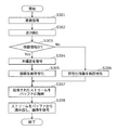
- FIG. 13B is a flowchart showing a characteristic operation of the image decoding apparatus shown in FIG. 13A.
- the preprocessing unit 6 decodes coefficient data included in the encoded stream and encoded using a tree structure.
- the preprocessing unit 6 performs variable length decoding on the coefficient data.
- the preprocessing unit 6 stores the coefficient data in the buffer 4 in a format different from the tree structure (S31).
- the decoding unit 5 reads the coefficient data from the buffer 4 and decodes the image (S32). Thereby, the image decoding apparatus 61 decodes an image from the encoding stream containing the coefficient data encoded using the tree structure.
- the buffer 4 preferably has a sufficient storage capacity for holding coefficient data.
- the buffer 4 when the decoding unit 5 decodes an image for each block, the buffer 4 preferably has a storage capacity capable of holding a plurality of blocks.
- the buffer 4 preferably has a storage capacity of at least twice the size of the coefficient data processed by one frequency conversion or one inverse frequency conversion.
- the buffer 4 may have a storage capacity capable of holding a plurality of blocks compressed by encoding.
- the buffer 4 can store a plurality of coefficient blocks. Therefore, the waiting time for processing is reduced, and the decoding process is efficiently executed.
- the image decoding apparatus first decodes coefficient data having a tree structure, re-encodes the coefficient data by another method, and stores the generated stream in the buffer 4. Thereafter, the image decoding device reads the stream from the buffer 4 and the decoding unit 5 decodes the image. Thereby, the image decoding apparatus does not need to follow the tree structure by the decoding unit 5, and can realize high performance.
- decoding of the tree structure is a process executed according to the number of bits of the encoded stream. Therefore, high performance can be easily realized by performing processing separately from the decoding unit 5 that performs processing according to the number of pixels.
- the processing time from the start of processing to the completion of processing varies greatly depending on the number of non-zero coefficients.
- such fluctuations in processing time are relatively small.
- these decoding processes are executed as a series of operations, a time during which no other decoding process is executed occurs due to the influence of the tree-structure decoding process. Therefore, in this case, the processing efficiency is lowered.
- the image decoding apparatus can suppress a decrease in processing efficiency due to the use of a tree structure.
- the decoding unit 5 can decode an encoded image without using a tree structure. Therefore, the image decoding apparatus according to the present embodiment can decode both an image encoded using a tree structure and an image encoded without using a tree structure.
- the image decoding apparatus operates sequentially.
- the image decoding apparatus may execute each process on different data in parallel as long as necessary information is prepared.
- the image decoding apparatus is H.264.
- the coefficient data was re-encoded by the CABAC encoding method shown in the H.264 / AVC standard.
- the image decoding apparatus may re-encode the coefficient data by the CAVLC method or the encoding method shown in the MPEG2 standard.
- Run-length encoding is an encoding method that encodes coefficient data in a format that combines the number of zero coefficients (ie, runs) and the value of non-zero coefficients (ie, levels).
- data generated by run-length encoding is further encoded by Huffman encoding. If the coefficient data is encoded using runs, the zero coefficient processing cycle is reduced.
- the format of information other than the portion indicating the presence / absence of coefficients is H.264.
- the format is the same as the H.264 / AVC standard.
- the format of these information may be based on other standards such as MPEG2 or VC-1.
- the format of these information does not need to be based on the existing encoding standard.
- the image decoding apparatus changes the coefficient data in the order of the frequency index when the rearrangement unit 2 writes to the memory.
- the image decoding apparatus may change the coefficient data in order of the frequency index when the rearrangement unit 2 reads from the memory.
- a conversion table from a frequency index to a leaf number may be used contrary to the present embodiment.
- control unit or the like is not described in the preprocessing unit 6, but a block, a processor, a program module, or the like that performs timing control or the like may exist in the preprocessing unit 6.
- control part 11 of the decoding part 5 may serve as the function.
- the means for realizing the present embodiment may be hardware or software that is operated by a processor.
- the block for storing data may have any configuration such as a memory or a flip-flop.
- the image decoding apparatus re-encodes only coefficient information.
- the image decoding apparatus may re-encode coefficient information together with all or part of other information.
- the storage unit 33 combines coefficient information and other information into a single stream.
- the image decoding apparatus may be provided with a plurality of buffers 4 so as to deliver coefficient information and other information separately to the decoding unit 5.
- the image decoding apparatus performs re-encoding in the preprocessing.
- the image decoding apparatus may write the decoded encoded information and coefficient information into the buffer 4 as they are.
- the buffer 4 requires a larger capacity, and a larger bandwidth is required for writing and reading the buffer 4.
- Embodiment 2 (2-1. Overview) An overview of the image decoding apparatus according to the present embodiment will be described.
- the image decoding apparatus according to the present embodiment performs tree-structure decoding prior to image decoding.
- the preprocessing unit does not perform conversion from the leaf number order to the frequency index order.
- the preprocessing unit encodes the coefficient data with the changed encoding method.
- the decoding unit performs conversion from the leaf number order to the frequency index order. Thereby, performance is maintained and a circuit scale is reduced.
- FIG. 14 is a block diagram of the image decoding apparatus according to the present embodiment.
- the image decoding apparatus according to the present embodiment includes a preprocessing unit 26, a buffer 4, and a decoding unit 27.
- the preprocessing unit 26 includes a tree structure decoding unit 1, a coefficient encoding unit 28, and a storage unit 33.
- the tree structure decoding unit 1 performs tree structure decoding.
- the coefficient encoding unit 28 encodes the coefficient again.
- the buffer 4 is a storage unit for holding a stream.
- the storage unit 33 stores the stream in the buffer 4.
- the decoding unit 27 performs image decoding processing.
- FIG. 15 shows a configuration of the decoding unit 27 in FIG.
- the decoding unit 27 of the present embodiment includes a rearrangement unit 29. All other components are the same as those in the first embodiment shown in FIG.
- the configuration of the encoded stream decoded by the image decoding apparatus according to the present embodiment and the coefficient information encoding method are the same as those of the first embodiment shown in FIG. 3, FIG. 4A, FIG. 4B, and FIG. It is the same as the method.
- the tree structure decoding unit 1 determines whether or not the information acquired from the encoded stream is coefficient information (S204). If the information acquired from the encoded stream is not coefficient information (No in S204), the storage unit 33 performs stream storage processing (S205).
- the tree structure decoding unit 1 decodes the coefficient information encoded in the tree structure (S201).
- the coefficient encoding unit 28 re-encodes the coefficient information obtained by decoding the coefficient information of the tree structure (S202).
- the storage unit 33 combines the coefficient information and other encoded information and writes them as a stream in the buffer 4 (S205).
- the decoding unit 27 reads the stream from the buffer 4 and decodes the image (S203).
- the rearrangement unit 2 converts the coefficients output in the order of the leaf numbers in the order of the frequency index. Therefore, the coefficient encoding unit 3 cannot start re-encoding until all the leaf number coefficients are output. However, in the present embodiment, the coefficient encoding unit 28 re-encodes the coefficients output by the tree structure decoding unit 1 in the order of the leaf numbers.
- FIG. 17 shows the syntax of re-encoded coefficients according to the present embodiment.
- the coefficient encoding unit 28 substitutes 0 for a variable j indicating a leaf number (S211).
- the coefficient encoding unit 28 checks whether or not the coefficient of the variable j indicating the leaf number is 0 (S212).
- the operation of the image decoding process (S203) in the flowchart of FIG. 16 will be described.
- the operation of the image decoding process (S203) is substantially the same as that of the first embodiment shown in FIG. 11, but the operation of the variable length decoding process (S101) is different.
- the rearrangement unit 29 rearranges the coefficient data.
- the rearrangement unit 29 rearranges the coefficient data by storing the coefficient data decoded in the leaf number order in the memory in the frequency index order. At that time, the rearrangement unit 29 calculates the frequency index from the leaf number according to the table shown in FIG. 7B, similarly to the rearrangement unit 2 of the first embodiment. Then, rearrangement unit 29 stores the coefficients in the memory according to the frequency index obtained by the calculation.
- the inverse quantization unit 14 and the inverse frequency transform unit 15 can read the coefficients in the order of the frequency index and perform the quantization and inverse frequency transform processing.
- the inverse frequency transform unit 15 performs the inverse frequency transform process after the variable length decoding unit 13 outputs all the coefficient data originally necessary for the inverse frequency transform process. Therefore, the inverse frequency conversion unit 15 has a storage element such as a memory for storing coefficient data. Therefore, the rearrangement unit 29 according to the present embodiment can be implemented without increasing the circuit scale by using the memory that originally exists.
- the image decoding apparatus first decodes coefficient data having a tree structure. Then, the image decoding apparatus re-encodes the coefficient data by another method and stores the stream obtained by the re-encoding in the buffer 4. Thereafter, the image decoding apparatus decodes the image by the decoding unit 27. Thereby, the image decoding apparatus does not need to follow the tree structure in the decoding unit 27, and can improve the performance.
- the preprocessing unit 26 since the conversion from the leaf number to the frequency index is not performed by the preprocessing unit 26, the preprocessing unit 26 does not need a rearrangement unit. Therefore, the image decoding apparatus can reduce the delay caused by the preprocessing unit 26 and reduce the circuit scale of the preprocessing unit 26.
- the image decoding apparatus operates sequentially.
- the image decoding apparatus may execute each process on different data in parallel as long as necessary information is prepared.
- the image decoding apparatus is H.264.
- the coefficient data was re-encoded by a method in which the CABAC encoding method shown in the H.264 / AVC standard was changed.
- the image decoding apparatus may re-encode the coefficient data by the CAVLC method or the encoding method shown in the MPEG2 standard.
- Run-length encoding is an encoding method that encodes coefficient data in a format that combines the number of zero coefficients (ie, runs) and the value of non-zero coefficients (ie, levels).
- data generated by run-length encoding is further encoded by Huffman encoding. If the coefficient data is encoded using runs, the zero coefficient processing cycle is reduced.
- the format of information other than the portion indicating the presence / absence of coefficients is H.264.
- the format is the same as the H.264 / AVC standard.
- the format of these information may be based on other standards such as MPEG2 or VC-1.
- the format of these information does not need to be based on the existing encoding standard.
- the image decoding apparatus changes the coefficient data in the order of the frequency index when the rearrangement unit 29 of the decoding unit 27 writes to the memory.
- the image decoding apparatus may change the coefficient data in order of frequency index when reading from the memory.
- Such rearrangement may be performed at the time of reading by the inverse quantization unit 14 or the inverse frequency conversion unit 15. In such a case, a conversion table from a frequency index to a leaf number may be used contrary to the present embodiment.
- control unit or the like is not described in the preprocessing unit 26, but a block, a processor, a program module, or the like that performs timing control or the like may exist in the preprocessing unit 26.
- control part 11 of the decoding part 27 may serve as the function.
- the means for realizing the present embodiment may be hardware or software that is operated by a processor.
- the block for storing data may have any configuration such as a memory or a flip-flop.
- the image decoding apparatus re-encodes only coefficient information.
- the image decoding apparatus may re-encode coefficient information together with all or part of other information.
- the storage unit 33 combines coefficient information and other information into a single stream.
- the image decoding apparatus may be provided with a plurality of buffers 4 to separately deliver coefficient information and other information to the decoding unit 27.
- the image decoding apparatus performs re-encoding in the preprocessing.
- the image decoding apparatus may write the decoded encoded information and coefficient information into the buffer 4 as they are.
- the buffer 4 requires a larger capacity, and a larger bandwidth is required for writing and reading the buffer 4.
- the image decoding apparatus first performs arithmetic code decoding and inverse binarization. Next, the image decoding apparatus performs tree-structure decoding at a stage prior to image decoding. Then, the image decoding apparatus re-encodes the coefficients obtained by decoding the tree structure, and then decodes the image by the decoding unit. Thereby, the performance improvement by arithmetic decoding and the performance improvement by a tree structure are implement
- FIG. 19 is a block diagram of the image decoding apparatus according to the present embodiment.
- the image decoding apparatus according to the present embodiment includes a preprocessing unit 34, a buffer 4, and a decoding unit 27.
- the preprocessing unit 34 includes an arithmetic decoding unit 30, an inverse binarization unit 31, a re-encoding unit 32, a tree structure decoding unit 1, a coefficient encoding unit 28, and a storage unit 33.
- the arithmetic decoding unit 30 decodes the arithmetic code.
- the inverse binarization unit 31 performs inverse binarization.
- the re-encoding unit 32 re-encodes the stream that has been arithmetically decoded.
- the tree structure decoding unit 1 performs tree structure decoding.
- the coefficient encoding unit 28 encodes the coefficient again.
- the buffer 4 is a storage unit for holding a stream.
- the storage unit 33 stores a stream obtained by combining coefficient information and other information in the buffer 4.
- the decoding unit 27 performs image decoding processing.
- the configuration of the encoded stream decoded by the image decoding apparatus according to the present embodiment and the coefficient information encoding method are the same as those in the first embodiment shown in FIGS. 3, 4A, 4B, and 4C. is there. However, arithmetic coding is used for image coding according to the present embodiment.
- An encoding method other than the encoding of coefficient information is described in H.264. It is the same as the H.264 / AVC standard.
- the arithmetic decoding unit 30 performs arithmetic decoding processing on the encoded stream (S301).
- the inverse binarization unit 31 binarizes the arithmetically decoded information (S302).
- the preprocessing unit 34 can obtain a header, encoded information, and coefficient information.
- the tree structure decoding unit 1 determines whether or not the obtained information is coefficient information (S303).
- the re-encoding unit 32 re-encodes the information, that is, the encoded information (S306).
- the method of re-encoding encoded information is described in H.264.
- H.264 / AVC CAVLC (Context Adaptive Variable Length Coding) or MPEG2 encoding method may be used, and any method may be used.
- the tree structure decoding unit 1 decodes the tree structure coefficient information (S304).
- the decoding of the tree structure is the same method as in the first and second embodiments, and will not be described.
- the coefficient encoding unit 28 re-encodes the decoded coefficient data (S305). Since the re-encoding method is the same as that of the second embodiment, description thereof is omitted.
- the storage unit 33 combines the re-encoded coefficient data and the encoding information, and writes the combined data into the buffer 4 as one encoded stream (S307).
- the decoding unit 27 reads the encoded stream from the buffer 4 and decodes the image (S308). Since the decoding process of the decoding unit 27 is the same as that of the second embodiment, the description thereof is omitted.
- Arithmetic coding has a high compression rate.
- arithmetic coding is a coding method in which the calculation cycle for each macroblock may be very large. Therefore, a high operating frequency is required to improve performance. Encoding with a tree structure can achieve a particularly high compression rate when combined with arithmetic encoding.
- the image decoding apparatus first performs arithmetic decoding as described above. Then, the image decoding apparatus re-encodes the encoded information by another simpler method. Further, the image decoding apparatus decodes coefficient information encoded using a tree structure. Then, the image decoding apparatus re-encodes the coefficient information by a simple method. Thereby, the image decoding apparatus can efficiently decode an image encoded by an encoding method including arithmetic encoding and coefficient encoding by a tree structure without increasing the operating frequency of the decoding unit 27. it can.
- the image decoding apparatus is H.264.
- the coefficient data was re-encoded by a method in which the CABAC encoding method shown in the H.264 / AVC standard was changed.
- the image decoding apparatus may re-encode the coefficient data by the CAVLC method or the encoding method shown in the MPEG2 standard.
- Run-length encoding is an encoding method that encodes coefficient data in a format that combines the number of zero coefficients (ie, runs) and the value of non-zero coefficients (ie, levels).
- data generated by run-length encoding is further encoded by Huffman encoding. If the coefficient data is encoded using runs, the zero coefficient processing cycle is reduced.
- the format of information other than the portion indicating the presence / absence of a coefficient is H.264.
- the format is the same as the H.264 / AVC standard.
- the format of these information may be based on other standards such as MPEG2 or VC-1.
- the format of these information does not need to be based on the existing encoding standard.
- the image decoding apparatus changes the coefficient data in the order of the frequency index when the rearrangement unit 29 of the decoding unit 27 writes to the memory.
- the image decoding apparatus may change the coefficient data in order of frequency index when reading from the memory.
- Such rearrangement may be performed at the time of reading by the inverse quantization unit 14 or the inverse frequency conversion unit 15. In such a case, a conversion table from a frequency index to a leaf number may be used contrary to the present embodiment.
- control unit or the like is not described in the preprocessing unit 34, but a block, a processor, a program module, or the like that performs timing control or the like may exist in the preprocessing unit 34.
- control part 11 of the decoding part 27 may serve as the function.
- the means for realizing the present embodiment may be hardware or software that is operated by a processor.
- the block for storing data may have any configuration such as a memory or a flip-flop.
- the image decoding apparatus re-encodes only coefficient information.
- the image decoding apparatus may re-encode coefficient information together with all or part of other information.
- the storage unit 33 combines coefficient information and other information into a single stream.
- the image decoding apparatus may be provided with a plurality of buffers 4 to separately deliver coefficient information and other information to the decoding unit 27.
- the image decoding apparatus first performs arithmetic code decoding. Then, the image decoding apparatus performs inverse binarization only on the encoding information necessary for the preprocessing unit. Thereafter, the image decoding apparatus again encodes the encoded information by binarization. Also, the image decoding apparatus performs tree-structure decoding at a stage prior to image decoding. Then, the image decoding apparatus re-encodes the coefficient information, and then decodes the image by the decoding unit.
- the performance improvement of arithmetic decoding and the performance improvement of tree structure decoding are realized at the same time.
- the image decoding apparatus according to the present embodiment performs re-encoding by binarization. Therefore, the image decoding apparatus can perform re-encoding more easily and with a small circuit scale.
- FIG. 21 is a block diagram of the image decoding apparatus according to the present embodiment.
- the image decoding apparatus according to the present embodiment includes a preprocessing unit 37, a buffer 4, and a decoding unit 27.
- the preprocessing unit 37 includes an arithmetic decoding unit 30, an inverse binarization unit 31, a binarization unit 35, a tree structure decoding unit 1, a coefficient encoding unit 28, and a storage unit 36.
- the arithmetic decoding unit 30 decodes the arithmetic code.
- the inverse binarization unit 31 performs inverse binarization.
- the binarization unit 35 is a processing unit corresponding to the re-encoding unit 32 according to the third embodiment, and performs binarization in the present embodiment.
- the tree structure decoding unit 1 performs tree structure decoding.
- the coefficient encoding unit 28 encodes the coefficient again.
- the buffer 4 is a storage unit for holding a stream.
- the storage unit 36 stores, in the buffer 4, a stream obtained by combining the coefficient information, the binarized encoded information, and the arithmetically decoded encoded information.
- the configuration of the encoded stream decoded by the image decoding apparatus according to the present embodiment and the coefficient information encoding method are the same as those in the first embodiment shown in FIGS. 3, 4A, 4B, and 4C. is there. However, arithmetic coding is used for image coding according to the present embodiment.
- An encoding method other than the encoding of coefficient information is described in H.264. It is the same as the H.264 / AVC standard.
- the arithmetic decoding unit 30 performs arithmetic decoding processing on the encoded stream (S401).
- the inverse binarization unit 31 determines whether it is necessary to further binarize the arithmetically decoded information (S409).
- the inverse binarization unit 31 does not inverse binarize such encoded information.
- the storage unit 36 When reverse binarization is not required (No in S409), the storage unit 36 performs a stream storage process (S407).
- the inverse binarization unit 31 When inverse binarization is necessary (Yes in S409), the inverse binarization unit 31 performs inverse binarization processing (S402). Thereby, the encoded stream is once decoded, and the preprocessing unit 37 can obtain the encoded information and the coefficient information.
- the tree structure decoding unit 1 determines whether or not the debinarized information is coefficient information (S403).
- the binarization unit 35 binarizes the information, that is, encoded information (S406).
- the tree structure decoding unit 1 decodes the tree structure coefficient information (S404). Decoding of the tree structure is the same method as in the first and second embodiments, and thus description thereof is omitted.
- the coefficient encoding unit 28 re-encodes the decoded coefficient data (S405). Since the re-encoding method is the same as that of the second embodiment, description thereof is omitted.
- the storage unit 36 combines the re-encoded coefficient data, the binarized encoded information, and the arithmetically decoded encoded information, and writes the combined data into the buffer 4 as one encoded stream (S407).
- the decoding unit 27 reads the encoded stream from the buffer 4 and decodes the image (S408). Since the decoding process of the decoding unit 27 is the same as that of the second embodiment, the description thereof is omitted.
- Arithmetic coding has a high compression rate.
- arithmetic coding is a coding method in which the calculation cycle for each macroblock may be very large. Therefore, a high operating frequency is required to improve performance. Encoding with a tree structure can achieve a particularly high compression rate when combined with arithmetic encoding.
- the image decoding apparatus first performs arithmetic decoding as described above. Then, the image decoding apparatus debinarizes only the encoded information that needs to be debinarized. Also, binarization is used for re-encoding the encoded information. Further, the image decoding apparatus decodes coefficient information encoded using a tree structure. Then, the image decoding apparatus re-encodes the coefficient information by a simple method.
- the image decoding apparatus can efficiently decode an image encoded by an encoding method including arithmetic encoding and coefficient encoding by a tree structure without increasing the operating frequency of the decoding unit 27. it can. Further, unlike the third embodiment, the image decoding apparatus re-encodes using the binarization method used in the decoding unit 27 and the like. Therefore, the circuit can be diverted and the realization becomes easy.
- the image decoding apparatus operates sequentially.
- the image decoding apparatus may execute each process on different data in parallel as long as necessary information is prepared.
- the image decoding apparatus is H.264.
- the coefficient data was re-encoded by a method in which the CABAC encoding method shown in the H.264 / AVC standard was changed.
- the image decoding apparatus may re-encode the coefficient data by the CAVLC method or the encoding method shown in the MPEG2 standard.
- Run-length encoding is an encoding method that encodes coefficient data in a format that combines the number of zero coefficients (ie, runs) and the value of non-zero coefficients (ie, levels).
- data generated by run-length encoding is further encoded by Huffman encoding. If the coefficient data is encoded using runs, the zero coefficient processing cycle is reduced.
- the format of information other than the portion indicating the presence / absence of a coefficient is H.264.
- the format is the same as the H.264 / AVC standard.
- the format of these information may be based on other standards such as MPEG2 or VC-1.
- the format of these information does not need to be based on the existing encoding standard.
- the image decoding apparatus changes the coefficient data in the order of the frequency index when the rearrangement unit 29 of the decoding unit 27 writes to the memory.
- the image decoding apparatus may change the coefficient data in order of frequency index when reading from the memory.
- Such rearrangement may be performed at the time of reading by the inverse quantization unit 14 or the inverse frequency conversion unit 15. In such a case, a conversion table from a frequency index to a leaf number may be used contrary to the present embodiment.
- control unit or the like is not described in the preprocessing unit 37, but a block, a processor, a program module, or the like that performs timing control or the like may exist in the preprocessing unit 37.
- control part 11 of the decoding part 27 may serve as the function.
- the means for realizing the present embodiment may be hardware or software that is operated by a processor.
- the block for storing data may have any configuration such as a memory or a flip-flop.
- the image decoding apparatus re-encodes only coefficient information.
- the image decoding apparatus may re-encode coefficient information together with all or part of other information.
- the storage unit 36 combines coefficient information and other information into a single stream.
- the image decoding apparatus may be provided with a plurality of buffers 4 to separately deliver coefficient information and other information to the decoding unit 27.
- the image encoding apparatus first encodes an image. At that time, the image encoding apparatus encodes the coefficient information without using the tree structure. That is, the image encoding apparatus can be MPEG2 or H.264. The image is encoded according to the H.264 / AVC standard or the like.
- the image encoding device writes the stream generated by the image encoding into the buffer. Thereafter, the image encoding device reads the stream from the buffer. Then, the image encoding device encodes coefficient information using a tree structure. Finally, the image encoding device outputs the generated encoded stream.
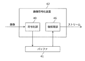
- FIG. 23 is a block diagram of the image coding apparatus according to the present embodiment.
- the image encoding apparatus according to the present embodiment includes an encoding unit 40, a buffer 41, and a post-processing unit 46.
- the post-processing unit 46 includes a coefficient decoding unit 42, a rearrangement unit 43, a tree structure encoding unit 44, and an output unit 45.
- the encoding unit 40 encodes the input image.
- the buffer 41 is a storage unit for holding the encoded stream output from the encoding unit 40.
- the coefficient decoding unit 42 decodes coefficient information in the encoded stream.
- the rearrangement unit 43 rearranges the coefficients in the order of leaf numbers.
- the tree structure encoding unit 44 encodes a tree structure.
- the output unit 45 outputs a stream.
- FIG. 24 is a block diagram of the encoding unit 40 of the present embodiment.
- the encoding unit 40 of the present embodiment includes a control unit 101, a motion detection unit 104, a motion compensation unit 105, an in-plane prediction unit 106, a switch 107, a frequency conversion unit 108, an encoded information calculation unit 109, and a quantization unit 110.
- the frame memory 102 and the buffer 41 may be inside the encoding unit 40 or outside.
- the control unit 101 controls the entire encoding unit 40.
- the frame memory 102 is a storage unit for holding an input image and a locally decoded image.
- the buffer 41 is a storage unit for holding the output encoded stream.
- the motion detection unit 104 performs motion detection.
- the motion compensation unit 105 performs motion compensation according to the motion vector detected by the motion detection unit 104.
- the in-plane prediction unit 106 performs in-plane prediction.
- the switch 107 switches encoding depending on the macroblock type.
- the frequency conversion unit 108 performs frequency conversion.
- the encoding information calculation unit 109 calculates encoding information such as a motion vector and a macroblock type.
- the quantization unit 110 performs quantization.
- the inverse quantization unit 111 performs inverse quantization.
- the inverse frequency transform unit 112 performs inverse frequency transform.
- the reconstruction unit 113 performs image reconstruction from the reference image and the result of the inverse frequency transform.
- the deblock filter unit 114 performs deblock filter processing.
- the variable length coding unit 115 performs variable length coding.
- the encoding unit 40 encodes an input image. Then, the encoding unit 40 writes the encoded stream obtained by encoding into the buffer 41 (S501).
- the encoding of the coefficient information here is the same as that in the first embodiment. Since this is the same as the coding of coefficient information by H.264 / AVC standard CABAC, the description thereof is omitted. Details of the operation of the encoding unit 40 will be described later.
- the coefficient decoding unit 42 reads the encoded stream from the buffer 41 (S502).
- the coefficient decoding unit 42 determines whether the information acquired from the encoded stream is coefficient information (S503).
- the output unit 45 combines the coefficient information and the encoded information and outputs the combined information as an encoded stream (S507).
- the coefficient decoding unit 42 When the information acquired from the encoded stream is coefficient information (Yes in S503), the coefficient decoding unit 42 first decodes the coefficient information (S504). As described above, the encoding of the coefficient information is performed by H.264. Since this is the same as the coding of coefficient information by H.264 / AVC standard CABAC, the description thereof is omitted.
- the rearrangement unit 43 stores the decoded coefficient information in a storage unit such as a memory according to the correspondence between the frequency index and the leaf number (S505). Thereby, the rearrangement unit 43 rearranges the coefficient information in a predetermined order.
- the predetermined order is the order of the leaf numbers, that is, the order of the coefficient information encoded using the tree structure.
- the tree structure encoding unit 44 encodes the coefficients using the tree structure in the order of leaf numbers (S506).
- the encoding by the tree structure is the reverse of the decoding shown in the first embodiment and is also shown in Patent Document 1, so that the description thereof is omitted.
- the output unit 45 combines the encoded information, which is information other than the coefficient information, and the coefficient information, and outputs the result as an encoded stream (S507).
- the control unit 101 determines whether or not the encoding target image is an I (intra) picture (S520).
- the in-plane prediction unit 106 executes an in-plane prediction process (S523).
- the motion detection unit 104 When the encoding target image is not an I picture (No in S520), the motion detection unit 104 performs local decoding of the encoding target macroblock included in the encoding target image and the previously encoded image from the frame memory 102. An image (hereinafter referred to as a reference image) is read out. Then, the motion detection unit 104 executes a motion detection process (S521).
- Motion detection is a process of comparing a coding target image with a reference image and detecting a vector indicating a position having the highest correlation in the reference image, that is, a motion vector.
- a sum of absolute differences SAD, Sum of Absolute Difference
- the calculation used for correlation is not limited to the sum of absolute differences.
- a value obtained by adding a weight related to the generated code amount to the sum of absolute differences may be used.
- a multi-stage search method may be used in which a coarse and wide range is searched and then a fine and narrow range is searched.
- the motion compensation unit 105 executes a motion compensation process using the motion vector output from the motion detection unit 104 (S522). That is, the motion compensation unit 105 reads an image indicated by a motion vector from the frame memory 102 and generates a decimal pixel. When bi-directional reference is used, the motion compensation unit 105 performs weighted addition of two reference images. Then, the motion compensation unit 105 generates a predicted image. Furthermore, the motion compensation unit 105 generates a difference image between the encoding target image and the predicted image.
- the in-plane prediction unit 106 executes in-plane prediction processing (S523). That is, the in-plane prediction unit 106 generates a predicted image from pixels around the encoding target image. Then, the in-plane prediction unit 106 generates a difference image between the encoding target image and the predicted image.
- control unit 101 determines which of the difference image obtained by the motion compensation unit 105 and the difference image obtained by the in-plane prediction unit 106 can reduce the bit amount of the encoded stream. That is, the control unit 101 performs a macroblock type determination process for selecting one of the two predicted images with the switch 107 (S524).
- the selection candidates output from the motion compensation unit 105 and the in-plane prediction unit 106 are not necessarily one by one.
- Each of the motion compensation unit 105 and the in-plane prediction unit 106 may output a plurality of selection candidates.
- the switch 107 is controlled to select the output from the in-plane prediction unit 106 without fail.
- the difference image selected by the switch 107 is input to the frequency conversion unit 108, and the predicted image is input to the reconstruction unit 113.
- the frequency conversion unit 108 performs frequency conversion processing on the difference image obtained according to the determined macroblock type (S525).
- the quantization unit 110 executes a quantization process (S526).
- the inverse quantization unit 111 performs inverse quantization processing (S527).
- the inverse frequency conversion unit 112 performs an inverse frequency conversion process (S528).
- the reconstruction unit 113 executes a reconstruction process for adding the predicted image and the result of the inverse frequency conversion process (S529). Further, the deblocking filter unit 114 performs deblocking filter processing on the image data reconstructed by the reconstruction unit 113 (S530).
- variable length coding unit 115 performs variable length coding on the coefficient information quantized by the quantization unit 110 and the coding information generated by the coding information calculation unit 109.
- the variable length encoding unit 115 writes the encoded stream obtained by variable length encoding into the buffer 41 (S531).
- FIG. 27A is a block diagram showing a characteristic configuration of the image coding apparatus according to Embodiment 5.
- the image encoding device 62 shown in FIG. 27A includes an encoding unit 40 and a post-processing unit 46.
- the buffer 41 exists outside the image encoding device 62. That is, the buffer 41 may not be included in the image encoding device 62.
- FIG. 27B is a flowchart showing a characteristic operation of the image encoding device 62 shown in FIG. 27A.
- the encoding unit 40 generates coefficient data by encoding an image.
- the encoding unit 40 stores the coefficient data in the buffer 41 in a format different from the tree structure (S51).
- the post-processing unit 46 reads the coefficient data from the buffer 41. Then, the post-processing unit 46 encodes the coefficient data using the tree structure (S52). Here, typically, the post-processing unit 46 performs variable-length coding on the coefficient data. Then, the post-processing unit 46 generates an encoded stream including coefficient data encoded using the tree structure.
- the image encoding device 62 encodes the image and generates an encoded stream including coefficient data encoded using a tree structure.
- the buffer 41 preferably has a sufficient storage capacity for holding coefficient data.
- the buffer 41 when the encoding unit 40 encodes an image for each block, the buffer 41 preferably has a storage capacity capable of holding a plurality of blocks.
- the buffer 41 preferably has a storage capacity that is at least twice the size of the coefficient data processed by one frequency conversion or one inverse frequency conversion.
- the buffer 41 may have a storage capacity capable of holding a plurality of blocks compressed by encoding.
- the buffer 41 can accumulate a plurality of coefficient blocks. Therefore, the waiting time for processing is reduced, and the encoding process is executed efficiently.
- the image coding apparatus also does not need to perform coding of coefficient data using a tree structure when coding an image by frequency conversion or the like, as in the first embodiment. . Then, the image coding apparatus performs post-processing of coding of coefficient data using a tree structure. Thereby, the image coding apparatus can suppress a reduction in processing efficiency due to the use of the tree structure.
- the encoding unit 40 can encode an image without using a tree structure. Therefore, the image encoding apparatus according to the present embodiment can encode an image using a tree structure, or can encode an image without using a tree structure.
- the image coding apparatus has been described so as to operate sequentially.
- the image encoding device may execute each process on different data in parallel as long as necessary information is prepared.
- the image encoding apparatus is an encoding unit 40, which is an H.264 standard.
- the coefficient data was encoded by the CABAC encoding method shown in the H.264 / AVC standard.
- the image encoding apparatus may re-encode the coefficient data by the CAVLC method or the encoding method shown in the MPEG2 standard.
- Run-length encoding is an encoding method that encodes coefficient data in a format that combines the number of zero coefficients (ie, runs) and the value of non-zero coefficients (ie, levels).
- data generated by run-length encoding is further encoded by Huffman encoding. If the coefficient data is encoded using runs, the zero coefficient processing cycle is reduced.
- the format of information other than the portion indicating the presence / absence of a coefficient is H.264.
- the format is the same as the H.264 / AVC standard.
- the format of these information may be based on other standards such as MPEG2 or VC-1.
- the format of these information does not need to be based on the existing encoding standard.
- the image coding apparatus changes the coefficient data in the order of leaf numbers when the rearrangement unit 43 writes the data to the memory.
- the image encoding apparatus may change the coefficient data in the order of leaf numbers when the rearrangement unit 43 reads from the memory. In that case, a conversion table from frequency index to leaf number may be used.
- control unit or the like is not described in the post-processing unit 46, but a block, a processor, a program module, or the like that performs timing control or the like may exist in the post-processing unit 46. Further, the control unit 101 of the encoding unit 40 may also have the function.
- the means for realizing the present embodiment may be hardware or software that is operated by a processor.
- the block for storing data may have any configuration such as a memory or a flip-flop.
- the image coding apparatus re-encodes only coefficient information.
- the image encoding apparatus may re-encode coefficient information together with all or part of other information.
- the encoding unit 40 combines coefficient information and other information into one stream.
- the image encoding apparatus may be provided with a plurality of buffers 41 to separately pass coefficient information and other information to the post-processing unit 46.
- the encoding unit 40 performs variable length encoding on the encoded information and the coefficient information.
- the image encoding apparatus may write the encoded information and coefficient information in the buffer 41 as they are.
- the buffer 41 requires a larger capacity, and a larger bandwidth is required for writing and reading the buffer 41.
- the method of the first embodiment is applied to the image coding apparatus.
- the method of the second embodiment, the third embodiment, or the fourth embodiment may be applied to the image coding apparatus.
- the rearrangement process may be executed by the encoding unit 40 as in the second embodiment.
- the binarization process and the arithmetic coding process may be executed by the post-processing unit 46.
- the encoding process flow shown in the present embodiment shows an example, and the encoding process procedure is not limited to the encoding process flow shown in the present embodiment.
- another processing unit may execute a process executed by a specific processing unit.
- the order in which the processes are executed may be changed, or a plurality of processes may be executed in parallel.
- the present invention can be realized not only as an image decoding device or an image encoding device, but also as a method having steps as processing units constituting the image decoding device or the image encoding device. For example, these steps are performed by a computer.
- the present invention can be realized as a program for causing a computer to execute the steps included in these methods.
- the present invention can be realized as a computer-readable recording medium such as a CD-ROM in which the program is recorded.
- a plurality of components included in the image decoding device or the image encoding device may be realized as an LSI (Large Scale Integration) that is an integrated circuit. These components may be individually made into one chip, or may be made into one chip so as to include a part or all of them. For example, the components other than the memory may be integrated into one chip.
- LSI Large Scale Integration
- IC Integrated Circuit
- system LSI system LSI
- super LSI super LSI
- ultra LSI ultra LSI depending on the degree of integration.
- the method of circuit integration is not limited to LSI, and implementation with a dedicated circuit or a general-purpose processor is also possible.
- An FPGA Field Programmable Gate Array
- a reconfigurable processor that can reconfigure the connection and setting of circuit cells inside the LSI may be used.
- the storage medium may be any medium that can record a program, such as a magnetic disk, an optical disk, a magneto-optical disk, an IC card, and a semiconductor memory.
- FIG. 28 is a diagram showing an overall configuration of a content supply system ex100 that realizes a content distribution service.
- the communication service providing area is divided into desired sizes, and base stations ex106 to ex110, which are fixed radio stations, are installed in each cell.
- devices such as a computer ex111, a PDA (Personal Digital Assistant) ex112, a camera ex113, a mobile phone ex114, and a game machine ex115 are mutually connected via a telephone network ex104 and base stations ex106 to ex110. Connected. Each device is connected to the Internet ex101 via the Internet service provider ex102.
- PDA Personal Digital Assistant
- each device may be directly connected to the telephone network ex104 without going through the base stations ex106 to ex110 which are fixed wireless stations.
- the devices may be directly connected to each other via short-range wireless or the like.
- the camera ex113 is a device that can shoot a moving image such as a digital video camera
- the camera ex116 is a device that can shoot a still image and a moving image such as a digital camera.
- the mobile phone ex114 is a GSM (Global System for Mobile Communications) method, a CDMA (Code Division Multiple Access) method, a W-CDMA (Wideband-Code Division MultipleL), or a high access rate (L) system. (High Speed Packet Access) type mobile phone, PHS (Personal Handyphone System), etc., which may be either.
- the camera ex113 and the like are connected to the streaming server ex103 through the base station ex109 and the telephone network ex104, thereby enabling live distribution and the like.
- live distribution the content (for example, music live video) captured by the user using the camera ex113 is encoded as described in the above embodiments and transmitted to the streaming server ex103.
- the streaming server ex103 streams the transmitted content data to the requested client.
- the client include a computer ex111, a PDA ex112, a camera ex113, a mobile phone ex114, a game machine ex115, and the like that can decode the encoded data. Each device that has received the distributed data decodes and reproduces the received data.
- the encoded processing of the captured data may be performed by the camera ex113, the streaming server ex103 that performs data transmission processing, or may be performed in a shared manner.
- the distributed processing of the distributed data may be performed by the client, the streaming server ex103, or may be performed in a shared manner.
- still images and / or moving image data captured by the camera ex116 may be transmitted to the streaming server ex103 via the computer ex111.
- the encoding process in this case may be performed by any of the camera ex116, the computer ex111, and the streaming server ex103, or may be performed in a shared manner.
- these encoding processing and decoding processing are generally executed in a computer ex111 and an LSI (Large Scale Integration) ex500 included in each device.
- the LSI ex500 may be configured as a single chip or a plurality of chips.
- image encoding software or image decoding software is incorporated into any recording medium (CD-ROM, flexible disk, hard disk, etc.) that can be read by the computer ex111 and the like, and encoding processing or decoding processing is performed using the software. May be performed.
- moving image data acquired by the camera may be transmitted. The moving image data at this time is data encoded by the LSI ex500 included in the mobile phone ex114.
- the streaming server ex103 may be a plurality of servers or a plurality of computers, and may process, record, and distribute data in a distributed manner.
- the encoded data can be received and reproduced by the client.
- the information transmitted by the user can be received, decrypted and reproduced in real time by the client, and even a user who does not have special rights and facilities can realize personal broadcasting.
- At least one of the image encoding device and the image decoding device according to each of the above embodiments can be incorporated in the digital broadcasting system ex200.
- a bit stream of video information is transmitted to a communication or satellite ex202 via radio waves.
- This bit stream is an encoded bit stream encoded by the image encoding method described in the above embodiments.
- the broadcasting satellite ex202 transmits a radio wave for broadcasting, and the home antenna ex204 capable of receiving the satellite broadcast receives the radio wave.
- the received bit stream is decoded and reproduced by a device such as the television (receiver) ex300 or the set top box (STB) ex217.
- the image decoding apparatus described in the above embodiment can be mounted on the playback apparatus ex212 that reads and decodes the bitstream recorded on the recording medium ex214 such as a CD and a DVD that are recording media.
- the reproduced video signal is displayed on the monitor ex213.
- the image decoding shown in the above embodiments is also performed on the reader / recorder ex218 that reads and decodes the encoded bitstream recorded on the recording medium ex215 such as DVD and BD, or encodes and writes the video signal on the recording medium ex215.
- the reproduced video signal is displayed on the monitor ex219, and the video signal can be reproduced in another device and system by the recording medium ex215 in which the encoded bitstream is recorded.
- an image decoding device may be mounted in a set-top box ex217 connected to a cable ex203 for cable television or an antenna ex204 for satellite / terrestrial broadcasting and displayed on the monitor ex219 of the television. At this time, the image decoding apparatus may be incorporated in the television instead of the set top box.
- FIG. 30 is a diagram illustrating a television (receiver) ex300 that uses the image decoding method described in each of the above embodiments.
- the television ex300 includes a tuner ex301 that acquires or outputs a bit stream of video information via the antenna ex204 or the cable ex203 that receives the broadcast, and the encoded data that is demodulated or transmitted to the outside.
- a modulation / demodulation unit ex302 that modulates and a multiplexing / separation unit ex303 that separates demodulated video data and audio data or multiplexes encoded video data and audio data.
- the television ex300 decodes each of the audio data and the video data, or encodes each information, an audio signal processing unit ex304, a signal processing unit ex306 including the video signal processing unit ex305, and outputs the decoded audio signal.
- the television ex300 includes an interface unit ex317 including an operation input unit ex312 that receives an input of a user operation.
- the television ex300 includes a control unit ex310 that controls each unit in an integrated manner, and a power supply circuit unit ex311 that supplies power to each unit.
- the interface unit ex317 includes a bridge ex313 connected to an external device such as a reader / recorder ex218, a recording unit ex216 such as an SD card, and an external recording such as a hard disk.
- a driver ex315 for connecting to a medium, a modem ex316 for connecting to a telephone network, and the like may be included.
- the recording medium ex216 can record information electrically by using a nonvolatile / volatile semiconductor memory element to be stored.
- Each part of the television ex300 is connected to each other via a synchronous bus.
- the television ex300 receives a user operation from the remote controller ex220 or the like, and demultiplexes the video data and audio data demodulated by the modulation / demodulation unit ex302 by the multiplexing / separation unit ex303 based on the control of the control unit ex310 having a CPU or the like. . Furthermore, the television ex300 decodes the separated audio data by the audio signal processing unit ex304, and the separated video data is decoded by the video signal processing unit ex305 using the decoding method described in the above embodiments. The decoded audio signal and video signal are output to the outside from the output unit ex309.
- these signals may be temporarily stored in the buffers ex318, ex319, etc. so that the audio signal and the video signal are reproduced in synchronization.
- the television ex300 may read the encoded bitstream encoded from the recording media ex215 and ex216 such as a magnetic / optical disk and an SD card, not from a broadcast or the like.
- the television ex300 encodes an audio signal and a video signal and transmits them to the outside or writes them on a recording medium or the like.
- the television ex300 receives a user operation from the remote controller ex220 or the like, and encodes an audio signal with the audio signal processing unit ex304 based on the control of the control unit ex310, and converts the video signal with the video signal processing unit ex305.
- Encoding is performed using the encoding method described in (1).
- the encoded audio signal and video signal are multiplexed by the multiplexing / demultiplexing unit ex303 and output to the outside. When multiplexing, these signals may be temporarily stored in the buffers ex320 and ex321 so that the audio signal and the video signal are synchronized.
- buffers ex318 to ex321 may be provided as shown in the figure, or one or more buffers may be shared. Further, in addition to the illustrated example, data may be stored in the buffer as a buffer material that prevents system overflow and underflow, for example, between the modulation / demodulation unit ex302 and the multiplexing / demultiplexing unit ex303.
- the television ex300 In addition to acquiring audio data and video data from broadcast and recording media, the television ex300 has a configuration for receiving AV input of a microphone and a camera, and even if encoding processing is performed on the data acquired therefrom Good.
- the television ex300 has been described as a configuration capable of the above-described encoding processing, multiplexing, and external output. However, these processing cannot be performed, and only the above-described reception, decoding processing, and external output are possible. It may be.
- the decoding process or the encoding process may be performed by either the television ex300 or the reader / recorder ex218,
- the ex300 and the reader / recorder ex218 may share each other.
- FIG. 31 shows a configuration of the information reproducing / recording unit ex400 when data is read from or written to an optical disk.
- the information reproducing / recording unit ex400 includes elements ex401 to ex407 described below.
- the optical head ex401 writes information by irradiating a laser spot onto the recording surface of the recording medium ex215 that is an optical disc, and reads information by detecting reflected light from the recording surface of the recording medium ex215.
- the modulation recording unit ex402 electrically drives a semiconductor laser built in the optical head ex401 and modulates the laser beam according to the recording data.
- the reproduction demodulator ex403 amplifies a reproduction signal obtained by electrically detecting reflected light from the recording surface by a photodetector built in the optical head ex401, separates and demodulates a signal component recorded on the recording medium ex215, and is necessary. To play back information.
- the buffer ex404 temporarily holds information to be recorded on the recording medium ex215 and information reproduced from the recording medium ex215.
- the disk motor ex405 rotates the recording medium ex215.
- the servo control unit ex406 moves the optical head ex401 to a predetermined information track while controlling the rotational drive of the disk motor ex405, and performs a laser
- the system control unit ex407 controls the entire information reproduction / recording unit ex400.
- the system control unit ex407 uses various types of information held in the buffer ex404, and generates and adds new information as necessary, as well as the modulation recording unit ex402, the reproduction demodulation unit This is realized by recording / reproducing information through the optical head ex401 while operating the ex403 and the servo control unit ex406 in a coordinated manner.
- the system control unit ex407 includes, for example, a microprocessor, and executes these processes by executing a read / write program.
- the optical head ex401 has been described as irradiating a laser spot, but it may be configured to perform higher-density recording using near-field light.
- FIG. 32 shows a schematic diagram of a recording medium ex215 that is an optical disk.
- Guide grooves grooves
- address information indicating the absolute position on the disc is recorded in advance on the information track ex230 by changing the shape of the groove.
- This address information includes information for specifying the position of the recording block ex231 which is a unit for recording data, and the recording block is specified by reproducing the information track ex230 and reading the address information in a recording and reproducing apparatus.
- the recording medium ex215 includes a data recording area ex233, an inner peripheral area ex232, and an outer peripheral area ex234.
- the area used for recording the user data is the data recording area ex233, and the inner circumference area ex232 and the outer circumference area ex234 arranged on the inner circumference or outer circumference of the data recording area ex233 are used for specific purposes other than user data recording. Used.
- the information reproducing / recording unit ex400 reads / writes encoded audio data, video data, or encoded data obtained by multiplexing these data with respect to the data recording area ex233 of the recording medium ex215.
- an optical disk such as a single-layer DVD or BD has been described as an example.
- the present invention is not limited to these, and an optical disk having a multilayer structure and capable of recording other than the surface may be used. It also has a structure that performs multidimensional recording / reproduction, such as recording information using light of various different wavelengths at the same location on the disc, and recording different layers of information from various angles. It may be an optical disk.
- the car ex210 having the antenna ex205 can receive data from the satellite ex202 and the like, and the moving image can be reproduced on a display device such as the car navigation ex211 that the car ex210 has.
- the configuration of the car navigation ex211 is, for example, the configuration shown in FIG. 30 to which a GPS receiver is added, and the same can be considered for the computer ex111 and the mobile phone ex114.
- the mobile phone ex114 and the like can be used in three ways: a transmitting terminal having only an encoder and a receiving terminal having only a decoder. The implementation form of can be considered.
- the image encoding method or the image decoding method shown in each of the above embodiments can be used in any of the above-described devices or systems, and by doing so, the effects described in the above embodiments can be obtained. Can be obtained.
- the image decoding apparatus shown in the first embodiment is realized as an LSI that is typically a semiconductor integrated circuit.
- the realized form is shown in FIG.
- the buffer 4 and the frame memory 12 are realized on the DRAM, and other circuits and memories are configured on the LSI.
- LSI LSI
- IC system LSI
- super LSI ultra LSI depending on the degree of integration
- the method of circuit integration is not limited to LSI, and implementation with a dedicated circuit or a general-purpose processor is also possible.
- An FPGA Field Programmable Gate Array
- a reconfigurable processor that can reconfigure the connection and setting of circuit cells inside the LSI may be used.
- a drawing device corresponding to various uses can be configured.
- the present invention can be used as information drawing means in cellular phones, televisions, digital video recorders, digital video cameras, car navigation systems, and the like.
- a display in addition to a cathode ray tube (CRT), a flat display such as a liquid crystal, a PDP (plasma display panel) and an organic EL, a projection display represented by a projector, and the like can be combined.
- the LSI in the present embodiment cooperates with a DRAM (Dynamic Random Access Memory) including a bit stream buffer for storing an encoded stream and a frame memory for storing an image, thereby performing an encoding process or a decoding process. May be performed.
- the LSI in the present embodiment may be linked with other storage devices such as eDRAM (embedded DRAM), SRAM (Static Random Access Memory), or hard disk instead of DRAM.
- FIG. 34 shows a configuration of an LSI ex500 that is made into one chip.
- the LSI ex500 includes elements ex502 to ex509 described below, and each element is connected via a bus ex510.
- the power supply circuit unit ex505 starts up to an operable state by supplying power to each unit when the power supply is in an on state.
- the LSI ex500 when performing the encoding process, receives an AV signal input from the microphone ex117, the camera ex113, and the like by the AV I / Oex 509.
- the input AV signal is temporarily stored in an external memory ex511 such as SDRAM.
- the accumulated data is divided into a plurality of times as appropriate according to the processing amount and processing speed, and sent to the signal processing unit ex507.
- the signal processing unit ex507 performs encoding of an audio signal and / or encoding of a video signal.
- the encoding process of the video signal is the encoding process described in the above embodiment.
- the signal processing unit ex507 further performs processing such as multiplexing the encoded audio data and the encoded video data according to circumstances, and outputs the result from the stream I / Oex 504 to the outside.
- the output bit stream is transmitted to the base station ex107 or written to the recording medium ex215.
- the LSI ex500 transmits the encoded data obtained from the base station ex107 by the stream I / Oex 504 or the recording medium ex215 based on the control of the microcomputer (microcomputer) ex502.
- the encoded data obtained by reading is temporarily stored in the memory ex511 or the like.
- the accumulated data is appropriately divided into a plurality of times according to the processing amount and the processing speed and sent to the signal processing unit ex507, where the signal processing unit ex507 decodes the audio data and / or the video data. Decryption is performed.
- the decoding process of the video signal is the decoding process described in the above embodiments.
- each signal may be temporarily stored in the memory ex511 or the like so that the decoded audio signal and the decoded video signal can be reproduced in synchronization.
- the decoded output signal is output from the AVI / Oex 509 to the monitor ex219 or the like through the memory ex511 or the like as appropriate.
- the memory controller ex503 is used.
- the memory ex511 has been described as an external configuration of the LSI ex500. However, a configuration included in the LSI ex500 may be used.
- the LSI ex500 may be made into one chip or a plurality of chips.
- LSI LSI
- IC system LSI
- super LSI ultra LSI depending on the degree of integration
- the method of circuit integration is not limited to LSI, and implementation with a dedicated circuit or a general-purpose processor is also possible.
- An FPGA Field Programmable Gate Array
- a reconfigurable processor that can reconfigure the connection and setting of circuit cells inside the LSI may be used.
- the image decoding apparatus and the image encoding apparatus according to the present invention can be used for various purposes.
- it can be used for high-resolution information display devices such as televisions, digital video recorders, car navigation systems, mobile phones, digital cameras, and digital video cameras, or imaging devices, and has high utility value.
- Tree structure decoding unit 2 29, 43 Rearrangement unit 3, 28 Coefficient encoding unit 4, 41, ex318, ex319, ex320, ex321, ex404 Buffer 5, 27 Decoding unit 6, 26, 34, 37 Preprocessing unit 11 , 101, ex310 Control unit 12, 102 Frame memory 13 Variable length decoding unit 14, 111 Inverse quantization unit 15, 112 Inverse frequency conversion unit 16, 106 In-plane prediction unit 17 Motion vector calculation unit 18, 105 Motion compensation unit 19, 107 Switch 20, 113 Reconfiguration unit 21, 114 Deblock filter unit 30 Arithmetic decoding unit 31 Inverse binarization unit 32 Re-encoding unit 33, 36 Storage unit 35 Binarization unit 40 Encoding unit 42 Coefficient decoding unit 44 Tree Structure encoding unit 45, ex309 output unit 46 Post-processing unit 61 Image decoding device 62 Image code Device 104 motion detection unit 108 frequency conversion unit 109 encoding information calculation unit 110 quantization unit 115 variable length encoding unit ex100 content supply system ex101 internet ex102 internet service provider ex103 streaming server ex104 telephone network ex
Landscapes
- Engineering & Computer Science (AREA)
- Multimedia (AREA)
- Signal Processing (AREA)
- Compression Or Coding Systems Of Tv Signals (AREA)
Abstract
L'invention concerne un appareil de décodage d'image capable de supprimer la dégradation de l'efficacité du traitement provoquée par l'utilisation d'une structure en arborescence. Dans un mode de réalisation de l'invention, l'appareil de décodage d'image peut être utilisé pour décoder une image à partir d'un flux codé contenant des données de coefficient codées en utilisant une structure en arborescence et comprend : une unité de prétraitement (6) pour décoder les données de coefficient codées en utilisant la structure en arborescence et pour stocker, dans une mémoire tampon (4), les données de coefficient décodées dans un format différent de la structure en arborescence ; et une unité de décodage (5) pour lire, depuis la mémoire tampon (4), les données de coefficient afin de décoder l'image.
Applications Claiming Priority (2)
| Application Number | Priority Date | Filing Date | Title |
|---|---|---|---|
| JP2010092014 | 2010-04-13 | ||
| JP2010-092014 | 2010-04-13 |
Publications (1)
| Publication Number | Publication Date |
|---|---|
| WO2011129052A1 true WO2011129052A1 (fr) | 2011-10-20 |
Family
ID=44798442
Family Applications (1)
| Application Number | Title | Priority Date | Filing Date |
|---|---|---|---|
| PCT/JP2011/001439 Ceased WO2011129052A1 (fr) | 2010-04-13 | 2011-03-11 | Appareil de décodage d'image, appareil de codage d'image, procédé de décodage d'image et procédé de codage d'image |
Country Status (1)
| Country | Link |
|---|---|
| WO (1) | WO2011129052A1 (fr) |
Cited By (2)
| Publication number | Priority date | Publication date | Assignee | Title |
|---|---|---|---|---|
| JP2014006900A (ja) * | 2012-06-22 | 2014-01-16 | Palo Alto Research Center Inc | 圧縮水平順序付けエッジシーケンス符号化のためのシステム及び方法 |
| CN115103140A (zh) * | 2022-06-21 | 2022-09-23 | 利亚德光电股份有限公司 | 数据处理方法、处理芯片、模组控制板及视频处理设备 |
Citations (4)
| Publication number | Priority date | Publication date | Assignee | Title |
|---|---|---|---|---|
| US20040085233A1 (en) * | 2002-10-30 | 2004-05-06 | Lsi Logic Corporation | Context based adaptive binary arithmetic codec architecture for high quality video compression and decompression |
| JP2008523644A (ja) * | 2004-11-09 | 2008-07-03 | 松下電器産業株式会社 | 復号処理装置および復号処理方法 |
| JP2008530829A (ja) * | 2004-12-22 | 2008-08-07 | 株式会社エヌ・ティ・ティ・ドコモ | 係数の位置をコード化する方法及び装置 |
| JP2008289105A (ja) * | 2007-05-21 | 2008-11-27 | Sanyo Electric Co Ltd | 画像処理装置およびそれを搭載した撮像装置 |
-
2011
- 2011-03-11 WO PCT/JP2011/001439 patent/WO2011129052A1/fr not_active Ceased
Patent Citations (4)
| Publication number | Priority date | Publication date | Assignee | Title |
|---|---|---|---|---|
| US20040085233A1 (en) * | 2002-10-30 | 2004-05-06 | Lsi Logic Corporation | Context based adaptive binary arithmetic codec architecture for high quality video compression and decompression |
| JP2008523644A (ja) * | 2004-11-09 | 2008-07-03 | 松下電器産業株式会社 | 復号処理装置および復号処理方法 |
| JP2008530829A (ja) * | 2004-12-22 | 2008-08-07 | 株式会社エヌ・ティ・ティ・ドコモ | 係数の位置をコード化する方法及び装置 |
| JP2008289105A (ja) * | 2007-05-21 | 2008-11-27 | Sanyo Electric Co Ltd | 画像処理装置およびそれを搭載した撮像装置 |
Cited By (3)
| Publication number | Priority date | Publication date | Assignee | Title |
|---|---|---|---|---|
| JP2014006900A (ja) * | 2012-06-22 | 2014-01-16 | Palo Alto Research Center Inc | 圧縮水平順序付けエッジシーケンス符号化のためのシステム及び方法 |
| US9876638B2 (en) | 2012-06-22 | 2018-01-23 | Palo Alto Research Center Incorporated | System and method for compressed level-ordered edge sequence encoding |
| CN115103140A (zh) * | 2022-06-21 | 2022-09-23 | 利亚德光电股份有限公司 | 数据处理方法、处理芯片、模组控制板及视频处理设备 |
Similar Documents
| Publication | Publication Date | Title |
|---|---|---|
| US8718149B2 (en) | Image coding method and image decoding method | |
| CN102550030B (zh) | 图像解码装置、图像编码装置、及其方法、程序、集成电路以及代码转换装置 | |
| JP5518069B2 (ja) | 画像復号装置、画像符号化装置、画像復号方法、画像符号化方法、プログラムおよび集積回路 | |
| JP6390883B2 (ja) | 画像処理装置 | |
| JP5659160B2 (ja) | 動画像復号装置、動画像符号化装置、動画像復号回路及び動画像復号方法 | |
| JPWO2012046435A1 (ja) | 画像処理装置、画像符号化方法および画像処理方法 | |
| WO2010150486A1 (fr) | Procédé de codage vidéo et dispositif de codage vidéo | |
| CN102246525A (zh) | 运动图像编码方法、运动图像解码方法、运动图像编码装置、运动图像解码装置、程序、及集成电路 | |
| WO2011161949A1 (fr) | Appareil de décodage d'image, procédé de décodage d'image, circuit intégré et programme | |
| JP5999515B2 (ja) | 画像処理装置、及び、画像処理方法 | |
| JP5546044B2 (ja) | 画像復号装置、画像符号化装置、画像復号回路及び画像復号方法 | |
| WO2010131422A1 (fr) | Appareil de décodage d'image, circuit intégré, procédé de décodage d'image et système de décodage d'image | |
| WO2011129052A1 (fr) | Appareil de décodage d'image, appareil de codage d'image, procédé de décodage d'image et procédé de codage d'image | |
| WO2013076897A1 (fr) | Dispositif de traitement d'image et procédé de traitement d'image | |
| JP2011182132A (ja) | 画像符号化装置、画像復号装置、画像符号化方法、画像復号方法、集積回路およびプログラム |
Legal Events
| Date | Code | Title | Description |
|---|---|---|---|
| 121 | Ep: the epo has been informed by wipo that ep was designated in this application |
Ref document number: 11768579 Country of ref document: EP Kind code of ref document: A1 |
|
| NENP | Non-entry into the national phase |
Ref country code: DE |
|
| 122 | Ep: pct application non-entry in european phase |
Ref document number: 11768579 Country of ref document: EP Kind code of ref document: A1 |
|
| NENP | Non-entry into the national phase |
Ref country code: JP |