WO2011129403A1 - Système de communications hertziennes, appareil de communications hertziennes, programme et procédé d'émission - Google Patents
Système de communications hertziennes, appareil de communications hertziennes, programme et procédé d'émission Download PDFInfo
- Publication number
- WO2011129403A1 WO2011129403A1 PCT/JP2011/059286 JP2011059286W WO2011129403A1 WO 2011129403 A1 WO2011129403 A1 WO 2011129403A1 JP 2011059286 W JP2011059286 W JP 2011059286W WO 2011129403 A1 WO2011129403 A1 WO 2011129403A1
- Authority
- WO
- WIPO (PCT)
- Prior art keywords
- transmission
- wireless communication
- frequency
- antennas
- allocation
- Prior art date
- Legal status (The legal status is an assumption and is not a legal conclusion. Google has not performed a legal analysis and makes no representation as to the accuracy of the status listed.)
- Ceased
Links
Images





Classifications
-
- H—ELECTRICITY
- H04—ELECTRIC COMMUNICATION TECHNIQUE
- H04B—TRANSMISSION
- H04B7/00—Radio transmission systems, i.e. using radiation field
- H04B7/02—Diversity systems; Multi-antenna system, i.e. transmission or reception using multiple antennas
- H04B7/04—Diversity systems; Multi-antenna system, i.e. transmission or reception using multiple antennas using two or more spaced independent antennas
- H04B7/0413—MIMO systems
- H04B7/0456—Selection of precoding matrices or codebooks, e.g. using matrices antenna weighting
- H04B7/0486—Selection of precoding matrices or codebooks, e.g. using matrices antenna weighting taking channel rank into account
-
- H—ELECTRICITY
- H04—ELECTRIC COMMUNICATION TECHNIQUE
- H04B—TRANSMISSION
- H04B7/00—Radio transmission systems, i.e. using radiation field
- H04B7/02—Diversity systems; Multi-antenna system, i.e. transmission or reception using multiple antennas
- H04B7/04—Diversity systems; Multi-antenna system, i.e. transmission or reception using multiple antennas using two or more spaced independent antennas
- H04B7/06—Diversity systems; Multi-antenna system, i.e. transmission or reception using multiple antennas using two or more spaced independent antennas at the transmitting station
- H04B7/0613—Diversity systems; Multi-antenna system, i.e. transmission or reception using multiple antennas using two or more spaced independent antennas at the transmitting station using simultaneous transmission
- H04B7/0667—Diversity systems; Multi-antenna system, i.e. transmission or reception using multiple antennas using two or more spaced independent antennas at the transmitting station using simultaneous transmission of delayed versions of same signal
- H04B7/0669—Diversity systems; Multi-antenna system, i.e. transmission or reception using multiple antennas using two or more spaced independent antennas at the transmitting station using simultaneous transmission of delayed versions of same signal using different channel coding between antennas
-
- H—ELECTRICITY
- H04—ELECTRIC COMMUNICATION TECHNIQUE
- H04L—TRANSMISSION OF DIGITAL INFORMATION, e.g. TELEGRAPHIC COMMUNICATION
- H04L25/00—Baseband systems
- H04L25/02—Details ; arrangements for supplying electrical power along data transmission lines
- H04L25/03—Shaping networks in transmitter or receiver, e.g. adaptive shaping networks
- H04L25/03891—Spatial equalizers
-
- H—ELECTRICITY
- H04—ELECTRIC COMMUNICATION TECHNIQUE
- H04L—TRANSMISSION OF DIGITAL INFORMATION, e.g. TELEGRAPHIC COMMUNICATION
- H04L5/00—Arrangements affording multiple use of the transmission path
- H04L5/0001—Arrangements for dividing the transmission path
- H04L5/0014—Three-dimensional division
- H04L5/0023—Time-frequency-space
-
- H—ELECTRICITY
- H04—ELECTRIC COMMUNICATION TECHNIQUE
- H04L—TRANSMISSION OF DIGITAL INFORMATION, e.g. TELEGRAPHIC COMMUNICATION
- H04L5/00—Arrangements affording multiple use of the transmission path
- H04L5/003—Arrangements for allocating sub-channels of the transmission path
- H04L5/0048—Allocation of pilot signals, i.e. of signals known to the receiver
Definitions
- the present invention relates to a wireless communication system, a wireless communication apparatus, a program, and a transmission method.
- This application claims priority based on Japanese Patent Application No. 2010-094037 filed in Japan on April 15, 2010, the contents of which are incorporated herein by reference.
- LTE Long Term Evolution
- LTE-A Long Term Evolution-Advanced
- MIMO Multiple Input Multiple Output
- the cost and scale of the terminal are important.
- multicarrier transmission such as OFDM is not suitable for uplink transmission because the transmission signal has a high PAPR (Peak to Average Power Ratio) and requires a power amplifier with a wide linear region. That is, in order to maintain wide coverage in the uplink, single carrier transmission with a low PAPR is desirable, and in the uplink of LTE, SC-FDMA (Single-Carrier-Frequency-Division-Multiple-Access; Single Carrier Frequency Division Multiple Access, DFT-S-OFDM) Also called).
- Clustered has a problem that PAPR deteriorates compared with SC-FDMA.
- the users near the base station can satisfy the reception quality at the base station with low output, the linearity of the amplifier of the mobile terminal does not matter much. Therefore, users close to the base station use Clustered DFT-S-OFDM, and users far from the base station perform transmission using SC-FDMA, so that high system throughput can be achieved while maintaining coverage. .
- each data can be separated by applying spatial filtering such as MMSE (Minimum Mean Square Error), MLD (Maximum LikelihoodDetection) or the like at the receiver. Further, by using MIMO transmission and Clustered together, frequency utilization efficiency can be improved.
- MMSE Minimum Mean Square Error
- MLD Maximum LikelihoodDetection
- Patent Document 1 discloses that transmission with higher frequency utilization efficiency is possible by allowing different frequency assignments for each antenna.
- Patent Document 1 if transmission diversity is applied to Patent Document 1 as it is, that is, if the same data is transmitted with different frequency assignments, there is a problem that interference between transmission antennas occurs and transmission efficiency decreases.
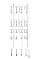
- FIG. 17 when the same data is transmitted from the transmission antenna # 0 and the transmission antenna # 1 with different frequency assignments, the same frequency spectrum is transmitted from the transmission antenna # 0 and the transmission antenna # 1 in the frequency index 3. Therefore, a receiver that is a base station can receive without interference between antennas.
- the mutual frequency spectra become interference.
- MMSE filtering and MLD different frequency spectra can be separated by receiving processing such as MMSE filtering and MLD in the receiver. It is also conceivable to combine the spectrum transmitted at different frequencies after the frequency spectrum separation. However, MMSE and MLD have a problem that transmission characteristics deteriorate because interference remains.
- the present invention has been made in view of such circumstances, and an object thereof is to provide a wireless communication system, a wireless communication apparatus, a program, and a transmission method capable of suppressing interference between transmission antennas and performing good transmission. There is to do.
- the present invention has been made to solve the above-described problems, and a wireless communication system according to the present invention includes a first wireless communication apparatus having a plurality of transmission antennas and transmitting a signal using a MIMO scheme; A wireless communication system having a second wireless communication device for receiving the signal, wherein the first wireless communication device transmits the same data when transmitting with a rank smaller than the number of transmission antennas.
- the antennas have the same frequency allocation.
- wireless communications system of this invention is the above-mentioned radio
- the said allocation information generation part determines the same number of frequency allocations as a rank number, It is characterized by the above-mentioned.
- wireless communications system of this invention is the above-mentioned radio
- the wireless communication apparatus of the present invention is a wireless communication apparatus that has a plurality of transmission antennas and transmits signals in the MIMO scheme, and transmits the same data when transmitting with a rank smaller than the number of transmission antennas.
- the transmission antennas that transmit are assigned the same frequency.
- a wireless communication apparatus is a wireless communication apparatus that has a plurality of transmission antennas and receives a signal from another wireless communication apparatus that transmits a signal using a MIMO scheme.
- the transmission apparatus includes an allocation information generation unit that determines frequency allocation so that transmission antennas that transmit the same data have the same frequency allocation.
- a program of a wireless communication apparatus that has a plurality of transmission antennas and receives a signal from another wireless communication apparatus that transmits a signal using the MIMO scheme.
- the transmission antennas that transmit the same data are caused to function as an allocation information generation unit that determines frequency allocation so that the same frequency allocation is performed.
- the transmission method of the present invention includes a first wireless communication apparatus that has a plurality of transmission antennas and transmits a signal using the MIMO scheme, and a second wireless communication apparatus that receives the signal.
- the transmission method in the communication system when the first wireless communication apparatus transmits with a rank smaller than the number of transmission antennas, the transmission antennas to which the same data is transmitted have the same frequency allocation.
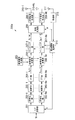
- the IDFT units 106-1 to 106-R perform inverse discrete Fourier transform on the input signals to convert them into time domain signals.
- Each of the obtained time domain signals corresponding to each layer is input to the corresponding demodulating units 107-1 to 107-R.
- Demodulating sections 107-1 to 107-R demodulate the time domain signal and convert it into bits.
- Decoding sections 108-1 to 108-R apply bit error correction decoding to the bits obtained by demodulation sections 107-1 to 107-R, respectively, to obtain bit sequences.
- P / S conversion section 109 performs parallel-serial conversion on the bit series obtained by decoding sections 108-1 to 108-R to obtain reception bit series RB.
- the allocation information generation unit 112 may determine the allocation of each transmission antenna using the SNR calculated from the channel estimation value estimated by the channel estimation unit 110 in FIG. 4 as an allocation criterion, as shown in FIG.
- the SINR Signal-to-Interference plus Noise power Ratio
- Assignment may be determined.
- the signal vector D 1 and D 2 are sent, even the same frequency assignment as the transmission antenna # 0 and the transmission antenna # 1, the receiving since the transmission signal is different from the side Signal separation processing must be performed. Therefore, in transmission antenna # 2 and transmission antenna # 3, it is only necessary to assign a frequency (spectrum) so that reception quality is the best regardless of assignment of transmission antenna # 0 and transmission antenna # 1.
- the allocation may be determined in consideration of signal separation processing at the equalization unit 105 on the reception side. For example, when performing MMSE filtering, allocation may be performed so that the SINR after MMSE is maximized, or when the equalizer 105 includes an interference canceller or the like, allocation may be performed so that SNR is maximized. Good.
- the allocation information generation unit 112 uses the following equation (7) as the precoding matrix w.
- the allocation information generating unit 112 determines frequency allocation for each layer so that transmission is performed. Further, as shown in equation (7), from the transmission antenna # 2 and the transmission antenna # 3, the signal vector D 1 is transmitted, the allocation information generation unit 112 determines the frequency allocation for each layer Transmission antenna # 2 and transmission antenna # 3 perform transmission using the same frequency. Different allocations are used for the frequency allocation of the transmission antenna # 0 and the transmission antenna # 0, that is, the frequency allocation of the first layer, and the frequency allocation of the transmission antenna # 2 and the transmission antenna # 3, that is, the frequency allocation of the second layer. be able to. As another example, the following equation (8) may be used as the precoding matrix w.
- the frequency index signals 2, 4, 6, 7, 10, 11 and the first to sixth frequency domain signals (D 0 ( 0) to D 0 (5)) are assigned in order.
- the same signal vector D 0 from all transmission antenna # 3 is transmitted from the transmission antenna # 0.
- the mobile station apparatus 200a can perform transmission so as not to cause inter-antenna interference on the reception side.
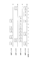
- FIG. 10 is a diagram illustrating an example of frequency allocation when the number of transmission antennas Nt is 4 and the rank R is 3.
- signals of the same data are transmitted from transmission antenna # 0 and transmission antenna # 2.
- the frequency allocation of the transmission antenna # 0 and the transmission antenna # 2 is the same. Since the frequency allocation is the same, the numbers of DFT points of the DFT units in the transmission antenna # 0 and the transmission antenna # 2 in FIG. 2 are the same. However, it is not necessary for the transmission antenna # 1 and the transmission antenna # 3 to have the same frequency allocation for the transmission antenna # 0 and the transmission antenna # 2, and the number of frequency points to be used may be different.
- rank R is 2 and 1, detailed description is omitted, but the number of frequency points used is the same for transmitting antennas that transmit the same data, but the frequency that is used for antennas transmitting different data is the same. The points may be different.
- the frequency assignment of each transmission antenna is made the same according to the number of ranks. Specifically, when the precoding matrix is decomposed into column vectors, the frequency allocation is made the same for the transmission antenna having a non-zero value for a layer having a plurality of non-zero values.
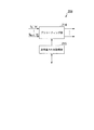
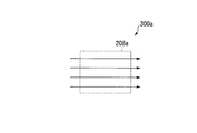
- the configurations of the mobile station devices 300a to 300d in the present embodiment are substantially the same as the configuration of the mobile station device 200a in the first embodiment. However, instead of the transmission processing unit 208, any one of the transmission processing units 208a to 208d is provided, and the processing applied to the frequency domain signal is different.
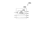
- the configurations of the transmission processing units 208a to 208d of the mobile station devices 300a to 300d in the second embodiment will be described with reference to FIGS.
- the number of transmission antennas N t is 4.
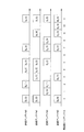
- the signal A 1 (m) at the time t of the second layer and the signal A 2 (m) at the time t of the third layer are not input to the STBC encoding unit 216 but are output as they are. Also, the signal B 1 (m) at the time t + 1 of the second layer and the signal B 2 (m) at the time t + 1 of the third layer are not input to the STBC encoding unit 216 but are output as they are.
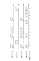
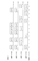
- the frequency indexes 1, 2, 5, 7, 8, and 11 have the first to sixth frequency domain signals (B 1 (0) to B 1 ( 5)) are assigned in order.
- frequency indexes 0, 3, 7, 9, 10, and 11 have the first to sixth frequency domain signals (B 2 (0) to B 2 ( 5)) are assigned in order.
- the allocation information generation unit 112 performs frequency allocation for the mobile station device 300b so that the transmission antenna # 0 and the transmission antenna # 1 are the same as shown in FIG. 13 and FIG. 2 and transmission antenna # 3 are each independently assigned an arbitrary frequency.
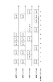
- the STBC encoding the encoding shown in FIGS. 13 and 14 is performed. However, at time t + 1, minus is added to the transmitting antenna # 1 instead of the transmitting antenna # 0, or the complex conjugate that is attached to the transmitting antenna # 0 at time t + 1. May be attached to the transmitting antenna # 1 at time t.
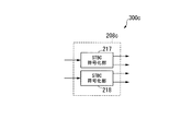
- FIG. 15 is a schematic block diagram illustrating a configuration of the transmission processing unit 208c of the mobile station device 300c.
- Number of transmit antennas N t of the mobile station apparatus 300b is a 4, rank R is 2.
- the transmission processing unit 208c includes an STBC encoding unit 217 and an STBC encoding unit 218.
- the STBC encoding unit 217 performs STBC encoding on the first layer
- the STBC encoding unit 218 performs STBC encoding on the second layer.
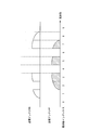
- the allocation information generation unit 112 has the same frequency allocation for the transmission antenna # 0 and the transmission antenna # 1, and the frequency allocation for the transmission antenna # 2 and the transmission antenna # 3 is the same. The frequency allocation is determined so that
- STBC is applied in the frequency domain.
- transmission processing units 208a to 208d may be arranged after IFFT, and STBC may be applied in the time domain.
- STBC may be applied in the time domain.
- it is applicable if it is the technique which transmits the information regarding the same data, such as SFBC and CDD, from the different antenna at the same time and the same frequency.
- it is also possible to use a technique (layer shift) in which the above technique is further multiplied by a precoding matrix as shown in the first embodiment, or a transmission antenna is switched between layers (layer shift).
- the transmission processing unit 208c has two STBC encoding units 217 and 218, but different transmission diversity techniques such as STBC and SFBC may exist in the transmission processing unit 208c.
- a program for realizing a part of the functions of the mobile station apparatus and the base station apparatus in each of the above embodiments is recorded on a computer-readable recording medium, and the program recorded on the recording medium is stored in each apparatus.
- the above functions may be realized by being read and executed by a computer system included in the above.
- the “computer system” includes an OS and hardware such as peripheral devices.
- the “computer-readable recording medium” means a storage device such as a flexible disk, a magneto-optical disk, a portable medium such as a ROM and a CD-ROM, and a hard disk incorporated in a computer system. Furthermore, the “computer-readable recording medium” dynamically holds a program for a short time like a communication line when transmitting a program via a network such as the Internet or a communication line such as a telephone line. In this case, a volatile memory in a computer system serving as a server or a client in that case, and a program that holds a program for a certain period of time are also included.
- the program may be a program for realizing a part of the functions described above, and may be a program capable of realizing the functions described above in combination with a program already recorded in a computer system.
- the present invention can be used in a mobile communication system in which a mobile phone device is a terminal device.
- 10 wireless communication system 100 ... base station apparatus 101-1, ⁇ 101-N r ... receiving antenna 102-1, ⁇ 102-N r ... OFDM signal receiving unit 103-1, ⁇ 103-N r ... reference signal separation unit 104-1, ⁇ 104-N r ... demapping section 105 ... equalizer 106-1, ⁇ 106-R m ... IDFT section 107-1, ⁇ 107-R m ... demodulation unit 108-1, ⁇ 108-R m ... decoding unit 109 ... P / S converting unit 110 ... channel estimating portion 111 ... equalization weight generating section 112 ... allocation information generation unit 113 ... transmitting portion 114 ...
Landscapes
- Engineering & Computer Science (AREA)
- Computer Networks & Wireless Communication (AREA)
- Signal Processing (AREA)
- Radio Transmission System (AREA)
- Mobile Radio Communication Systems (AREA)
Abstract
La présente invention concerne un système de communications hertziennes comportant : un premier appareil de communications hertziennes doté d'une pluralité d'antennes d'émission et utilisant un schéma MIMO pour émettre des signaux ; et un deuxième appareil de communications hertziennes qui reçoit les signaux. Lorsque le premier appareil de communications hertziennes effectue une émission d'un rang inférieur au nombre d'antennes d'émission, le premier appareil de communications hertziennes attribue la même fréquence à celles de la pluralité d'antennes d'émission à partir desquelles les mêmes données sont émises.
Priority Applications (1)
| Application Number | Priority Date | Filing Date | Title |
|---|---|---|---|
| US13/640,925 US9071307B2 (en) | 2010-04-15 | 2011-04-14 | Wireless communication system, wireless communication apparatus, program and transmission method |
Applications Claiming Priority (2)
| Application Number | Priority Date | Filing Date | Title |
|---|---|---|---|
| JP2010-094037 | 2010-04-15 | ||
| JP2010094037A JP5630898B2 (ja) | 2010-04-15 | 2010-04-15 | 基地局装置、端末装置、および無線通信システム |
Publications (1)
| Publication Number | Publication Date |
|---|---|
| WO2011129403A1 true WO2011129403A1 (fr) | 2011-10-20 |
Family
ID=44798772
Family Applications (1)
| Application Number | Title | Priority Date | Filing Date |
|---|---|---|---|
| PCT/JP2011/059286 Ceased WO2011129403A1 (fr) | 2010-04-15 | 2011-04-14 | Système de communications hertziennes, appareil de communications hertziennes, programme et procédé d'émission |
Country Status (3)
| Country | Link |
|---|---|
| US (1) | US9071307B2 (fr) |
| JP (1) | JP5630898B2 (fr) |
| WO (1) | WO2011129403A1 (fr) |
Families Citing this family (4)
| Publication number | Priority date | Publication date | Assignee | Title |
|---|---|---|---|---|
| US9374724B2 (en) * | 2011-11-03 | 2016-06-21 | Telefonaktiebolaget Lm Ericsson (Publ) | Channel estimation using reference signals |
| CN103209487A (zh) * | 2012-01-17 | 2013-07-17 | 中兴通讯股份有限公司 | 一种无线通信方法和通信装置及通信系统 |
| CN109417522B (zh) * | 2016-09-28 | 2020-12-04 | Oppo广东移动通信有限公司 | 传输数据的方法、接收端设备和发送端设备 |
| CN110855414B (zh) * | 2019-11-18 | 2021-11-26 | 展讯通信(上海)有限公司 | 下行译码方法、装置、用户设备及存储介质 |
Citations (1)
| Publication number | Priority date | Publication date | Assignee | Title |
|---|---|---|---|---|
| JP2008079262A (ja) * | 2006-08-22 | 2008-04-03 | Ntt Docomo Inc | 下りリンクmimo伝送制御方法および基地局装置 |
Family Cites Families (6)
| Publication number | Priority date | Publication date | Assignee | Title |
|---|---|---|---|---|
| JP4387414B2 (ja) * | 2004-09-27 | 2009-12-16 | シャープ株式会社 | 無線送信装置 |
| JP4884722B2 (ja) * | 2005-03-31 | 2012-02-29 | 株式会社エヌ・ティ・ティ・ドコモ | 無線通信装置及び無線通信方法 |
| US8111782B2 (en) * | 2006-08-31 | 2012-02-07 | Samsung Electronics Co., Ltd. | Apparatus and method for transmitting/receiving data in a multi-antenna system, and system using the same |
| EP2180624B1 (fr) | 2007-08-13 | 2020-08-05 | Sharp Kabushiki Kaisha | Station de base de radiocommunication |
| JPWO2009022599A1 (ja) * | 2007-08-14 | 2010-11-11 | 株式会社エヌ・ティ・ティ・ドコモ | 受信装置及びデータ取得方法 |
| JP5455912B2 (ja) * | 2008-08-12 | 2014-03-26 | パナソニック株式会社 | 基地局装置、端末装置、および、送信方法 |
-
2010
- 2010-04-15 JP JP2010094037A patent/JP5630898B2/ja not_active Expired - Fee Related
-
2011
- 2011-04-14 US US13/640,925 patent/US9071307B2/en not_active Expired - Fee Related
- 2011-04-14 WO PCT/JP2011/059286 patent/WO2011129403A1/fr not_active Ceased
Patent Citations (1)
| Publication number | Priority date | Publication date | Assignee | Title |
|---|---|---|---|---|
| JP2008079262A (ja) * | 2006-08-22 | 2008-04-03 | Ntt Docomo Inc | 下りリンクmimo伝送制御方法および基地局装置 |
Also Published As
| Publication number | Publication date |
|---|---|
| US20130028226A1 (en) | 2013-01-31 |
| JP5630898B2 (ja) | 2014-11-26 |
| JP2011228786A (ja) | 2011-11-10 |
| US9071307B2 (en) | 2015-06-30 |
Similar Documents
| Publication | Publication Date | Title |
|---|---|---|
| USRE49159E1 (en) | Method and apparatus of transmitting reference signal for uplink transmission | |
| KR101658776B1 (ko) | 통신 장치 및 통신 방법 | |
| US9219587B2 (en) | Method and apparatus for transmitting reference signal in multi-antenna system | |
| CN102414999B (zh) | 用于在无线通信系统中发射参考信号的装置和方法 | |
| CN104135346B (zh) | 无线通信系统、无线通信装置及无线通信方法 | |
| JP5364722B2 (ja) | 端末装置およびマッピング方法 | |
| CN102160313B (zh) | 基站装置、用户装置和预编码方法 | |
| CN105846875A (zh) | 无线基站、用户终端、无线通信系统以及无线通信方法 | |
| TW200835255A (en) | Joint use of multi-carrier and single-carrier multiplexing schemes for wireless communication | |
| JP2012222722A (ja) | 無線通信システム、移動局装置および基地局装置 | |
| JP6316204B2 (ja) | 基地局装置、無線通信システム、無線通信方法および集積回路 | |
| US8824600B2 (en) | Multiuser MIMO system, receiver, and transmitter | |
| JP5630898B2 (ja) | 基地局装置、端末装置、および無線通信システム | |
| JP2012175335A (ja) | 無線通信システム、無線通信方法、送信装置、及びプロセッサ | |
| JP2010245641A (ja) | 無線システム、基地局装置、移動局装置、通信方法、プログラム | |
| Takeda et al. | Investigation of two-dimensional orthogonal sequence mapping to multi-layer reference signal for LTE-advanced downlink | |
| Taskin | Performance Analysis for WiMAX Wireless Systems with Multiple Receive Antennas | |
| HK1139803B (en) | Ofdm system with subcarrier group phase rotation | |
| HK1139805B (en) | Ofdm transmitter with subcarrier group phase rotation |
Legal Events
| Date | Code | Title | Description |
|---|---|---|---|
| 121 | Ep: the epo has been informed by wipo that ep was designated in this application |
Ref document number: 11768924 Country of ref document: EP Kind code of ref document: A1 |
|
| WWE | Wipo information: entry into national phase |
Ref document number: 13640925 Country of ref document: US |
|
| NENP | Non-entry into the national phase |
Ref country code: DE |
|
| 122 | Ep: pct application non-entry in european phase |
Ref document number: 11768924 Country of ref document: EP Kind code of ref document: A1 |