WO2011132380A1 - 現像剤担持体、それを用いた現像装置 - Google Patents
現像剤担持体、それを用いた現像装置 Download PDFInfo
- Publication number
- WO2011132380A1 WO2011132380A1 PCT/JP2011/002153 JP2011002153W WO2011132380A1 WO 2011132380 A1 WO2011132380 A1 WO 2011132380A1 JP 2011002153 W JP2011002153 W JP 2011002153W WO 2011132380 A1 WO2011132380 A1 WO 2011132380A1
- Authority
- WO
- WIPO (PCT)
- Prior art keywords
- group
- resin
- developer
- carbon black
- toner
- Prior art date
- Legal status (The legal status is an assumption and is not a legal conclusion. Google has not performed a legal analysis and makes no representation as to the accuracy of the status listed.)
- Ceased
Links
Images

Classifications
-
- G—PHYSICS
- G03—PHOTOGRAPHY; CINEMATOGRAPHY; ANALOGOUS TECHNIQUES USING WAVES OTHER THAN OPTICAL WAVES; ELECTROGRAPHY; HOLOGRAPHY
- G03G—ELECTROGRAPHY; ELECTROPHOTOGRAPHY; MAGNETOGRAPHY
- G03G15/00—Apparatus for electrographic processes using a charge pattern
- G03G15/06—Apparatus for electrographic processes using a charge pattern for developing
- G03G15/08—Apparatus for electrographic processes using a charge pattern for developing using a solid developer, e.g. powder developer
- G03G15/0806—Apparatus for electrographic processes using a charge pattern for developing using a solid developer, e.g. powder developer on a donor element, e.g. belt, roller
- G03G15/0818—Apparatus for electrographic processes using a charge pattern for developing using a solid developer, e.g. powder developer on a donor element, e.g. belt, roller characterised by the structure of the donor member, e.g. surface properties
-
- C—CHEMISTRY; METALLURGY
- C08—ORGANIC MACROMOLECULAR COMPOUNDS; THEIR PREPARATION OR CHEMICAL WORKING-UP; COMPOSITIONS BASED THEREON
- C08F—MACROMOLECULAR COMPOUNDS OBTAINED BY REACTIONS ONLY INVOLVING CARBON-TO-CARBON UNSATURATED BONDS
- C08F12/00—Homopolymers and copolymers of compounds having one or more unsaturated aliphatic radicals, each having only one carbon-to-carbon double bond, and at least one being terminated by an aromatic carbocyclic ring
- C08F12/02—Monomers containing only one unsaturated aliphatic radical
- C08F12/04—Monomers containing only one unsaturated aliphatic radical containing one ring
- C08F12/14—Monomers containing only one unsaturated aliphatic radical containing one ring substituted by hetero atoms or groups containing heteroatoms
- C08F12/26—Nitrogen
- C08F12/28—Amines
-
- C—CHEMISTRY; METALLURGY
- C08—ORGANIC MACROMOLECULAR COMPOUNDS; THEIR PREPARATION OR CHEMICAL WORKING-UP; COMPOSITIONS BASED THEREON
- C08F—MACROMOLECULAR COMPOUNDS OBTAINED BY REACTIONS ONLY INVOLVING CARBON-TO-CARBON UNSATURATED BONDS
- C08F120/00—Homopolymers of compounds having one or more unsaturated aliphatic radicals, each having only one carbon-to-carbon double bond, and only one being terminated by only one carboxyl radical or a salt, anhydride, ester, amide, imide or nitrile thereof
- C08F120/02—Monocarboxylic acids having less than ten carbon atoms; Derivatives thereof
- C08F120/10—Esters
- C08F120/34—Esters containing nitrogen, e.g. N,N-dimethylaminoethyl (meth)acrylate
-
- C—CHEMISTRY; METALLURGY
- C08—ORGANIC MACROMOLECULAR COMPOUNDS; THEIR PREPARATION OR CHEMICAL WORKING-UP; COMPOSITIONS BASED THEREON
- C08F—MACROMOLECULAR COMPOUNDS OBTAINED BY REACTIONS ONLY INVOLVING CARBON-TO-CARBON UNSATURATED BONDS
- C08F120/00—Homopolymers of compounds having one or more unsaturated aliphatic radicals, each having only one carbon-to-carbon double bond, and only one being terminated by only one carboxyl radical or a salt, anhydride, ester, amide, imide or nitrile thereof
- C08F120/02—Monocarboxylic acids having less than ten carbon atoms; Derivatives thereof
- C08F120/52—Amides or imides
- C08F120/54—Amides, e.g. N,N-dimethylacrylamide or N-isopropylacrylamide
- C08F120/60—Amides, e.g. N,N-dimethylacrylamide or N-isopropylacrylamide containing nitrogen in addition to the carbonamido nitrogen
-
- C—CHEMISTRY; METALLURGY
- C08—ORGANIC MACROMOLECULAR COMPOUNDS; THEIR PREPARATION OR CHEMICAL WORKING-UP; COMPOSITIONS BASED THEREON
- C08F—MACROMOLECULAR COMPOUNDS OBTAINED BY REACTIONS ONLY INVOLVING CARBON-TO-CARBON UNSATURATED BONDS
- C08F212/00—Copolymers of compounds having one or more unsaturated aliphatic radicals, each having only one carbon-to-carbon double bond, and at least one being terminated by an aromatic carbocyclic ring
- C08F212/02—Monomers containing only one unsaturated aliphatic radical
- C08F212/04—Monomers containing only one unsaturated aliphatic radical containing one ring
- C08F212/06—Hydrocarbons
- C08F212/08—Styrene
-
- C—CHEMISTRY; METALLURGY
- C08—ORGANIC MACROMOLECULAR COMPOUNDS; THEIR PREPARATION OR CHEMICAL WORKING-UP; COMPOSITIONS BASED THEREON
- C08F—MACROMOLECULAR COMPOUNDS OBTAINED BY REACTIONS ONLY INVOLVING CARBON-TO-CARBON UNSATURATED BONDS
- C08F220/00—Copolymers of compounds having one or more unsaturated aliphatic radicals, each having only one carbon-to-carbon double bond, and only one being terminated by only one carboxyl radical or a salt, anhydride ester, amide, imide or nitrile thereof
- C08F220/02—Monocarboxylic acids having less than ten carbon atoms; Derivatives thereof
- C08F220/10—Esters
- C08F220/34—Esters containing nitrogen, e.g. N,N-dimethylaminoethyl (meth)acrylate
-
- C—CHEMISTRY; METALLURGY
- C08—ORGANIC MACROMOLECULAR COMPOUNDS; THEIR PREPARATION OR CHEMICAL WORKING-UP; COMPOSITIONS BASED THEREON
- C08K—Use of inorganic or non-macromolecular organic substances as compounding ingredients
- C08K3/00—Use of inorganic substances as compounding ingredients
- C08K3/02—Elements
- C08K3/04—Carbon
-
- C—CHEMISTRY; METALLURGY
- C08—ORGANIC MACROMOLECULAR COMPOUNDS; THEIR PREPARATION OR CHEMICAL WORKING-UP; COMPOSITIONS BASED THEREON
- C08L—COMPOSITIONS OF MACROMOLECULAR COMPOUNDS
- C08L33/00—Compositions of homopolymers or copolymers of compounds having one or more unsaturated aliphatic radicals, each having only one carbon-to-carbon double bond, and only one being terminated by only one carboxyl radical, or of salts, anhydrides, esters, amides, imides or nitriles thereof; Compositions of derivatives of such polymers
- C08L33/04—Homopolymers or copolymers of esters
- C08L33/14—Homopolymers or copolymers of esters of esters containing halogen, nitrogen, sulfur, or oxygen atoms in addition to the carboxy oxygen
-
- C—CHEMISTRY; METALLURGY
- C09—DYES; PAINTS; POLISHES; NATURAL RESINS; ADHESIVES; COMPOSITIONS NOT OTHERWISE PROVIDED FOR; APPLICATIONS OF MATERIALS NOT OTHERWISE PROVIDED FOR
- C09D—COATING COMPOSITIONS, e.g. PAINTS, VARNISHES OR LACQUERS; FILLING PASTES; CHEMICAL PAINT OR INK REMOVERS; INKS; CORRECTING FLUIDS; WOODSTAINS; PASTES OR SOLIDS FOR COLOURING OR PRINTING; USE OF MATERIALS THEREFOR
- C09D133/00—Coating compositions based on homopolymers or copolymers of compounds having one or more unsaturated aliphatic radicals, each having only one carbon-to-carbon double bond, and at least one being terminated by only one carboxyl radical, or of salts, anhydrides, esters, amides, imides, or nitriles thereof; Coating compositions based on derivatives of such polymers
- C09D133/04—Homopolymers or copolymers of esters
- C09D133/14—Homopolymers or copolymers of esters of esters containing halogen, nitrogen, sulfur or oxygen atoms in addition to the carboxy oxygen
-
- C—CHEMISTRY; METALLURGY
- C08—ORGANIC MACROMOLECULAR COMPOUNDS; THEIR PREPARATION OR CHEMICAL WORKING-UP; COMPOSITIONS BASED THEREON
- C08F—MACROMOLECULAR COMPOUNDS OBTAINED BY REACTIONS ONLY INVOLVING CARBON-TO-CARBON UNSATURATED BONDS
- C08F220/00—Copolymers of compounds having one or more unsaturated aliphatic radicals, each having only one carbon-to-carbon double bond, and only one being terminated by only one carboxyl radical or a salt, anhydride ester, amide, imide or nitrile thereof
- C08F220/02—Monocarboxylic acids having less than ten carbon atoms; Derivatives thereof
- C08F220/10—Esters
- C08F220/12—Esters of monohydric alcohols or phenols
- C08F220/16—Esters of monohydric alcohols or phenols of phenols or of alcohols containing two or more carbon atoms
- C08F220/18—Esters of monohydric alcohols or phenols of phenols or of alcohols containing two or more carbon atoms with acrylic or methacrylic acids
- C08F220/1808—C8-(meth)acrylate, e.g. isooctyl (meth)acrylate or 2-ethylhexyl (meth)acrylate
-
- C—CHEMISTRY; METALLURGY
- C08—ORGANIC MACROMOLECULAR COMPOUNDS; THEIR PREPARATION OR CHEMICAL WORKING-UP; COMPOSITIONS BASED THEREON
- C08K—Use of inorganic or non-macromolecular organic substances as compounding ingredients
- C08K5/00—Use of organic ingredients
- C08K5/04—Oxygen-containing compounds
- C08K5/05—Alcohols; Metal alcoholates
-
- G—PHYSICS
- G03—PHOTOGRAPHY; CINEMATOGRAPHY; ANALOGOUS TECHNIQUES USING WAVES OTHER THAN OPTICAL WAVES; ELECTROGRAPHY; HOLOGRAPHY
- G03G—ELECTROGRAPHY; ELECTROPHOTOGRAPHY; MAGNETOGRAPHY
- G03G2215/00—Apparatus for electrophotographic processes
- G03G2215/06—Developing structures, details
- G03G2215/0634—Developing device
-
- Y—GENERAL TAGGING OF NEW TECHNOLOGICAL DEVELOPMENTS; GENERAL TAGGING OF CROSS-SECTIONAL TECHNOLOGIES SPANNING OVER SEVERAL SECTIONS OF THE IPC; TECHNICAL SUBJECTS COVERED BY FORMER USPC CROSS-REFERENCE ART COLLECTIONS [XRACs] AND DIGESTS
- Y10—TECHNICAL SUBJECTS COVERED BY FORMER USPC
- Y10T—TECHNICAL SUBJECTS COVERED BY FORMER US CLASSIFICATION
- Y10T428/00—Stock material or miscellaneous articles
- Y10T428/25—Web or sheet containing structurally defined element or component and including a second component containing structurally defined particles
Definitions
- the present invention relates to a developer carrying member and a developing device used in an image forming apparatus.
- Patent Document 1 a resin layer containing a charge control agent is provided on the surface of a developer carrying member to control the triboelectric charge amount distribution.
- Patent Document 2 proposes a developer carrier comprising a resin layer containing a quaternary ammonium base-containing copolymer as a charge control agent. According to this configuration, the negative electrode counter ion of the quaternary ammonium base is ionized, so that the charge control agent becomes ion conductive, and the volume resistance of the resin layer is reduced to some extent. Thereby, image defects such as ghost and fog are improved.
- Patent Document 3 proposes a developer carrying member comprising a positively chargeable resin and specific carbon black in a resin layer. With such a configuration, by using carbon black having a small particle size and lubricity, uniform and high frictional charging can be imparted to the toner. Further, contamination of the surface of the developer carrying member due to toner fusion or toner adhesion can be suppressed.
- an object of the present invention is to provide a uniform triboelectric charge amount distribution while quickly imparting a sufficiently high triboelectric charge property to a toner even after long-term use, and a developer excellent in stain resistance.
- the present invention provides a carrier and a developing device using the same.
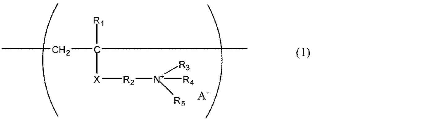
- the developer carrier according to the present invention is a developer carrier having a substrate and a resin layer formed on the surface of the substrate, and the resin layer is obtained by heating a coating composition containing the following (A) to (E): It is obtained by curing: (A) Thermosetting resin as binder resin (B) C1-C4 alcohol as solvent (C) Resin having unit represented by following formula (1) (D) Measured by X-ray diffraction Graphitized carbon black (E) acidic carbon black having a pH of 5.0 or less, wherein the spacing of the graphite (002) plane is 0.3370 nm or more and 0.3450 nm or less
- R 1 represents a hydrogen atom or a methyl group
- R 2 represents an alkylene group having 1 to 4 carbon atoms.
- One or more selected from R 3 , R 4 and R 5 represents an alkyl group having 4 to 18 carbon atoms, and the remaining groups represent an alkyl group having 1 to 3 carbon atoms.
- X is —COO—, —CONH— or —C 6 H 4 —.
- a ⁇ represents an anion.
- a developing device includes a developer having toner particles, a container containing the developer, and a developer carrying member for carrying and transporting the developer contained in the container.
- a developing device having the developer carrying member is the developer carrying member described above.
- the present invention even when used for a long period of time, it is possible to provide a uniform triboelectric charge distribution while quickly imparting a sufficiently high triboelectric chargeability to the toner, and also to carry a developer excellent in stain resistance. You can get a body.
- a developing device is provided that contributes to the stable formation of high-quality electrophotographic images in which blotches and ghosts are suppressed.
- the developer carrier according to the present invention has a base and a resin layer formed on the surface of the base.
- the resin layer is obtained by thermosetting a coating composition containing the following (A) to (E).
- E Acidic carbon black having a pH of 5.0 or less.
- R 1 represents a hydrogen atom or a methyl group
- R 2 represents an alkylene group having 1 to 4 carbon atoms
- One or more selected from R 3 , R 4 and R 5 represents an alkyl group having 4 to 18 carbon atoms, and the remaining groups represent an alkyl group having 1 to 3 carbon atoms.
- X is —COO—, —CONH— or —C 6 H 4 —.
- a ⁇ represents an anion.
- the resin layer formed on the substrate surface of the developer carrying member of the present invention contains a thermosetting resin as a binder resin.
- a thermosetting resin As the thermosetting resin, phenol resin, melamine resin, urea resin, and benzoguanamine resin are particularly preferable in terms of toughness and durability.
- a phenol resin is more preferable because it improves the abrasion resistance of the resin layer, is excellent in environmental stability, and is compatible with the component (C) described later.
- these thermosetting resins those that are particularly soluble in lower alcohols such as methanol, ethanol, propyl alcohol, and butanol are preferable because of their particularly good compatibility with the component (C).
- the resin layer formed on the substrate surface of the developer carrying member of the present invention contains a resin containing at least the unit represented by the formula (1).
- a resin containing at least the unit represented by the formula (1) By including the resin containing the unit represented by the formula (1), it is possible to improve the triboelectric charge imparting ability of the resin layer to the toner.
- the unit represented by the formula (1) since the unit represented by the formula (1) has ionic conductivity, the conductivity of the resin layer is improved as compared with the conventional charge control agent, and excessive frictional charging with respect to the toner can be suppressed.
- R 1 is a methyl group
- R 2 is a methylene group or an ethylene group
- R 3 , R 4 and R 5 are selected from the group consisting of an octyl group, a nonyl group, a decyl group, an undecyl group, a dodecyl group, a tridecyl group and a tetradecyl group
- C the group which is not an octyl group, nonyl group, decyl group, undecyl group, dodecyl group, tridecyl group or tetradecyl group is any one selected from a methyl group, an ethyl group and a propyl group
- a ⁇ is an anion containing
- a long chain alkyl group having 4 to 18 carbon atoms is introduced into one or two or more selected from R 3 , R 4 and R 5 in the formula (1), whereby a unit which is a charged site is bonded. It will exist uniformly in the resin. As a result, it is possible to obtain a developer bearing member that can impart uniform frictional charge to the toner.
- R 3 is an octyl group, nonyl group, decyl group, undecyl group, dodecyl group, tridecyl group or tetradecyl group
- R 4 and R 5 are each independently a methyl group, an ethyl group or a propyl group. Is preferred.
- the unit represented by the formula (1) has a cationic property, as a result, the cationic unit is increased on the surface side of the resin layer, and a developer carrier having a further improved ability to impart negative charge to the toner can be obtained.
- a ⁇ is an anion in halogens, hydrochloric acid, hydrobromic acid, sulfuric acid, phosphoric acid, nitric acid and other inorganic acids, and carboxylic acid and sulfonic acid in organic acids.
- An anion containing a sulfur atom or a halogen atom is preferred, and a halogen such as Br— or Cl— is more preferred because of its good compatibility with the thermosetting resin.
- the resin as component (C) can be produced by polymerizing a monomer having a quaternary ammonium base.
- Examples of the monomer having a quaternary ammonium base include a monomer that is a unit represented by the following formula (2).
- a known polymerization method can be used to produce a resin that can be used as the component (C).
- the method include a bulk polymerization method, a solution polymerization method, an emulsion polymerization method, and a suspension polymerization method, but a solution polymerization method is preferable because the reaction can be easily controlled.
- Solvents used in the solution polymerization method are lower alcohols such as methanol, ethanol, n-butanol, and isopropyl alcohol.
- a solvent such as xylene, toluene, ethyl acetate, isobutyl acetate, methyl ethyl ketone, methyl isobutyl ketone, N, N-dimethylformamide, dimethylformamide may be mixed and used.
- a lower alcohol as a solvent.
- the ratio of the solvent and the monomer component is preferably 30 parts by mass or more and 400 parts by mass or less with respect to 100 parts by mass of the solvent from the viewpoint of the reaction rate of the monomer.
- the polymerization of the monomer can be performed, for example, by heating the monomer to a temperature of 50 ° C. or higher and 100 ° C. or lower in the presence of a polymerization initiator in an inert gas atmosphere.
- a polymerization initiator used in order to superpose
- t-butylperoxy-2-ethylhexanoate cumyl perpivalate, t-butylperoxylaurate, benzoyl peroxide, lauroyl peroxide, octanoyl peroxide, di-t-butyl peroxide, t-butyl Cumyl peroxide, dicumyl peroxide, 2,2'-azobisisobutyronitrile, 2,2'-azobis (2-methylbutyronitrile), 2,2'-azobis (2,4-dimethylvaleronitrile) ), 2,2′-azobis (4-methoxy-2,4-dimethylvaleronitrile), dimethyl 2,2′-azobis (2-methylpropionate).
- the polymerization initiators can be used alone or in combination of two or more monomers. Usually, a polymerization initiator is added to the monomer solution to initiate the polymerization, but a part of the polymerization initiator may be added during the polymerization step in order to reduce unreacted monomers. In addition, a method of promoting polymerization by irradiation with ultraviolet rays or an electron beam can be used, and these methods may be combined.
- the amount of the polymerization initiator used is preferably 0.05 parts by mass or more and 30 parts by mass or less with respect to 100 parts by mass of the monomer component from the viewpoint of reducing unreacted monomers and optimizing the reaction rate, and more preferably 0. .1 to 15 parts by mass.
- the temperature of the polymerization reaction can be set according to the composition of the solvent to be used, the polymerization initiator, and the monomer component. However, the reaction is performed at a temperature of 40 ° C. or higher and 150 ° C. or lower to optimize the reaction rate or to evaporate the solvent. It is preferable at the point which prevents.
- a monomer that is a unit represented by the formula (2) a monomer that is a unit represented by the following formula (3) that is quaternized with a quaternizing agent can be used.
- R 1 to R 4 and X in the formula (3) are the same as those in the formula (1).
- Alkyl halides (butyl bromide, 2-ethylhexyl bromide, octyl bromide, lauryl bromide, stearyl bromide, butyl chloride, 2-ethylhexyl chloride, octyl chloride, lauryl chloride, stearyl chloride, etc.)
- Organic acid compounds (such as methyl p-toluenesulfonate, dimethyl sulfate, and methyl hydroxynaphthalenesulfonate).
- the amount of the quaternizing agent used is preferably 0.8 mol or more and 1.0 mol or less with respect to 1 mol of the monomer which is a unit represented by the formula (3). This is because an unreacted quaternizing agent is eliminated and many monomers can be quaternized.
- the quaternization of the monomer can be performed, for example, by heating the monomer and the quaternizing agent to a temperature of 60 ° C. or higher and 90 ° C. or lower in a solvent.
- a desired quaternary ammonium base-containing polymer by polymerizing the monomer of the unit represented by the above formula (3) and then quaternizing with the quaternizing agent.
- the monomer of the unit represented by the formula (3) is quaternized with an alkyl halide such as methyl chloride and polymerized.
- the obtained quaternary ammonium base-containing polymer is treated with an acid such as p-toluenesulfonic acid or hydroxynaphthalene sulfonic acid to perform counterion exchange, and the quaternary ammonium base-containing polymer as a target anion species is obtained. It can also be combined.
- the resin as the component (C) may have one or more other units in addition to the unit represented by the formula (1).
- the content of other units contained in the resin is preferably 50 mol% or less of the total number of units [mol] constituting the resin. By making the content rate of another unit 50 mol% or less, it is easy to obtain the effect by introducing the unit represented by the formula (1).
- the compounding quantity of a component is 1 to 40 mass parts with respect to 100 mass parts of binder resin. By making the blending amount of the component (C) within this range, the effect of controlling tribocharging by adding to the thermosetting resin can be exhibited, and it can exist uniformly in the binder resin. Therefore, a uniform toner triboelectric charge amount distribution can be obtained.
- the resin including the unit represented by the formula (1) and other units include, for example, a resin containing a unit represented by the formula (1) and a unit represented by the following formula (4). .
- R 6 represents a hydrogen atom or a methyl group
- R 7 represents an alkyl group having 8 to 18 carbon atoms.
- a more preferred form of the unit represented by formula (4) is a long-chain alkyl group selected from R 6 is a methyl group, and R 7 is a decyl group, an undecyl group, a dodecyl group, a tridecyl group, or a tetradecyl group. is there.
- R 6 is a methyl group
- R 7 is a decyl group, an undecyl group, a dodecyl group, a tridecyl group, or a tetradecyl group. is there.
- R 7 an alkyl group having 8 to 18 carbon atoms
- the hydrophobicity can be relatively increased, so that the compatibility of the component (C) with the binder resin is maintained.
- the component (C) can be present more uniformly in the resin layer.
- R 7 a long-chain alkyl group having 18 or less carbon atoms, it is possible to suppress a decrease in compatibility between the component (C) and the binder resin or solvent due to an increase in crystallinity of the component (C).
- the crystallinity of the component (C) is too high, phase separation from the binder resin is easy, and therefore the presence of the component (C) in the binder resin tends to be uneven.
- the toner in contact with such a resin layer tends to have a non-uniform distribution of triboelectric charge.
- the resin layer containing the ion conductive resin as the component (C) needs to have conductivity in order to allow the excess charge to flow through the resin layer when the toner is excessively charged. Therefore, it is necessary to contain conductive particles in the resin layer.
- conductive particles when the conductive particles are contained in the resin layer together with the component (C), it is important that the conductive particles are not aggregated in the resin layer. If the aggregates of the conductive particles are unevenly present in the resin layer, the excessive charge of the excessively charged toner cannot be smoothly flowed to the resin layer, which is caused by the excessively charged toner in the electrophotographic image. In some cases, image defects such as ghosts and blotches may occur. That is, in order to obtain a resin layer that can uniformly apply a high triboelectric charge to the toner, it is necessary to improve the surface lubricity of the resin layer and to make the conductive agent uniformly exist in the resin layer.
- ⁇ (D), (E) component> The present inventors have found that the above problem can be solved by using both graphitized carbon black and acidic carbon black as a conductive agent. That is, the graphitized carbon black is electrically neutral because the functional group is removed during the graphitization process. Therefore, graphitized carbon black tends to aggregate. However, when the graphitized carbon black was dispersed together with the acidic carbon black during the preparation of the coating for forming the resin layer, the aggregate of the graphitized carbon black was gradually loosened, and the graphitized carbon black was uniformly dispersed. A paint can be obtained. Further, by using such a paint, it is possible to obtain a developer carrier having a resin layer in which graphitized carbon black is uniformly dispersed.
- a paint in which the graphitized carbon black is uniformly dispersed can be obtained by dispersing the graphitized carbon black together with the acidic carbon black in the preparation of the paint for forming the resin layer.
- acidic carbon blacks having a pH of 5.0 or less are known to have repulsive force and have very good dispersibility in an alcohol-based resin solution. That is, it is uniformly dispersed in the paint.
- acidic carbon black is relatively negatively charged.
- graphitized carbon black gradually exhibits positive chargeability by contact with acidic carbon black. As a result, it is considered that the acid carbon black that is uniformly dispersed is electrically attracted to loosen the aggregation.
- the graphitized carbon black of component (D) has a plane spacing of 0.3370 nm to 0.3450 nm on the graphite (002) plane obtained from X-ray diffraction. It is known that the hexagonal mesh planes of carbon atoms are regularly stacked and the plane spacing of (002) plane of graphite having a complete graphite structure is 0.3354 nm (3.354 angstrom). Further, it is known that the plane spacing of a carbon precursor having a crystal structure that is not as developed as that of graphite is 0.3470 to 0.3600 nm (3.47 to 3.60 angstroms).
- the value of the interplanar spacing of the graphite (002) plane is a parameter indicating the degree of development of graphite-like crystallization. Therefore, although the graphitized carbon black according to the present invention has a fairly high regularity of aromatic network planes, the regularity of the graphitized carbon black has reached the complete layered structure of graphite. Not in. Here, the hexagonal mesh planes of graphite (graphite) are only connected by van der Waals force, so the bonding force is weak. It has the characteristic that In addition, since there are ⁇ electrons that move like free electrons in the hexagonal mesh plane of graphite, high conductivity is exhibited.
- the graphitized carbon black according to the present invention has high lubricity and conductivity due to the graphite-like crystal structure on the surface and in the vicinity thereof as compared with ordinary carbon black. Therefore, the graphitized carbon black is better in terms of dispersibility in the paint than ordinary carbon black. Further, when the graphitized carbon black is contained in the resin layer, the adhesion of the toner to the surface of the developer carrier can be reduced due to the excellent self-lubricating property of the graphitized carbon black. In addition, when the graphitized carbon black is contained in the resin layer, the excellent conductivity of the graphitized carbon black can impart high conductivity to the resin layer, and developer support that contributes to suppression of excessive charging of the toner You can get a body.
- Such graphitized carbon black can be obtained by filling ordinary carbon black in a graphite crucible and firing at 1700 to 3200 ° C. in a non-oxidizing atmosphere.
- the graphitized carbon black according to the present invention is completely different from graphitized particles produced by firing bulk mesophase pitch or mesocarbon in a non-oxidizing atmosphere.
- Bulk mesophase pitch is an organic compound obtained by hydrogenating ⁇ -resin extracted from coal tar pitch by solvent fractionation.
- Mesocarbon microbeads are also organic compounds produced by polycondensing coal-based heavy oil or petroleum-based heavy oil and refining it. Bulk mesophase pitch and mesocarbon microbeads are known as graphitizable carbon materials.
- An easily graphitizable carbon material is a carbon material in which a graphite structure having a three-dimensional stacking regularity is easily formed by heat treatment at a high temperature of 2500 ° C. or more, and a mutual arrangement of crystal lattices such as coke is arranged. It is easy to change to a graphite structure. Therefore, graphitized particles obtained by firing bulk mesophase pitch or mesocarbon in a non-oxidizing atmosphere have been graphitized to the core.
- carbon black which is a raw material of component (D) is an inorganic compound. Carbon black is known as a non-graphitizable carbon material.
- the non-graphitizable carbon material refers to a carbon material that is extremely difficult to become graphite even when heated in an inert atmosphere.
- Carbon black is considered to have a curved surface structure composed of a carbon five-membered ring and a six-membered ring, or a planar structure in which no carbon six-membered ring is developed. Due to these three-dimensional restrictions, it is considered that carbon black does not easily change to a graphite structure.
- Carbon black has an average primary particle size as small as 10 to 100 nm, which is one of the reasons why it is difficult to obtain a graphite structure.
- graphitized carbon black as component (D) obtained from carbon black is graphitized up to the inside. It is considered that only the surface and its vicinity are graphitized. In this respect, the graphitized carbon black according to the present invention and the graphitized particles should be considered to be quite different.
- the graphitized carbon black according to the present invention may be modified by covalently bonding an organic group to the surface.
- a method for modifying the surface of graphitized carbon black for example, a method using an organometallic compound having at least one element selected from titanium, aluminum, zirconium and silicon, in the presence of a radical polymerization initiator And a method of heating.
- the blending amount of the component (D) is preferably 1 part by mass to 100 parts by mass with respect to 100 parts by mass of the component (A).
- the blending amount of component (E) is preferably 5 to 50 parts by mass with respect to 100 parts by mass of component (D).
- the presence of graphitized carbon black and acidic carbon black in the resin layer according to the present invention can be confirmed by a transmission electron microscope (TEM) or Raman spectroscopy.
- TEM transmission electron microscope
- Raman spectroscopy a conductive agent other than graphitized carbon black and acidic carbon black may be contained in the resin layer.
- the volume resistance of the resin layer of the developer carrier in the present invention is preferably 10 ⁇ 1 ⁇ ⁇ cm or more and 10 2 ⁇ ⁇ cm or less.
- the volume resistance of the resin layer of the developer carrying member is preferably 10 ⁇ 1 ⁇ ⁇ cm or more and 10 2 ⁇ ⁇ cm or less.
- rough particles for forming irregularities can be added.
- EPDM, NBR, SBR, CR rubber particles such as silicone rubber
- Elastomer particles such as polystyrene, polyolefin, polyvinyl chloride, polyurethane, polyester, polyamide-based thermoplastic elastomer (TPE); PMMA, urethane resin, fluororesin Resin particles such as silicone resin, phenol resin, naphthalene resin, furan resin, xylene resin, divinylbenzene polymer, styrene-divinylbenzene copolymer, polyacrylonitrile resin, alumina, zinc oxide, titanium oxide, tin oxide Oxide oxide particles; carbonized particles, conductive particles such as resin particles subjected to conductive treatment, and other organic compounds such as imidazole compounds
- Examples of the base of the developer carrying member used in the present invention include members such as a cylindrical member, a columnar member, and a belt-like member.
- a nonmagnetic metal or alloy such as aluminum, stainless steel, or brass is preferably used.
- a cylindrical member having a conductive shaft body and an elastic layer provided around the conductive shaft body is preferably used as a substrate in the case of using a developing method that directly contacts the photosensitive drum.
- a cylindrical member having a conductive shaft body and an elastic layer provided around the conductive shaft body is preferably used as the conductive shaft body.
- the conductive shaft body those having conductivity are used, and examples thereof include aluminum, iron, and stainless steel (SUS).
- the elastic layer silicone rubber, an elastomer such as EPDM or urethane, or other resin molding is used.
- a magnet roller in which a magnet is provided is disposed in the developer carrier.
- the base may be cylindrical and a magnet roller may be disposed inside the base.
- the resin layer can be formed, for example, by dispersing and mixing the components for the resin layer in a lower alcohol to form a paint, coating the substrate, drying and solidifying or curing.
- a known dispersion apparatus using beads such as a sand mill, a paint shaker, a dyno mill, and a pearl mill can be suitably used for dispersing and mixing each component into the coating liquid.
- a coating method a known method such as a dipping method, a spray method, or a roll coating method can be applied.
- the arithmetic average roughness Ra (JIS B0601-2001) is 0.4 ⁇ m or more and 2.0 ⁇ m or less.
- the thickness of the conductive resin coating layer it is 4 ⁇ m or more and 20 ⁇ m or less at which a uniform film thickness is easily obtained.
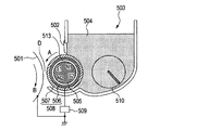
- FIG. 1 is a schematic cross-sectional view of a developing device according to an embodiment having the developer carrying member of the present invention.
- an electrostatic latent image carrier that holds an electrostatic latent image formed by a known process, for example, an electrophotographic photosensitive drum 501 is rotated in the direction of arrow B.
- a developing sleeve 508 as a developer carrying member carries a one-component developer 504 having magnetic toner supplied by a hopper 503 as a developer container containing the developer, and rotates in the direction of arrow A. .
- the developer 504 is conveyed to the developing area D where the developing sleeve 508 and the photosensitive drum 501 face each other.
- a magnet roller 505 in which a magnet is inscribed is disposed in the developing sleeve 508 in order to magnetically attract and hold the developer 504 on the developing sleeve 508.
- the developing sleeve 508 has a conductive resin coating layer 507 coated on a metal cylindrical tube 506 as a base.
- a stirring blade 510 for stirring the developer 504 is provided in the hopper 503, a stirring blade 510 for stirring the developer 504 is provided.
- Reference numeral 513 denotes a gap indicating that the developing sleeve 508 and the magnet net roller 505 are in a non-contact state.
- the developer 504 is a triboelectric charge capable of developing the electrostatic latent image on the photosensitive drum 501 by friction between the magnetic toners constituting the developer and the conductive resin coating layer 507 on the developing sleeve 508. Get. In the example of FIG.
- an elastic regulation blade 511 is used as a developer layer thickness regulating member in order to regulate the layer thickness of the developer 504 conveyed to the development area D.
- the elastic regulating blade 511 is made of a material having rubber elasticity such as urethane rubber or silicone rubber, or a material having metal elasticity such as phosphor bronze or stainless steel.
- the elastic regulating blade 511 is pressed in the direction opposite to the rotation direction of the developing sleeve 508. In these developing devices, a thin layer of developer is formed on the developing sleeve by elastically pressing the developer layer thickness regulating member to the developing sleeve 508 via the developer layer.
- the thickness of the thin layer of the developer 504 formed on the developing sleeve 508 is preferably thinner than the minimum gap between the developing sleeve 508 and the photosensitive drum 501 in the developing region D.
- the developer carrying member of the present invention is particularly effective when incorporated in a developing device that develops an electrostatic latent image with a thin layer of developer as described above, that is, a non-contact developing device.
- the developer carrier of the present invention is also applied to a developing device in which the thickness of the developer layer is equal to or greater than the minimum gap between the developing sleeve 508 and the photosensitive drum 501, that is, a contact type developing device. be able to.
- the following explanation will be made by taking the non-contact developing device as described above as an example.
- a developing bias voltage is applied to the developing sleeve 508 by a developing bias power source 509 as a biasing means in order to cause the one-component developer 504 having magnetic toner carried on the developing sleeve 508 to fly.
- a developing bias power source 509 As a biasing means, a voltage of a value between the potential of the image portion of the electrostatic latent image (the region visualized by the developer 504 attached) and the potential of the background portion is developed sleeve. It is preferable to apply to 508.
- a toner charged with a polarity opposite to that of the electrostatic latent image is visualized by attaching toner to the high potential portion of the electrostatic latent image having a high potential portion and a low potential portion.
- a toner that is charged to the same polarity as the polarity of the electrostatic latent image is used for visualization by attaching toner to the low potential portion of the electrostatic latent image having a high potential portion and a low potential portion.
- the high potential and the low potential are expressions based on absolute values. In any of these cases, the developer 504 is charged by at least friction with the developing sleeve 508.
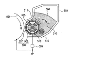
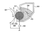
- FIG. 2 and 3 are schematic sectional views showing a developing device using magnetic toner.
- a magnetic regulating blade 502 made of a ferromagnetic metal is used as a developer layer thickness regulating member.
- the blade 502 is suspended from the hopper 503 so as to face the developing sleeve 508 with a gap width of about 50 to 500 ⁇ m from the surface of the developing sleeve 508.
- a magnetic force line from the magnetic pole N ⁇ b> 1 of the magnet roller 505 concentrates on the magnetic regulation blade 502, whereby a thin layer of the developer 504 is formed on the developing sleeve 508.
- a nonmagnetic blade can be used instead of the magnetic regulating blade 502. In the developing device of FIG.
- the elastic regulating blade 511 is in pressure contact with the rotation direction of the developing sleeve 508 in the forward direction, and a peeling member 512 is further installed.
- a roller member such as resin, rubber or sponge, a belt member, and a brush member are used.
- the roller-shaped peeling member 512 is rotated in the direction opposite to the developing sleeve 508.
- the developer that has not been transferred to the photosensitive drum 501 is temporarily peeled off from the sleeve surface by the stripping member 512, thereby preventing the generation of immobile toner on the sleeve and uniformizing the developer charge.
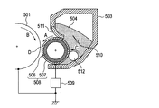
- FIG. 4 shows a developing device when a non-magnetic one-component developer is used as the toner 504. Since the toner is non-magnetic, there is no magnet in the developing sleeve, and a solid metal is used as the sleeve. A bar 514 is used. The nonmagnetic toner is triboelectrically charged by friction with the layer thickness regulating blade 511 or the sleeve coat layer 517, and is carried and conveyed on the surface of the developing sleeve 508.
- a stripping member 512 is provided in addition to the above.
- a metal cylindrical tube is used for the developing sleeve 508. 2 to 5 are the same as those of the developing apparatus shown in FIG. 1, and the components having the same reference numerals basically indicate the same members.
- the toner particles of the present invention can be produced by a pulverization method or a polymerization method.
- Toner particles having a high degree of spheroidization generally have a high charge amount, and depending on the usage situation, the triboelectric charge amount may become too high and charge up may occur.
- the developer-carrying member used in the present invention has an appropriate triboelectric charge-providing ability without causing charge-up even when the durability progresses from the beginning of use with respect to toner particles having such a high degree of spheroidization. Can be maintained. Therefore, the developer carrier of the present invention can be more suitably used in combination with such a highly spherical toner.
- the toner of the present invention preferably has a weight average particle diameter of 3 ⁇ m or more and 10 ⁇ m or less in order to faithfully develop finer latent image dots.
- the toner can contain a charge control agent in the toner particles (internal addition) or can be used by mixing with the toner particles (external addition).
- the toner is externally added with inorganic fine powders such as silica, titanium oxide, and alumina in order to improve environmental stability, triboelectric stability, developability, fluidity, storage stability and cleaning properties. That is, it is preferably present in the vicinity of the toner surface.
- the developer carrier used in the present invention provides uniform lubricity to the surface of the developer carrier by combining graphitized carbon black and acidic carbon black. Therefore, there is no harmful effect such as contamination of the developer carrier by the toner with respect to the toner using the wax having a low melting point, and the developer carrier of the present invention can be suitably used.
- the arithmetic average roughness (Ra) on the surface of the developer carrier is measured based on the surface roughness of JIS B0601 (2001) using a surf coder SE-3500 manufactured by Kosaka Laboratory.
- the evaluation length was 8 mm and the feed rate was 0.5 mm / s.
- the measurement position is a total of three positions, that is, a central position of the developer carrying member and an intermediate position between the central position and both ends of the coating, and further three places after rotating the 120 ° developer carrying member, and further 120 ° After rotating the developer carrying member, the same measurement was performed at three points, a total of nine points, and the average value was taken.
- the polymer structure of the additive resin was determined by analysis with a pyrolysis GC / MS apparatus “Voyager” (trade name, manufactured by Thermo Electron). In this analysis, thermal decomposition temperature: 600 ° C., column: HP-1 (15 m ⁇ 0.25 mm ⁇ 0.25 ⁇ m), Inlet: 300 ° C., Split: 20.0, injection amount: 1.2 ml / min, Temperature increase: performed at 50 ° C. (4 min) -300 ° C. (20 ° C./min).
- Graphitized carbon black powder was used as a measurement sample, and it was determined from an X-ray diffraction spectrum using a sample horizontal strong X-ray diffractometer “RINT / TTR-II” (trade name, manufactured by Rigaku Corporation). First, a non-reflective sample plate was filled with a measurement sample, and an X-ray diffraction chart was obtained using CuK ⁇ rays monochromatized by a monochromator as a radiation source.
- Optical system Parallel beam optical system goniometer: Rotor horizontal goniometer (TTR-2) Tube voltage / current: 50 kV / 300 mA Measurement method: Continuous scan axis: 2 ⁇ / ⁇ Measurement angle: 10 ° -50 ° Sampling interval: 0.02 ° Scanning speed: 4 ° / min Divergent slit: Open divergence longitudinal slit: 10 mm Scattering slit: Open light receiving slit: 1.00 mm
- the average circularity in the present invention is used as a simple method for quantitatively expressing the shape of particles.
- measurement is performed using a flow particle image analyzer “FPIA-1000” manufactured by Toago Medical Electronics, and the circularity (Ci) of each particle measured for a particle group having a circle-equivalent diameter of 3 ⁇ m or more is expressed by the following equation. I asked for each.
- the average circularity is a value obtained by arithmetically averaging the circularity of each particle.
- Circularity (Ci) (perimeter of a circle having the same projected area as the particle image) / (perimeter of the projected image of the particle) “FPIA-1000” as a measuring apparatus uses the following method for calculating the average circularity and the mode circularity after calculating the circularity of each particle.
- the method of calculating the average circularity using the center value and the frequency of the dividing points by classifying the particles with the circularity of 0.40 to 1.00 into 61 divided by 61 intervals according to the obtained circularity. is there.
- the average circularity in the present invention is an index of the degree of unevenness of particles, and indicates 1.000 when the particles are completely spherical, and the average circularity becomes smaller as the toner surface shape becomes more complicated.
- additive resin solutions B-2 to B-15 were obtained in the same manner as in the production example of additive resin solution B-1.
- the additive resin solution B-11 after the solution was formed, the ion was exchanged from bromine ions to p-toluenesulfonic acid ions using an ion exchange resin.
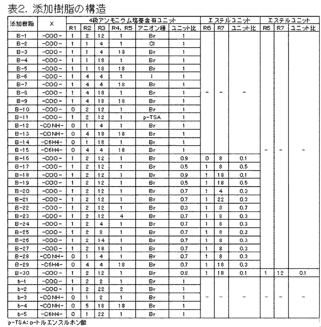
- the structures of the obtained additive resin solutions B-2 to B-15 are shown in Table 2.
- additive resin solutions B-17 to B-30 are the same as the manufacture example of the additive resin solution B-1 and the manufacture example of the additive resin solution B-16 except that the components used are those shown in Table 1. Got. The structures of the obtained additive resin solutions B-17 to B-30 are shown in Table 2.
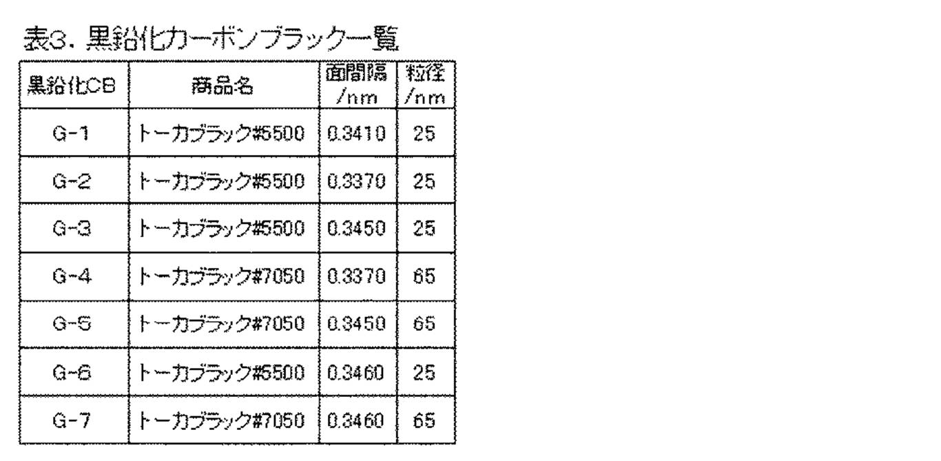
- G-2 to G-7 Graphitized carbon blacks G-2 to G-7 that can be used in the present invention are obtained by graphitizing carbon blacks having different particle sizes in the same manner as in the production example of graphitized carbon black G-1. Manufactured. The graphitization treatment was performed by filling carbon black in a graphite crucible and performing heat treatment at 1000 ° C. to 3000 ° C. in a nitrogen gas atmosphere. Table 3 shows the physical property values of the obtained graphitized carbon black.
- the coarsely pulverized product obtained by roughly pulverizing with a hammer mill is finely pulverized using a mechanical pulverizer turbo mill (manufactured by Turbo Kogyo Co., Ltd.), and then subjected to thermal spheronization treatment. I did it.
- the finely pulverized powder that has been subjected to thermal spheronization is classified and removed at the same time by using a multi-division classifier (Elbow Jet Classifier, manufactured by Nittetsu Mining Co., Ltd.) using the Coanda effect.
- Toner particles having a diameter (D4) of 6.0 ⁇ m and a circularity of 0.963 were obtained.
- Magnetic monocomponent toner 1 was obtained by adding 1.0 part of hydrophobic colloidal silica to 100 parts of the toner particles, and mixing and dispersing the mixture with a Henschel mixer.
- the prepared polymerizable monomer composition was put into the aqueous medium and suspended by stirring at 9,000 rpm using a TK homomixer at a temperature of 60 ° C. in a nitrogen atmosphere. Then, the temperature was raised to 70 ° C. over 3 hours while being transferred to a propeller type stirring device, and further heated up to 80 ° C. at a temperature raising rate of 40 ° C./hr after 4 hours. Reaction was performed for 5 hours to produce polymer particles. After completion of the polymerization reaction, the slurry containing the particles is cooled, washed with 10 times the amount of water of the slurry, filtered, and dried at a temperature of 6.67 ⁇ 10 ⁇ 1 kPa at a temperature of 40 ° C. for 48 hours. Magenta toner particles having a particle size adjusted by classification were obtained.
- a non-magnetic one-component toner 2 was obtained.
- the primary particle diameter of the hydrophobic silica fine powder was 10 nm, and the BET specific surface area was 170 m 2 / g.
- the obtained nonmagnetic one-component toner had a weight average particle diameter of 6.6 ⁇ m and an average circularity of 0.984.
- Example 1 ⁇ Preparation of paint intermediate> The following materials were mixed and dispersed in a sand mill using glass beads having a diameter of 1 mm as media particles for 2 hours to obtain a coating intermediate.
- Binder resin 1 20 parts as solid content
- Graphitized carbon black G-1 10 parts
- Acidic carbon black A-1 10 parts
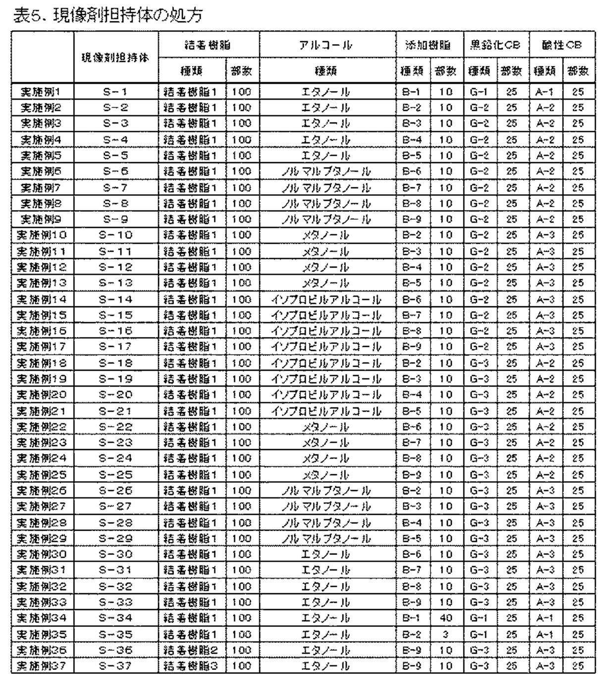
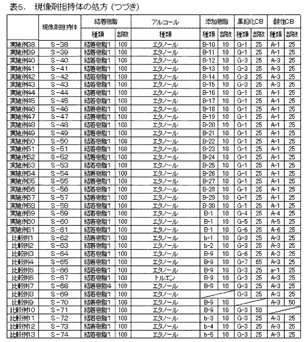
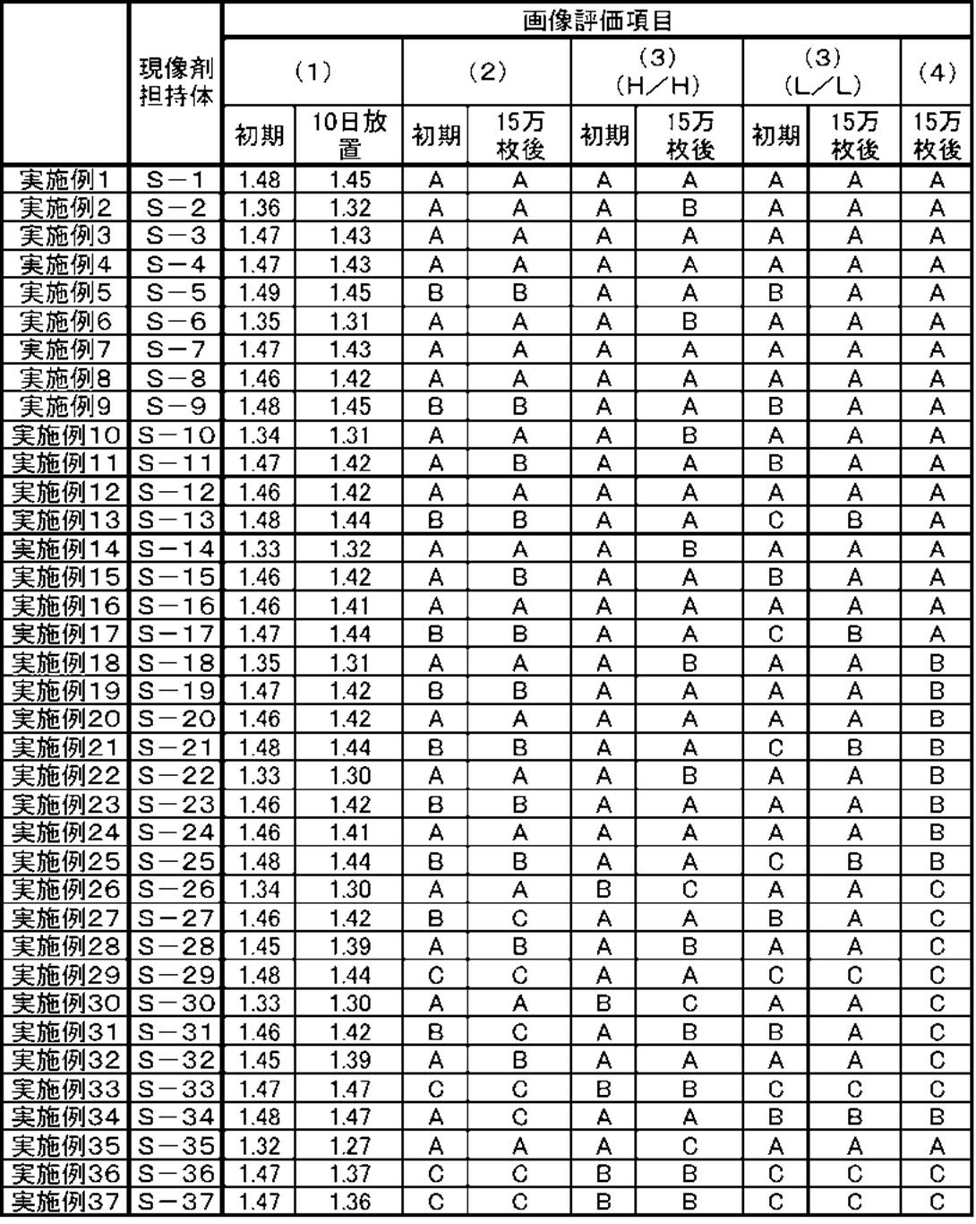
- Examples 2 to 61, Comparative Examples 1 to 13 Developing sleeves S-2 to S-74 were prepared and evaluated in the same manner as in Example 1 with the formulations listed in Table 5. The solid content concentration of the coating material for the resin layer was adjusted as appropriate. The results are shown in Table 6. As can be seen from the above results, by adding the additive resin of the present invention to the resin layer, a good image density was obtained even in a severe environment such as high temperature and high humidity. The image density was proportional to the triboelectric charge amount of the toner, and good evaluation results could be obtained by introducing a long chain alkyl group into the quaternary ammonium base.
- the copolymer of unit (1) and unit (4) was also evaluated.
- dispersibility in a solvent was further improved.
- the amount of the unit (4) is large, the triboelectric charge imparting ability tends to be small and the image density tends to be low.
- the structure of the unit (4) when the number of carbon atoms of the long-chain alkyl group is less than 8 or more than 18, the dispersibility of the added resin or the conductive agent in the solvent tends to be deteriorated. Image density, stain resistance, ghost, and evaluation of blotches and ghosts in an L / L environment tended to be relatively low.
- Comparative Example 3 and Comparative Example 4 graphitized carbon black having an interplanar spacing of the graphite (002) plane exceeding 0.3450 nm was used.
- Comparative Example 5 carbon black having a pH exceeding 5.0 was used.
- Comparative Example 8 the additive resin was evaluated, in Comparative Example 9, graphitized carbon black was evaluated, and in Comparative Example 10, acid carbon black was not added.
- Comparative Example 7 in which the additive resin was not added, the lack of frictional charge imparting ability with respect to the developer appeared remarkably, and a desired image density could not be obtained in the latter half of the durability.
- Comparative Example 3 and Comparative Example 4 in which the graphitized carbon black of the present invention was not added, the lack of lubricity of the developer carrier appeared remarkably, and contamination of the developer carrier in the H / H environment was confirmed. . Further, in Comparative Example 5 and Comparative Example 10 in which the acidic carbon black of the present invention is not added, the dispersibility of the graphitized carbon black is insufficient, so that the triboelectric charge amount distribution of the toner becomes non-uniform, such as ghosts and blotches. Image defect appeared.
- Example 62 ⁇ Preparation of paint intermediate> The following materials were mixed and dispersed in a sand mill using glass beads having a diameter of 1 mm as media particles for 2 hours to obtain a coating intermediate.
- -Binder resin 1 20 parts by mass as solid content-8 parts by mass of graphitized carbon black G-1-8 parts by mass of acidic carbon black A-1-Ethanol 50 parts by weight
- Developer carrier S-75 was incorporated into a magenta cartridge of a laser beam printer (trade name: LaserJet 5000, manufactured by Hewlett-Packard Company). Using the non-magnetic one-component toner 2, 6000 images were output with a character pattern with a printing ratio of 1% in the intermittent mode of 1 sheet / 10 seconds, and the following items (5) to (8) were evaluated. . As a result, as shown in Table 8, it was possible to obtain good developability from beginning to end under any environment.
- Durability Image Density Evaluation was performed by measuring the density of a solid black image after printing 6000 sheets in an environment of a temperature of 32 ° C. and a humidity of 85% RH. The image density was measured using a “Macbeth reflection densitometer RD918” (manufactured by Macbeth Co., Ltd.) to measure the relative density with respect to an image of a white background portion having a document density of 0.00.
Landscapes
- Chemical & Material Sciences (AREA)
- Organic Chemistry (AREA)
- Health & Medical Sciences (AREA)
- Chemical Kinetics & Catalysis (AREA)
- Medicinal Chemistry (AREA)
- Polymers & Plastics (AREA)
- Life Sciences & Earth Sciences (AREA)
- Engineering & Computer Science (AREA)
- Materials Engineering (AREA)
- Wood Science & Technology (AREA)
- Physics & Mathematics (AREA)
- General Physics & Mathematics (AREA)
- Dry Development In Electrophotography (AREA)
Abstract
Description
(A)結着樹脂としての熱硬化性樹脂
(B)溶媒としての炭素数1乃至4のアルコール
(C)下記式(1)で示されるユニットを有する樹脂
(D)X線回折で測定される黒鉛(002)面の面間隔が0.3370nm以上0.3450nm以下である黒鉛化カーボンブラック
(E)pH5.0以下の酸性カーボンブラック

[式(1)中、R1は水素原子またはメチル基を示し、R2は炭素数1乃至4のアルキレン基を示す。R3、R4およびR5から選ばれる一つまたは二つ以上は炭素数4乃至18のアルキル基を示し、残りの基は炭素数1乃至3のアルキル基を示す。Xは-COO-、-CONH-または-C6H4-である。A-はアニオンを示す。]。
(A)結着樹脂としての熱硬化性樹脂、
(B)溶媒としての炭素数1乃至4のアルコール、
(C)下記式(1)で示されるユニットを有する樹脂、
(D)X線回折で測定される黒鉛(002)面の面間隔が0.3370nm以上0.3450nm以下である黒鉛化カーボンブラック、
(E)pH5.0以下の酸性カーボンブラック。
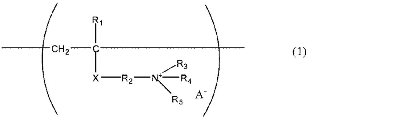
式(1)中、R1は水素原子またはメチル基を示し、R2は炭素数1乃至4のアルキレン基を示す。R3、R4およびR5から選ばれる一つまたは二つ以上は炭素数4乃至18のアルキル基を示し、残りの基は炭素数1乃至3のアルキル基を示す。Xは-COO-、-CONH-または-C6H4-のいずれかである。A-はアニオンを示す。
本発明の現像剤担持体の基体表面に形成された樹脂層は結着樹脂として熱硬化性樹脂を含有している。熱硬化性樹脂を結着樹脂とすることで、樹脂層の耐久性・環境安定性が向上する。熱硬化性樹脂としては、特に、強靭性・耐久性の面から、フェノール樹脂、メラミン樹脂、尿素樹脂、ベンゾグアナミン樹脂が好ましい。中でも、樹脂層の耐摩耗性を向上させる点、環境安定性に優れる点、後述する(C)成分との相溶性に優れることからフェノール樹脂がより好ましい。また、これら熱硬化性樹脂の中でも、特にメタノール、エタノール、プロピルアルコール、ブタノールのような低級アルコールに可溶なものは、(C)成分との相溶性が特に良好なために好ましい。
本発明の現像剤担持体の基体表面に形成された樹脂層は、前記式(1)で示されるユニットを少なくとも含有する樹脂を含む。式(1)で示されるユニットを含有する樹脂を含むことにより、当該樹脂層のトナーに対する摩擦帯電付与能を向上させることができる。また、式(1)で示されるユニットがイオン導電性を有しているため、従来の荷電制御剤に比べて樹脂層の導電性が向上し、トナーに対する過剰な摩擦帯電を抑制できる。
(a)R1がメチル基、R2がメチレン基またはエチレン基であり、
(b)R3、R4およびR5から選ばれる一つまたは二つ以上が、オクチル基、ノニル基、デシル基、ウンデシル基、ドデシル基、トリデシル基およびテトラデシル基からなる群から選ばれる何れかであり、
(c)R3、R4およびR5のうちでオクチル基、ノニル基、デシル基、ウンデシル基、ドデシル基、トリデシル基およびテトラデシル基でない基は、メチル基、エチル基およびプロピル基から選ばれる何れかであり、かつ、
(d)A-が硫黄原子またはハロゲン原子を含むアニオンであるもの。
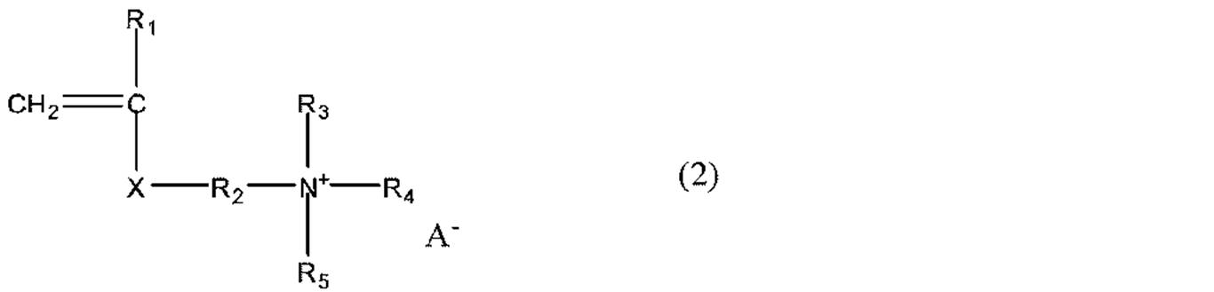
式(2)中の、R1乃至R5XおよびA-の定義は、前記式(1)のものと同じである。

式(3)中の、R1乃至R4、Xの定義は前記式(1)のものと同じである。
・アルキルハライド(ブチルブロマイド、2-エチルヘキシルブロマイド、オクチルブロマイド、ラウリルブロマイド、ステアリルブロマイド、ブチルクロライド、2-エチルヘキシルクロライド、オクチルクロライド、ラウリルクロライド、ステアリルクロライド等)。
・有機酸化合物(p-トルエンスルホン酸メチル、ジメチル硫酸、ヒドロキシナフタレンスルホン酸メチル等)。
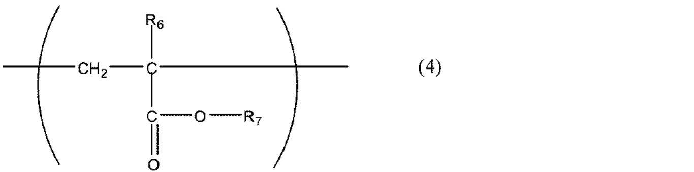
式(4)中の、R6は水素原子またはメチル基を示し、R7は炭素数8乃至18のアルキル基を示す。
上記の課題は、導電剤として黒鉛化カーボンブラックと酸性カーボンブラックを併用することで解決し得ることを本発明者らは見出した。すなわち、黒鉛化カーボンブラックは黒鉛化過程で官能基が除去され、電気的に中性である。そのため、黒鉛化カーボンブラック同士は凝集しやすい傾向がある。しかし、樹脂層形成用の塗料を調製の際に、黒鉛化カーボンブラックを酸性カーボンブラックとともに分散させると、黒鉛化カーボンブラックの凝集物が徐々にほぐされ、黒鉛化カーボンブラックが均一に分散された塗料を得ることができる。また、かかる塗料を用いることで、黒鉛化カーボンブラックが均一に分散された樹脂層を備えた現像剤担持体を得ることができる。樹脂層形成用の塗料の調製の際に、黒鉛化カーボンブラックを酸性カーボンブラックとともに分散させると黒鉛化カーボンブラックが均一に分散された塗料を得られる理由は以下のように考えられる。一般に、pHが5.0以下の酸性カーボンブラック同士は、斥力が作用し、アルコール系樹脂溶液中への分散性が非常に良好であることが知られている。すなわち、塗料中には均一に分散している。また、酸性カーボンブラックは相対的に負に帯電されやすい。一方、黒鉛化カーボンブラックは、酸性カーボンブラックとの接触によって徐々に正帯電性を呈するようになる。その結果、均一分散している酸性カーボンブラックに電気的に引き付けられ、凝集がほぐされていくものと考えられる。
次に、本発明に係る現像装置について説明する。図1は、本発明の現像剤担持体を有する一実施形態の現像装置の模式断面図を示す。図1において、公知のプロセスにより形成された静電潜像を保持する静電潜像担持体、例えば、電子写真感光ドラム501は、矢印B方向に回転される。現像剤担持体としての現像スリーブ508は、現像剤を収容している現像剤容器としてのホッパー503によって供給された、磁性トナーを有する一成分系現像剤504を担持して矢印A方向に回転する。それによって、現像スリーブ508と感光ドラム501とが対向している現像領域Dに現像剤504を搬送する。図1に示すように、現像スリーブ508内には、現像剤504を現像スリーブ508上に磁気的に吸引且つ保持するために、磁石が内接されているマグネットローラー505が配置されている。
現像剤担持体表面の算術平均粗さ(Ra)の測定は、JIS B0601(2001)の表面粗さに基づき、小坂研究所製サーフコーダーSE-3500を用い、測定条件としてはカットオフ0.8mm、評価長さ8mm、送り速度0.5mm/sにて実施した。測定位置は、現像剤担持体の中央位置と、その中央位置と塗工両端部との中間の位置の計3箇所、更に120°現像剤担持体を回転した後同様に3箇所、更に120°現像剤担持体を回転した後同様に3箇所、計9点について各々測定し、その平均値をとった。
添加樹脂のポリマーの構造は、熱分解GC/MS装置「Voyager」(商品名、サーモエレクトロン社製)で分析して求めた。なお、本分析は、熱分解温度:600℃、カラム:HP-1(15m×0.25mm×0.25μm)、Inlet:300℃、Split:20.0、注入量:1.2ml/min、昇温:50℃(4min)-300℃(20℃/min)の条件で行った。
黒鉛化カーボンブラック粉末を測定試料とし、試料水平型強力X線回折装置「RINT/TTR-II」(商品名、リガク社製)を用い、X線回折スペクトルから求めた。
先ず測定試料を無反射試料板に充填し、モノクロメーターにより単色化したCuKα線を線源とし、X線回折チャートを得た。これより黒鉛(002)回折線のピーク位置を求め、ブラッグの公式(下記式(1))より面間隔を計算したものである。ここでCuKα線の波長λは、0.15418nmとした。
面間隔(002)=λ/2sinθ 式(1)
以下に主な測定条件を記す。
光学系 :平行ビーム光学系
ゴニオメータ :ローター水平型ゴニオメータ(TTR-2)
管電圧/電流 :50kV/300mA
測定法 :連続法
スキャン軸 :2θ/θ
測定角度 :10°~50°
サンプリング間隔:0.02°
スキャン速度 :4°/min
発散スリット :開放
発散縦スリット :10mm
散乱スリット :開放
受光スリット :1.00mm
JIS K5101(1991)に準拠して、煮沸法により抽出した溶液を、pHメーターで測定した。用いたpHメーターは測定方式がガラス電極法の装置であり、pH測定範囲は0乃至14(分解能0.01)であり、測定温度は20℃乃至25℃とした。
本発明における平均円形度は、粒子の形状を定量的に表現する簡便な方法として用いたものである。本発明では東亞医用電子製フロー式粒子像分析装置「FPIA-1000」を用いて測定を行い、3μm以上の円相当径の粒子群について測定された各粒子の円形度(Ci)を下式によりそれぞれ求めた。また、平均円形度は各粒子の円形度を相加平均した値とする。
円形度(Ci)=(粒子像と同じ投影面積を持つ円の周囲長)/(粒子の投影像の周囲長)
測定装置である「FPIA-1000」は、各粒子の円形度を算出後、平均円形度およびモード円形度の算出に当たり、次のような方法を用いている。粒子を得られた円形度によって、円形度0.40~1.00を0.010間隔で61分割したクラスに分け、分割点の中心値と頻度を用いて平均円形度の算出を行う方法である。しかしながら、この算出法で算出される平均円形度の各値と、上述した各粒子の円形度を直接用いる算出式によって算出される平均円形度の各値との誤差は、非常に少なく、実質的には無視出来る程度のものである。よって、本発明においては、算出時間の短絡化や算出演算式の簡略化のようなデータの取り扱い上の理由で、上述した各粒子の円形度を直接用いる算出式の概念を利用し、一部変更したこのような算出法を用いている。本発明における平均円形度とは、粒子の凹凸度合いの指標であり、粒子が完全な球形の場合1.000を示し、トナーの表面形状が複雑になるほど平均円形度は小さな値となる。
撹拌機、冷却器、温度計、窒素導入管および滴下ロートを付した4つ口セパラブルフラスコ内で、以下の材料を混合し、系が均一になるまで攪拌した。
・ジメチルアミノエチルメタクリレート 36.5部
・ラウリルブロマイド(4級化剤) 63.5部
・エタノール 50部
撹拌を続けながら、70℃まで昇温した後5時間攪拌してモノマーの4級化を行い、4級アンモニウム塩基含有モノマーである、(2-メタクリロイロキシエチル)ラウリルジメチルアンモニウムブロマイドを得た。得られた反応溶液を冷却した後、溶媒としてエタノール50部、および重合開始剤としてアゾビスイソブチロニトリル(AIBN)1.0部を滴下ロートに仕込み、系が均一になるまで撹拌した。撹拌を続けながら、反応系内の温度が70℃になるまで昇温し、滴下ロートに仕込んだ上記重合開始剤を含有するエタノール溶液を1時間かけて添加した。滴下終了後、窒素導入下還流状態で更に5時間反応させ、さらにAIBNを0.2部添加した後1時間反応させた。更に、この溶液をエタノールで希釈して固形分40%の添加樹脂溶液B-1を得た。得られた添加樹脂溶液B-1の構造を表2に示す。
使用する成分を表1に示した成分にした以外は、添加樹脂溶液B-1の製造例と同様にして、添加樹脂溶液B-2~B-15を得た。尚、添加樹脂溶液B-11に関しては、溶液生成後、イオン交換樹脂によりアニオンを臭素イオンからp-トルエンスルホン酸イオンへのイオン交換を行った。得られた添加樹脂溶液B-2~B-15の構造を表2に示す。
撹拌機、冷却器、温度計、窒素導入管および滴下ロートを付した4つ口セパラブルフラスコ内で、以下の材料を混合し、系が均一になるまで攪拌した。
・ジメチルアミノエチルメタクリレート 36.5部
・ラウリルブロマイド(4級化剤) 63.5部
・エタノール 50部
撹拌を続けながら、70℃まで昇温した後5時間攪拌してモノマーの4級化を行い、4級アンモニウム塩基含有モノマーである、(2-メタクリロイロキシエチル)ラウリルジメチルアンモニウムブロマイドを得た。得られた反応溶液を冷却した後、共重合成分として、オクチルアクリレート5.2部、溶媒としてエタノール50部、および重合開始剤としてアゾビスイソブチロニトリル(AIBN)1.0部を滴下ロートに仕込み、系が均一になるまで撹拌した。撹拌を続けながら、反応系内の温度が70℃になるまで昇温し、上記滴下ロートに仕込んだ溶液を1時間かけて添加した。滴下終了後、窒素導入下還流状態で更に5時間反応させ、さらにAIBNを0.2部添加した後1時間反応させた。更に、この溶液をエタノールで希釈して固形分40%の添加樹脂溶液B-16を得た。得られた添加樹脂溶液B-16の構造を表2に示す。
使用する成分を表1に示した成分としたこと以外は、添加樹脂溶液B-1の製造例および添加樹脂溶液B-16の製造例と同様にして、添加樹脂溶液B-17~B-30を得た。得られた添加樹脂溶液B-17~B-30の構造を表2に示す。
以下使用する成分を表1に示した成分としたこと以外は、添加樹脂溶液B-1の製造例と同様にして、添加樹脂溶液b-1~b-5を得た。得られた添加樹脂溶液b-1~b-5の構造を表2に示す。
以下に実施例において使用した結着樹脂の具体例を示す。

カーボンブラック(商品名:トーカブラック#5500、東海カーボン社製)を黒鉛坩堝に入れ、窒素ガス雰囲気中2500℃で熱処理して黒鉛化を行い、黒鉛化カーボンブラックG-1を得た。得られた黒鉛化カーボンブラックの物性値を表3に示す。
黒鉛化カーボンブラックG-1の製造例と同様の方法で、粒径の異なるカーボンブラックを黒鉛化処理して、本発明にて使用することのできる黒鉛化カーボンブラックG-2~G-7を製造した。黒鉛化処理は、カーボンブラックを黒鉛坩堝に充填し、窒素ガス雰囲気中、1000℃~3000℃で、熱処理することで黒鉛化処理をした。得られた黒鉛化カーボンブラックの物性値を表3に示す。
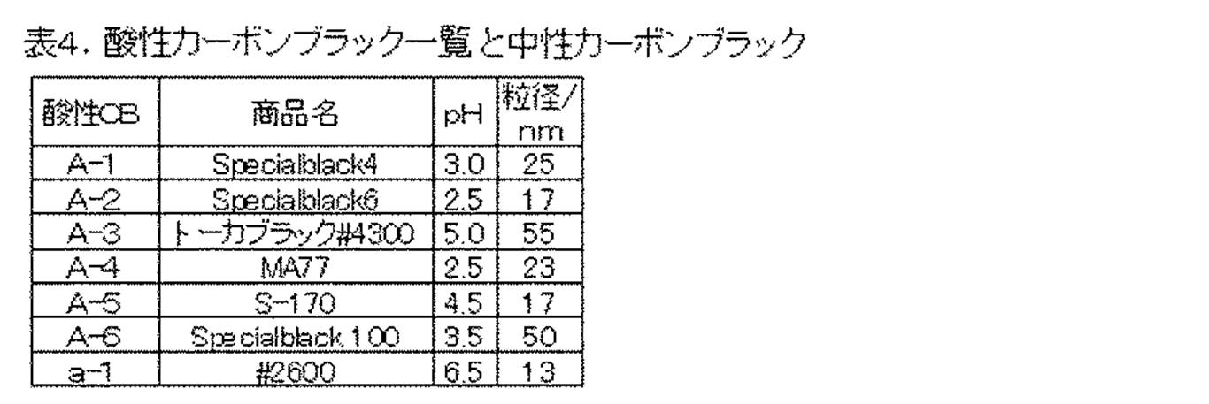
本実施例で用いた酸性カーボンブラックA-1~A-6および中性カーボンブラックa-1を表4に示す。
スチレン73.5部、アクリル酸n-ブチル19部、マレイン酸モノブチル7部、ジビニルベンゼン0.5部、ベンゾイルパーオキサイド1部およびジ-t-ブチルパーオキシ-2-エチルヘキサノエート0.5部の混合物を用意した。この混合物に対し、ポリビニルアルコール部分ケン化物0.8部を溶解した水180部を加え、激しく攪拌させて懸濁分散液とした。この懸濁分散液を、水40部を入れて窒素置換した反応器に入れ、反応温度85℃にて10時間懸濁重合した。反応終了後、ろ過、水洗し、脱水、乾燥工程を経て、ビニル系樹脂を得た。
・上記のビニル系樹脂: 100部
・平均粒径が0.2μmの球状磁性体: 90部
・アゾ系鉄錯体化合物
(負帯電性荷電制御剤、保土谷化学工業社製、商品名:T-77):1部
・ステアリン酸ステアリルワックス(DSCのメインピーク60℃):5部
この混合物を130℃に加熱した2軸混練押し出し機にて混練した。得られた混練物を冷却した後、ハンマーミルで粗粉砕し得られた粗粉砕物を、機械式粉砕機ターボミル(ターボ工業社製)を用いて微粉砕を行なった後、熱球形化処理を行なった。熱球形化処理を行った微粉砕粉を、コアンダ効果を利用した多分割分級装置(エルボジェット分級機、日鉄鉱業社製)で、超微粉および粗粉を同時に分級除去して、重量平均粒径(D4)6.0μm、円形度が0.963であるトナー粒子を得た。このトナー粒子100部に疎水性コロイダルシリカ1.0部を添加し、ヘンシェルミキサーにて混合分散させることで、磁性一成分トナー1を得た。
温度60℃に加温したイオン交換水900部に、リン酸三カルシウム4部を添加し、これをTK式ホモミキサー(特殊機化工業製)により10,000rpmにて撹拌し、水系媒体を作製した。
一方、下記の組成物をTK式ホモミキサー(特殊機化工業製)に投入し、温度60℃に加温した後、9,000rpmにて攪拌して溶解、分散した。
・スチレン 160部
・n-ブチルアクリレート 40部
・C.I.ピグメントレッド2 16部
・サリチル酸アルミニウム化合物(ボントロンE-88:オリエント化学社製) 2部
・ポリエステル樹脂(プロピレンオキサイド変性ビスフェノールAとイソフタル酸との重縮合物、Tg=65℃、Mw=10000、Mn=6000) 7部
・ステアリン酸ステアリルワックス(DSCのメインピーク60℃) 20部
・ジビニルベンゼン 0.2部
これに、重合開始剤t-ブチルパーオキシピバレート20部を溶解し、重合性単量体系組成物を調製した。調製した重合性単量体組成物を、前記水系媒体中に投入し、温度60℃,窒素雰囲気下において、TK式ホモミキサーを用いて9,000rpmで攪拌して懸濁させた。その後、プロペラ式攪拌装置に移して攪拌しつつ、3時間かけて温度70℃に昇温し、更に4時間後、昇温速度40℃/hrで温度80℃まで昇温し、温度80℃で5時間反応を行い、重合体粒子を製造した。重合反応終了後、該粒子を含むスラリーを冷却し、スラリーの10倍量の水で洗浄、ろ過の後、6.67×10-1kPaの圧力下、温度40℃で48時間乾燥し、更に分級して粒子径を調整したマゼンタトナー粒子を得た。
<塗料中間体の作製>
以下の材料を混合し、直径1mmのガラスビーズをメディア粒子として用いたサンドミルにて2時間分散して塗料中間体を得た。
・結着樹脂1 固形分として20部
・黒鉛化カーボンブラックG-1 10部
・酸性カーボンブラックA-1 10部
・エタノール
50部
次に、塗料中間体に、以下の材料を混合し、直径1.5mmのガラスビーズをメディア粒子としたサンドミルにて40分分散して樹脂層用塗料を得た。
・結着樹脂1 固形分として 20部
・樹脂B-1 固形分として 4部
・ニカビーズICB-1020(商品名;日本カーボン社製)
2部
次いで、この樹脂層用塗料にエタノールを添加することで固形分濃度を35%に調整した。外径20mmφのアルミニウム製の円筒管を回転台に立てて回転させ、両端部にマスキングを施し、エアスプレーガンを一定速度で下降させながら、樹脂層用塗料を円筒管表面に塗工した。この工程により樹脂層を形成させた。なお、塗工条件は30℃/35%RHの環境下にて、樹脂層用塗料の温度は恒温槽で28℃に制御した状態で塗工を実施した。続いて熱風乾燥炉により150℃で30分間加熱して樹脂層を硬化させ、Ra=1.35μmである現像剤担持体S-1を作製した。表5に該現像剤担持体(現像スリーブ)S-1の樹脂層の処方を挙げた。
現像剤担持体S-1にマグネットローラを挿入した後フランジを取り付けて、デジタル複合機iR2030(商品名;キヤノン社製)の現像器に組み込み、現像装置とした。前記磁性一成分トナー1を用い、1枚/15秒の間欠モードで印字比率が1%の文字パターンにて15万枚の画像出力を行い、以下の項目(1)~(4)について評価した。結果は表6に示したように、いずれの環境下でも終始良好な現像性を得ることができた。
温度30℃/湿度85%RH(以降、「H/H」環境ともいう)の環境下で画像出力試験を行い、初期にベタ画像を出力し、その濃度を測定した。また、摩擦帯電の立ち上がりを評価すべく、15万枚を通紙した後に10日間放置し、ベタ画像を出力し、その濃度を測定することにより評価した。画像濃度は「マクベス反射濃度計 RD918」(商品名、マクベス社製)を用いて、原稿濃度が0.00の白地部分の画像に対する相対濃度を測定した。
温度15℃、湿度10%RH(以降、「L/L」環境ともいう)の環境下で画像出力試験を行い、ハーフトーンとベタ黒画像を出力し、トナーの過剰帯電により発生しやすいブロッチ(斑点状、さざ波状もしくは絨毯状)の発生を下記基準にて評価した。
A:ハーフトーン画像にもスリーブ上にも確認できない。
B:スリーブ上には確認されるが、画像には影響が出ていない。
C:ハーフトーン画像の一部に確認されるものの、ベタ黒画像では確認できない。
D:ハーフトーン画像およびベタ黒画像上で確認できる。
L/L環境およびH/H環境の下で画像出力試験を行い、スリーブ周期のゴーストについて評価を行った。プリンタの出力画像において、画像先端の現像剤担持体一周分に相当する領域を白地にベタ黒の正方形(一辺20mm)画像を等間隔で配置し、それ以外の部分をハーフトーンとしたものを用いた。そして、ハーフトーン上に正方形画像のゴーストがどのように出現するかによりランク付けを行った。
A:見る角度によって観測できる程度で、濃淡差がほぼ確認できない。
B:濃淡差が観測できるが、画像上問題ないレベル。
C:ゴーストが目視で明確に確認されるが、実用できる下限のレベル。
D:ゴーストがはっきり濃淡として現れ、反射濃度計で濃度差が測定可能。
H/H環境下で画像出力試験後の現像剤担持体の表面をレーザー顕微鏡(商品名:VK-8700、KEYENCE社製)を用いて、約1000倍で観察し、トナー汚染の程度を下記の基準にて評価した。
A:軽微な汚染しか観察されない。
B:やや汚染が観察される。
C:部分的に汚染が観察される。
D:著しい汚染が観察される。
表5に挙げた処方にて実施例1と同様に、現像スリーブS-2~S-74を作製し、評価を行った。樹脂層用塗料の固形分濃度は、適宜調節して作製した。結果を表6に記す。上記の結果から分かるように、樹脂層中に本発明の添加樹脂を加えることで、高温高湿下のような苛酷な環境においても、良好な画像濃度が得られた。画像濃度はトナーの摩擦帯電量に比例しており、4級アンモニウム塩基に長鎖アルキル基を導入することにより、良好な評価結果を得ることができた。すなわち、式(1)に示したR3、R4、R5のうち少なくとも一つを炭素数4以上にすることで、良好な画像濃度および他の画像評価においてCランク以上を達成できた。一方で、長鎖アルキル基の炭素数が18を超えた場合は、トナーへの摩擦帯電付与能は高くなるものの、熱硬化性樹脂との相溶性が相対的に低下し、L/Lでのゴーストやブロッチの評価が低かった。
<塗料中間体の作製>
以下の材料を混合し、直径1mmのガラスビーズをメディア粒子として用いたサンドミルにて2時間分散して塗料中間体を得た。
・結着樹脂1 固形分として20質量部
・黒鉛化カーボンブラックG-1 8質量部
・酸性カーボンブラックA-1 8質量部
・エタノール
50質量部
次に、塗料中間体に、以下の材料を混合し、直径1.5mmのガラスビーズをメディア粒子としたサンドミルにて40分分散して樹脂層用塗料を得た。
・結着樹脂1 固形分として 20質量部
・樹脂B-1 固形分として 4質量部
次いで、この樹脂層用塗料にエタノールを添加することで固形分濃度を33%に調整した。外径12mmφ、算術平均粗さRa=0.2μmのアルミニウム製の円筒管を回転台に立てて回転させ、両端部にマスキングを施し、エアスプレーガンを一定速度で下降させながら、樹脂層用塗料を円筒管表面に塗工した。この工程により樹脂層を形成させた。なお、塗工条件は30℃/35%RHの環境下にて、樹脂層用塗料の温度は恒温槽で28℃に制御した状態で塗工を実施した。続いて熱風乾燥炉により150℃で30分間加熱して樹脂層を硬化させ、Ra=0.50μmである現像剤担持体S-75を作製した。表7に該現像剤担持体(現像スリーブ)S-75の樹脂層の処方を挙げた。
現像剤担持体S-75をレーザービームプリンタ(商品名:LaserJet5000、ヒューレット・パッカード社製)のマゼンタカートリッジに組み込んだ。前記非磁性一成分トナー2を用い、1枚/10秒の間欠モードで印字比率が1%の文字パターンにて6000枚の画像出力を行い、以下の項目(5)~(8)について評価した。結果は表8に示したように、いずれの環境下でも終始良好な現像性を得ることができた。
低温低湿度環境(温度15℃/湿度10%RH:L/L)にて、ベタ白画像を20枚連続で出力した後にハーフトーンを出力し、濃度ムラ(モヤ状の濃淡差や画像形成進行方向に走る帯状の濃淡差)の発生を目視によって観察した。
A:ハーフトーン画像に濃淡差が全く確認できない。
B:ハーフトーン画像上に濃淡差が僅かに確認される。
C:ハーフトーン画像上の一部に濃淡差がやや確認される。
D:ハーフトーン画像上に濃淡差がはっきりと確認される。
上記ハーフトーン評価後にベタ黒画像を出力し、その濃度を測定することにより評価した。画像濃度は「マクベス反射濃度計 RD918」(マクベス社製)を用いて、原稿濃度が0.00の白地部分の画像に対する相対濃度を測定した。
温度32℃/湿度85%RHの環境下にて、6000枚印字後のベタ黒画像の濃度を測定することにより評価した。画像濃度は「マクベス反射濃度計 RD918」(マクベス社製)を用いて、原稿濃度が0.00の白地部分の画像に対する相対濃度を測定した。
「REFLECTMETER MODEL TC-6DS」(東京電色社製)により、プリントアウト画像の白地部分の白色度と転写紙の白色度を測定し、両者の白色度の差から、カブリ濃度(%)を算出した。フィルターはアンバーライトフィルターを用いた。
表7に挙げた処方にて実施例62と同様に、現像スリーブS-76~S-83を作製し、評価した。樹脂層用塗料の固形分濃度は適宜調節して作製した。結果を表8に記す。



502 トナー層厚規制部材(磁性ブレード)
503 ホッパー
504 トナー
505 マグネットローラー
506 金属製円筒管(基体)
507、517 樹脂層
508 現像剤担持体(現像スリーブ)
509 電源
510 攪拌翼
511 トナー層厚規制部材(弾性ブレード)
512 剥ぎ取り部材
513 現像スリーブとマグネットローラーの間隙
514 中実の金属棒
Claims (3)
- 基体と、該基体表面に形成された樹脂層を有する現像剤担持体において、該樹脂層は以下の(A)乃至(E)を含む塗料組成物を熱硬化して得られるものであることを特徴とする現像剤担持体:
(A)結着樹脂としての熱硬化性樹脂
(B)溶媒としての炭素数1乃至4のアルコール
(C)下記式(1)で示されるユニットを有する樹脂
(D)X線回折で測定される黒鉛(002)面の面間隔が0.3370nm以上0.3450nm以下である黒鉛化カーボンブラック
(E)pH5.0以下の酸性カーボンブラック
- R1がメチル基であり、R2がメチレン基またはエチレン基であり、R3、R4およびR5から選ばれる一つまたは二つ以上が、オクチル基、ノニル基、デシル基、ウンデシル基、ドデシル基、トリデシル基およびテトラデシル基からなる群から選ばれるいずれかであり、
R3、R4およびR5のうちでオクチル基、ノニル基、デシル基、ウンデシル基、ドデシル基、トリデシル基およびテトラデシル基でない基は、メチル基、エチル基およびプロピル基から選ばれる何れかであり、
A-が硫黄原子またはハロゲン原子を含むアニオンである請求項1に記載の現像剤担持体。 - トナー粒子を有する現像剤と、該現像剤を収容している容器と、該容器に収容された該現像剤を担持し、搬送するための現像剤担持体とを有している現像装置であって、該現像剤担持体は請求項1に記載の現像剤担持体であることを特徴とする現像装置。
Priority Applications (4)
| Application Number | Priority Date | Filing Date | Title |
|---|---|---|---|
| EP11771723.1A EP2562603B1 (en) | 2010-04-23 | 2011-04-12 | Developer carrier and developing device using the same |
| CN201180020466.2A CN102844717B (zh) | 2010-04-23 | 2011-04-12 | 显影剂承载构件和使用其的显影设备 |
| KR1020127029935A KR101384946B1 (ko) | 2010-04-23 | 2011-04-12 | 현상제 담지체, 그것을 사용한 현상 장치 |
| US13/182,753 US8377549B2 (en) | 2010-04-23 | 2011-07-14 | Developer carrying member, and developing apparatus using same |
Applications Claiming Priority (2)
| Application Number | Priority Date | Filing Date | Title |
|---|---|---|---|
| JP2010-099887 | 2010-04-23 | ||
| JP2010099887 | 2010-04-23 |
Related Child Applications (1)
| Application Number | Title | Priority Date | Filing Date |
|---|---|---|---|
| US13/182,753 Continuation US8377549B2 (en) | 2010-04-23 | 2011-07-14 | Developer carrying member, and developing apparatus using same |
Publications (1)
| Publication Number | Publication Date |
|---|---|
| WO2011132380A1 true WO2011132380A1 (ja) | 2011-10-27 |
Family
ID=44833924
Family Applications (1)
| Application Number | Title | Priority Date | Filing Date |
|---|---|---|---|
| PCT/JP2011/002153 Ceased WO2011132380A1 (ja) | 2010-04-23 | 2011-04-12 | 現像剤担持体、それを用いた現像装置 |
Country Status (6)
| Country | Link |
|---|---|
| US (1) | US8377549B2 (ja) |
| EP (1) | EP2562603B1 (ja) |
| JP (1) | JP4818476B1 (ja) |
| KR (1) | KR101384946B1 (ja) |
| CN (1) | CN102844717B (ja) |
| WO (1) | WO2011132380A1 (ja) |
Cited By (1)
| Publication number | Priority date | Publication date | Assignee | Title |
|---|---|---|---|---|
| CN114292354A (zh) * | 2021-11-01 | 2022-04-08 | 深圳市森若新材科技有限公司 | 一种可应用于空调蓄冷的聚合物相变材料 |
Families Citing this family (11)
| Publication number | Priority date | Publication date | Assignee | Title |
|---|---|---|---|---|
| JP5748619B2 (ja) * | 2011-09-06 | 2015-07-15 | キヤノン株式会社 | 現像剤担持体 |
| WO2013065303A1 (ja) | 2011-10-31 | 2013-05-10 | キヤノン株式会社 | 現像剤担持体及びその製造方法、並びに現像装置 |
| WO2013065244A1 (ja) | 2011-10-31 | 2013-05-10 | キヤノン株式会社 | 現像剤担持体及びその製造方法、並びに現像装置 |
| JP6512971B2 (ja) | 2015-07-09 | 2019-05-15 | キヤノン株式会社 | 電子写真用部材、現像装置及び画像形成装置 |
| JP6635740B2 (ja) * | 2015-09-30 | 2020-01-29 | キヤノン株式会社 | 現像装置、プロセスカートリッジおよび画像形成装置 |
| US10162281B2 (en) * | 2016-06-27 | 2018-12-25 | Canon Kabushiki Kaisha | Liquid developer and manufacturing method of liquid developer |
| JP6866112B2 (ja) * | 2016-10-31 | 2021-04-28 | キヤノン株式会社 | 現像剤担持体及び現像装置 |
| JP6463534B1 (ja) | 2017-09-11 | 2019-02-06 | キヤノン株式会社 | 現像剤担持体、プロセスカートリッジおよび電子写真装置 |
| JP7199881B2 (ja) | 2018-08-31 | 2023-01-06 | キヤノン株式会社 | 現像ローラ、電子写真プロセスカートリッジおよび電子写真用画像形成装置 |
| EP3936942A4 (en) * | 2019-03-08 | 2022-12-28 | Canon Kabushiki Kaisha | DEVELOPER SUPPORTING BODY, PROCESS CARTRIDGE AND ELECTROPHOTOGRAPHIC IMAGE FORMING DEVICE |
| CN113773673A (zh) * | 2021-10-25 | 2021-12-10 | 江西威尔士科技发展有限公司 | 炭黑石墨化改性方法 |
Citations (8)
| Publication number | Priority date | Publication date | Assignee | Title |
|---|---|---|---|---|
| JPH0830088A (ja) | 1994-07-15 | 1996-02-02 | Ricoh Co Ltd | トナー担持体及び現像装置 |
| JP2001312136A (ja) | 2000-04-28 | 2001-11-09 | Ricoh Co Ltd | トナー担持体及びその製造方法 |
| JP2006084726A (ja) * | 2004-09-15 | 2006-03-30 | Fuji Xerox Co Ltd | 導電性ロールおよびこれを備えた画像形成装置 |
| JP2006119538A (ja) * | 2004-10-25 | 2006-05-11 | Canon Inc | 現像剤担持体及び現像方法 |
| JP2007025593A (ja) | 2005-07-21 | 2007-02-01 | Canon Inc | 現像剤担持体および現像装置 |
| JP2007147734A (ja) * | 2005-11-24 | 2007-06-14 | Canon Inc | 現像方法及び現像剤担持体 |
| JP2007206647A (ja) * | 2006-02-06 | 2007-08-16 | Canon Inc | 電子写真現像方法、これに用いる現像剤担持体、これを用いたプロセスカートリッジ及び電子写真装置 |
| JP2008281697A (ja) * | 2007-05-09 | 2008-11-20 | Canon Inc | 現像装置およびそれを用いた画像形成装置 |
Family Cites Families (6)
| Publication number | Priority date | Publication date | Assignee | Title |
|---|---|---|---|---|
| EP0869404B1 (en) * | 1997-03-31 | 2000-07-12 | Canon Kabushiki Kaisha | Developer carrying member comprising a resin coat layer wherein a binder resin of a molecular weight of from 3,000 to 50,000 comprises a copolymer having a methyl methacrylate monomer and a nitrogen containing vinyl monomer |
| JP2005215268A (ja) * | 2004-01-29 | 2005-08-11 | Fuji Xerox Co Ltd | 画像形成装置および画像形成方法 |
| CN101164019B (zh) * | 2005-06-15 | 2010-12-01 | 佳能化成株式会社 | 正电荷控制树脂、显影辊和电子照相设备 |
| KR101188078B1 (ko) * | 2005-07-21 | 2012-10-08 | 캐논 가부시끼가이샤 | 현상제 담지체 및 현상 장치 |
| JP5247616B2 (ja) * | 2008-07-29 | 2013-07-24 | キヤノン株式会社 | 現像剤担持体及びその製造方法、現像装置及び現像方法 |
| US8182405B2 (en) * | 2008-09-30 | 2012-05-22 | Canon Kabushiki Kaisha | Developing roller, developing roller production method, process cartridge, and electrophotographic apparatus |
-
2011
- 2011-04-08 JP JP2011086273A patent/JP4818476B1/ja not_active Expired - Fee Related
- 2011-04-12 EP EP11771723.1A patent/EP2562603B1/en not_active Not-in-force
- 2011-04-12 CN CN201180020466.2A patent/CN102844717B/zh not_active Expired - Fee Related
- 2011-04-12 KR KR1020127029935A patent/KR101384946B1/ko not_active Expired - Fee Related
- 2011-04-12 WO PCT/JP2011/002153 patent/WO2011132380A1/ja not_active Ceased
- 2011-07-14 US US13/182,753 patent/US8377549B2/en not_active Expired - Fee Related
Patent Citations (8)
| Publication number | Priority date | Publication date | Assignee | Title |
|---|---|---|---|---|
| JPH0830088A (ja) | 1994-07-15 | 1996-02-02 | Ricoh Co Ltd | トナー担持体及び現像装置 |
| JP2001312136A (ja) | 2000-04-28 | 2001-11-09 | Ricoh Co Ltd | トナー担持体及びその製造方法 |
| JP2006084726A (ja) * | 2004-09-15 | 2006-03-30 | Fuji Xerox Co Ltd | 導電性ロールおよびこれを備えた画像形成装置 |
| JP2006119538A (ja) * | 2004-10-25 | 2006-05-11 | Canon Inc | 現像剤担持体及び現像方法 |
| JP2007025593A (ja) | 2005-07-21 | 2007-02-01 | Canon Inc | 現像剤担持体および現像装置 |
| JP2007147734A (ja) * | 2005-11-24 | 2007-06-14 | Canon Inc | 現像方法及び現像剤担持体 |
| JP2007206647A (ja) * | 2006-02-06 | 2007-08-16 | Canon Inc | 電子写真現像方法、これに用いる現像剤担持体、これを用いたプロセスカートリッジ及び電子写真装置 |
| JP2008281697A (ja) * | 2007-05-09 | 2008-11-20 | Canon Inc | 現像装置およびそれを用いた画像形成装置 |
Non-Patent Citations (1)
| Title |
|---|
| See also references of EP2562603A4 * |
Cited By (1)
| Publication number | Priority date | Publication date | Assignee | Title |
|---|---|---|---|---|
| CN114292354A (zh) * | 2021-11-01 | 2022-04-08 | 深圳市森若新材科技有限公司 | 一种可应用于空调蓄冷的聚合物相变材料 |
Also Published As
| Publication number | Publication date |
|---|---|
| EP2562603A1 (en) | 2013-02-27 |
| KR101384946B1 (ko) | 2014-04-11 |
| KR20130029399A (ko) | 2013-03-22 |
| US20110274467A1 (en) | 2011-11-10 |
| CN102844717A (zh) | 2012-12-26 |
| CN102844717B (zh) | 2014-12-03 |
| JP4818476B1 (ja) | 2011-11-16 |
| JP2011242758A (ja) | 2011-12-01 |
| EP2562603B1 (en) | 2016-07-27 |
| EP2562603A4 (en) | 2016-01-20 |
| US8377549B2 (en) | 2013-02-19 |
Similar Documents
| Publication | Publication Date | Title |
|---|---|---|
| JP4818476B1 (ja) | 現像剤担持体、それを用いた現像装置 | |
| JP5247616B2 (ja) | 現像剤担持体及びその製造方法、現像装置及び現像方法 | |
| JP4494518B1 (ja) | 現像剤担持体及び現像装置 | |
| JP5094595B2 (ja) | 現像剤担持体及び現像装置 | |
| JP4448174B2 (ja) | 現像剤担持体及び現像装置 | |
| JP2006030456A (ja) | 現像方法及び該現像方法に用いられる現像剤担持体 | |
| JP5464974B2 (ja) | 現像装置 | |
| JP3332727B2 (ja) | 画像形成方法及びトナー | |
| JP5464994B2 (ja) | 画像形成方法 | |
| JP4280604B2 (ja) | 現像剤担持体及びそれを用いた現像装置 | |
| JP2005157270A (ja) | 現像剤担持体及び現像装置 | |
| JP3060155B2 (ja) | 画像形成方法 | |
| JP4250485B2 (ja) | 現像剤担持体 | |
| JP4794933B2 (ja) | 現像剤担持体および現像装置 | |
| JP5173122B2 (ja) | 現像剤担持体および現像装置 | |
| JP2007108467A (ja) | 現像剤担持体及び現像装置 | |
| JPH1090996A (ja) | 現像剤担持体及びこれを用いた現像装置 | |
| JP2002072668A (ja) | 現像剤担持体及び現像装置 | |
| JP5523176B2 (ja) | 現像剤担持体 | |
| JP2002072666A (ja) | 現像剤担持体、現像装置及びプロセスカートリッジ | |
| JPH04149452A (ja) | 静電潜像現像用現像剤及び画像形成方法 |
Legal Events
| Date | Code | Title | Description |
|---|---|---|---|
| WWE | Wipo information: entry into national phase |
Ref document number: 201180020466.2 Country of ref document: CN |
|
| 121 | Ep: the epo has been informed by wipo that ep was designated in this application |
Ref document number: 11771723 Country of ref document: EP Kind code of ref document: A1 |
|
| REEP | Request for entry into the european phase |
Ref document number: 2011771723 Country of ref document: EP |
|
| WWE | Wipo information: entry into national phase |
Ref document number: 2011771723 Country of ref document: EP |
|
| NENP | Non-entry into the national phase |
Ref country code: DE |
|
| ENP | Entry into the national phase |
Ref document number: 20127029935 Country of ref document: KR Kind code of ref document: A |