WO2011142121A1 - 交流電気車 - Google Patents
交流電気車 Download PDFInfo
- Publication number
- WO2011142121A1 WO2011142121A1 PCT/JP2011/002598 JP2011002598W WO2011142121A1 WO 2011142121 A1 WO2011142121 A1 WO 2011142121A1 JP 2011002598 W JP2011002598 W JP 2011002598W WO 2011142121 A1 WO2011142121 A1 WO 2011142121A1
- Authority
- WO
- WIPO (PCT)
- Prior art keywords
- power
- converter
- link
- electric vehicle
- opening
- Prior art date
- Legal status (The legal status is an assumption and is not a legal conclusion. Google has not performed a legal analysis and makes no representation as to the accuracy of the status listed.)
- Ceased
Links
Images


Classifications
-
- B—PERFORMING OPERATIONS; TRANSPORTING
- B60—VEHICLES IN GENERAL
- B60L—PROPULSION OF ELECTRICALLY-PROPELLED VEHICLES; SUPPLYING ELECTRIC POWER FOR AUXILIARY EQUIPMENT OF ELECTRICALLY-PROPELLED VEHICLES; ELECTRODYNAMIC BRAKE SYSTEMS FOR VEHICLES IN GENERAL; MAGNETIC SUSPENSION OR LEVITATION FOR VEHICLES; MONITORING OPERATING VARIABLES OF ELECTRICALLY-PROPELLED VEHICLES; ELECTRIC SAFETY DEVICES FOR ELECTRICALLY-PROPELLED VEHICLES
- B60L9/00—Electric propulsion with power supply external to the vehicle
- B60L9/16—Electric propulsion with power supply external to the vehicle using AC induction motors
- B60L9/24—Electric propulsion with power supply external to the vehicle using AC induction motors fed from AC supply lines
-
- B—PERFORMING OPERATIONS; TRANSPORTING
- B60—VEHICLES IN GENERAL
- B60L—PROPULSION OF ELECTRICALLY-PROPELLED VEHICLES; SUPPLYING ELECTRIC POWER FOR AUXILIARY EQUIPMENT OF ELECTRICALLY-PROPELLED VEHICLES; ELECTRODYNAMIC BRAKE SYSTEMS FOR VEHICLES IN GENERAL; MAGNETIC SUSPENSION OR LEVITATION FOR VEHICLES; MONITORING OPERATING VARIABLES OF ELECTRICALLY-PROPELLED VEHICLES; ELECTRIC SAFETY DEVICES FOR ELECTRICALLY-PROPELLED VEHICLES
- B60L1/00—Supplying electric power to auxiliary equipment of vehicles
-
- B—PERFORMING OPERATIONS; TRANSPORTING
- B60—VEHICLES IN GENERAL
- B60L—PROPULSION OF ELECTRICALLY-PROPELLED VEHICLES; SUPPLYING ELECTRIC POWER FOR AUXILIARY EQUIPMENT OF ELECTRICALLY-PROPELLED VEHICLES; ELECTRODYNAMIC BRAKE SYSTEMS FOR VEHICLES IN GENERAL; MAGNETIC SUSPENSION OR LEVITATION FOR VEHICLES; MONITORING OPERATING VARIABLES OF ELECTRICALLY-PROPELLED VEHICLES; ELECTRIC SAFETY DEVICES FOR ELECTRICALLY-PROPELLED VEHICLES
- B60L3/00—Electric devices on electrically-propelled vehicles for safety purposes; Monitoring operating variables, e.g. speed, deceleration or energy consumption
- B60L3/0023—Detecting, eliminating, remedying or compensating for drive train abnormalities, e.g. failures within the drive train
-
- B—PERFORMING OPERATIONS; TRANSPORTING
- B60—VEHICLES IN GENERAL
- B60L—PROPULSION OF ELECTRICALLY-PROPELLED VEHICLES; SUPPLYING ELECTRIC POWER FOR AUXILIARY EQUIPMENT OF ELECTRICALLY-PROPELLED VEHICLES; ELECTRODYNAMIC BRAKE SYSTEMS FOR VEHICLES IN GENERAL; MAGNETIC SUSPENSION OR LEVITATION FOR VEHICLES; MONITORING OPERATING VARIABLES OF ELECTRICALLY-PROPELLED VEHICLES; ELECTRIC SAFETY DEVICES FOR ELECTRICALLY-PROPELLED VEHICLES
- B60L50/00—Electric propulsion with power supplied within the vehicle
- B60L50/50—Electric propulsion with power supplied within the vehicle using propulsion power supplied by batteries or fuel cells
- B60L50/51—Electric propulsion with power supplied within the vehicle using propulsion power supplied by batteries or fuel cells characterised by AC-motors
-
- B—PERFORMING OPERATIONS; TRANSPORTING
- B60—VEHICLES IN GENERAL
- B60L—PROPULSION OF ELECTRICALLY-PROPELLED VEHICLES; SUPPLYING ELECTRIC POWER FOR AUXILIARY EQUIPMENT OF ELECTRICALLY-PROPELLED VEHICLES; ELECTRODYNAMIC BRAKE SYSTEMS FOR VEHICLES IN GENERAL; MAGNETIC SUSPENSION OR LEVITATION FOR VEHICLES; MONITORING OPERATING VARIABLES OF ELECTRICALLY-PROPELLED VEHICLES; ELECTRIC SAFETY DEVICES FOR ELECTRICALLY-PROPELLED VEHICLES
- B60L50/00—Electric propulsion with power supplied within the vehicle
- B60L50/50—Electric propulsion with power supplied within the vehicle using propulsion power supplied by batteries or fuel cells
- B60L50/53—Electric propulsion with power supplied within the vehicle using propulsion power supplied by batteries or fuel cells in combination with an external power supply, e.g. from overhead contact lines
-
- B—PERFORMING OPERATIONS; TRANSPORTING
- B60—VEHICLES IN GENERAL
- B60L—PROPULSION OF ELECTRICALLY-PROPELLED VEHICLES; SUPPLYING ELECTRIC POWER FOR AUXILIARY EQUIPMENT OF ELECTRICALLY-PROPELLED VEHICLES; ELECTRODYNAMIC BRAKE SYSTEMS FOR VEHICLES IN GENERAL; MAGNETIC SUSPENSION OR LEVITATION FOR VEHICLES; MONITORING OPERATING VARIABLES OF ELECTRICALLY-PROPELLED VEHICLES; ELECTRIC SAFETY DEVICES FOR ELECTRICALLY-PROPELLED VEHICLES
- B60L7/00—Electrodynamic brake systems for vehicles in general
- B60L7/10—Dynamic electric regenerative braking
- B60L7/14—Dynamic electric regenerative braking for vehicles propelled by AC motors
-
- B—PERFORMING OPERATIONS; TRANSPORTING
- B60—VEHICLES IN GENERAL
- B60L—PROPULSION OF ELECTRICALLY-PROPELLED VEHICLES; SUPPLYING ELECTRIC POWER FOR AUXILIARY EQUIPMENT OF ELECTRICALLY-PROPELLED VEHICLES; ELECTRODYNAMIC BRAKE SYSTEMS FOR VEHICLES IN GENERAL; MAGNETIC SUSPENSION OR LEVITATION FOR VEHICLES; MONITORING OPERATING VARIABLES OF ELECTRICALLY-PROPELLED VEHICLES; ELECTRIC SAFETY DEVICES FOR ELECTRICALLY-PROPELLED VEHICLES
- B60L7/00—Electrodynamic brake systems for vehicles in general
- B60L7/10—Dynamic electric regenerative braking
- B60L7/16—Dynamic electric regenerative braking for vehicles comprising converters between the power source and the motor
-
- H—ELECTRICITY
- H02—GENERATION; CONVERSION OR DISTRIBUTION OF ELECTRIC POWER
- H02J—ELECTRIC POWER NETWORKS; CIRCUIT ARRANGEMENTS OR SYSTEMS FOR SUPPLYING OR DISTRIBUTING ELECTRIC POWER; SYSTEMS FOR STORING ELECTRIC ENERGY
- H02J7/00—Circuit arrangements for charging or discharging batteries or for supplying loads from batteries
- H02J7/34—Parallel operation in networks using both storage and other DC sources, e.g. providing buffering
-
- B—PERFORMING OPERATIONS; TRANSPORTING
- B60—VEHICLES IN GENERAL
- B60L—PROPULSION OF ELECTRICALLY-PROPELLED VEHICLES; SUPPLYING ELECTRIC POWER FOR AUXILIARY EQUIPMENT OF ELECTRICALLY-PROPELLED VEHICLES; ELECTRODYNAMIC BRAKE SYSTEMS FOR VEHICLES IN GENERAL; MAGNETIC SUSPENSION OR LEVITATION FOR VEHICLES; MONITORING OPERATING VARIABLES OF ELECTRICALLY-PROPELLED VEHICLES; ELECTRIC SAFETY DEVICES FOR ELECTRICALLY-PROPELLED VEHICLES
- B60L2200/00—Type of vehicles
- B60L2200/26—Rail vehicles
-
- B—PERFORMING OPERATIONS; TRANSPORTING
- B60—VEHICLES IN GENERAL
- B60L—PROPULSION OF ELECTRICALLY-PROPELLED VEHICLES; SUPPLYING ELECTRIC POWER FOR AUXILIARY EQUIPMENT OF ELECTRICALLY-PROPELLED VEHICLES; ELECTRODYNAMIC BRAKE SYSTEMS FOR VEHICLES IN GENERAL; MAGNETIC SUSPENSION OR LEVITATION FOR VEHICLES; MONITORING OPERATING VARIABLES OF ELECTRICALLY-PROPELLED VEHICLES; ELECTRIC SAFETY DEVICES FOR ELECTRICALLY-PROPELLED VEHICLES
- B60L2210/00—Converter types
- B60L2210/10—DC to DC converters
-
- B—PERFORMING OPERATIONS; TRANSPORTING
- B60—VEHICLES IN GENERAL
- B60L—PROPULSION OF ELECTRICALLY-PROPELLED VEHICLES; SUPPLYING ELECTRIC POWER FOR AUXILIARY EQUIPMENT OF ELECTRICALLY-PROPELLED VEHICLES; ELECTRODYNAMIC BRAKE SYSTEMS FOR VEHICLES IN GENERAL; MAGNETIC SUSPENSION OR LEVITATION FOR VEHICLES; MONITORING OPERATING VARIABLES OF ELECTRICALLY-PROPELLED VEHICLES; ELECTRIC SAFETY DEVICES FOR ELECTRICALLY-PROPELLED VEHICLES
- B60L2210/00—Converter types
- B60L2210/30—AC to DC converters
-
- B—PERFORMING OPERATIONS; TRANSPORTING
- B60—VEHICLES IN GENERAL
- B60L—PROPULSION OF ELECTRICALLY-PROPELLED VEHICLES; SUPPLYING ELECTRIC POWER FOR AUXILIARY EQUIPMENT OF ELECTRICALLY-PROPELLED VEHICLES; ELECTRODYNAMIC BRAKE SYSTEMS FOR VEHICLES IN GENERAL; MAGNETIC SUSPENSION OR LEVITATION FOR VEHICLES; MONITORING OPERATING VARIABLES OF ELECTRICALLY-PROPELLED VEHICLES; ELECTRIC SAFETY DEVICES FOR ELECTRICALLY-PROPELLED VEHICLES
- B60L2210/00—Converter types
- B60L2210/40—DC to AC converters
-
- B—PERFORMING OPERATIONS; TRANSPORTING
- B60—VEHICLES IN GENERAL
- B60Y—INDEXING SCHEME RELATING TO ASPECTS CROSS-CUTTING VEHICLE TECHNOLOGY
- B60Y2200/00—Type of vehicle
- B60Y2200/30—Railway vehicles
-
- B—PERFORMING OPERATIONS; TRANSPORTING
- B60—VEHICLES IN GENERAL
- B60Y—INDEXING SCHEME RELATING TO ASPECTS CROSS-CUTTING VEHICLE TECHNOLOGY
- B60Y2200/00—Type of vehicle
- B60Y2200/30—Railway vehicles
- B60Y2200/31—Locomotives
-
- B—PERFORMING OPERATIONS; TRANSPORTING
- B60—VEHICLES IN GENERAL
- B60Y—INDEXING SCHEME RELATING TO ASPECTS CROSS-CUTTING VEHICLE TECHNOLOGY
- B60Y2200/00—Type of vehicle
- B60Y2200/90—Vehicles comprising electric prime movers
- B60Y2200/91—Electric vehicles
- B60Y2200/912—Electric vehicles with power supply external to vehicle, e.g. trolley buses or trams
-
- H—ELECTRICITY
- H02—GENERATION; CONVERSION OR DISTRIBUTION OF ELECTRIC POWER
- H02M—APPARATUS FOR CONVERSION BETWEEN AC AND AC, BETWEEN AC AND DC, OR BETWEEN DC AND DC, AND FOR USE WITH MAINS OR SIMILAR POWER SUPPLY SYSTEMS; CONVERSION OF DC OR AC INPUT POWER INTO SURGE OUTPUT POWER; CONTROL OR REGULATION THEREOF
- H02M5/00—Conversion of AC power input into AC power output, e.g. for change of voltage, for change of frequency, for change of number of phases
- H02M5/40—Conversion of AC power input into AC power output, e.g. for change of voltage, for change of frequency, for change of number of phases with intermediate conversion into DC
- H02M5/42—Conversion of AC power input into AC power output, e.g. for change of voltage, for change of frequency, for change of number of phases with intermediate conversion into DC by static converters
- H02M5/44—Conversion of AC power input into AC power output, e.g. for change of voltage, for change of frequency, for change of number of phases with intermediate conversion into DC by static converters using discharge tubes or semiconductor devices to convert the intermediate DC into AC
- H02M5/453—Conversion of AC power input into AC power output, e.g. for change of voltage, for change of frequency, for change of number of phases with intermediate conversion into DC by static converters using discharge tubes or semiconductor devices to convert the intermediate DC into AC using devices of a triode or transistor type requiring continuous application of a control signal
- H02M5/458—Conversion of AC power input into AC power output, e.g. for change of voltage, for change of frequency, for change of number of phases with intermediate conversion into DC by static converters using discharge tubes or semiconductor devices to convert the intermediate DC into AC using devices of a triode or transistor type requiring continuous application of a control signal using semiconductor devices only
- H02M5/4585—Conversion of AC power input into AC power output, e.g. for change of voltage, for change of frequency, for change of number of phases with intermediate conversion into DC by static converters using discharge tubes or semiconductor devices to convert the intermediate DC into AC using devices of a triode or transistor type requiring continuous application of a control signal using semiconductor devices only having a rectifier with controlled elements
-
- Y—GENERAL TAGGING OF NEW TECHNOLOGICAL DEVELOPMENTS; GENERAL TAGGING OF CROSS-SECTIONAL TECHNOLOGIES SPANNING OVER SEVERAL SECTIONS OF THE IPC; TECHNICAL SUBJECTS COVERED BY FORMER USPC CROSS-REFERENCE ART COLLECTIONS [XRACs] AND DIGESTS
- Y02—TECHNOLOGIES OR APPLICATIONS FOR MITIGATION OR ADAPTATION AGAINST CLIMATE CHANGE
- Y02T—CLIMATE CHANGE MITIGATION TECHNOLOGIES RELATED TO TRANSPORTATION
- Y02T10/00—Road transport of goods or passengers
- Y02T10/60—Other road transportation technologies with climate change mitigation effect
- Y02T10/70—Energy storage systems for electromobility, e.g. batteries
-
- Y—GENERAL TAGGING OF NEW TECHNOLOGICAL DEVELOPMENTS; GENERAL TAGGING OF CROSS-SECTIONAL TECHNOLOGIES SPANNING OVER SEVERAL SECTIONS OF THE IPC; TECHNICAL SUBJECTS COVERED BY FORMER USPC CROSS-REFERENCE ART COLLECTIONS [XRACs] AND DIGESTS
- Y02—TECHNOLOGIES OR APPLICATIONS FOR MITIGATION OR ADAPTATION AGAINST CLIMATE CHANGE
- Y02T—CLIMATE CHANGE MITIGATION TECHNOLOGIES RELATED TO TRANSPORTATION
- Y02T10/00—Road transport of goods or passengers
- Y02T10/60—Other road transportation technologies with climate change mitigation effect
- Y02T10/72—Electric energy management in electromobility
Definitions
- the present invention relates to an AC electric vehicle that runs on AC power.
- an AC electric vehicle is provided with a three-winding main transformer.
- AC power from an overhead line (so-called feeder, more precisely an overhead train line) is fed to the primary side of the main transformer.
- a secondary circuit for supplying electric power to a main motor for running an AC electric vehicle is connected to the secondary side of the main transformer.
- a tertiary circuit for supplying power to auxiliary equipment such as air conditioners and lighting is connected to the tertiary side of the main transformer.
- the secondary circuit may be provided with a battery in order to operate the main motor efficiently.
- the tertiary circuit may be provided with a battery in order to continuously supply power even when power supply from the overhead line is stopped.
- Patent Literature 1 Japanese published patent gazettes and Japanese Unexamined Patent Publication No. 2009-95080 (hereinafter referred to as Patent Literature 1).
- the secondary circuit and the tertiary circuit are insulated from each other. For this reason, even if a battery is provided in one of the secondary circuit and the tertiary circuit, this battery cannot be used in the other circuit. Thus, power cannot be shared between the secondary circuit and the tertiary circuit between these circuits.
- an object of the present invention is to provide an AC electric vehicle that can use electric power between a circuit for supplying electric power to an electric motor for running the vehicle and a circuit for supplying electric power to an auxiliary device. It is to provide.
- An AC electric vehicle has the following configuration. That is, An electric motor for driving the vehicle; A first converter that converts AC power supplied from a train line into DC power; A first inverter that converts the DC power converted by the first converter into AC power and supplies the AC power to the motor; A first DC link for connecting the respective DC sides of the first converter and the first inverter to each other; First charging means for charging DC power supplied from the first DC link; First opening / closing means for electrically connecting and disconnecting the first DC link and the first charging means; A load other than the aforementioned motor, and A second converter for converting AC power supplied from the aforementioned train line into DC power; A second inverter that converts the DC power converted by the second converter into AC power and supplies the AC power to the load; A second DC link for connecting the DC sides of the second converter and the second inverter to each other; A DC / DC converter that converts the DC power supplied from the first DC link into a DC voltage suitable for the second DC link, and supplies the DC voltage to the second
- the alternating current electric vehicle which can share electric power between the circuit for supplying electric power to the electric motor for driving a vehicle and the circuit for supplying electric power to auxiliary equipment is provided. be able to.
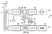
- FIG. 1 is a configuration diagram showing the configuration of an AC electric vehicle 1 according to a first embodiment of the present invention.
- symbol is attached
- the AC electric vehicle 1 includes a current collector 2, a circuit breaker 3, a main transformer 4, a secondary circuit C2, a tertiary circuit C3, a battery 8a, a DC / DC converter 9, and contactors 11a and 11b. And a manual switch 12.
- the current collector 2 collects AC power fed from the overhead line 31.
- the current collector 2 supplies the collected AC power to the primary side of the main transformer 4 via the circuit breaker 3.
- the upper system side of the circuit breaker 3 is connected to the current collector 2.
- the lower system side of the circuit breaker 3 is connected to the main transformer 4.
- the circuit breaker 3 When the circuit breaker 3 is turned on, it electrically connects the overhead wire 31 and the electric circuit in the AC electric vehicle 1. When opened, the circuit breaker 3 electrically disconnects the overhead wire 31 and the electric circuit in the AC electric vehicle 1.
- the main transformer 4 is connected to the circuit breaker 3 on the primary side.
- the main transformer 4 has a secondary circuit C2 connected to the secondary side.
- the main transformer 4 has a tertiary circuit C3 connected to the tertiary side.
- the main transformer 4 steps down and supplies the AC power supplied from the overhead line 31 to the secondary circuit C2 and the tertiary circuit C3 during powering.
- the main transformer 4 returns the AC power supplied from the secondary circuit C2 to the overhead line 31 during regeneration.
- the secondary circuit C2 includes a converter 5a, an inverter 6a, a main motor 7, and a filter capacitor 13a.
- the AC side of the converter 5a is connected to the secondary side of the main transformer 4.
- the DC side of the converter 5a is connected to the DC side of the inverter 6a by an intermediate DC link LN2.
- Converter 5a converts AC power supplied from main transformer 4 to DC power and supplies it to inverter 6a during powering.
- Converter 5a converts the DC power supplied from inverter 6a into AC power and supplies it to main transformer 4 during regeneration.
- the DC side of the inverter 6a is connected to the converter 5a.
- the AC side of the inverter 6 a is connected to the main motor 7.
- inverter 6a converts the DC power supplied from converter 5a into AC power and supplies it to main motor 7.
- the inverter 6a converts the regenerative power from the main motor 7 into DC power and supplies it to the converter 5a.
- the inverter 6a is, for example, a VVVF (variable voltage variable frequency) inverter.
- the main motor 7 is a power source for running the AC electric vehicle 1 during power running.
- the main motor 7 is driven by AC power supplied from the inverter 6a.
- the main motor 7 is a power source that generates regenerative power during regeneration.
- the main motor 7 supplies the generated regenerative power to the inverter 6a.
- the filter capacitor 13a is provided between the positive electrode and the negative electrode of the intermediate DC link LN2.
- the filter capacitor 13a has one terminal connected to the positive electrode of the intermediate DC link LN2 and the other terminal connected to the negative electrode.
- the filter capacitor 13a reduces the current ripple that flows through the intermediate DC link LN2.
- the tertiary circuit C3 includes a converter 5b, an inverter 6b, an auxiliary device 10, a filter capacitor 13b, and a contactor 14b.
- the AC side of the converter 5b is connected to the tertiary side of the main transformer 4.
- the DC side of the converter 5b is connected to the DC side of the inverter 6b by an intermediate DC link LN3.
- Converter 5b converts the AC power supplied from main transformer 4 into DC power and supplies it to inverter 6b.
- the DC side of the inverter 6b is connected to the converter 5b.
- the AC side of the inverter 6 b is connected to the auxiliary device 10.
- the inverter 6b converts the DC power supplied from the converter 5b into AC power and supplies the AC power to the auxiliary device 10.
- the inverter 6b is, for example, a CVCF (constant voltage constant frequency) constant inverter.
- the auxiliary device 10 is a device that becomes a load other than the main motor 7.
- the auxiliary device 10 is, for example, an auxiliary device when the AC electric vehicle 1 is operated such as an air conditioner, electric vehicle lighting, or a power source of a control circuit.
- the filter capacitor 13b is provided between the positive electrode and the negative electrode of the intermediate DC link LN3.
- the filter capacitor 13b has one terminal connected to the positive electrode of the intermediate DC link LN3 and the other terminal connected to the negative electrode.
- the filter capacitor 13b reduces the current ripple that flows through the intermediate DC link LN3.
- the contactor 14b is provided in the intermediate DC link LN3. When the contactor 14b is turned on, it electrically connects the converter 5b and the inverter 6b. When opened, contactor 14b electrically disconnects converter 5b and inverter 6b.
- the battery 8a is connected to the intermediate DC link LN2 of the secondary circuit C2 through the contactor 11a.
- the battery 8a is connected to the intermediate DC link LN3 of the tertiary circuit C3 through the contactor 11b and the DC / DC converter 9 in order.
- contactor 11a When the contactor 11a is turned on, it electrically connects the battery 8a and the intermediate DC link LN2. When opened, contactor 11a electrically disconnects battery 8a and intermediate DC link LN2.
- the contactor 11b When the contactor 11b is turned on, it electrically connects the battery 8a and the intermediate DC link LN3 (or DC / DC converter 9). When opened, the contactor 11b electrically disconnects the battery 8a and the intermediate DC link LN3 (or DC / DC converter 9).
- the DC / DC converter 9 converts the DC power supplied from the contactor 11b into a DC voltage suitable for the intermediate DC link LN3 of the tertiary circuit C3.
- the DC / DC converter 9 supplies the converted DC power to the intermediate DC link LN3.
- the manual switch 12 is an operating device for individually turning on or off each of the contactors 11a and 11b by an operator (driver or conductor).
- the manual switch 12 is installed in a driver's cab or equipment room.
- the contactor 11a When the AC electric vehicle 1 is powering or regenerating, the contactor 11a is turned on and the contactor 11b is turned off. During power running, the battery 8a is charged with power from the overhead line 31. During regeneration, the battery 8a is charged with regenerative power from the main motor 7.
- the operator When giving top priority to moving the AC electric vehicle 1 to a place where power can be obtained from the overhead line (train line) 31, the operator turns on the contactor 11a and turns off the contactor 11b. Thereby, the battery 8a supplies electric power only to the secondary circuit C2.
- the operator turns off the contactor 11a and turns on the contactor 11b.
- the battery 8a supplies electric power only to the tertiary circuit C3 via the DC / DC converter 9.
- the operator When moving the AC electric vehicle 1 while operating the auxiliary device 10, the operator turns on both the contactors 11a and 11b. Thereby, the battery 8a supplies electric power to both the secondary circuit C2 and the tertiary circuit C3.
- the operator can arbitrarily select the power supply destination circuits C2 and C3 of the battery 8a by operating the contactors 11a and 11b.
- the operator can prioritize the power supply to the main motor 7 by selecting the circuit C2 as the power supply destination of the battery 8a (turning on the contactor 11a). Thereby, AC electric vehicle 1 can give priority to moving to the place where electric power feeding is obtained.
- Priority can be given to continuing the operation of the auxiliary device 10 when the operator selects the circuit C3 as the power supply destination of the battery 8a (turns on the contactor 11b).
- the auxiliary device 10 is a service device such as a lighting or an air conditioner in a cabin vehicle
- priority can be given to continuation of service to passengers.
- the case where the operator selects the circuit C3 is a case where the power supply from the overhead line (train line) 31 can be expected to return in a short time.
- the operator selects both the circuit C2 and the circuit C3 as the power supply destination of the battery 8a (both the contactors 11a and 11b are turned on), so that the operation of the auxiliary device 10 such as the service device is continued, and the AC electric vehicle 1 can move to a place where power can be obtained.
- the operator can select an optimum method for sharing the charged energy of the battery 8a to the secondary circuit C2 and the tertiary circuit C3 of the AC electric vehicle 1 according to the situation.
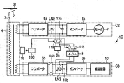
- FIG. 2 is a block diagram showing the configuration of an AC electric vehicle 1A according to the second embodiment of the present invention.
- AC electric vehicle 1A has a configuration in which vehicle control device 13 is provided in place of manual switch 12 in AC electric vehicle 1 according to the first embodiment shown in FIG. The other points are the same as in the first embodiment.
- the contactor 11a When the AC electric vehicle 1A is in powering, the contactor 11a is turned on and the contactor 11b is turned off. During power running, the battery 8a is charged with electric power from the overhead line (train line) 31.
- the vehicle control device 13 outputs a regeneration command signal for causing the inverter 6a to perform a regenerative operation.
- the regeneration command signal output from the vehicle control device 13 is output as a command to the inverter 6a and is a signal for turning on both the contactors 11a and 11b. Thereby, when it becomes at the time of regeneration, the regenerative electric power generated from the main motor 7 charges the battery 8a. This regenerative power is also supplied to the tertiary circuit C3 via the DC / DC converter 9.
- the contactors 11a and 11b are automatically turned on by the regenerative command signal output from the vehicle control device 13. Thereby, at the time of regenerative operation of AC electric vehicle 1A, regenerated electric power can be used effectively by secondary circuit C2 and tertiary circuit C3.
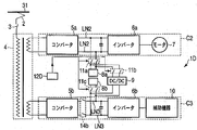
- FIG. 3 is a block diagram showing the configuration of an AC electric vehicle 1B according to the third embodiment of the present invention.
- AC electric vehicle 1B has a configuration in which DC voltage monitoring device 15b is added to AC electric vehicle 1A according to the second embodiment shown in FIG. 2 and converter 5b1 is provided instead of converter 5b.
- the other points are the same as in the second embodiment.
- the contactor 11a When the AC electric vehicle 1B is in powering, the contactor 11a is turned on and the contactor 11b is turned off. During power running, the battery 8a is charged with electric power from the overhead line (train line) 31. When AC electric vehicle 1 ⁇ / b> B is in regeneration, both contactors 11 a and 11 b are turned on by vehicle control device 13. At the time of regeneration, the regenerative power from the main motor 7 is charged in the battery 8a and is also supplied to the tertiary circuit C3.
- the DC voltage monitoring device 15b is provided in the intermediate DC link LN3 of the tertiary circuit C3.
- the DC voltage monitoring device 15b monitors the DC voltage of the intermediate DC link LN3.
- the DC voltage monitoring device 15b detects that the DC voltage of the intermediate DC link LN3 has decreased, the DC voltage monitoring device 15b transmits a detection signal to the converter 5b1.
- converter 5b1 When converter 5b1 receives a detection signal indicating that the DC voltage of intermediate DC link LN3 has dropped from DC voltage monitoring device 15b while power is supplied from overhead line (train line) 31, converter 5b1 turns off contactor 11a. Then, the contactor 11b is turned on. Thereby, the battery 8a supplies electric power only to the tertiary circuit C3 via the DC / DC converter 9.
- the converter 5b1 is the same as the converter 5b according to the first embodiment.
- the converter 5b1 when the converter 5b1 receives power from the overhead line (train line) 31 and receives a detection signal indicating a voltage drop from the DC voltage monitoring device 15b, the converter 5b1 has a failure or the like. Means that.
- the AC electric vehicle 1B can detect the failure of the converter 5b1. By this detection, the contactors 11a and 11b are operated so as to supply power from the battery 8a to the tertiary circuit C3. Thereby, unstable operation and operation stop of the auxiliary device 10 of the tertiary circuit C3 can be avoided.
- FIG. 4 is a block diagram showing the configuration of an AC electric vehicle 1C according to the fourth embodiment of the present invention.
- the AC electric vehicle 1 ⁇ / b> C has a configuration in which a section detection vehicle upper 16 is added to the AC electric vehicle 1 ⁇ / b> A according to the second embodiment shown in FIG. 2 and a vehicle control device 13 ⁇ / b> C is provided instead of the vehicle control device 13. is there.
- the other points are the same as in the second embodiment.
- the contactor 11a When the AC electric vehicle 1C is in powering or regeneration, the contactor 11a is turned on and the contactor 11b is turned off. During power running, the battery 8a is charged with electric power from the overhead line (train line) 31. During regeneration, the battery 8a is charged with regenerative power from the main motor 7.
- the section detection vehicle upper 16 detects in advance that it enters the non-electric section before entering the non-electric section (dead section).
- the non-electric section is a section where power is not supplied from the overhead line (train line) 31.
- the section detection vehicle upper arm 16 When detecting that the section detection vehicle upper arm 16 enters the non-electric section, the section detection vehicle upper arm 16 outputs a dead section passage signal to the vehicle control device 13C.
- the vehicle control device 13C When the vehicle control device 13C receives a dead section passage signal from the section detection vehicle upper member 16, the vehicle control device 13C turns on the contactor 11b. At this time, the contactor 11a may be turned on simultaneously. Thereby, the battery 8a supplies electric power to the tertiary circuit C3 via the DC / DC converter 9.
- the AC electric vehicle 1C can detect entry into the non-electric section before actually entering the non-electric section. Thereby, AC electric vehicle 1C can prepare for power supply from battery 8a to tertiary circuit C3 before entering the non-electric section. Therefore, the AC electric vehicle 1 ⁇ / b> C can continue the operation of the auxiliary device 10 without causing an instantaneous stop even when passing through the non-electric section.
- the auxiliary device 10 is a service device such as a lighting or an air conditioner in a passenger vehicle
- the AC electric vehicle 1C can pass through the non-electric section while continuing the service to the passengers.
- FIG. 5 is a block diagram showing the configuration of an AC electric vehicle 1D according to the fifth embodiment of the present invention.
- AC electric vehicle 1D has a configuration in which battery 8b and contactor 11c are added to manual electric switch 12D instead of manual switch 12 in AC electric vehicle 1 according to the first embodiment shown in FIG.
- the other points are the same as in the first embodiment.
- the battery 8b is connected to the intermediate DC link LN3 of the tertiary circuit C3 and the output side of the DC / DC converter 9 via the contactor 11c. That is, the battery 8 b is connected to the battery 8 a via the DC / DC converter 9.
- the contactor 11c When the contactor 11c is inserted, the battery 8b and the intermediate DC link LN3 are electrically connected. Further, the battery 8b and the output side of the DC / DC converter 9 are electrically connected. When the contactor 11c is opened, the battery 8b is electrically disconnected from the intermediate DC link LN3 and the output side of the DC / DC converter 9.
- the manual switch 12D is an operating device for individually turning on or off each of the contactors 11a and 11b11c by an operator (driver or conductor).
- the manual switch 12D is installed in a driver's cab or equipment room.
- the contactors 11a and 11c are turned on and the contactor 11b is turned off.
- the battery 8a charges and discharges the secondary circuit C2.
- the battery 8b charges and discharges the tertiary circuit C3.
- the operator When giving top priority to moving the AC electric vehicle 1 to a place where power can be obtained from the overhead line (train line) 31, the operator turns on the contactor 11a and turns off the contactor 11b. Thereby, the battery 8a supplies electric power only to the secondary circuit C2.
- the operator turns off the contactor 11a and turns on the contactor 11b.
- the battery 8a supplies electric power only to the tertiary circuit C3 via the DC / DC converter 9.
- the operator When moving the AC electric vehicle 1 while operating the auxiliary device 10, the operator turns on both the contactors 11a and 11b. Thereby, the battery 8a supplies electric power to both the secondary circuit C2 and the tertiary circuit C3.
- the contactor 11c When the contactor 11c is turned on and the contactor 11b is turned on, the power supplied from the battery 8a to the tertiary circuit C3 is reduced. When the contactor 11c is turned on and the contactor 11b is turned off, the battery 8b can continue to supply power to the tertiary circuit C3.
- the operator turns off the contactor 11c, whereby the power supplied from the battery 8a to the tertiary circuit C3 is charged into the battery 8b. To prevent it.
- the power supply to the tertiary circuit C3 can be continued more reliably even when power is not supplied from the overhead line (train line) 31. Further, it is possible to reduce the burden of power supply from the battery 8a to the tertiary circuit C3.
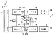
- FIG. 6 is a block diagram showing the configuration of an AC electric vehicle 1E according to the sixth embodiment of the present invention.
- the AC electric vehicle 1E is the same as the AC electric vehicle 1D according to the fifth embodiment shown in FIG. 5, except that the vehicle control device 13E is provided instead of the manual switch 12D, and the converter 5b2 is provided instead of the converter 5b. is there. Other points are the same as in the fifth embodiment.
- the contactors 11a and 11c are turned on and the contactor 11b is turned off.
- the battery 8a charges and discharges the secondary circuit C2.
- the battery 8b charges and discharges the tertiary circuit C3.
- the vehicle control device 13E When the vehicle control device 13E detects a failure of the converter 5b2, the vehicle control device 13E turns off the contactor 11a and turns on the contactor 11b. Similarly, when converter 5b2 self-detects a failure, contactor 11a is turned off and contactor 11b is turned on. Thereby, the battery 8a supplies electric power only to the tertiary circuit C3 via the DC / DC converter 9.
- the AC electric vehicle 1E when the AC electric vehicle 1E detects a failure of the converter 5b2, the AC electric vehicle 1E automatically operates the contactors 11a and 11b so that the power supply destination of the battery 8a is only the tertiary circuit C3.
- the power supply by the battery 8b is added, whereby the power supply to the tertiary circuit C3 can be strengthened.
- the state in which the contactors 11a and 11b are automatically operated is not limited to the pattern shown in each embodiment. Whether or not the contactors 11a and 11b are automatically turned on or off can be appropriately determined depending on the environment in which the AC electric vehicle is applied, the driving situation, or the like.
- the contactors 11a and 11b are turned on by the regeneration command signal output from the vehicle control device 13, but the present invention is not limited to this.
- the inverter 6a that has received the regeneration command signal output from the vehicle control device 13 may output a signal for turning on the contactors 11a and 11b.
- the converter 5b1 is configured to self-detect a failure and operate the contactors 11a and 11b, but is not limited thereto.
- the vehicle control device 13 may detect the failure of the converter 5b1 and operate the contactors 11a and 11b. Further, the contents detected for operating the contactors 11a and 11b are not limited to the failure of the converter 5b1. Others may be used as long as the power supplied to the tertiary circuit C3 is assumed to be unstable.
- any method may be used for detecting a failure of the converters 5b1 and 5b2.
- a DC voltage monitoring device 15b may be provided to self-detect a failure.
- the present invention is not limited to the above-described embodiments as they are, and can be embodied by modifying the components without departing from the scope of the invention in the implementation stage.
- Various inventions can be formed by appropriately combining a plurality of constituent elements disclosed in the above embodiments. For example, some components may be deleted from all the components shown in the embodiments. Furthermore, constituent elements over different embodiments may be appropriately combined.
- the present invention can be applied to an AC electric vehicle that runs on AC power.
- SYMBOLS 1 AC electric vehicle, 2 ... Current collector, 3 ... Circuit breaker, 4 ... Main transformer, 5a, 5b ... Converter, 6a, 6b ... Inverter, 7 ... Main motor, 8a ... Battery, 9 ... DC / DC converter 11a, 11b ... contactor, 12 ... manual switch, 13a, 13b ... filter capacitor, 14b ... contactor, C2 ... secondary circuit, C3 ... tertiary circuit, LN2, LN3 ... intermediate DC link.
Landscapes
- Engineering & Computer Science (AREA)
- Power Engineering (AREA)
- Transportation (AREA)
- Mechanical Engineering (AREA)
- Life Sciences & Earth Sciences (AREA)
- Sustainable Development (AREA)
- Sustainable Energy (AREA)
- Electric Propulsion And Braking For Vehicles (AREA)
Abstract
Description
車両を走行させるための電動機と、
電車線から供給される交流電力を直流電力に変換する第1のコンバータと、
前述の第1のコンバータにより変換された直流電力を交流電力に変換し、前述の電動機に供給する第1のインバータと、
前述の第1のコンバータと前述の第1のインバータとのそれぞれの直流側を互いに接続するための第1の直流リンクと、
前述の第1の直流リンクから供給される直流電力を充電する第1の充電手段と、
前述の第1の直流リンクと前述の第1の充電手段との電気的な接続及び切り離しをする第1の開閉手段と、
前述の電動機以外の負荷と、
前述の電車線から供給される交流電力を直流電力に変換する第2のコンバータと、
前述の第2のコンバータにより変換された直流電力を交流電力に変換し、前述の負荷に供給する第2のインバータと、
前述の第2のコンバータと前述の第2のインバータとのそれぞれの直流側を互いに接続するための第2の直流リンクと、
前述の第1の直流リンクから供給される直流電力を前述の第2の直流リンクに適合する直流電圧に変換し、前述の第2の直流リンクに供給する直流/直流コンバータと、
前述の第1の直流リンクと前述の第2の直流リンクとを前述の直流/直流コンバータを介して電気的に接続及び切り離しをする第2の開閉手段と
を備えている。
図1は、本発明の第1の実施例に係る交流電気車1の構成を示す構成図である。なお、以降の図における同一部分には同一符号を付してその詳しい説明を省略し、異なる部分について主に述べる。以降の実施例も同様にして重複する説明を省略する。
図2は、本発明の第2の実施例に係る交流電気車1Aの構成を示す構成図である。
図3は、本発明の第3の実施例に係る交流電気車1Bの構成を示す構成図である。
図4は、本発明の第4の実施例に係る交流電気車1Cの構成を示す構成図である。
図5は、本発明の第5の実施例に係る交流電気車1Dの構成を示す構成図である。
図6は、本発明の第6の実施例に係る交流電気車1Eの構成を示す構成図である。
Claims (7)
- 車両を走行させるための電動機と、
電車線から供給される交流電力を直流電力に変換する第1のコンバータと、
前記第1のコンバータにより変換された直流電力を交流電力に変換し、前記電動機に供給する第1のインバータと、
前記第1のコンバータと前記第1のインバータとのそれぞれの直流側を互いに接続するための第1の直流リンクと、
前記第1の直流リンクから供給される直流電力を充電する第1の充電手段と、
前記第1の直流リンクと前記第1の充電手段との電気的な接続及び切り離しをする第1の開閉手段と、
前記電動機以外の負荷と、
前記電車線から供給される交流電力を直流電力に変換する第2のコンバータと、
前記第2のコンバータにより変換された直流電力を交流電力に変換し、前記負荷に供給する第2のインバータと、
前記第2のコンバータと前記第2のインバータとのそれぞれの直流側を互いに接続するための第2の直流リンクと、
前記第1の直流リンクから供給される直流電力を前記第2の直流リンクに適合する直流電圧に変換し、前記第2の直流リンクに供給する直流/直流コンバータと、
前記第1の直流リンクと前記第2の直流リンクとを前記直流/直流コンバータを介して電気的に接続及び切り離しをする第2の開閉手段と
を備えたことを特徴とする交流電気車。
- 前記第1の開閉手段を手動で操作するための第1の操作手段と、
前記第2の開閉手段を手動で操作するための第2の操作手段と
を備えたことを特徴とする請求項1に記載の交流電気車。
- 前記第2の直流リンクから供給される直流電力を充電する第2の充電手段と、
前記第2の直流リンクと前記第2の充電手段との電気的な接続及び切り離しをする第3の開閉手段と
を備えたことを特徴とする請求項1に記載の交流電気車。
- 前記第1の開閉手段を手動で操作するための第1の操作手段と、
前記第2の開閉手段を手動で操作するための第2の操作手段と、
前記第3の開閉手段を手動で操作するための第3の操作手段と
を備えたことを特徴とする請求項3に記載の交流電気車。
- 前記第1のインバータは、前記電動機から発生した回生電力を交流電力に変換して前記第1の直流リンクに供給する回生動作をし、前記第1のインバータが前記回生動作をする場合、前記第1の開閉手段及び前記第2の開閉手段を自動的に投入する回生時自動投入手段と
を備えたことを特徴とする請求項1から請求項4のいずれか1項に記載の交流電気車。
- 前記第2のコンバータの異常を検出する異常検出手段と、
前記異常検出手段により異常を検出した場合、前記第2の開閉手段を投入する異常時投入手段と
を備えたことを特徴とする請求項1から請求項5のいずれか1項に記載の交流電気車。
- 前記電車線から交流電力が供給されない無電区間への突入を事前に検知する無電区間事前検知手段と、
前記無電区間事前検知手段により前記無電区間への突入を事前に検知した場合、前記第2の開閉手段を投入する無電区間突入時投入手段と
を備えたことを特徴とする請求項1から請求項6のいずれか1項に記載の交流電気車。
Priority Applications (3)
| Application Number | Priority Date | Filing Date | Title |
|---|---|---|---|
| AU2011251493A AU2011251493B2 (en) | 2010-05-12 | 2011-05-10 | AC electric vehicle |
| CN201180018420.7A CN102985280B (zh) | 2010-05-12 | 2011-05-10 | 交流电动车辆 |
| EP11780380.9A EP2570292B1 (en) | 2010-05-12 | 2011-05-10 | Alternating-current electric vehicle |
Applications Claiming Priority (2)
| Application Number | Priority Date | Filing Date | Title |
|---|---|---|---|
| JP2010110416A JP5398634B2 (ja) | 2010-05-12 | 2010-05-12 | 交流電気車 |
| JP2010-110416 | 2010-05-12 |
Publications (1)
| Publication Number | Publication Date |
|---|---|
| WO2011142121A1 true WO2011142121A1 (ja) | 2011-11-17 |
Family
ID=44914181
Family Applications (1)
| Application Number | Title | Priority Date | Filing Date |
|---|---|---|---|
| PCT/JP2011/002598 Ceased WO2011142121A1 (ja) | 2010-05-12 | 2011-05-10 | 交流電気車 |
Country Status (5)
| Country | Link |
|---|---|
| EP (1) | EP2570292B1 (ja) |
| JP (1) | JP5398634B2 (ja) |
| CN (1) | CN102985280B (ja) |
| AU (1) | AU2011251493B2 (ja) |
| WO (1) | WO2011142121A1 (ja) |
Cited By (2)
| Publication number | Priority date | Publication date | Assignee | Title |
|---|---|---|---|---|
| EP2810813A4 (en) * | 2012-01-30 | 2015-12-16 | Mitsubishi Electric Corp | DRIVE CONTROL DEVICE FOR AN ELECTRIC VEHICLE AND CONTROL PROCESS THEREFOR |
| DE102024121425A1 (de) | 2024-07-26 | 2026-01-29 | Putzmeister Engineering Gmbh | Vorrichtung zum Fördern von Dickstoff |
Families Citing this family (29)
| Publication number | Priority date | Publication date | Assignee | Title |
|---|---|---|---|---|
| JP5995470B2 (ja) * | 2012-03-14 | 2016-09-21 | 九州旅客鉄道株式会社 | 電気車用電源システム及び電力供給制御方法 |
| JP5914068B2 (ja) * | 2012-03-14 | 2016-05-11 | 九州旅客鉄道株式会社 | 電気車用電源システム及び電力供給制御方法 |
| JP5931669B2 (ja) * | 2012-09-21 | 2016-06-08 | 九州旅客鉄道株式会社 | 電気車用電源システム及び電力供給制御方法 |
| JP5947176B2 (ja) * | 2012-09-21 | 2016-07-06 | 九州旅客鉄道株式会社 | 電気車用電源システム及び電力供給制御方法 |
| JP5972756B2 (ja) * | 2012-10-31 | 2016-08-17 | 株式会社東芝 | 電気車制御装置 |
| US10065511B2 (en) | 2013-07-02 | 2018-09-04 | Mitsubishi Electric Corporation | Hybrid drive system |
| JP6262002B2 (ja) * | 2014-02-03 | 2018-01-17 | 東芝インフラシステムズ株式会社 | 電気車制御装置 |
| EP3023291A1 (de) * | 2014-11-20 | 2016-05-25 | ABB Technology AG | Umrichtersystem zum elektrischen antreiben eines fahrzeuges |
| WO2017037795A1 (ja) * | 2015-08-28 | 2017-03-09 | 株式会社東芝 | 鉄道車両、車両用電力変換装置及び方法 |
| JP2017070169A (ja) * | 2015-10-02 | 2017-04-06 | 株式会社東芝 | 鉄道用電力変換装置 |
| JP6736369B2 (ja) * | 2016-06-16 | 2020-08-05 | 東海旅客鉄道株式会社 | 電力変換システム |
| JP6736370B2 (ja) * | 2016-06-16 | 2020-08-05 | 東海旅客鉄道株式会社 | 電力変換システム |
| JP6815762B2 (ja) * | 2016-06-17 | 2021-01-20 | 東海旅客鉄道株式会社 | 電力変換システム |
| JP6786268B2 (ja) * | 2016-06-17 | 2020-11-18 | 東海旅客鉄道株式会社 | 蓄電システム |
| KR101830625B1 (ko) * | 2016-08-16 | 2018-03-29 | 한국철도기술연구원 | 철도차량용 간이 추진 시스템 및 이의 제어방법 |
| DE102016222856A1 (de) * | 2016-11-21 | 2018-05-24 | Bombardier Transportation Gmbh | Elektrisches Netzwerk für ein Schienenfahrzeug, Schienenfahrzeug und Verfahren zum Betrieb eines elektrischen Netzwerks |
| JP6829069B2 (ja) * | 2016-12-28 | 2021-02-10 | 株式会社東芝 | 鉄道車両用回路システム |
| EP3696005A4 (en) * | 2017-10-13 | 2021-07-14 | Hitachi, Ltd. | DRIVE CONTROL DEVICE AND ADJUSTMENT STRAND ASSEMBLED WITH THIS DRIVE CONTROL DEVICE |
| CN110014864B (zh) * | 2017-12-20 | 2021-02-09 | 中车长春轨道客车股份有限公司 | 一种列车牵引救援方法及系统 |
| DE102018120736A1 (de) * | 2018-08-24 | 2020-02-27 | Deutsches Zentrum für Luft- und Raumfahrt e.V. | Verfahren zum Betreiben eines hybriden elektrischen Antriebssystems, Antriebssystem und Verwendung des Antriebssystems bei einem Luftfahrzeug |
| AT521386B1 (de) * | 2018-12-27 | 2020-01-15 | Plasser & Theurer Export Von Bahnbaumaschinen Gmbh | Schnittstellenvorrichtung für eine Gleisbaumaschine |
| CN110539668B (zh) * | 2019-01-29 | 2021-01-22 | 中车长春轨道客车股份有限公司 | 一种动车组应急牵引系统 |
| FR3093492B1 (fr) * | 2019-03-06 | 2025-03-07 | Speedinnov | Véhicule ferroviaire équipé d’un organe de stockage électrique |
| JP7301686B2 (ja) * | 2019-09-12 | 2023-07-03 | 東海旅客鉄道株式会社 | 電力変換システム |
| JP7408323B2 (ja) * | 2019-09-12 | 2024-01-05 | 東海旅客鉄道株式会社 | 電力変換システム |
| DE102019125944A1 (de) * | 2019-09-26 | 2021-04-01 | Bombardier Transportation Gmbh | Batteriegestütztes Schienenfahrzeug |
| CN112810458B (zh) * | 2019-11-15 | 2022-05-13 | 株洲中车时代电气股份有限公司 | 列车供电系统的救援电路和列车供电系统 |
| SE543966C2 (en) * | 2020-02-06 | 2021-10-12 | Scania Cv Ab | A method for propelling and manufacturing of a vehicle comprising a power train with an electric motor and a vehicle comprising a power train with an electric motor |
| DE102021203026A1 (de) * | 2021-03-26 | 2022-09-29 | Siemens Mobility GmbH | Fahrzeugtraktionssystem |
Citations (4)
| Publication number | Priority date | Publication date | Assignee | Title |
|---|---|---|---|---|
| JPH0398401A (ja) * | 1989-09-11 | 1991-04-24 | Toshiba Corp | 電気車制御装置 |
| JP2001320804A (ja) * | 2000-05-09 | 2001-11-16 | Meidensha Corp | 電源設備および電気車 |
| JP2009072003A (ja) * | 2007-09-14 | 2009-04-02 | Kawasaki Heavy Ind Ltd | 電気鉄道システム |
| JP2009095080A (ja) | 2007-10-04 | 2009-04-30 | Toshiba Corp | 交流電車の補助電源装置 |
Family Cites Families (11)
| Publication number | Priority date | Publication date | Assignee | Title |
|---|---|---|---|---|
| JPS62225197A (ja) * | 1986-03-25 | 1987-10-03 | Toshiba Corp | 電動機制御装置 |
| DE4340341A1 (de) * | 1993-11-26 | 1995-06-01 | Abb Patent Gmbh | Traktionsstromrichter für ein Schienenfahrzeug |
| DE19547465C1 (de) * | 1995-12-19 | 1996-12-19 | Siemens Ag | Stromrichteranordnung mit gekoppelten Spannungs-Zwischenkreisen |
| JP2001145201A (ja) * | 1999-11-15 | 2001-05-25 | Shizuki Electric Co Inc | 電気鉄道車両制御電源システム |
| JP3776348B2 (ja) * | 2001-12-10 | 2006-05-17 | 本田技研工業株式会社 | 車両用電源装置 |
| DE102004033379A1 (de) * | 2004-07-09 | 2006-02-16 | Siemens Ag | Schaltungsanordnung zur Kopplung eines Wechselspannungsnetzes mit einem Gleichspannungszwischenkreis |
| JP2006254565A (ja) * | 2005-03-09 | 2006-09-21 | Toyota Motor Corp | 電源装置およびそれを備えるモータ駆動装置 |
| EP1878110A2 (en) * | 2005-04-25 | 2008-01-16 | Railpower Technologies Corp. | Multiple prime power source locomotive control |
| JP4746531B2 (ja) * | 2006-12-13 | 2011-08-10 | 株式会社東芝 | 電気鉄道システム |
| JP4962184B2 (ja) * | 2007-07-18 | 2012-06-27 | トヨタ自動車株式会社 | 車両の電源装置 |
| RU2416867C1 (ru) * | 2007-09-21 | 2011-04-20 | Мицубиси Электрик Корпорейшн | Устройство преобразования электроэнергии для электромобиля |
-
2010
- 2010-05-12 JP JP2010110416A patent/JP5398634B2/ja not_active Expired - Fee Related
-
2011
- 2011-05-10 WO PCT/JP2011/002598 patent/WO2011142121A1/ja not_active Ceased
- 2011-05-10 AU AU2011251493A patent/AU2011251493B2/en not_active Ceased
- 2011-05-10 EP EP11780380.9A patent/EP2570292B1/en active Active
- 2011-05-10 CN CN201180018420.7A patent/CN102985280B/zh active Active
Patent Citations (4)
| Publication number | Priority date | Publication date | Assignee | Title |
|---|---|---|---|---|
| JPH0398401A (ja) * | 1989-09-11 | 1991-04-24 | Toshiba Corp | 電気車制御装置 |
| JP2001320804A (ja) * | 2000-05-09 | 2001-11-16 | Meidensha Corp | 電源設備および電気車 |
| JP2009072003A (ja) * | 2007-09-14 | 2009-04-02 | Kawasaki Heavy Ind Ltd | 電気鉄道システム |
| JP2009095080A (ja) | 2007-10-04 | 2009-04-30 | Toshiba Corp | 交流電車の補助電源装置 |
Non-Patent Citations (1)
| Title |
|---|
| See also references of EP2570292A4 * |
Cited By (2)
| Publication number | Priority date | Publication date | Assignee | Title |
|---|---|---|---|---|
| EP2810813A4 (en) * | 2012-01-30 | 2015-12-16 | Mitsubishi Electric Corp | DRIVE CONTROL DEVICE FOR AN ELECTRIC VEHICLE AND CONTROL PROCESS THEREFOR |
| DE102024121425A1 (de) | 2024-07-26 | 2026-01-29 | Putzmeister Engineering Gmbh | Vorrichtung zum Fördern von Dickstoff |
Also Published As
| Publication number | Publication date |
|---|---|
| EP2570292A4 (en) | 2017-10-18 |
| JP5398634B2 (ja) | 2014-01-29 |
| CN102985280B (zh) | 2016-01-20 |
| EP2570292B1 (en) | 2019-08-21 |
| CN102985280A (zh) | 2013-03-20 |
| EP2570292A1 (en) | 2013-03-20 |
| AU2011251493A1 (en) | 2012-10-11 |
| AU2011251493B2 (en) | 2013-08-15 |
| JP2011239610A (ja) | 2011-11-24 |
Similar Documents
| Publication | Publication Date | Title |
|---|---|---|
| JP5398634B2 (ja) | 交流電気車 | |
| US9227516B2 (en) | Electric vehicle propulsion control device and railway vehicle system | |
| CN109383299B (zh) | 一种蓄电池应急供电系统、供电方法及轨道车辆 | |
| JP5558022B2 (ja) | 電気車の蓄電制御装置及び蓄電制御方法 | |
| EP2738034B1 (en) | Electric vehicle propulsion control device | |
| CN110014864B (zh) | 一种列车牵引救援方法及系统 | |
| EP2689983B1 (en) | Drive system and railway vehicle provided with the drive system | |
| US12145634B2 (en) | Traction assembly including a locomotive and a tender and associated method | |
| JP5914068B2 (ja) | 電気車用電源システム及び電力供給制御方法 | |
| JP5038339B2 (ja) | 電力供給方法及び交直流電車用電源システム | |
| JP5851925B2 (ja) | 電気鉄道車両の駆動システム | |
| WO2020075504A1 (ja) | 鉄道車両駆動システム及び鉄道車両における蓄電装置の充電方法 | |
| JP5777669B2 (ja) | 電気車用制御装置 | |
| JP2013150525A (ja) | 電気自動車 | |
| JP5972756B2 (ja) | 電気車制御装置 | |
| JP2013255360A (ja) | 充放電装置 | |
| JP4190127B2 (ja) | 電気車制御装置 | |
| JP2007252083A (ja) | 電気車の制御装置 | |
| CN105818692A (zh) | 用于插入式车辆的充电装置以及插入式车辆 | |
| CN113320553A (zh) | 一种列车牵引系统及其控制方法 | |
| US20250229635A1 (en) | Monitoring device for a converter of a rail vehicle | |
| CN114454731B (zh) | 轨道车辆的供电系统、动力切换方法及轨道车辆 | |
| WO2024010070A1 (ja) | 電気自動車間充放電装置 | |
| JPH08331701A (ja) | 電気車制御装置 | |
| JP2013046546A (ja) | 電力変換システム |
Legal Events
| Date | Code | Title | Description |
|---|---|---|---|
| WWE | Wipo information: entry into national phase |
Ref document number: 201180018420.7 Country of ref document: CN |
|
| 121 | Ep: the epo has been informed by wipo that ep was designated in this application |
Ref document number: 11780380 Country of ref document: EP Kind code of ref document: A1 |
|
| WWE | Wipo information: entry into national phase |
Ref document number: 8107/DELNP/2012 Country of ref document: IN Ref document number: 2011780380 Country of ref document: EP |
|
| WWE | Wipo information: entry into national phase |
Ref document number: 2011251493 Country of ref document: AU |
|
| ENP | Entry into the national phase |
Ref document number: 2011251493 Country of ref document: AU Date of ref document: 20110510 Kind code of ref document: A |
|
| NENP | Non-entry into the national phase |
Ref country code: DE |