WO2011142394A1 - ナビゲーション信号送信装置、ナビゲーション信号送信方法および位置情報提供装置 - Google Patents
ナビゲーション信号送信装置、ナビゲーション信号送信方法および位置情報提供装置 Download PDFInfo
- Publication number
- WO2011142394A1 WO2011142394A1 PCT/JP2011/060876 JP2011060876W WO2011142394A1 WO 2011142394 A1 WO2011142394 A1 WO 2011142394A1 JP 2011060876 W JP2011060876 W JP 2011060876W WO 2011142394 A1 WO2011142394 A1 WO 2011142394A1
- Authority
- WO
- WIPO (PCT)
- Prior art keywords
- signal
- code
- navigation signal
- position information
- positioning
- Prior art date
- Legal status (The legal status is an assumption and is not a legal conclusion. Google has not performed a legal analysis and makes no representation as to the accuracy of the status listed.)
- Ceased
Links
Images


Classifications
-
- G—PHYSICS
- G01—MEASURING; TESTING
- G01S—RADIO DIRECTION-FINDING; RADIO NAVIGATION; DETERMINING DISTANCE OR VELOCITY BY USE OF RADIO WAVES; LOCATING OR PRESENCE-DETECTING BY USE OF THE REFLECTION OR RERADIATION OF RADIO WAVES; ANALOGOUS ARRANGEMENTS USING OTHER WAVES
- G01S19/00—Satellite radio beacon positioning systems; Determining position, velocity or attitude using signals transmitted by such systems
- G01S19/01—Satellite radio beacon positioning systems transmitting time-stamped messages, e.g. GPS [Global Positioning System], GLONASS [Global Orbiting Navigation Satellite System] or GALILEO
- G01S19/03—Cooperating elements; Interaction or communication between different cooperating elements or between cooperating elements and receivers
- G01S19/10—Cooperating elements; Interaction or communication between different cooperating elements or between cooperating elements and receivers providing dedicated supplementary positioning signals
- G01S19/11—Cooperating elements; Interaction or communication between different cooperating elements or between cooperating elements and receivers providing dedicated supplementary positioning signals wherein the cooperating elements are pseudolites or satellite radio beacon positioning system signal repeaters
-
- G—PHYSICS
- G01—MEASURING; TESTING
- G01S—RADIO DIRECTION-FINDING; RADIO NAVIGATION; DETERMINING DISTANCE OR VELOCITY BY USE OF RADIO WAVES; LOCATING OR PRESENCE-DETECTING BY USE OF THE REFLECTION OR RERADIATION OF RADIO WAVES; ANALOGOUS ARRANGEMENTS USING OTHER WAVES
- G01S19/00—Satellite radio beacon positioning systems; Determining position, velocity or attitude using signals transmitted by such systems
- G01S19/01—Satellite radio beacon positioning systems transmitting time-stamped messages, e.g. GPS [Global Positioning System], GLONASS [Global Orbiting Navigation Satellite System] or GALILEO
- G01S19/13—Receivers
- G01S19/31—Acquisition or tracking of other signals for positioning
-
- G—PHYSICS
- G01—MEASURING; TESTING
- G01S—RADIO DIRECTION-FINDING; RADIO NAVIGATION; DETERMINING DISTANCE OR VELOCITY BY USE OF RADIO WAVES; LOCATING OR PRESENCE-DETECTING BY USE OF THE REFLECTION OR RERADIATION OF RADIO WAVES; ANALOGOUS ARRANGEMENTS USING OTHER WAVES
- G01S19/00—Satellite radio beacon positioning systems; Determining position, velocity or attitude using signals transmitted by such systems
- G01S19/38—Determining a navigation solution using signals transmitted by a satellite radio beacon positioning system
- G01S19/39—Determining a navigation solution using signals transmitted by a satellite radio beacon positioning system the satellite radio beacon positioning system transmitting time-stamped messages, e.g. GPS [Global Positioning System], GLONASS [Global Orbiting Navigation Satellite System] or GALILEO
- G01S19/42—Determining position
- G01S19/45—Determining position by combining measurements of signals from the satellite radio beacon positioning system with a supplementary measurement
- G01S19/46—Determining position by combining measurements of signals from the satellite radio beacon positioning system with a supplementary measurement the supplementary measurement being of a radio-wave signal type
-
- G—PHYSICS
- G01—MEASURING; TESTING
- G01S—RADIO DIRECTION-FINDING; RADIO NAVIGATION; DETERMINING DISTANCE OR VELOCITY BY USE OF RADIO WAVES; LOCATING OR PRESENCE-DETECTING BY USE OF THE REFLECTION OR RERADIATION OF RADIO WAVES; ANALOGOUS ARRANGEMENTS USING OTHER WAVES
- G01S19/00—Satellite radio beacon positioning systems; Determining position, velocity or attitude using signals transmitted by such systems
- G01S19/38—Determining a navigation solution using signals transmitted by a satellite radio beacon positioning system
- G01S19/39—Determining a navigation solution using signals transmitted by a satellite radio beacon positioning system the satellite radio beacon positioning system transmitting time-stamped messages, e.g. GPS [Global Positioning System], GLONASS [Global Orbiting Navigation Satellite System] or GALILEO
- G01S19/42—Determining position
- G01S19/48—Determining position by combining or switching between position solutions derived from the satellite radio beacon positioning system and position solutions derived from a further system
-
- G—PHYSICS
- G01—MEASURING; TESTING
- G01S—RADIO DIRECTION-FINDING; RADIO NAVIGATION; DETERMINING DISTANCE OR VELOCITY BY USE OF RADIO WAVES; LOCATING OR PRESENCE-DETECTING BY USE OF THE REFLECTION OR RERADIATION OF RADIO WAVES; ANALOGOUS ARRANGEMENTS USING OTHER WAVES
- G01S5/00—Position-fixing by co-ordinating two or more direction or position line determinations; Position-fixing by co-ordinating two or more distance determinations
- G01S5/02—Position-fixing by co-ordinating two or more direction or position line determinations; Position-fixing by co-ordinating two or more distance determinations using radio waves
- G01S5/14—Determining absolute distances from a plurality of spaced points of known location
Definitions
- the present invention relates to a technique for providing position information, and relates to a navigation signal transmitting apparatus and a navigation signal transmitting method for transmitting a navigation signal. More specifically, the present invention relates to a technique for providing position information even in an environment where a signal transmitted from a satellite that transmits a positioning signal does not reach.
- GPS Global Positioning System
- GPS satellite A satellite for transmitting a signal used for GPS (hereinafter referred to as “GPS signal”) (hereinafter referred to as a GPS satellite) is flying at an altitude of about 20,000 km from the ground.
- GPS signal a signal used for GPS
- the user can measure the distance between the GPS satellite and the user by receiving and demodulating the signal transmitted from the GPS satellite. Therefore, when there is no obstacle between the ground and the GPS satellite, positioning using a signal transmitted from the GPS satellite is possible.
- GPS satellite for example, when using GPS in an urban area, a building that stands in the forest becomes an obstacle, and the user's location information providing device often cannot receive signals transmitted from GPS satellites. Further, due to the diffraction or reflection of the signal by the building, an error occurs in the distance measurement using the signal, and as a result, the positioning accuracy often deteriorates.
- the positioning has been described by taking the GPS as an example, but the phenomenon described above is generally applicable to a positioning system using a satellite.
- the satellite positioning system is not limited to GPS, and includes, for example, systems such as GLONASS (GLObal Navigation Satellite System) in Russia and Galileo in Europe.
- GLONASS GLObal Navigation Satellite System
- Patent Document 1 Japanese Patent Application Laid-Open No. 2006-67086
- the reader or writer is unique to a system that provides position information, and there is a problem that it is versatile. In order to avoid interference, it is necessary to suppress transmission output, the range in which position information can be received is limited, continuous position information cannot be acquired, and a large number of transmitters are required to cover a wide range. There was a problem that it was necessary.
- the location information is acquired at a location where a signal from a satellite can be received, and thus the location of the mobile phone can be notified.
- location information cannot be acquired by a conventional positioning technique in a place where radio waves cannot be received such as indoors and underground malls.
- a technique is also conceivable in which a plurality of transmitters capable of transmitting a signal similar to a GPS signal are arranged in a room and the position is obtained based on the principle of three-side surveying similar to GPS (for example, JP 2000-180527 A). No. (Patent Document 2)).
- Patent Document 2 Patent Document 2
- the time of each transmitter needs to be synchronized and the transmitter becomes expensive.
- the arrangement of the radio wave shield / reflector is a constant arrangement in the moving direction of the receiving terminal for positioning, and multipath It is a technology that tries to reduce the influence of the above.
- Patent Document 3 discloses that transmission power is controlled indoors, and indoors, instead of the above three-sided surveying, position information is simply compatible with GPS signals. A technique for improving the accuracy of positioning while simplifying the system configuration in indoor positioning by transmitting in a simple format is disclosed.
- Patent Document 3 can maintain the positioning accuracy while greatly simplifying the configuration of the indoor transmitter, the stability of signal reception may deteriorate in an environment where the influence of multipath is large. There was a problem.
- the present invention has been made to solve the above-described problems, and its purpose is a place where radio waves from a satellite that transmits a positioning signal cannot be received, and has a large multipath fading. Even in the environment, it is to provide a position information providing system that improves the stability of signal reception and provides position information.
- a navigation signal transmitting apparatus installed on the ground, which receives a satellite positioning signal subjected to spread spectrum from a satellite and transmits the navigation signal to a receiver capable of positioning. Is done.
- the navigation signal transmission device includes a first transmission antenna and a second transmission antenna, a message generation unit that generates a message signal of position information included in the navigation signal, and a satellite positioning signal assigned in advance to the navigation signal transmission device.
- a modulation unit that modulates the message signal by a modulation process including a spread spectrum process to generate a first navigation signal and a second navigation signal based on the same series of spreading codes.
- the modulation unit performs modulation processing so that one of the first navigation signal and the second navigation signal is to be demodulated at each reception time of the receiver.
- the navigation signal device further includes a transmission unit that transmits the first navigation signal and the second navigation signal from the first and second transmission antennas, respectively.
- the modulation unit performs a spread spectrum process on the message signal with the first code generation unit for generating the first code of the same series of spreading codes, and the first code, and the first code
- a first spreading processor for generating a navigation signal
- a second code generating unit for generating a second code different from the first code of the same series of spreading codes
- a message signal And a second spread processing unit for performing a spread spectrum process with the second code and generating a second navigation signal.
- the modulation unit generates a first navigation signal by performing a spread spectrum process with a specific code on the message signal and a spread code generation unit for generating a specific code among the same series of spread codes
- the modulation unit includes: a spreading code generating unit for generating a specific code among spreading codes of the same series; and a spreading processing unit for performing spread spectrum processing with a specific code on the message signal Including.
- the transmission unit exclusively and sequentially transmits the output of the spread processing unit as the first navigation signal and the second navigation signal from either the first transmission antenna or the second transmission antenna.
- the position information includes at least data representing latitude, longitude, and height.
- a navigation signal transmission of a transmitter installed on the ground that receives a spread spectrum satellite positioning signal from a satellite and transmits the navigation signal to a receiver capable of positioning.
- the navigation signal transmission method includes a step of generating a message signal of position information included in the navigation signal and a spread spectrum process on the message signal based on a spreading code assigned to the transmitter in advance and having the same sequence as the satellite positioning signal. And generating a first navigation signal and a second navigation signal.
- the modulation process is a process for demodulating one of the first navigation signal and the second navigation signal at each reception time of the receiver.
- the method further comprises transmitting a first navigation signal and a second navigation signal from the first transmission antenna and the second transmission antenna, respectively.
- the step of generating the first navigation signal and the second navigation signal includes the step of generating the first code of the same series of spreading codes and the spread spectrum with the first code for the message signal. Processing, generating a first navigation signal, generating a second code different from the first code of the same series of spreading codes, and a second code for the message signal Performing a spread spectrum process to generate a second navigation signal.
- the step of generating the first navigation signal and the second navigation signal includes generating a specific code from the same series of spreading codes, and performing a spread spectrum process with the specific code on the message signal.
- a step of generating a first navigation signal a step of delaying the message signal by a predetermined time, and performing a spread spectrum process with a specific code on the delayed message signal to generate a second navigation signal Steps.
- the steps of generating the first navigation signal and the second navigation signal include generating a specific code among spreading codes of the same sequence, generating a sequence of pseudo-random numbers,
- a step of performing a spread spectrum process with a specific code and generating a first navigation signal, and a step of performing a spread spectrum process with a specific code on the message signal and generating a second navigation signal are included.
- the step of transmitting includes the step of exclusively transmitting the first navigation signal and the second navigation signal sequentially from either one of the first transmission antenna and the second transmission antenna based on the pseudo random number. Including.
- the position information includes at least data representing latitude, longitude, and height.
- the position information providing device includes a receiving unit that receives a spread spectrum signal, a storage unit that stores a plurality of spreading code patterns of the same series as the satellite positioning signal for the positioning signal, and a plurality of spreading signals.
- a code unit that performs correlation processing in parallel and identifies a plurality of diversity-transmitted positioning signals, and a demodulator for identifying and demodulating multiple positioning signals. And a determination unit that calculates position information based on any one of a plurality of positioning signals.
- the demodulation unit is different from the first correlator unit for executing the correlation processing with the first code of the same series of spreading codes and the first code of the same series of spreading codes.
- the second correlator unit for executing the correlation process in the second code and the first and second correlator units the other synchronization process is performed at the synchronization timing of the one where the synchronization loop is established first.
- a control unit for controlling is provided.
- the demodulating unit delays the received spread spectrum signal by a specified time, and a first correlator unit for executing correlation processing with the first code of the same series of spreading codes Of the second correlator unit for executing the correlation process with the second code of the same series of spreading codes, and the first and second correlator units, the one in which the synchronization loop is established first And a control unit that controls to perform the other correlation process on the signal delayed by the delay unit for a predetermined time by the spreading code.
- the position information includes at least data representing latitude, longitude, and height.
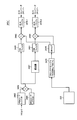
- FIG. 1 is a diagram illustrating a configuration of a position information providing system 10.
- FIG. 4 is a conceptual diagram for explaining a reception state of position information providing apparatus 100 that receives a positioning signal from indoor transmitter 200 of Embodiment 1.
- FIG. 3 is a conceptual diagram for explaining an outline and an operation of a position information providing apparatus 100 according to Embodiment 1.
- FIG. 3 is a block diagram showing a hardware configuration of indoor transmitter 200-1 according to Embodiment 1.
- FIG. FIG. 11 is a diagram conceptually showing one mode of data storage in EEPROM 243 provided in indoor transmitter 200-1. It is a functional block diagram for demonstrating the structure of the modulator 245a. It is a figure showing the structure of the signal 500 transmitted by the transmitter mounted in a GPS satellite.
- FIG. 3 is a block diagram showing a hardware configuration of position information providing apparatus 100.
- FIG. It is a figure for demonstrating the process which the control part 414, the determination part 416, and the indoor positioning part 434 perform.
- FIG. It is a conceptual diagram for demonstrating the outline of a structure and operation
- FIG. FIG. 10 is a block diagram showing a hardware configuration of an indoor transmitter 200-1 ′ according to the second embodiment.
- FIG. 10 is a block diagram illustrating a hardware configuration of an indoor transmitter 200-1 ′′ according to Embodiment 3. It is a functional block diagram for demonstrating the structure of the modulator 245a ''.
- FIG. 1 is a diagram illustrating a configuration of a position information providing system 10.
- the position information providing system 10 flies at an altitude of about 20,000 meters above the ground and transmits GPS positioning signals (hereinafter referred to as “positioning signals”) satellites 110, 111, 112 and 113, and position information providing devices 100-1 to 100-4 functioning as devices for providing position information. That is, the position information providing apparatus operates as a navigation signal receiving apparatus that receives a positioning signal and provides position information to a user.
- the location information providing devices 100-1 to 100-4 are collectively referred to as the location information providing device 100.
- the position information providing device 100 is a terminal having a conventional positioning device, such as a mobile phone, a car navigation system, and other mobile positioning devices. That is, the position information providing apparatus 100 receives the positioning signal and calculates the current position of the position information providing apparatus 100 based on the information included in the received positioning signal.
- a conventional positioning device such as a mobile phone, a car navigation system, and other mobile positioning devices. That is, the position information providing apparatus 100 receives the positioning signal and calculates the current position of the position information providing apparatus 100 based on the information included in the received positioning signal.
- the positioning signal is a so-called spread spectrum signal, for example, a so-called GPS signal.
- the signal is not limited to a GPS signal.
- the positioning system will be described using GPS as an example, but the present invention is also applicable to other satellite positioning systems (Galileo, GLONASS, etc.).
- the center frequency of the positioning signal is 1575.42 MHz, for example.
- the spread frequency of the positioning signal is, for example, 1.023 MHz.
- the frequency of the positioning signal is the same as the frequency of the C / A (Coarse and Access) signal in the existing GPS L1 band. Therefore, since the front end of an existing positioning signal receiving circuit (for example, a GPS signal receiving circuit) can be used, the position information providing apparatus 100 performs signal processing from the front end without adding a new hardware circuit. A positioning signal can be received simply by changing the software.
- the positioning signal may be modulated by a 1.023 MHz rectangular wave.
- the user receives the positioning signal using a receiver that can receive and process a new GPS signal. it can.
- the frequency of the rectangular wave is not limited to 1.023 MHz.
- the frequency for modulation may be determined by a trade-off with existing C / A signals and / or spectrum separation to avoid interference with other signals.
- the GPS satellite 110 is equipped with a transmitter 120 that transmits a positioning signal. Similar transmitters 121, 122, and 123 are mounted on the GPS satellites 111, 112, and 113, respectively.
- the location information providing devices 100-2, 100-3, 100-4 having the same functions as the location information providing device 100-1 can be used in buildings 130 and other places where radio waves are difficult to reach, as will be described below. is there. That is, in the building 130, the indoor transmitter 200-1 is attached to the ceiling of the first floor of the building 130. That is, the indoor transmitter operates as a navigation signal transmission device for transmitting a positioning signal including position information to the reception side. Position information providing apparatus 100-4 receives a positioning signal transmitted from indoor transmitter 200-1. Similarly, indoor transmitters 200-2 and 200-3 are also attached to the ceilings of the second and third floors of the building 130, respectively.
- each indoor transmitter 200-1, 200-2, 200-3 (hereinafter referred to as “ground time”) and the time of the GPS satellites 110, 111, 112, 113 (referred to as “satellite time”). ) May be independent of each other and need not be synchronized. However, each satellite time needs to be synchronized. Therefore, each satellite time is controlled by an atomic clock mounted on each satellite. Moreover, it is preferable that the ground time, which is the time of each indoor transmitter 200-1, 200-2, 200-3, is also synchronized with each other as necessary.
- a spread spectrum signal transmitted as a positioning signal from each transmitter of a GPS satellite is generated by modulating a navigation message with a pseudo noise code (PRN (Pseudo Random Noise) code).
- the navigation message includes time data, orbit information, almanac, ionospheric correction data, and the like.
- Each transmitter 120 to 123 further holds data (PRN-ID (Identification)) for identifying the transmitter 120 to 123 itself or a GPS satellite on which the transmitter 120 to 123 is mounted. Yes.
- the position information providing apparatus 100 has data and a code generator for generating each pseudo-noise code.
- the position information providing apparatus 100 executes a demodulation process, which will be described later, using a code pattern of a pseudo-noise code assigned to each satellite transmitter or each indoor transmitter, and receives the received signal. Can be identified from which satellite or from which indoor transmitter.
- the PRN-ID is included in the data, and it is possible to prevent signal acquisition / tracking with an erroneous code pattern that is likely to occur when the reception level is low.
- the transmitters 120, 121, 122, and 123 each perform an atomic clock, a storage device that stores data, an oscillation circuit, a processing circuit that generates a positioning signal, and a spectrum generated by a signal generated by the processing circuit.
- An encoding circuit for encoding, a transmission antenna, and the like are included.
- the storage device stores an ephemeris, an almanac of each satellite, ionospheric correction data, etc., and a PRN-ID.
- the processing circuit generates a message for transmission using the time information from the atomic clock and each data stored in the storage device.
- each of the transmitters 120 to 123 a code pattern of a pseudo noise code for performing spread spectrum encoding is defined in advance. Each code pattern is different for each transmitter (that is, for each GPS satellite). The encoding circuit spreads the message using such a pseudo-noise code. Each of the transmitters 120 to 123 converts the encoded signal into a high frequency and transmits it to outer space via a transmission antenna.
- the transmitters 120 to 123 transmit spread spectrum signals that do not cause harmful interference with other transmitters.
- “not causing harmful interference” can be ensured by an output level limited to such an extent that interference does not occur.
- This signal is transmitted by a carrier wave called L1 band, for example.
- Each transmitter 120, 121, 122, 123 transmits a positioning signal having the same frequency, for example, according to a spread spectrum communication system. Therefore, even when positioning signals transmitted from the respective satellites are received by the same position information providing apparatus 100-1, the positioning signals are received without mutual interference.
- the positioning signal from the indoor transmitter on the ground similarly to the signal transmitted from the satellite, signals from a plurality of indoor transmitters can be received without mutual interference.
- FIG. 2 shows position information providing apparatus 100 that receives a positioning signal from indoor transmitter 200 according to Embodiment 1 (when indoor transmitters 200-1 to 200-3 are collectively referred to as indoor transmitter 200).
- FIG. 5 is a conceptual diagram for explaining a reception state of (location information providing apparatus 100-1 to 100-4 are collectively referred to as position information providing apparatus 100).
- the indoor transmitter 200 is installed in a fixed place such as a ceiling or side of a building. On the other hand, it is assumed that position information providing apparatus 100 always moves indoors as a user terminal.
- the indoor transmitter 200 is configured as described below to reduce the instability of the system due to multipath as one effect.
- the indoor transmitter 200 includes two transmission antennas TX-ANT1 and TX-ANT2, and uses transmission diversity among so-called spatial diversity schemes.
- the transmission antennas TX-ANT1 and TX-ANT2 are arranged at physically separated points. The distance between the two antennas is preferably about several tens of cm to 1 m.
- the signals transmitted from the transmission antennas TX-ANT1 and TX-ANT2 transmit data having the same content, but are configured to be identifiable in the position information providing apparatus 100.
- the indoor transmitter 200 employs a so-called Code Division Multiple Access system. Therefore, the signal frequency transmitted from each antenna is the same.
- position information providing apparatus 100 receives signals from one antenna. It is possible to select a signal.
- the indoor transmitter 200 it is generally possible to use the reception diversity method in the diversity system as well as the transmission diversity.
- the indoor transmitter 200 of Embodiment 1 does not employ reception diversity. This is because a reception diversity system needs to mount a plurality of antennas on the receiving terminal side, and transmission diversity is more advantageous in terms of cost, operation, and portability.
- the number of antennas in transmission diversity is not limited to two, and more generally two or more (eg, three, four, etc.) may be used.
- the indoor transmitter 200 of Embodiment 1 a plurality of antennas are mounted on the transmission side, and only one antenna is mounted on the reception side.
- the indoor transmitter 200 uses a pseudo-random noise (PRN) code (hereinafter referred to as a “PRN code”), which is a spread code for spread spectrum, to distinguish a plurality of transmission signals. To achieve high signal selectivity.
- PRN code pseudo-random noise
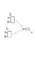
- FIG. 3 is a conceptual diagram for explaining an outline and an operation of the position information providing apparatus 100 according to the first embodiment.
- position information providing apparatus 100 is spread-spectrum encoded with different codes (here, code PRN180 and code PRN181) transmitted from indoor transmitter 200, and transmits antennas TX-ANT1 and TX.
- the positioning signals transmitted from ANT2 are received by the receiving antenna RX-ANT.
- the number of the spreading code assigned to the spreading code from the indoor transmitter 200 is not particularly limited to the example of FIG. 3, and the positioning signal from the satellite and the indoor signal are not limited when designing the system. Any configuration may be used as long as a different code is assigned so that a positioning signal from the transmitter 200 can be determined.
- the positioning signal received by the receiving antenna RX-ANT is converted into a baseband signal by the front end 102.
- the front end 102 includes a filter for extracting a high frequency received signal, an amplifier circuit for amplifying the high frequency signal, a down converter, an A / D converter, and the like.
- the signals from the front end 102 are correlators 110.1 to 110. By n, the correlation with the replica signal of the spreading code is detected. Since the PRN code used as the spreading code is stored in advance in the position information providing apparatus 100 on the receiving side, the position information providing apparatus 100 has a plurality of possibilities that may be transmitted from the indoor transmitter 200. Correlation processing is performed in parallel for the PRN code. In the configuration shown in FIG. 3, only correlator 110.1 for code PRN180 and correlator 110.2 for code PRN181 are representatively described. Actually, for example, when the position information providing apparatus 100 moves indoors from the outdoors, the correlators 110.1 to 110.
- n is provided not only for spreading codes assigned in advance to the indoor transmitter 200, but also for spreading codes assigned to GPS satellites, in a number that allows correlation processing in parallel. Desirably, the number of correlators 110... Corresponding to the sum of the total number of spreading codes that can be pre-assigned to indoor transmitter 200 and the total number of spreading codes that can be pre-assigned to GPS satellites orbiting the earth. 1-110. It is desirable that n be provided and that they perform correlation processing in parallel.
- the corresponding spreading code (PRN code) PRN180 can be sampled as a number of samples that can be sampled as a time delay (in the case of a m-chip signal, 2 m chips for every 1/2 chip). Correlator is provided only for (min), and the correlation processing is executed in parallel for each time delay.
- PRN code spreading code
- the position information providing apparatus 100 searches the PRN code of the transmission signal independently and asynchronously.
- the first PRN code can be captured first
- another correlator correlator
- a synchronized diversity signal If a synchronized diversity signal is present, it can be captured very quickly.
- correlators 110.1 to 110. n corresponding to bit decoders 414.1 to 414. n is provided.
- correlators 110.1 to 110. n are subsequently correlated to correlators 110.1 to 110. bit decoders 414.1 to 414. provided corresponding to n. Decoded by n.
- determination unit 416 determines whether position information providing apparatus 100 is currently indoors or outdoors. The determination unit 416 also determines whether or not the received signal is transmitted by a diversity method. Thereafter, details of processing executed for positioning will be described later.
- the position information providing apparatus 100 has a very short time, i) determination of which spreading code the received positioning signal corresponds to, and ii) the received signal is a positioning signal from a GPS satellite. Or whether the signal is a positioning signal from the indoor transmitter 200 can be executed.
- m is a bit decoder 414.1-414. Based on the signal from n, control is performed to establish and maintain a synchronous loop.
- the positioning signal from the indoor transmitter 200 is assumed to be spread by the code PRN180 and the code PRN181, the correlator 110.1 and the correlator 110 corresponding to these codes in a short time.
- the positioning signal from .2 is synchronized and the synchronization is established.
- the first data packet is completely received, and O. K. If determined to be O. K.
- the determination data packet is compared with the packet data of another channel (corresponding to another correlator). When this data is the same, each PRN number is assigned to the diversity channel.
- the position information providing apparatus 100 performs positioning by selecting one of the signals from the two channels with which synchronization has been established.
- FIG. 4 is a block diagram showing a hardware configuration of indoor transmitter 200-1 of the first embodiment.
- the indoor transmitter 200-1 will be described with reference to FIG.
- the indoor transmitter 200-1 is electrically connected to a wireless interface (hereinafter referred to as “wireless I / F”) 210, a digital processing block 240, and a digital processing block 240 for the operation of each circuit portion.
- a reference clock input / output block (hereinafter referred to as a “reference clock I / O block”) 230 for supplying a reference clock
- an analog processing block 250 electrically connected to the digital processing block 240
- an analog processing Transmitting antennas TX-ANT1 and TX-ANT2 (not shown) that are electrically connected to the block 250 and transmit signals for positioning, and supply power supply potentials to each part of the indoor transmitter 200-1. Power supply (not shown).
- the power source may be built in the indoor transmitter 200-1 or may be configured to accept external power supply.
- the wireless I / F 210 is a wireless communication interface, and receives commands from the outside through short-range wireless communication, for example, Bluetooth (Bruetooth), wireless communication such as PHS (Personal Handyphone System) and a mobile phone network. Or receiving data of setting parameters and programs (firmware or the like) with the outside, or transmitting data to the outside as necessary.
- Bluetooth Bluetooth
- PHS Personal Handyphone System
- the indoor transmitter 200-1 can be set parameters such as position data transmitted by the indoor transmitter 200-1 even after installation on an indoor ceiling or the like. (Data representing the location where the indoor transmitter 200-1 is installed) can be changed, or by changing the firmware, it is possible to cope with different communication systems.
- a wireless interface is assumed.
- the wired interface is used. It is also possible to do.
- the digital processing block 240 is mounted on the processor 241 that controls the operation of the indoor transmitter 200-1 according to a command from the wireless I / F 210 or according to a program, and a program executed by the processor 241.
- a RAM Random Access Memory
- EEPROM Electrically Erasable and Programmable Read-Only Memory
- a field programmable gate array (hereinafter referred to as “FPGA”) 245 for generating a baseband signal transmitted from the indoor transmitter 200-1 and the FPGA 245 among the data from the wireless I / F 210, EEPROM for storing firmware ROM 244 and digital / analog converters (hereinafter referred to as “D / A converters”) 247.1 and 247.2 that convert the baseband signal output from FPGA 245 into an analog signal and apply it to analog processing block 250 .
- FPGA field programmable gate array
- the digital processing block 240 generates data serving as a source of a signal transmitted by the indoor transmitter 200-1 as a positioning signal. As described above, the source data is subjected to spreading processing with different spreading codes for the transmission antennas TX-ANT1 and TX-ANT2. The digital processing block 240 sends the generated data as two bit streams to the analog processing block 250.
- the firmware program stored in the EEPROM 244 is loaded into the FPGA 245 when the FPGA 245 is powered on.
- This firmware program information (bit stream data) is loaded into a configuration memory configured by SRAM (Static Random Access Memory) 246 in FPGA 245.
- SRAM Static Random Access Memory
- Each bit data of the loaded bit stream data becomes an information source of a circuit realized on the FPGA 245, and a circuit specified by the firmware program is realized by customizing resources provided in the FPGA 245.
- the FPGA 245 can achieve high versatility and flexibility by having configuration data outside without depending on the hardware.
- the processor 241 sets, as parameters set in the indoor transmitter 200-1, in the SRAM 246 (register) of the FPGA 245 based on data stored in the EEPROM 243 in accordance with an external command received from the wireless I / F 210.
- the processor 241 sets, as parameters set in the indoor transmitter 200-1, in the SRAM 246 (register) of the FPGA 245 based on data stored in the EEPROM 243 in accordance with an external command received from the wireless I / F 210.
- the storage device for storing the program or data is not limited to the EEPROM 243 or 244. It may be at least a storage device that can store data in a nonvolatile manner, or a battery backup RAM (Random Access Memory) that can retain stored data even when the power is turned off. Further, when external data is input, any storage device capable of writing data may be used.
- the data structure of data stored in the EEPROM 243 will be described later.
- the analog processing block 250 uses the two bitstreams output from the digital processing block 240 to modulate a 1.57542 GHz carrier wave to generate a transmission signal, which is transmitted to the two transmission antennas TX-ANT1 and TX-ANT2, respectively. Send it out.
- the signal is transmitted as a diversity signal from transmission antennas TX-ANT1 and TX-ANT2.
- the two signals output from the D / A converter 247 of the digital processing block 240 are up-converted by the up-converters 252.1 and 252.2, and bandpass filters (BPF) 253.1 and 253.2 are obtained.
- BPF bandpass filters
- the clocks used in the up converters 252.1 and 252.2 and the up converters 255.1 and 255.2 are the clocks supplied from the reference clock I / O block 230 to the FPGA 245, and the multiplier 251. The doubled one is used.
- a signal having the same configuration as the signal for positioning from the satellite is transmitted from the indoor transmitter 200-1 by the diversity method.
- the content of the signal is not exactly the same as the content included in the positioning signal transmitted from the satellite.
- An example of the configuration of a signal transmitted from the indoor transmitter 200-1 will be described later.
- the FPGA 245 is used as the arithmetic processing device for realizing the digital signal processing in the digital processing block 240.
- other arithmetic processing can be used as long as the device can change the modulation function of the wireless device by software.
- a device may be used.
- the clock signal (Clk) is supplied from the digital processing block 240 to the analog processing block 250, but may be supplied directly from the reference clock I / O block 230 to the analog processing block 250.
- digital processing block 240 and the analog processing block 250 are separately shown in the present embodiment, but physically, they may be mixedly mounted on one chip. .
- the reference clock I / O block 230 supplies the digital processing block 240 with a clock signal that defines the operation of the digital processing block 240 or a clock signal for generating a carrier wave.
- the reference clock I / O block 230 supplies the clock signal to the digital processing block 240 and the like based on the synchronization signal supplied from the external clock generator to the external synchronization link port 220. To do.
- the reference clock I / O block 230 selects an external clock signal supplied to the external clock port 221 by the multiplexer 232, and outputs a clock signal output from a PLL (Phase Locked Loop) circuit 233. In synchronization with the external clock, the synchronized clock signal is supplied to the digital processing block 240 and the like.
- PLL Phase Locked Loop
- the reference clock I / O block 230 selects the internal clock signal generated by the internal clock generator 231 with the multiplexer 232 and outputs the clock signal output from the PLL (Phase Locked Loop) circuit 233. Are synchronized with the internal clock, and the synchronized clock signal is supplied to the digital processing block 240 and the like.
- PLL Phase Locked Loop
- the internal state of the transmitter (for example, a “PLL control” signal) can be monitored by a signal output from the wireless I / F 210 by the processor 241.
- the wireless I / F 210 can accept input of other data to be transmitted from the indoor transmitter 200-1.
- the other data is, for example, data (position data) representing a place where the indoor transmitter 200-1 is installed, for example, text data.
- advertisement data can be input to the indoor transmitter 200-1 as the other data.
- the code pattern of the pseudo spread code (PRN code) is input to the indoor transmitter 200-1, the code pattern is written in a predetermined area in the EEPROM 243. Thereafter, the written PRN-ID is included in a signal for positioning. Other data is also written in an area reserved in advance in the EEPROM 243 according to the type of the data.
- PRN code pseudo spread code
- the two signals transmitted from the two transmission antennas are described as being synchronized on the transmission side.
- These synchronizations also function preferentially when returning from synchronization due to signal loss due to multipath.
- FIG. 5 is a diagram conceptually showing one mode of data storage in EEPROM 243 provided in indoor transmitter 200-1.
- the EEPROM 243 includes areas 310 to 340 for storing data.
- a transmitter ID is stored as a number for identifying the transmitter.
- the transmitter ID is, for example, a number and / or an alphabetic character or other combination that is written in a memory in a nonvolatile manner when the transmitter is manufactured.
- the PRN-ID of the pseudo spread code assigned to the transmitter is stored in the area 310.
- the name of the transmitter is stored in the area 320 as text data, for example.
- the code patterns of the two pseudo-spread codes assigned to the transmitter are stored in the area 330.
- the code pattern of the pseudo spreading code is a finite number of codes assigned in advance for the position information providing system according to the embodiment of the present invention from among code patterns belonging to the same sequence as the pseudo spreading code for satellites. It is selected from the patterns.
- the code pattern is a code pattern different from the code pattern of the pseudo spread code assigned to each satellite.
- the number of indoor transmitters depends on the size of the installation location of each transmitter or the configuration of the installation location (such as the number of buildings) ), And a plurality of indoor transmitters more than the number of code patterns may be used. Therefore, there can be a plurality of transmitters having the same pseudo-spread code pattern. In this case, the installation location of the transmitter having the same code pattern may be determined in consideration of the signal output. By doing so, it is possible to prevent a plurality of positioning signals using the same pseudo spread code code pattern from being received at the same time by the same position information providing apparatus.
- the position data for specifying the location where the indoor transmitter 200-1 is installed is stored in the area 340.
- the position data is represented as a combination of latitude, longitude and height, for example.
- an address, a building name, and the like may be stored in the area 320.
- an indoor transmitter using only the data such as “combination of latitude, longitude, height”, “address, name of building”, “combination of height, longitude, altitude and address, name of building”.
- Data capable of specifying the installation location 200-1 is collectively referred to as “position specifying data”.
- the PRN-ID, the name of the communication device, the code pattern of the pseudo-spreading code, and the position specifying data can be changed to other data input via the wireless interface 210.
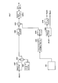
- FIG. 6 shows a C / A (coarse / access) code baseband signal, which is a positioning signal put on the L1 band (1575.42 MHz) of the current GPS signal carrier among the circuits realized by the FPGA 245. It is a functional block diagram for explaining the configuration of a modulator 245a for performing modulation according to the signal format.
- the FPGA 245 performs quadrature modulation when performing modulation in accordance with the baseband signal of the L1C code, which is a positioning signal used in the L1 band of a new positioning satellite system (for example, the Japanese Quasi-Zenith Satellite System). It is programmed to have a configuration corresponding to signal modulation of two phases (I phase and Q phase). Therefore, FIG. 6 exemplarily shows the case where the positioning code is one system, but in the above-described “new positioning satellite system”, two systems are orthogonally modulated. The present invention can also be applied to such multiple systems.
- the baseband signal of the L1C code which is a positioning signal used in the L1 band of a new positioning satellite system (for example, the Japanese Quasi-Zenith Satellite System). It is programmed to have a configuration corresponding to signal modulation of two phases (I phase and Q phase). Therefore, FIG. 6 exemplarily shows the case where the positioning code is one system, but in the above-described “new positioning satellite system”, two systems
- BPSK Binary Phase Shift Keying
- QPSK Quadrature Phase Shift Keying
- FIG. 6 basically has a configuration of a BPSK modulator. Yes.
- an independent circuit may be programmed in each method in accordance with the modulation method variably realized by the modulator 245a.
- modulator 245a generates message data based on PRN code registers 2462 and 2464 that receive and store the PRN code stored in EEPROM 243, and position data stored in EEPROM 243.
- Message code registers 2466 and 2468 are provided for receiving and storing message data in accordance with a signal format of a C / A code from a device (not shown).
- the PRN code set in the EEPROM 243 is input to the PRN code registers 2462 and 2464 from the outside, and data of different spreading codes (PRN codes) is stored in the message code registers 2466 and 2468, respectively. .
- the modulator 245a further multiplies the time series data read from the PRN code register 2462 and the time series data read from the message code register 2466, and the time series data and message code read from the PRN code register 2464.
- a multiplier 2454 that multiplies the time-series data read from the register 2468, an FIR filter 2460 that functions as a bandpass filter for the output from the multiplier 2452, and a bandpass filter for the output from the multiplier 2454. And a functioning FIR filter 2461.
- the modulator 245a further synchronizes with the signal from the clock manager circuit 2472 and the clock manager circuit 2472 that generates the modulation reference clock according to the signal format based on the clock signal from the reference clock I / O block 230.
- a lookup table 2474 for outputting data corresponding to a preset sine wave; a multiplier 2463 for multiplying a signal corresponding to the sine wave output from the lookup table 2474 and a signal from the FIR filter 2460;
- a multiplier 2465 for multiplying the signal corresponding to the sine wave output from the look-up table 2474 and the signal from the FIR filter 2461, and the signals from the multipliers 2463 and 2465 are buffered, and the D / A converter 247.1. And 247.2 And an output buffer 2470.1 and 2470.2 for respective output.
- the above-described modulator 245a is configured to output a signal compatible with the current GPS signal (signal compatible with L1 C / A code: L1 C / A compatible signal) by the firmware of FPGA 245.
- the modulator 245a generates a BPSK-modulated signal by modulating the “latitude / longitude / height” information of the transmitter as a message.
- the term “compatible signal” means a signal that can be received with a common front end unit as a receiver because it has a common signal format.
- the “height information” is information on the height of the place where the indoor transmitter 200 is installed, and may be, for example, data on altitude, or represents the number of floors of a building or the number of underground floors. Data may be used. Alternatively, the “height information” may be data (Floor-ID) for identifying the floor number of the building.
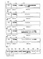
- FIG. 7 is a diagram illustrating a configuration of a signal 500 transmitted by a transmitter mounted on a GPS satellite.
- the signal 500 is composed of five 300-bit subframes, that is, subframes 510 to 550.
- Subframes 510 to 550 are repeatedly transmitted by the transmitter.
- Each of subframes 510 to 550 has, for example, 300 bits and is transmitted at a bit rate of 50 bps (bit per second). Therefore, in this case, each subframe is transmitted in 6 seconds.
- the first subframe 510 includes a 30-bit transport overhead 511, 30-bit time information 512, and 240-bit message data 513.
- the time information 512 includes time information acquired when the subframe 510 is generated, and a subframe ID.
- the subframe ID is an identification number for distinguishing the first subframe 510 from other subframes.
- the message data 513 includes a GPS week number, clock information, health information of the GPS satellite, orbit accuracy information, and the like.
- the second subframe 520 includes a 30-bit transport overhead 521, 30-bit time information 522, and 240-bit message data 523.
- the time information 522 has the same configuration as the time information 512 in the first subframe 510.
- the message data 523 includes an ephemeris.
- the ephemeris ephemeris
- the ephemeris is highly accurate information that is sequentially updated by a control station that manages the navigation of the satellite.
- the third subframe 530 has the same configuration as the second subframe 520. That is, the third subframe 530 includes a 30-bit transport overhead 531, 30-bit time information 532, and 240-bit message data 533.
- the time information 532 has the same configuration as the time information 512 in the first subframe 510.
- the message data 533 includes an ephemeris.
- the fourth subframe 540 includes a 30-bit transport overhead 541, 30-bit time information 542, and 240-bit message data 543.
- the message data 543 includes almanac information, satellite health information summary, ionospheric delay information, UTC (Coordinated Universal Time) parameters, and the like.
- the fifth subframe 550 includes a 30-bit transport overhead 551, 30-bit time information 552, and 240-bit message data 553.
- Message data 553 includes almanac information and a summary of satellite health information.
- Each of the message data 543 and 553 is composed of 25 pages, and the above different information is defined for each page.
- the almanac information is information representing a general orbit of a satellite, and includes information on all GPS satellites as well as the satellite.
- Subframes 510 to 550 are transmitted from transmitters 120, 121, and 122, respectively.
- the position of the position information providing apparatus 100 includes the maintenance / management information included in the transport overheads 511 to 551, time information 512 to 552, and a message. Calculated based on the data 513 to 553.
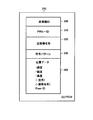
- the signal 560 has the same data length as the message data 513 to 553 included in the subframes 510 to 550. Signal 560 differs from subframes 510-550 in that it has data representing the location of the source of signal 560 in place of orbit information represented as ephemeris (message data 523, 533).
- the signal 560 includes a 6-bit PRN-ID 561, a 15-bit transmitter ID 562, an X coordinate value 563, a Y coordinate value 564, a Z coordinate value 565, an altitude correction coefficient (Zhf) 566, an address 567 and a reserve area 568.
- Signal 560 is transmitted from indoor transmitters 200-1, 200-2, 200-3 in place of message data 513-553 included in subframes 510-550.
- PRN-ID 561 is an identification number of a code pattern of a group of pseudo-noise codes assigned in advance to a transmitter (for example, indoor transmitters 200-1, 200-2, 200-3) that is a transmission source of signal 560. It is.
- the PRN-ID 561 is different from the identification number of the code pattern of a group of pseudo-noise codes assigned to each transmitter mounted on each GPS satellite, but the PRN-ID 561 is a code pattern generated from a code string of the same series. It is the number assigned to it.
- the position information providing apparatus obtains one of the code patterns of the pseudo-noise code assigned for the indoor transmitter from the received signal 560, so that the signal is transmitted in the subframes 510 to 550 transmitted from the satellite. It is specified whether there is a signal 560 transmitted from an indoor transmitter.
- the X coordinate value 563, the Y coordinate value 564, and the Z coordinate value 565 are data representing the position where the indoor transmitter 200-1 is attached.
- the X coordinate value 563, the Y coordinate value 564, and the Z coordinate value 565 are represented, for example, as latitude, longitude, and height.
- the altitude correction coefficient 566 is used to correct the altitude specified by the Z coordinate value 565.
- the altitude correction coefficient 566 is not an essential data item. Therefore, when the accuracy higher than the height specified by the Z coordinate value 565 is not required, the coefficient may not be used. In this case, for example, data representing “NULL” is stored in the area allocated for altitude correction coefficient 566.
- “address, building name”, “advertisement data”, “traffic information”, “weather information”, and “disaster information” are allocated to the reserve area 568, but other data may be allocated.
- the signal transmitted from the indoor transmitter 200 may be an “L1C compatible signal” corresponding to a positioning signal from a new positioning satellite.
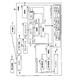
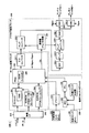
- FIG. 8 is a block diagram showing a hardware configuration of position information providing apparatus 100.
- the position information providing apparatus 100 includes an antenna 402, an RF (Radio Frequency) front circuit 404 electrically connected to the antenna 402, a down converter 406 electrically connected to the RF front circuit 404, and a down converter An A / D (Analog to Digital) converter 408 electrically connected to 406, a baseband processor 412 that receives a signal from the A / D converter 408, performs correlation processing, and is electrically connected to the baseband processor 412 A memory 420 connected to the baseband processor 412, a navigation processor 430 electrically connected to the baseband processor 412, and a display 440 electrically connected to the navigation processor 430.
- RF Radio Frequency
- the baseband processor 412 includes correlators 410.1 to 410. electrically connected to the A / D converter 408. n and correlators 410.1-410. n Numerically Controlled Oscillators (NCO) 411.1 to 411 for supplying a clock as a reference for timing of correlation processing. n and correlators 410.1-410. n, which respectively receive signals from n and perform integration processing for a predetermined period. n.
- NCO Numerically Controlled Oscillators
- the baseband processor 412 further adds the accumulators 412.1 to 412. based on the software stored in the memory 420. n and the correlator 410.1-410. n, NCO 411.1-411. n and integrators 412.1-412.
- movement of n is included.
- the baseband processor 412 performs correlation processing in consideration of the influence of the Doppler effect of the received signal, and performs not only a search for the PRN code and its delay component but also the NCO 411 according to the control of the control unit 414. 1-41.
- the frequency search is also performed by controlling the frequency of n.
- the correlators 410.1 to 410. n, and integrators 412.1-412. n may be configured to be hardware independent of the baseband processor 412.
- the function with n can also be realized as software.
- the memory 420 includes a plurality of areas for storing a PRN code pattern, which is data for identifying each transmission source of the positioning signal.
- a PRN code pattern which is data for identifying each transmission source of the positioning signal.
- the memory 420 when 48 code patterns are used, the memory 420 includes regions 421-1 to 421-48 as shown in FIG. In another aspect, when more code patterns are used, more area is secured in the memory 420. Conversely, a code pattern that is smaller than the number of areas reserved in the memory 420 may be used.
- the code pattern of the pseudo-noise code for the first satellite is stored in area 421-1. From this, the code pattern is read out, and the cross-correlation process with the received signal is performed, whereby the signal can be tracked and the navigation message included in the signal can be decoded.
- the method of storing and reading the code pattern is exemplarily shown, but a method of generating a code pattern by a code pattern generator is also possible.
- the code pattern generator is realized, for example, by combining two feedback shift registers. It should be noted that the configuration and operation of the code pattern generator can be easily understood by those skilled in the art. Therefore, detailed description thereof will not be repeated.
- the code pattern of the pseudo-noise code assigned to the indoor transmitter that transmits the positioning signal is stored in areas 421-37 to 421-48.
- the code pattern of the assigned pseudo-noise code for the first indoor transmitter is stored in areas 421-37 and 421-38.
- PRN code spreading code
- an indoor transmitter having 12 code patterns can be used, but there is no indoor transmitter that uses the same code pattern in a range that can be received by the same position information providing apparatus.
- each indoor transmitter may be arranged. By doing so, it is possible to install six or more indoor transmitters on the same floor of the building 130, for example.
- the navigation processor 430 determines the source of the positioning signal based on the data output from the control unit 414, and determines whether the received positioning signal is a diversity transmission, and controls the operation of the control unit 414.
- An outdoor positioning unit 432 for measuring the position of the outdoor location information providing apparatus 100 based on a signal output from the determination unit 416 based on software stored in the memory 420, and a determination unit
- an indoor positioning unit 434 for deriving information representing the position of the position information providing apparatus 100 indoors based on the data output from 416.
- the antenna 402 can receive the positioning signals transmitted from the GPS satellites 110, 111, and 112 and the positioning signals transmitted from the indoor transmitter 200-1.
- the antenna 402 can transmit and receive a signal for wireless telephone or a signal for data communication in addition to the above-described signal.
- the filter of the RF front circuit 404 and the LNA (Low Noise Amplifier) circuit receive a signal received by the antenna 402 and perform noise reduction or filter processing for outputting only a signal having a predetermined bandwidth.
- a signal output from the RF front circuit 404 is input to the down converter 406.
- the down converter 406 amplifies the signal output from the RF front circuit 404 and outputs it as an intermediate frequency. This signal is input to the A / D converter 408.
- the A / D converter 408 performs digital conversion processing on the input intermediate frequency signal and converts it into digital data.
- the digital data is stored in the correlator 410.1-410. n.
- Correlator 410.1-410. n performs a correlation process between the code pattern read out from the memory 420 by the control unit 414 and the received signal.
- Correlator 410.1-410 Each of the n correlators simultaneously executes matching between the received positioning signal and a code pattern generated for demodulating the positioning signal based on the control signal output from the control unit 414.
- the control unit 414 includes the correlators 410.1 to 410.
- a command for generating a code pattern (replica pattern) reflecting a delay that may occur in the pseudo-noise code (shifting the code phase) is given to each of n.
- This command is, for example, the number of satellites ⁇ 2 ⁇ 1023 (the length of the code pattern of the pseudo-noise code used) in the current GPS.
- Each correlator 410.1-410. n generates code patterns having different code phases using a code pattern of a pseudo-noise code defined for each satellite based on a command given to each. Then, one of all the generated code patterns matches the code pattern of the pseudo noise code used for modulation of the received positioning signal.
- the number of correlators necessary for performing the matching process using each code pattern is converted into parallel correlators 410.1 to 410.
- the code pattern of the pseudo-noise code can be specified in a very short time. This processing can be similarly applied when the position information providing apparatus 100 receives a signal from an indoor transmitter. Therefore, even when the user of the position information providing apparatus 100 is indoors, the position information can be acquired in a very short time.
- the parallel correlators 410.1 to 410. n can be matched in parallel at the maximum for all of the code pattern of the pseudo-noise code specified for each satellite and the code pattern of the pseudo-noise code specified for each indoor transmitter. .
- all of the code patterns of pseudo-noise codes specified for each satellite and each indoor transmitter are as follows: Even when matching is not performed collectively, the time required to acquire the position information can be greatly shortened by parallel processing using a plurality of correlators.
- the satellite and the indoor transmitter transmit signals by the spread spectrum method which is the same communication method
- the pseudo-noise code patterns assigned to the satellite and the indoor transmitter can be used in the same series.
- the parallel correlator can be shared for both the signal from the satellite and the transmission from the indoor transmitter, and the reception processing can be performed in parallel without specially distinguishing between the two.
- Parallel correlators 410.1-410. n uses each code pattern to track the positioning signal received by the position information providing apparatus 100 and to perform processing for specifying a code pattern having an arrangement that matches the bit arrangement of the positioning signal.
- the determination unit 416 specifies the code pattern of the pseudo-noise code, so that the position information providing apparatus 100 transmits the received positioning signal from which satellite or the indoor transmitter. Can be determined.
- the determining unit 416 also determines whether or not the positioning signal is diversity-transmitted. Further, the position information providing apparatus 100 can demodulate and decode the message using the specified code pattern.
- the determination unit 416 performs the determination as described above, and sends data corresponding to the determination result to the navigation processor 430.
- the determination unit 416 determines whether the PRN-ID included in the received positioning signal is a PRN-ID assigned to the indoor transmitter 200-1 other than the transmitter mounted on the GPS satellite.
- a spare code for example, 36 pseudo-noise codes are used.
- PRN-01 to PRN-24 are used as numbers for identifying each GPS satellite (PRN-ID)
- PRN-25 to PRN-36 are used as numbers for identifying spare satellites.
- the spare satellite is a satellite that is newly launched in addition to the satellite that was originally launched. That is, such a satellite is launched in preparation for a failure of a GPS satellite or a transmitter mounted on the GPS satellite.
- PRN-ID to PRN-48 are assigned to the indoor transmitters according to the arrangement of the indoor transmitters, for example. Therefore, if a transmission output that does not interfere with signals transmitted from each indoor transmitter is used, the same PRN-ID may be used for different indoor transmitters. With such an arrangement, more transmitters can be used than the number of PRN-IDs allocated for terrestrial transmitters.
- the determination unit 416 refers to the code pattern 422 of the pseudo-noise code stored in the memory 420, and converts the code pattern acquired from the received positioning signal into the code pattern assigned to the indoor transmitter. Determine whether they match. If these code patterns match, the determination unit 416 determines that the positioning signal is transmitted from the indoor transmitter. If not, the determination unit 416 determines that the signal is transmitted from a GPS satellite, and stores in the memory 420 which satellite the allocated code pattern is the code pattern assigned to. It is determined with reference to the code pattern. Although an example in which a code pattern is used is shown as an aspect of determination, the above determination may be made by comparing other data. For example, a comparison using PRN-ID may be used for the determination.
- the determination unit 416 sends data acquired from the specified signal to the outdoor positioning unit 432.
- the data obtained from the signal includes a navigation message.
- determination unit 416 sends the data acquired from the signal to indoor positioning unit 434.
- This data is a coordinate value set in advance as data for specifying the position of the indoor transmitter 200-1.
- a number that identifies the transmitter may be used.
- the outdoor positioning unit 432 executes a process for calculating the position of the position information providing apparatus 100 based on the data sent from the determination unit 416. Specifically, the outdoor positioning unit 432 calculates the propagation time of each signal using data included in signals transmitted from three or more GPS satellites (preferably four or more), and the calculation result Based on the above, the position of the position information providing apparatus 100 is calculated. This process is executed using a known satellite positioning method. This process can be easily understood by those skilled in the art. Therefore, the details of the description will not be repeated.
- the indoor positioning unit 434 performs a positioning process when the position information providing apparatus 100 exists indoors based on the data output from the determination unit 416.
- indoor transmitter 200-1 transmits a positioning signal including data for specifying a location (position specifying data). Therefore, when the position information providing apparatus 100 receives such a signal, data included in the signal can be taken out and used as the position of the position information providing apparatus 100 using the data.
- the indoor positioning unit 434 performs this process.
- Data calculated by the outdoor positioning unit 432 or the indoor positioning unit 434 is used for display on the display 440. Specifically, these data are incorporated into the data for displaying the screen, and an image representing the measured position or an image for displaying the place where the indoor transmitter 200-1 is installed is generated. Displayed on the display 440.
- the position information providing apparatus 100 includes a communication unit 450 for exchanging data with the outside, for example, with a position information providing server (not shown) under the control of the control unit 414. .
- the antenna 402 in signal processing from reception of a positioning signal to generation of information displayed on the display, the antenna 402, the RF front circuit 404, the down converter 406, and the A / D converter 408 are: It is configured by hardware, and the processing of the baseband processor 412 and the navigation processor 430 can be executed by a program stored in the memory 420.
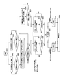
- FIG. 9 is a diagram for describing processing executed by the control unit 414, the determination unit 416, and the indoor positioning unit 434.
- the indoor positioning unit 434 performs processing shown in FIG. Among these, positioning calculation processing is performed.
- the outdoor positioning unit 432 is the same as normal GPS positioning. By the processing, positioning of the current position of the position information providing apparatus 100 is performed. The branch for processing this normal GPS signal is not shown in FIG.
- step S100 when the reception process is started (step S100), correlators 410.1 to 410.4 are controlled according to the control of control unit 414.
- the control unit 414 performs acquisition and synchronization processing in parallel. For example, in the present embodiment, search and acquisition is performed in parallel and asynchronously for two channels CH1 and CH2 corresponding to signals transmitted from the transmission antennas TX-ANT1 and TX-ANT2 by the indoor transmitter 200. Processing is performed (steps S102 and S104).
- the “channel” refers to a communication path between one transmission antenna and the position information providing apparatus 100, and a correlator corresponds to this.
- asynchronous means that reception processing is performed without particularly linking information about reception timing in tracking acquisition processing for one spreading code and information about reception timing in tracking acquisition processing for another spreading code. To do.
- Such search and acquisition processing is continued until acquisition is completed and a synchronous loop is established for any of the channels under the control of the control unit 414 (steps S106 and S108).
- step S110 When either one of the channels CH1 and CH2 has established a synchronization loop early and the determination unit 416 determines that this one channel is a positioning signal from the indoor transmitter 200
- the control unit 414 performs search and acquisition processing for the other channel CH2 in accordance with the synchronization timing (step S110). That is, using the information on the reception timing of the spreading code used to establish a synchronization loop in one channel, the spreading code of the other channel is also delayed by the corresponding reception timing. Perform tracking and capture processing. Further, in the location information providing apparatus 100, when it is stored in advance which spreading code is paired with respect to one indoor transmitter, if synchronization acquisition can be performed for one channel, which PRN code for the other channel can be obtained. You can see if is compatible. This makes it possible to acquire synchronization on the other channel even earlier.
- step S112 when the determination unit 416 determines that the channel with which synchronization is established is a positioning signal from the indoor transmitter 200, is synchronization established with respect to the two channels within a predetermined time, for example? It is determined whether or not (step S112).
- the process proceeds to the next steps SS114 and S116.
- the control unit 414 further determines the other channels independently of the already established channels, that is, the synchronization is established.
- the processing for tracking and acquiring other spreading codes is performed without depending on the reception timing information of the channel being used (step S118).
- the process proceeds to the next steps SS114 and S116.
- control unit 414 independently decodes the signal for one packet for each channel with respect to the synchronization-acquired channel (steps S114 and S116).
- the control unit 414 performs a parity check on the decoded signal (steps S122 and S124), and when the synchronization loop is established for two channels, the parity check is performed for both channels.
- K The reception and decoding processing of the signal for one packet is continued until
- the parity check for both channels is O.D. K. Then, the determination unit 416 compares the contents of the data in the packets received on the two channels (step S126).
- the determination unit 416 determines that the diversity transmission from the indoor transmitter 200 is received on a separate channel and notifies the indoor positioning unit 434 To do. On the other hand, when the contents of the data in the packet do not match, the indoor positioning unit 434 is notified that the positioning signals from two different indoor transmitters have been received.
- the indoor positioning unit 434 When the indoor positioning unit 434 receives the diversity-transmitted signal, the indoor positioning unit 434 selects one of the two channels, and based on the positioning signal received on the selected channel, the indoor positioning unit 434 uses the position specifying data in the message to Information is acquired (step S128), and a positioning result is output (step S132). At this time, in “channel selection”, for example, the channel having the stronger intensity is selected from the two channels. Furthermore, although not particularly limited, for example, when the strength of the positioning signal from the indoor transmitter 200 is set to a different level according to the transmitter, the signal transmitted from the indoor transmitter 200 is not transmitted to the transmitter side. Information (intensity information) indicating a set rank (for example, any one of four ranks) of radio field intensity may be included. In this case, the received radio wave intensity may be normalized based on the intensity information, and the signal of the channel that is determined to be stronger than the normalized signal may be selected.
- channel selection is not particularly limited, but may be performed, for example, by selecting a channel with a lower error rate of the received signal.
- the indoor positioning unit 434 when the indoor positioning unit 434 receives signals transmitted from independent indoor transmitters, the indoor positioning unit 434 integrates the position specifying data of the two channels (step S130) and outputs a positioning result (step S132). .
- the integration of the position specifying data is not particularly limited, the position data of the two indoor transmitters may be calculated by calculating the position of the intermediate point.
- the data comparison does not necessarily need to be based on the decoded signal for one packet, and the comparison may be performed in units of smaller data. For example, comparison may be performed for bits in a specific range after a specific number of bits from the beginning of the packet.
- FIG. 10A and FIG. 10B are conceptual diagrams for explaining the processing of “integration of position specifying data” described in FIG.
- the position information providing device (receiver) 100 is in a state of receiving a positioning signal from two indoor transmitters 200.1 and 200.2 at an intensity of a predetermined level or more. Shall.
- FIG. 10B shows the correlator 410.1 to 410. 4 in the configuration shown in FIG. n and processing performed by the determination unit 416 and the indoor positioning unit 434 are shown.
- correlators 410.1-410 when it is determined that the diversity signals from the two indoor transmitters 200.1 and 200.2 have been received, the intensity of the positioning signals from the respective indoor transmitters is determined in the same manner as in the process in step S128. Select the stronger signal. At this time, the signal intensity may be selected after being normalized.
- the indoor positioning unit 434 specifies the position based on the positioning signals from the two indoor transmitters 200.1 and 200.2. Then, it is determined that the position information providing apparatus 100 exists at a position where the positions of the two indoor transmitters 200.1 and 200.2 are appropriately divided by the intensity ratio. That is, for two positions, the position information providing apparatus 100 exists at a position that is prorated by inverse proportion so that the proration point is closer to the position where the signal strength is stronger. Judge that. Also at this time, a normalized signal strength may be used.
- the above processing ensures stable signal reception indoors. Further, even indoors, position information can be provided with a stable accuracy of about several meters.
- the ground time (the time of the transmitter such as the indoor transmitter 200-1) and the satellite time may be independent from each other and do not need to be synchronized. Accordingly, an increase in cost for manufacturing the indoor transmitter can be suppressed. Further, even after the location information providing system is operated, it is not necessary to synchronize the time of the indoor transmitter, so that the operation becomes easy.
- Each signal transmitted from each indoor transmitter contains the information itself for specifying the location where the transmitter is installed, so the position based on each signal transmitted from multiple satellites. There is no need to calculate information, and therefore position information can be derived in a short time based on a signal transmitted from a single transmitter.
- the location of the signal reception location can be specified, making it easier to provide a location than GPS or other conventional positioning systems. Can be realized.
- the position information providing apparatus 100 does not require dedicated hardware for receiving a signal transmitted by the indoor transmitter 200, and uses hardware that realizes a conventional positioning system for signal processing. It can be realized by changing the software. Therefore, since it is not necessary to design hardware for applying the technology according to the present embodiment from the beginning, an increase in the cost of the position information providing apparatus 100 is suppressed and it becomes easy to spread. Further, for example, a position information providing device that prevents an increase in circuit scale or complexity is provided.
- the memory 420 of the position information providing apparatus 100 holds a PRN-ID defined in advance for the indoor transmitter and / or the satellite. Based on the program, position information providing apparatus 100 determines whether the received radio wave is transmitted from a satellite or an indoor transmitter based on the PRN-ID. Operate.
- This program is realized by an arithmetic processing device such as a baseband processor.
- the position information providing apparatus 100 can also be configured by changing the circuit element for determination to a circuit element including a function realized by the program.
- the location information providing apparatus 100 when the location information providing apparatus 100 is realized as a mobile phone, the acquired information may be held in a non-volatile memory 420 such as a flash memory. Then, when the mobile phone is transmitted, the data held in the memory 420 may be transmitted to the transmission destination.
- the location information of the transmission source that is, the location information acquired by the location information providing apparatus 100 as a mobile phone from the indoor transmitter is transmitted to the base station that relays the call.
- the base station stores the position information together with the reception date and time as a call record.
- the location information of the source may be notified as it is. Thereby, the notification of the caller from the mobile body is realized in the same manner as the notification of the caller at the time of emergency contact from the conventional fixed telephone.
- the position information providing system uses a spread spectrum signal as a positioning signal. According to the transmission of this signal, the power per frequency can be reduced, so that, for example, it is considered that radio wave management becomes easier as compared with a conventional RF tag. As a result, it becomes easy to construct a position information providing system.
- the indoor transmitter 200-1 can change the setting parameters with the wireless I / F 210 after installation. For this reason, among the information sent as messages, “data for advertising”, “traffic information”, “weather information”, “disaster information”, etc. can be rewritten in real time and provided to the receiver, so various services can be realized. .
- the indoor transmitter 200-1 can rewrite the firmware of the FPGA 245 for performing signal processing. For this reason, it is possible to use the same hardware in communication systems (modulation systems etc.) of various positioning systems.
- FIG. 11 is a conceptual diagram for explaining a positioning signal transmitted from the indoor transmitter 200 ′ according to the second embodiment.
- the indoor transmitter 200 ′ of the second embodiment is a method of selecting a signal using the same PRN code for the two transmission antennas TX-ANT1 and TX-ANT2 and using the autocorrelation characteristics of the codes.
- the synchronization of the frequency and transmission timing of each signal from the two transmission antennas TX-ANT1 and TX-ANT2 is maintained, and the code period of one transmission channel is delayed by two chips or more.
- This delay amount must be defined in advance as a system and fixed. This restriction needs to be common on both the transmission system side and the reception system side.
- the delay amount is set to 2 chips (for example, 2 ⁇ s) which is the minimum delay amount.
- the indoor transmitter 200 ′ sets the delay amount to 2 chips or more and makes it possible to separate this correlation peak.
- FIG. 12 is a conceptual diagram for explaining an outline and an operation of the position information providing apparatus 100 ′ according to the second embodiment.
- the differences from the configuration of the location information providing apparatus 100 according to the first embodiment shown in FIG. 3 are mainly as follows.
- the tracking control unit 414 In the position information providing apparatus 100 ′ of the second embodiment, the tracking control unit 414.
- the point m is that control is performed to delay the spread code replica signal generated for correlation processing in the correlator 110.2 by a predetermined delay amount as compared to the correlator 110.1. Tracking control unit 414. For m, the same delay processing is performed for correlator pairs corresponding to other spreading codes.
- the correlators 110.1 to 110 when the spreading code is first supplemented, the correlators 110.1 to 110.
- n performs acquisition processing for different spreading codes, acquires one spreading code, and establishes a synchronization loop, it becomes a set for each of two correlators. For this set, tracking of the same PRN code is performed.
- This is a configuration used for capturing.
- correlators 110.1 and 110.2 are used for tracking and acquisition for the same code PRN180.
- the tracking control unit 414 ... Performs tracking / synchronization for a signal delayed by a chip. m sets the delay amount.
- the PRN code and the frequency of the synchronization loop for locking the signal are used for the other channel.
- Information on the local transmitter eg, the frequency of the PLL transmitter.
- position information providing apparatus 100 ′ according to the second embodiment is the same as that of position information providing apparatus 100 according to the first embodiment, and therefore description thereof will not be repeated.
- the hardware configuration of the indoor transmitter 200 ′ of the second embodiment is the same as the hardware configuration of the indoor transmitter 200-1 of the first embodiment shown in FIG. 4 except for the configuration in the FPGA 245.
- FIG. 13 shows a modulation for performing modulation in accordance with the signal format of the C / A code baseband signal of the current GPS signal among the circuits realized by the FPGA 245 in the second embodiment. It is a functional block diagram for demonstrating the 1st structural example of the device 245a '.
- modulator 245a of the first embodiment shown in FIG. 6 differs from the configuration of modulator 245a of the first embodiment shown in FIG. 6 in that first, PRN code registers 2462 and 2464 receive and store the same PRN code stored in EEPROM 243. Is a point. Furthermore, the difference from the configuration of modulator 245a of the first embodiment shown in FIG. 6 is that the second is a delay for delaying the signal output to output buffer 2470.2 by the delay amount as described above. This is the point that the device 2467 is provided.
- FIG. 14 shows a modulator 245a ′ for performing modulation in accordance with the signal format of the C / A code baseband signal of the current GPS signal among the circuits realized by the FPGA 245 in the second embodiment. It is a functional block diagram for demonstrating the 2nd structure.
- the difference from the first configuration example shown in FIG. 13 is that the PRN code register 2464 and multiplier 2454 are omitted, and the output of multiplier 2452 is input to delay device 2467. This is the point.
- the configuration of the location information providing apparatus 100 ′ according to the second embodiment is basically the same as the configuration of the location information providing apparatus 100 according to the first embodiment described with reference to FIG. 8, but only described with reference to FIG. As described above, in tracking control, the correlators 410.1 to 410. The control of the generation timing of the replica signal at n is different.
- FIG. 15 is a diagram for explaining processing executed by control unit 414, determination unit 416, and indoor positioning unit 434, and corresponds to FIG. 9 of the first embodiment.
- step S200 when the reception process is started (step S200), correlators 410.1-410.
- the control unit 414 performs acquisition and synchronization processing in parallel. For example, in the present embodiment, search and acquisition is performed in parallel and asynchronously for two channels CH1 and CH2 corresponding to signals transmitted by the indoor transmitter 200 from the transmission antennas TX-ANT1 and TX-ANT2. Processing is performed (steps S202 and S204).
- Such search and acquisition processing is continued until acquisition is completed and a synchronization loop is established for any of the channels under the control of the control unit 414 (steps S206 and S208).
- the control unit 414 uses the variable delay units 409.1 to 409.40 for the same PRN code as the PRN code with which this synchronization has been established.
- the delay time of the corresponding delay device of n is set to be delayed by a predetermined timing, and search and capture processing are performed (step S210). That is, by using the information on the reception timing of the spreading code and the information on the PRN code used to establish the synchronization loop in one channel, the spreading timing of the other channel is further received at a predetermined timing.
- the tracking / capturing process is performed on the assumption that there is a time delay.
- the PRN code and the frequency of the synchronization loop for locking the signal are established for the other channel.
- Information such as the frequency of the generator, e.g., the PLL oscillator).
- the predetermined delay amount is stored in advance in the position information providing apparatus 100, if synchronization acquisition can be performed for one channel, synchronization acquisition can be performed early for the other channel.
- step S212 when the determination unit 416 determines that the channel with which synchronization is established is a positioning signal from the indoor transmitter 200, is synchronization established with respect to the two channels within a predetermined time, for example? It is determined whether or not (step S212).
- the above processing ensures stable signal reception indoors. Further, even indoors, position information can be provided with a stable accuracy of about several meters.
- FIG. 16 is a conceptual diagram for explaining a reception state of the position information providing apparatus 100 ′′ that receives a positioning signal from the indoor transmitter 200 ′′ according to the third embodiment.
- the transmission antennas TX-ANT1 and TXANT2 are disposed at physically separated points.
- the distance is preferably several tens of cm to 1 m.
- the number of transmission antennas is not limited to two, and more generally a plurality of transmission antennas may be provided.
- the indoor transmitter 200 ′′ of Embodiment 3 transmits the same signal from two antennas in the frequency of the positioning signal to be transmitted, the coherency of the carrier wave, the PRN code, the code timing, and the like. However, signals transmitted from the two antennas are transmitted exclusively and intermittently.
- the receiving system only needs to have the same hardware configuration as that of the position information providing apparatus 100 of the first embodiment designated in FIG.
- the processing in the control unit 414 and the determination unit 416 is performed as described later.
- the problem that the radio wave is reflected on the indoor wall structure or the like and the communication is not stabilized due to the fading phenomenon is mainly caused by such a change in the configuration on the transmitter side. It is possible to solve.
- FIG. 17 is a block diagram illustrating a hardware configuration of the indoor transmitter 200-1 ′′ according to the third embodiment.
- the configuration of the indoor transmitter 200-1 ′′ according to the third embodiment is mainly different from the indoor transmitter 200 ′ according to the second embodiment as follows.
- the indoor transmitter 200-1 ′′ not only the bit stream spread by one PRN code is output from the FPGA 245, but also “exclusive and intermittent” as described above.
- the signal Sigsw and the signal / Sigsw for controlling the correct transmission are output.
- the signal Sigsw and the signal / Sigsw are complementary signals.
- the signal output from the SAW 256.1 is exclusive by the switch circuits 258.1 and 258.2 controlled by the signal Sigsw and the signal / Sigsw, respectively. Transmitted from the transmitting antennas TX-ANT1 and TX-ANT2, respectively.
- FIG. 18 shows a modulator 245a ′′ for performing modulation in accordance with the signal format of the C / A code baseband signal of the current GPS signal in the circuit realized by the FPGA 245 shown in FIG. It is a functional block diagram for demonstrating the structure of these.
- the configuration of the modulator 245a ′′ of the third embodiment is different from the configuration of the modulator 245a ′ of the second embodiment shown in FIG. 14 in that the pseudo-noise code (which is different from that used for the spreading process from the EEPROM 243)
- the initial value of the PN code is read out and stored, and the output of the PN code register 2476 for outputting the PN code bit signal as the signal Sigsw in time series and the output of the PN code register 2476 are received, inverted, and output.
- the inverter 2478 is provided.
- the PN code operates with a bit clock in units of two chips of the PRN code used for spreading processing, whereby the output to the transmission antenna is switched.
- the signal / SigSw that controls transmission from the antenna and the signal Sigsw may be alternating signals that are inverted at the same time ratio.
- the signal / SigSw and the signal Sigsw for controlling transmission from the antenna are generated by the PN code as described above, and this PN code is a random code and the generated bits 1, 0 Are respectively associated with ⁇ 1 and 1, respectively, the average of the integrated values of the code values is zero.
- the signal for controlling the switch circuits 258.1 and 258.2 has a weak cross-correlation with the PRN code used for the spreading process. Due to such characteristics of the PN code, the frequency of transmission of the positioning signal from the transmission antenna TX-ANT1 is equal to the frequency of transmission of the positioning signal from the transmission antenna TX-ANT2.
- the modulator 245a ′′ also outputs a signal compatible with the current GPS signal (signal compatible with L1 C / A code: L1 C / A compatible signal) by the firmware of the FPGA 245. That is, the modulator 245a generates a BPSK-modulated signal by modulating the “latitude / longitude / height” information of the transmitter as a message.
- switch circuits 258.1 and 258.2 when the signal Sigsw and the signal / Sigsw are at “H” level, for example, transmit signals from the SAW 256.1 to the corresponding transmission antenna TX-ANT1 or TX-ANT2. When it is “L” level, it is shut off.
- FIG. 19 shows the integrators 412.1 to 412. of the location information providing apparatus 100 according to the third embodiment. It is a figure for demonstrating the change with time of the signal level integrated
- Position information providing apparatus 100 is affected by multipath fading and receives signals from transmission antennas TX-ANT1 and TX-ANT2 in an unstable manner.
- a dark line means a signal from the transmission antenna TX-ANT1.
- a thin line means a signal from the transmitting antenna TX-ANT2.
- the line width means the received signal strength.
- a blank part (missing part) means that reception was impossible due to fading or the like.
- the location information providing apparatus 100 has moved and the reception environment has changed significantly, and the integrators 412.1-412. It is also assumed that n cannot be received at some integration opportunities.
- FIG. 20 shows the integrators 412.1 to 412 in the example shown in FIG. It is a figure which shows the example of the signal power obtained by five integrations of n.
- FIG. 21 is a diagram summarizing the cycle of changing the output of the transmission signal exclusively and intermittently, and the advantages and disadvantages in that case.
- the integration can be performed without regard to the signals of the transmission antennas TX-ANT1 and TX-ANT2.
- the C / A code generated from the message code register 2466 through the multiplier 2452 needs to take into account the correlation when transmitted from the two antennas.
- the signal from the message code register 2466 is very slow with respect to the C / A code, and the influence of the correlation is very low.
- the PN code only controls the transmission power from the two antennas.
- the signal power received by the position information providing apparatus 100 is a composite (phase synthesized) result of repetition periods of a plurality of reflection paths. If you move, the number and power of this path will change. Therefore, the power that appears at the receiving end of the position information providing apparatus 100 becomes very complicated including periodicity and randomness.
- the switch circuits 258.1 and 258.2 are controlled by a pseudo-noise code so that the correlation is weak with respect to such randomness and periodicity.
- integrators 412.1-412. The integration process of n is already performed by a general GPS receiver. Therefore, the system of Embodiment 3 has an advantage that basically no modification is required on the receiving system side.
- 10 location information providing system 110, 111, 112 GPS satellite, 120, 121, 122 transmitter, 100, 100-1, 100-2, 100-3, 100-4 location information providing device, 130 building, 200, 200 -1,200-2,200-3,1110 indoor transmitter, 210 wireless I / F, 220 external link synchronization port, 221 external clock port, 230 reference clock I / O block, 240 digital processing block, 241 processor, 242 RAM, 243, 244 EEPROM, 245 FPGA, 250 analog processing block, TX-ANT1, TX-ANT2 transmit antenna, RX-ANT receive antenna.
Landscapes
- Engineering & Computer Science (AREA)
- Radar, Positioning & Navigation (AREA)
- Remote Sensing (AREA)
- Physics & Mathematics (AREA)
- General Physics & Mathematics (AREA)
- Computer Networks & Wireless Communication (AREA)
- Position Fixing By Use Of Radio Waves (AREA)
- Navigation (AREA)
- Mobile Radio Communication Systems (AREA)
- Radio Relay Systems (AREA)
Abstract
Description
この発明の他の局面に従うと、衛星からのスペクトラム拡散された衛星測位信号を受信して測位を行うことが可能な受信機にナビゲーション信号を送信する、地上に設置される送信機のナビゲーション信号送信方法が提供される。このナビゲーション信号送信方法は、ナビゲーション信号に含まれる位置情報のメッセージ信号を生成するステップと、送信機に予め割り当てられた、衛星測位信号と同一系列の拡散コードに基づいて、メッセージ信号をスペクトラム拡散処理を含む変調処理により変調して、第1のナビゲーション信号および第2のナビゲーション信号を生成するステップとを備える。変調処理は、受信機の各受信時刻において、第1のナビゲーション信号および第2のナビゲーション信号のうちいずれか一方を復調対象とする処理である。この方法は、第1のナビゲーション信号および第2のナビゲーション信号を、それぞれ第1の送信アンテナおよび第2の送信アンテナから送信するステップをさらに備える。
この発明の他の局面に従うと、衛星からのスペクトラム拡散された衛星測位信号を受信して測位を行うことが可能であり、かつ、地上に設置されるナビゲーション信号送信装置からのスペクトラム拡散信号であってダイバーシティ送信される複数の測位信号を用いて、位置情報を提供する位置情報提供装置が提供される。この位置情報提供装置は、スペクトラム拡散信号を受信する受信部と、測位信号についての衛星測位信号と同一系列の複数の拡散コードのパターンを格納する記憶部と、並列に設けられ、かつ複数の拡散コードのパターンについて共通に並行して相関処理を行い、ダイバーシティ送信された複数の測位信号を識別して復調するための復調部と、複数の測位信号を識別して復調できた場合、識別された複数の測位信号のうちのいずれか1つにより位置情報を算出する判断部とを備える。
図1は、位置情報提供システム10の構成を表わす図である。図1を参照して、本発明の第1の実施の形態に係る位置情報提供システム10について説明する。位置情報提供システム10は、地上の上空約2万メートルの高度を飛行し、測位のための信号(以下、「測位信号」と表わす。)を発信するGPS(Global Positioning System)衛星110,111,112,113と、位置情報を提供する装置として機能する位置情報提供装置100-1~100-4とを備える。すなわち、位置情報提供装置は、測位信号を受信してユーザに対して位置情報を提供するナビゲーション信号受信装置として動作する。位置情報提供装置100-1~100-4を総称するときは、位置情報提供装置100と表わす。位置情報提供装置100は、たとえば、携帯電話、カーナビゲーションシステムその他の移動体測位装置のように、従来の測位装置を有する端末である。つまり、位置情報提供装置100は、測位信号を受信して、受信した測位信号に含まれる情報に基づいて、位置情報提供装置100の現在の位置を算出する。
GPS衛星に搭載される送信機の構成については、周知であるので、以下では、GPS衛星に搭載される送信機の構成の概略について説明する。送信機120,121,122,123は、それぞれ、原子時計と、データを格納する記憶装置と、発振回路と、測位信号を生成するための処理回路と、処理回路によって生成された信号をスペクトラム拡散符号化するための符号化回路と、送信アンテナ等を有する。記憶装置は、エフェメリス、各衛星のアルマナック、電離層補正データ等を有する航法メッセージと、PRN-IDとを格納している。
図2は、本実施の形態1の屋内送信機200(屋内送信機200-1~200-3を総称するときには、屋内送信機200と総称する)からの測位信号を受信する位置情報提供装置100(位置情報提供装置100-1~100-4を総称するときには、位置情報提供装置100という。)の受信状態を説明するための概念図である。
図4は、実施の形態1の屋内送信機200-1のハードウェア構成を示すブロック図である。以下、図4を参照して、屋内送信機200-1について説明する。
無線I/F210は、無線通信のインタフェースであり、近距離無線通信、たとえば、ブルートゥース(Bruetooth)などや、PHS(Personal Handyphone System)や携帯電話網のような無線通信により、外部からのコマンドを受信したり、外部との間で設定パラメータやプログラム(ファームウェア等)のデータを受信したり、あるいは、必要に応じて外部にデータを送信するためのものである。
デジタル処理ブロック240は、無線I/F210からのコマンドに応じて、あるいは、プログラムに従って、屋内送信機200-1の動作を制御するプロセッサ241と、プロセッサ241に搭載され、プロセッサ241の実行するプログラムを記憶するRAM(Random Access Memory)242と、無線I/F210からのデータのうち、設定パラメータ等を記憶するためのEEPROM(Electronically Erasable and Programmable Read-Only Memory)243と、プロセッサ241の制御のもとに、屋内送信機200-1の送出するベースバンド信号を生成するフィールドプログラマブルゲートアレイ(Field Programmable Gate Array:以下、「FPGA」と称す)245と、無線I/F210からのデータのうち、FPGA245のファームウェアを記憶するためのEEPROM244と、FPGA245から出力されるベースバンド信号をアナログ信号に変更してアナログ処理ブロック250に与えるデジタル/アナログコンバータ(以下、「D/Aコンバータ」と称す)247.1および247.2とを含む。
2)送信機ID
3)送信機座標
4)メッセージ(これは、FPGA245内で衛星からの航法メッセージと同一のフォーマットに整形される)
なお、プロセッサ241の動作のためのプログラムも、EEPROM243に予め格納されており、当該プログラムは、屋内送信機200-1が起動する時に、EEPROM243から読み出され、RAM242に転送される。
アナログ処理ブロック250は、デジタル処理ブロック240から出力された2つのビットストリームを用いて、1.57542GHzの搬送波を変調して送信信号を生成し、2つの送信アンテナTX-ANT1およびTX-ANT2にそれぞれ送出する。その信号は、送信アンテナTX-ANT1およびTX-ANT2よりダイバーシティ信号として発信される。
基準クロックI/Oブロック230は、デジタル処理ブロック240の動作を規定するクロック信号、あるいは搬送波を生成するためのクロック信号を、デジタル処理ブロック240に供給する。
図5を参照して、屋内送信機200-1のEEPROM243に格納されるデータのデータ構造について説明する。
以下では、図4に示したFPGA245により実現される回路について説明する。
以下では、例として、メッセージデータ生成装置245bで生成されるメッセージを乗せたL1帯のC/Aコードにコンパチブルな信号の構造について説明する。
図7を参照して、送信機から送信される測位信号について説明する。図7は、GPS衛星に搭載される送信機によって発信される信号500の構成を表わす図である。信号500は、300ビットの5つのサブフレーム、すなわち、サブフレーム510~550から構成される。サブフレーム510~550は、当該送信機によって、繰り返し送信される。サブフレーム510~550は、たとえば、それぞれ300ビットであり、50bps(bit per second)のビット率で送信される。したがって、この場合、各サブフレームは、6秒で送信される。
図8を参照して、位置情報提供装置100について説明する。図8は、位置情報提供装置100のハードウェア構成を表わすブロック図である。
図9は、制御部414,判断部416および屋内測位部434の実行する処理を説明するための図である。
また、位置情報提供装置100で、どの拡散コードが1つの屋内送信機について組となっているかを予め記憶している場合は、一方のチャネルについて同期捕捉できれば、他方のチャネルについては、どのPRNコードが対応しているかがわかることになる。このことにより、他方のチャネルについても、一層、早期に同期捕捉が可能となる。
<実施の形態2>
図11は、本実施の形態2の屋内送信機200´から送信される測位信号について説明するための概念図である。
また、実施の形態2の位置情報提供装置100´の構成は、基本的に、図8で説明した実施の形態1の位置情報提供装置100の構成と同様であり、ただ、図12において説明したとおり、追跡制御にあたり、コリレータ410.1~410.nにおけるレプリカ信号の発生タイミングの制御が異なる。
図15は、制御部414,判断部416および屋内測位部434の実行する処理を説明するための図であり、実施の形態1の図9に対応する図である。
<実施の形態3>
図16は、実施の形態3の屋内送信機200´´からの測位信号を受信する位置情報提供装置100´´の受信状態を説明するための概念図である。
Claims (14)
- 衛星からのスペクトラム拡散された衛星測位信号を受信して測位を行うことが可能な受信機にナビゲーション信号を送信する、地上に設置されるナビゲーション信号送信装置であって、
第1の送信アンテナおよび第2の送信アンテナと、
前記ナビゲーション信号に含まれる位置情報のメッセージ信号を生成するメッセージ生成部と、
前記ナビゲーション信号送信装置に予め割り当てられた、前記衛星測位信号と同一系列の拡散コードに基づいて、前記メッセージ信号をスペクトラム拡散処理を含む変調処理により変調して、第1のナビゲーション信号および第2のナビゲーション信号を生成する変調部とを備え、
前記変調部は、前記受信機の各受信時刻において、前記第1のナビゲーション信号および前記第2のナビゲーション信号のうちいずれか一方を復調対象とするように前記変調処理を実行し、
前記ナビゲーション信号送信装置は、
前記第1のナビゲーション信号および前記第2のナビゲーション信号を、それぞれ前記第1および第2の送信アンテナから送信する送信部をさらに備える、ナビゲーション信号送信装置。 - 前記変調部は、
前記同一系列の拡散コードのうちの第1のコードを生成するための第1のコード生成部と、
前記メッセージ信号に対して前記第1のコードでスペクトラム拡散処理を行い、前記第1のナビゲーション信号を生成するための第1の拡散処理部と、
前記同一系列の拡散コードのうちの前記第1のコードとは異なる第2のコードを生成するための第2のコード生成部と、
前記メッセージ信号に対して前記第2のコードでスペクトラム拡散処理を行い、前記第2のナビゲーション信号を生成するための第2の拡散処理部とを含む、請求項1記載のナビゲーション信号送信装置。 - 前記変調部は、
前記同一系列の拡散コードのうちの特定のコードを生成するための拡散コード生成部と、
前記メッセージ信号に対して前記特定のコードでスペクトラム拡散処理を行い、前記第1のナビゲーション信号を生成するための第1の拡散処理部と、
前記メッセージ信号を所定時間だけ遅延させる遅延部と、
前記遅延部からの出力に対して前記特定のコードでスペクトラム拡散処理を行い、前記第2のナビゲーション信号を生成するための第2の拡散処理部とを含む、請求項1記載のナビゲーション信号送信装置。 - 前記変調部は、
前記同一系列の拡散コードのうちの特定のコードを生成するための拡散コード生成部と、
前記メッセージ信号に対して前記特定のコードでスペクトラム拡散処理を行うための拡散処理部とを含み、
前記送信部は、前記拡散処理部の出力を、前記第1のナビゲーション信号および前記第2のナビゲーション信号として、前記第1の送信アンテナおよび前記第2の送信アンテナのいずれか一方から、順次、排他的に送信させる、請求項1記載のナビゲーション信号送信装置。 - 前記位置情報は、少なくとも緯度、経度、高さを表すデータを含む、請求項1~4のいずれか1項に記載のナビゲーション信号送信装置。
- 衛星からのスペクトラム拡散された衛星測位信号を受信して測位を行うことが可能な受信機にナビゲーション信号を送信する、地上に設置される送信機のナビゲーション信号送信方法であって、
前記ナビゲーション信号に含まれる位置情報のメッセージ信号を生成するステップと、
前記送信機に予め割り当てられた、前記衛星測位信号と同一系列の拡散コードに基づいて、前記メッセージ信号をスペクトラム拡散処理を含む変調処理により変調して、第1のナビゲーション信号および第2のナビゲーション信号を生成するステップとを備え、
前記変調処理は、前記受信機の各受信時刻において、前記第1のナビゲーション信号および第2のナビゲーション信号のうちいずれか一方を復調対象とする処理であり、
前記ナビゲーション信号送信方法は、さらに、
前記第1のナビゲーション信号および前記第2のナビゲーション信号を、それぞれ第1の送信アンテナおよび第2の送信アンテナから送信するステップを備える、ナビゲーション信号送信方法。 - 前記第1のナビゲーション信号および前記第2のナビゲーション信号を生成するステップは、
前記同一系列の拡散コードのうちの第1のコードを生成するステップと、
前記メッセージ信号に対して前記第1のコードでスペクトラム拡散処理を行い、前記第1のナビゲーション信号を生成するステップと、
前記同一系列の拡散コードのうちの前記第1のコードとは異なる第2のコードを生成するステップと、
前記メッセージ信号に対して前記第2のコードでスペクトラム拡散処理を行い、前記第2のナビゲーション信号を生成するステップとを含む、請求項6記載のナビゲーション信号送信方法。 - 前記第1のナビゲーション信号および前記第2のナビゲーション信号を生成するステップは、
前記同一系列の拡散コードのうちの特定のコードを生成するステップと、
前記メッセージ信号に対して前記特定のコードでスペクトラム拡散処理を行い、前記第1のナビゲーション信号を生成するステップと、
前記メッセージ信号を所定時間だけ遅延させるステップと、
前記遅延されたメッセージ信号に対して前記特定のコードでスペクトラム拡散処理を行い、前記第2のナビゲーション信号を生成するステップとを含む、請求項6記載のナビゲーション信号送信方法。 - 前記第1のナビゲーション信号および前記第2のナビゲーション信号を生成するステップは、
前記同一系列の拡散コードのうちの特定のコードを生成するステップと、
疑似乱数の系列を発生するステップと、
前記メッセージ信号に対して前記特定のコードでスペクトラム拡散処理を行い、前記第1のナビゲーション信号を生成するステップと、
前記メッセージ信号に対して前記特定のコードでスペクトラム拡散処理を行い、前記第2のナビゲーション信号を生成するステップとを含み、
前記送信するステップは、前記第1のナビゲーション信号および第2のナビゲーション信号を、前記疑似乱数に基づいて、前記第1の送信アンテナおよび第2の送信アンテナのいずれか一方から、順次、排他的に送信させるステップを含む、請求項6記載のナビゲーション信号送信方法。 - 前記位置情報は、少なくとも緯度、経度、高さを表すデータを含む、請求項6~9のいずれか1項に記載のナビゲーション信号送信方法。
- 衛星からのスペクトラム拡散された衛星測位信号を受信して測位を行うことが可能であり、かつ、地上に設置されるナビゲーション信号送信装置からのスペクトラム拡散信号であってダイバーシティ送信される複数の測位信号を用いて、位置情報を提供する位置情報提供装置であって、
前記スペクトラム拡散信号を受信する受信部と、
前記測位信号についての前記衛星測位信号と同一系列の複数の拡散コードのパターンを格納する記憶部と、
並列に設けられ、かつ前記複数の拡散コードのパターンについて共通に並行して相関処理を行い、ダイバーシティ送信された前記複数の測位信号を識別して復調するための復調部と、
複数の前記測位信号を識別して復調できた場合、識別された前記複数の測位信号のうちのいずれか1つにより前記位置情報を算出する判断部とを備える、位置情報提供装置。 - 前記復調部は、
同一系列の拡散コードのうちの第1のコードでの相関処理を実行するための第1のコリレータ部と、
前記同一系列の拡散コードのうちの前記第1のコードとは異なる第2のコードでの相関処理を実行するための第2のコリレータ部と、
前記第1および第2のコリレータ部のうち、先に同期ループが確立した方の同期タイミングで他方の同期処理を行うように制御する制御部とを含む、請求項11記載の位置情報提供装置。 - 前記復調部は、
受信した前記スペクトラム拡散信号を指定された時間だけ遅延させる遅延部と、
同一系列の拡散コードのうちの第1のコードでの相関処理を実行するための第1のコリレータ部と、
前記同一系列の拡散コードのうちの第2のコードでの相関処理を実行するための第2のコリレータ部と、
前記第1および第2のコリレータ部のうち、先に同期ループが確立した方の拡散コードで、前記遅延部により所定の時間だけ遅延された信号について、他方の相関処理を行うように制御する制御部とを含む、請求項11記載の位置情報提供装置。 - 前記位置情報は、少なくとも緯度、経度、高さを表すデータを含む、請求項11~13のいずれか1項に記載の位置情報提供装置。
Priority Applications (5)
| Application Number | Priority Date | Filing Date | Title |
|---|---|---|---|
| EP11780651.3A EP2570822A4 (en) | 2010-05-13 | 2011-05-11 | NAVIGATION SIGNAL TRANSMITTER, NAVIGATION SIGNAL TRANSMISSION METHOD, AND POSITION INFORMATION PROVIDING DEVICE |
| RU2012153783/07A RU2561721C2 (ru) | 2010-05-13 | 2011-05-11 | Аппаратура передачи навигационных сигналов, способ передачи навигационных сигналов и аппаратура предоставления информации местоположения |
| CN201180034637.7A CN103003716B (zh) | 2010-05-13 | 2011-05-11 | 导航信号发送装置、导航信号发送方法以及位置信息提供装置 |
| US13/697,537 US10429512B2 (en) | 2010-05-13 | 2011-05-11 | Navigation signal transmitting apparatus, navigation signal transmission method and positional information providing apparatus |
| KR1020127030969A KR101917887B1 (ko) | 2010-05-13 | 2011-05-11 | 내비게이션 신호 송신 장치, 내비게이션 신호 송신 방법 및 위치 정보 제공 장치 |
Applications Claiming Priority (2)
| Application Number | Priority Date | Filing Date | Title |
|---|---|---|---|
| JP2010-111337 | 2010-05-13 | ||
| JP2010111337A JP2011237386A (ja) | 2010-05-13 | 2010-05-13 | ナビゲーション信号送信装置、ナビゲーション信号送信方法および位置情報提供装置 |
Publications (1)
| Publication Number | Publication Date |
|---|---|
| WO2011142394A1 true WO2011142394A1 (ja) | 2011-11-17 |
Family
ID=44914446
Family Applications (1)
| Application Number | Title | Priority Date | Filing Date |
|---|---|---|---|
| PCT/JP2011/060876 Ceased WO2011142394A1 (ja) | 2010-05-13 | 2011-05-11 | ナビゲーション信号送信装置、ナビゲーション信号送信方法および位置情報提供装置 |
Country Status (8)
| Country | Link |
|---|---|
| US (1) | US10429512B2 (ja) |
| EP (1) | EP2570822A4 (ja) |
| JP (1) | JP2011237386A (ja) |
| KR (1) | KR101917887B1 (ja) |
| CN (1) | CN103003716B (ja) |
| RU (1) | RU2561721C2 (ja) |
| TW (1) | TWI504917B (ja) |
| WO (1) | WO2011142394A1 (ja) |
Cited By (3)
| Publication number | Priority date | Publication date | Assignee | Title |
|---|---|---|---|---|
| RU2727710C1 (ru) * | 2020-01-09 | 2020-07-23 | Федеральное государственное унитарное предприятие "18 Центральный научно-исследовательский институт" Министерства обороны Российской Федерации | Устройство пространственно-разнесённого приёма цифровых сигналов систем подвижной радиосвязи |
| TWI789853B (zh) * | 2021-07-29 | 2023-01-11 | 立積電子股份有限公司 | 雷達裝置及干擾抑制方法 |
| WO2024190819A1 (ja) * | 2023-03-15 | 2024-09-19 | 株式会社トプコン | 受信装置、送信装置、及び送受信システム |
Families Citing this family (15)
| Publication number | Priority date | Publication date | Assignee | Title |
|---|---|---|---|---|
| JP2012252010A (ja) * | 2012-07-26 | 2012-12-20 | Hitachi Ltd | 位置情報発信機及び測位システム |
| KR101413559B1 (ko) | 2012-11-28 | 2014-07-02 | 국방과학연구소 | 첩 확산 스펙트럼 방식을 이용한 위성항법 신호 및 서명코드 생성 송신기 및 방법 |
| TW201432284A (zh) * | 2013-02-07 | 2014-08-16 | zhi-hong Lin | 可精準定位之室內無線式安全登錄系統 |
| CN103439730A (zh) * | 2013-08-22 | 2013-12-11 | 深圳市宝捷讯电子有限公司 | 一种多目标定位追踪方法 |
| JP6379503B2 (ja) * | 2014-02-06 | 2018-08-29 | 株式会社デンソー | 航法メッセージ認証型測位装置 |
| GB2522892A (en) * | 2014-02-08 | 2015-08-12 | Nimble Devices Oy | Method and system for determining spatial position of receiving device |
| US10849205B2 (en) | 2015-10-14 | 2020-11-24 | Current Lighting Solutions, Llc | Luminaire having a beacon and a directional antenna |
| US11073591B2 (en) | 2016-08-30 | 2021-07-27 | Ursanav, Inc. | System and methods for a private eLoran service |
| JP2018109815A (ja) * | 2016-12-28 | 2018-07-12 | イネーブラー株式会社 | 走行支援装置、走行支援方法およびコンピュータを走行支援装置として機能させるためのプログラム |
| CN107230371A (zh) * | 2017-06-30 | 2017-10-03 | 成都志博科技有限公司 | 客运平台的车辆轨迹统计系统 |
| RU2663549C1 (ru) * | 2017-07-07 | 2018-08-07 | Акционерное общество "780 Ремонтный завод технических средств кораблевождения" | Устройство совместимости интерфейсов |
| KR101924206B1 (ko) | 2017-11-20 | 2018-11-30 | 엘아이지넥스원 주식회사 | Wh 코드기반 항법위성 데이터 전송방법 및 시스템 |
| CN110986942A (zh) * | 2019-10-17 | 2020-04-10 | 浙江科技学院 | 基于蚁群算法的立体仓库三维空间路径优化方法 |
| RU2746218C1 (ru) * | 2020-08-24 | 2021-04-09 | Федеральное государственное казенное военное образовательное учреждение высшего профессионального образования "Михайловская военная артиллерийская академия" Министерства Обороны Российской Федерации | Радионавигационная многопозиционная разностно-дальномерная система |
| US20230093484A1 (en) * | 2021-09-23 | 2023-03-23 | Apple Inc. | Systems and methods for de-correlating coded signals in dual port transmissions |
Citations (8)
| Publication number | Priority date | Publication date | Assignee | Title |
|---|---|---|---|---|
| JPH05227066A (ja) * | 1992-02-14 | 1993-09-03 | Uro Denshi Kogyo Kk | 微弱電波による通信方式および同通信方式に用いる送信機 |
| JP2000180527A (ja) | 1998-12-15 | 2000-06-30 | Nec Corp | シュードライトを利用したgps測位システム |
| JP2001525630A (ja) * | 1997-12-02 | 2001-12-11 | クゥアルコム・インコーポレイテッド | 切替アンテナを使用して送信ダイバーシティを得るための方法と装置 |
| JP2006067086A (ja) | 2004-08-25 | 2006-03-09 | Aplix Corp | Rfタグを利用した位置情報システム |
| JP2006522920A (ja) * | 2003-03-31 | 2006-10-05 | ロケイタ コーポレイション | クラスタ化測位信号を使用するマルチパス低減用システムおよび方法 |
| JP2007278756A (ja) | 2006-04-04 | 2007-10-25 | Gnss Technologies Inc | 位置情報提供システム、位置情報提供装置および屋内送信機 |
| JP2009133731A (ja) * | 2007-11-30 | 2009-06-18 | Gnss Technologies Inc | 位置情報提供システムおよび屋内送信機 |
| WO2011036934A1 (ja) * | 2009-09-28 | 2011-03-31 | 株式会社日立製作所 | 位置情報発信機、通信端末、及び測位システム |
Family Cites Families (14)
| Publication number | Priority date | Publication date | Assignee | Title |
|---|---|---|---|---|
| US3013A (en) * | 1843-03-21 | James stewabt | ||
| FR2742612B1 (fr) * | 1995-12-15 | 1998-02-06 | Sextant Avionique | Procede et circuit de reception de signaux de positionnement par satellites avec elimination des erreurs de multitrajets |
| RU2112991C1 (ru) * | 1997-06-16 | 1998-06-10 | Акционерное общество закрытого типа Фирма "Котлин" | Интегральная радионавигационная система |
| US5886665A (en) * | 1997-08-07 | 1999-03-23 | Rockwell International | GNSS local constellation/acquisition aiding system |
| CN100440762C (zh) | 2000-11-17 | 2008-12-03 | 松下电器产业株式会社 | 正交频分复用通信装置 |
| US6608592B2 (en) | 2002-01-18 | 2003-08-19 | Hewlett-Packard Development Company, Lp. | Location system using beacon transmitters |
| US6760582B2 (en) * | 2002-02-04 | 2004-07-06 | Qualcomm Incorporated | Method and apparatus for testing assisted position location capable devices |
| US7084809B2 (en) * | 2002-07-15 | 2006-08-01 | Qualcomm, Incorporated | Apparatus and method of position determination using shared information |
| US7205937B2 (en) * | 2004-04-29 | 2007-04-17 | L-3 Integrated Systems Company | Non-multiple delay element values for phase shifting |
| JP2006278756A (ja) * | 2005-03-29 | 2006-10-12 | Kyocera Corp | 圧電振動子収納用パッケージおよび圧電装置 |
| JP4465631B2 (ja) | 2007-05-10 | 2010-05-19 | ソニー株式会社 | ナビゲーション装置及びナビゲーション装置における位置登録方法 |
| JP4766067B2 (ja) | 2008-03-28 | 2011-09-07 | ソニー株式会社 | 情報処理装置、位置推定方法、プログラム、および人工衛星システム |
| CN201273938Y (zh) | 2008-09-12 | 2009-07-15 | 重庆星熠导航设备有限公司 | Usb定位导航器 |
| KR20100082462A (ko) * | 2009-01-09 | 2010-07-19 | 삼성전자주식회사 | 의사 위성 송신기 및 그의 쥐피에스 신호 송신 방법 |
-
2010
- 2010-05-13 JP JP2010111337A patent/JP2011237386A/ja active Pending
-
2011
- 2011-05-11 WO PCT/JP2011/060876 patent/WO2011142394A1/ja not_active Ceased
- 2011-05-11 RU RU2012153783/07A patent/RU2561721C2/ru active
- 2011-05-11 KR KR1020127030969A patent/KR101917887B1/ko not_active Expired - Fee Related
- 2011-05-11 US US13/697,537 patent/US10429512B2/en not_active Expired - Fee Related
- 2011-05-11 CN CN201180034637.7A patent/CN103003716B/zh not_active Expired - Fee Related
- 2011-05-11 EP EP11780651.3A patent/EP2570822A4/en not_active Withdrawn
- 2011-05-13 TW TW100116903A patent/TWI504917B/zh not_active IP Right Cessation
Patent Citations (8)
| Publication number | Priority date | Publication date | Assignee | Title |
|---|---|---|---|---|
| JPH05227066A (ja) * | 1992-02-14 | 1993-09-03 | Uro Denshi Kogyo Kk | 微弱電波による通信方式および同通信方式に用いる送信機 |
| JP2001525630A (ja) * | 1997-12-02 | 2001-12-11 | クゥアルコム・インコーポレイテッド | 切替アンテナを使用して送信ダイバーシティを得るための方法と装置 |
| JP2000180527A (ja) | 1998-12-15 | 2000-06-30 | Nec Corp | シュードライトを利用したgps測位システム |
| JP2006522920A (ja) * | 2003-03-31 | 2006-10-05 | ロケイタ コーポレイション | クラスタ化測位信号を使用するマルチパス低減用システムおよび方法 |
| JP2006067086A (ja) | 2004-08-25 | 2006-03-09 | Aplix Corp | Rfタグを利用した位置情報システム |
| JP2007278756A (ja) | 2006-04-04 | 2007-10-25 | Gnss Technologies Inc | 位置情報提供システム、位置情報提供装置および屋内送信機 |
| JP2009133731A (ja) * | 2007-11-30 | 2009-06-18 | Gnss Technologies Inc | 位置情報提供システムおよび屋内送信機 |
| WO2011036934A1 (ja) * | 2009-09-28 | 2011-03-31 | 株式会社日立製作所 | 位置情報発信機、通信端末、及び測位システム |
Non-Patent Citations (1)
| Title |
|---|
| See also references of EP2570822A4 |
Cited By (4)
| Publication number | Priority date | Publication date | Assignee | Title |
|---|---|---|---|---|
| RU2727710C1 (ru) * | 2020-01-09 | 2020-07-23 | Федеральное государственное унитарное предприятие "18 Центральный научно-исследовательский институт" Министерства обороны Российской Федерации | Устройство пространственно-разнесённого приёма цифровых сигналов систем подвижной радиосвязи |
| TWI789853B (zh) * | 2021-07-29 | 2023-01-11 | 立積電子股份有限公司 | 雷達裝置及干擾抑制方法 |
| US12253589B2 (en) | 2021-07-29 | 2025-03-18 | Richwave Technology Corp. | Radar apparatus and interference suppression method |
| WO2024190819A1 (ja) * | 2023-03-15 | 2024-09-19 | 株式会社トプコン | 受信装置、送信装置、及び送受信システム |
Also Published As
| Publication number | Publication date |
|---|---|
| EP2570822A4 (en) | 2014-01-15 |
| JP2011237386A (ja) | 2011-11-24 |
| US10429512B2 (en) | 2019-10-01 |
| US20130127660A1 (en) | 2013-05-23 |
| RU2561721C2 (ru) | 2015-09-10 |
| KR20130111926A (ko) | 2013-10-11 |
| CN103003716B (zh) | 2014-10-22 |
| TWI504917B (zh) | 2015-10-21 |
| KR101917887B1 (ko) | 2018-11-13 |
| EP2570822A1 (en) | 2013-03-20 |
| TW201211569A (en) | 2012-03-16 |
| RU2012153783A (ru) | 2014-06-20 |
| CN103003716A (zh) | 2013-03-27 |
Similar Documents
| Publication | Publication Date | Title |
|---|---|---|
| CN103003716B (zh) | 导航信号发送装置、导航信号发送方法以及位置信息提供装置 | |
| JP5440894B2 (ja) | 位置情報提供システムおよび屋内送信機 | |
| EP2618182B1 (en) | Location information providing device | |
| JP5374703B2 (ja) | 位置情報提供システムおよび屋内送信機 | |
| CN108076445B (zh) | 使用无线通信网络的gnss信号传输 | |
| JP2007278756A (ja) | 位置情報提供システム、位置情報提供装置および屋内送信機 | |
| JP5669892B2 (ja) | 屋内送信機、位置情報提供システム、情報管理装置、および、コンピュータを情報管理装置として機能させるためのプログラム | |
| EP1742080B1 (en) | System for transmitting positioning signal | |
| JP5181344B2 (ja) | ナビゲーション信号送信装置、受信機、ナビゲーション信号の生成方法およびナビゲーション信号生成プログラム | |
| JP4461235B2 (ja) | 位置情報提供システム、位置情報提供装置および屋内送信機 | |
| JP5686956B2 (ja) | 位置情報提供システム | |
| HK1153816B (en) | Position information providing system, indoor transmitter, and method for providing position information | |
| HK1147560B (en) | Position information providing system indoor transmitter and method for providing position information |
Legal Events
| Date | Code | Title | Description |
|---|---|---|---|
| 121 | Ep: the epo has been informed by wipo that ep was designated in this application |
Ref document number: 11780651 Country of ref document: EP Kind code of ref document: A1 |
|
| NENP | Non-entry into the national phase |
Ref country code: DE |
|
| ENP | Entry into the national phase |
Ref document number: 20127030969 Country of ref document: KR Kind code of ref document: A |
|
| WWE | Wipo information: entry into national phase |
Ref document number: 2011780651 Country of ref document: EP |
|
| ENP | Entry into the national phase |
Ref document number: 2012153783 Country of ref document: RU Kind code of ref document: A |
|
| WWE | Wipo information: entry into national phase |
Ref document number: 13697537 Country of ref document: US |