WO2011145357A1 - Amortisseur, lave-linge, et lave-linge/sèche-linge - Google Patents
Amortisseur, lave-linge, et lave-linge/sèche-linge Download PDFInfo
- Publication number
- WO2011145357A1 WO2011145357A1 PCT/JP2011/050539 JP2011050539W WO2011145357A1 WO 2011145357 A1 WO2011145357 A1 WO 2011145357A1 JP 2011050539 W JP2011050539 W JP 2011050539W WO 2011145357 A1 WO2011145357 A1 WO 2011145357A1
- Authority
- WO
- WIPO (PCT)
- Prior art keywords
- yoke
- bobbin
- cylinder
- coil
- damper
- Prior art date
- Legal status (The legal status is an assumption and is not a legal conclusion. Google has not performed a legal analysis and makes no representation as to the accuracy of the status listed.)
- Ceased
Links
Images





Classifications
-
- F—MECHANICAL ENGINEERING; LIGHTING; HEATING; WEAPONS; BLASTING
- F16—ENGINEERING ELEMENTS AND UNITS; GENERAL MEASURES FOR PRODUCING AND MAINTAINING EFFECTIVE FUNCTIONING OF MACHINES OR INSTALLATIONS; THERMAL INSULATION IN GENERAL
- F16F—SPRINGS; SHOCK-ABSORBERS; MEANS FOR DAMPING VIBRATION
- F16F9/00—Springs, vibration-dampers, shock-absorbers, or similarly-constructed movement-dampers using a fluid or the equivalent as damping medium
- F16F9/32—Details
- F16F9/53—Means for adjusting damping characteristics by varying fluid viscosity, e.g. electromagnetically
- F16F9/535—Magnetorheological [MR] fluid dampers
-
- D—TEXTILES; PAPER
- D06—TREATMENT OF TEXTILES OR THE LIKE; LAUNDERING; FLEXIBLE MATERIALS NOT OTHERWISE PROVIDED FOR
- D06F—LAUNDERING, DRYING, IRONING, PRESSING OR FOLDING TEXTILE ARTICLES
- D06F37/00—Details specific to washing machines covered by groups D06F21/00 - D06F25/00
- D06F37/20—Mountings, e.g. resilient mountings, for the rotary receptacle, motor, tub or casing; Preventing or damping vibrations
-
- D—TEXTILES; PAPER
- D06—TREATMENT OF TEXTILES OR THE LIKE; LAUNDERING; FLEXIBLE MATERIALS NOT OTHERWISE PROVIDED FOR
- D06F—LAUNDERING, DRYING, IRONING, PRESSING OR FOLDING TEXTILE ARTICLES
- D06F37/00—Details specific to washing machines covered by groups D06F21/00 - D06F25/00
- D06F37/20—Mountings, e.g. resilient mountings, for the rotary receptacle, motor, tub or casing; Preventing or damping vibrations
- D06F37/22—Mountings, e.g. resilient mountings, for the rotary receptacle, motor, tub or casing; Preventing or damping vibrations in machines with a receptacle rotating or oscillating about a horizontal axis
-
- F—MECHANICAL ENGINEERING; LIGHTING; HEATING; WEAPONS; BLASTING
- F16—ENGINEERING ELEMENTS AND UNITS; GENERAL MEASURES FOR PRODUCING AND MAINTAINING EFFECTIVE FUNCTIONING OF MACHINES OR INSTALLATIONS; THERMAL INSULATION IN GENERAL
- F16F—SPRINGS; SHOCK-ABSORBERS; MEANS FOR DAMPING VIBRATION
- F16F2226/00—Manufacturing; Treatments
- F16F2226/04—Assembly or fixing methods; methods to form or fashion parts
Definitions
- Embodiments of the present invention relate to a damper, a washing machine, and a washing dryer.
- a water tank is elastically supported by a suspension provided on a bottom plate of an outer box.
- This suspension is provided with a damper that absorbs the vibration of the drum that houses and rotates the laundry inside the aquarium, and thus the vibration of the aquarium.
- MR fluid magnetorheological fluid
- a damper using a magnetorheological fluid includes a cylinder, and a bobbin around which a coil for generating a magnetic field is wound and yokes provided at both ends of the bobbin are accommodated inside the cylinder. Yes. Further, a shaft that passes through the bobbin and the yoke so as to be relatively reciprocally movable in the axial direction and is inserted into the cylinder is provided, and a magnetorheological fluid is filled between the shaft and the bobbin and the yoke.
- a damper capable of preventing leakage of the magnetorheological fluid and improving the fixing strength of the coil, bobbin and yoke.
- the damper according to the present embodiment uses a magnetorheological fluid.
- the damper is accommodated in a cylinder, a coil that generates a magnetic field, a bobbin around which the coil is wound, and the cylinder.
- a yoke provided at an end of the bobbin, a shaft that passes through the bobbin and the yoke so as to be relatively reciprocally movable in the axial direction, and is inserted into the cylinder, and the shaft, the bobbin, and the yoke.
- the magnet, the bobbin, and the yoke are fixed with resin.
- the washing machine of the present embodiment includes an outer box, a tub located inside the outer box, a rotating tub located inside the tub and driven to rotate, and the tub elastically supported inside the outer box.
- the damper includes a cylinder, a coil that is housed in the cylinder and generates a magnetic field, and the coil is wound.
- the coil, the bobbin and the yoke are fixed with resin. With a butterfly.
- the washing and drying machine of the present embodiment includes an outer box, a tub located inside the outer box, a rotating tub located inside the tub and driven to rotate, and the tub is elastic inside the outer box.
- a washing and drying machine comprising a suspension having a damper for damping vibration of the tub, a heating device for generating hot air, and a blower for blowing the hot air into the rotating tub
- the damper is housed in a cylinder, a coil that generates a magnetic field, a bobbin around which the coil is wound, and a yoke that is housed in the cylinder and provided at an end of the bobbin
- a shaft that passes through the bobbin and the yoke so as to be relatively reciprocally movable in the axial direction and is inserted into the cylinder, and a magnetorheological fluid filled between the shaft and the bobbin and the yoke.
- said coil said bobbin and said yoke was fixed with resin.
- Another damper of the present embodiment uses a magnetorheological fluid, and includes an outer cylinder, an inner cylinder accommodated in the outer cylinder, a shaft inserted through the inner cylinder, the inner cylinder, and the It is characterized by comprising a coil provided between the radial directions of the shaft, and a magnetorheological fluid filled between the shaft and the radial direction of the coil.
- FIG. 1 is a longitudinal sectional view of a suspension including a damper according to the first embodiment.
- FIG. 2 is a longitudinal sectional view of the drum type washing machine.
- FIG. 3 is a longitudinal sectional view of the coil assembly.
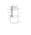
- FIG. 4 is a perspective view of the coil assembly.
- FIG. 5 is a side view of the second yoke.
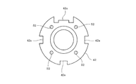
- FIG. 6 is a plan view of the coil assembly.
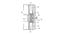
- FIG. 7 is a partial vertical cross-sectional view of a portion where a lead wire is led out in the coil assembly.
- FIG. 8 is a partial vertical cross-sectional view of a portion from which a lead wire is led out in a state where the coil assembly is accommodated in the cylinder.
- FIG. 9 is a partial vertical cross-sectional view of the main part of the coil assembly according to the second embodiment.
- FIG. 10 is a view corresponding to FIG. 3 according to the third embodiment.
- 1 is an outer box
- 2 is a laundry doorway
- 4 is an operation panel
- 6 is a water tank
- 7 is a suspension
- 10 is a drum
- 21 is a damper
- 22 is a cylinder
- 23 is a shaft
- 33 is an upper bracket
- 34 is a bearing
- 36 is a bearing
- 37 is a coil assembly
- 38 is a through hole
- 39 is a first yoke
- 39a is a recess (engaged portion)
- 40 is a first coil
- 41 is a first bobbin
- 41a is a convex part (engagement part)
- 42 is a second yoke
- 42a is a through hole (engaged part)
- 43 is a second coil
- 44 is a second bobbin
- 44a is a convex part (engagement part) )
- 45 is a third yoke
- 46 is resin
- 47 is an end plate
- FIG. 2 shows the overall structure of the drum type washing machine according to the first embodiment, and the outer box 1 is an outer shell.
- a laundry entrance / exit 2 is formed at the center of the front side of the outer box 1 (right side in FIG. 2), and a door 3 for opening and closing the entrance / exit 2 is provided.
- an operation panel 4 is provided at the upper part of the front surface of the outer box 1, and a control device 5 for operation control is provided on the back side (inside the outer box 1).
- a water tank (tank) 6 is disposed inside the outer box 1.
- the aquarium 6 has a horizontal cylindrical shape in which the axial direction is front and rear (right and left in FIG. 2), and is tilted forward by a pair of left and right (only one shown) suspensions 7 on the bottom plate 1a of the outer box 1. It is elastically supported in the shape. The detailed structure of the suspension 7 will be described later.
- a motor 8 is attached to the back of the water tank 6.
- the motor 8 is composed of, for example, a direct current brushless motor, and is an outer rotor type.
- a rotating shaft (not shown) attached to the center portion of the rotor 8a is connected to the inside of the water tank 6 via the bearing bracket 9. Is inserted.
- a drum 10 is disposed inside the water tank 6.
- This drum 10 also has a horizontal cylindrical shape with the front and rear being axially attached. By attaching it to the tip of the rotating shaft of the motor 8 at the center of the rear part, the drum 10 has a forwardly inclined shape coaxial with the water tank 6. I support it. As a result, the drum 10 is rotated by the motor 8. Therefore, the drum 10 is a rotating tank, and the motor 8 functions as a driving device that rotates the drum 10.
- a large number of small holes 11 are formed in the circumferential side portion (body portion) of the drum 10 over the entire area (only a part is shown).
- Each of the drum 10 and the water tub 6 has openings 12 and 13 on the front surface thereof, and the laundry entrance 2 is connected to the opening 13 of the water tub 6 through an annular bellows 14. .
- the laundry entrance / exit 2 is connected to the inside of the drum 10 via the bellows 14, the opening 13 of the water tub 6, and the opening 12 of the drum 10.
- a drain pipe 16 is connected to the rear part of the bottom, which is the lowest part of the water tank 6, via a drain valve 15.
- a drying device 17 is disposed above and in front of the back of the water tank 6.
- the drying device 17 includes a dehumidifier 18, a blower (blower device) 19, and a heater (heating device) 20.
- the drying device 17 dehydrates the air in the water tub 6 and then heats it to dry the laundry by circulating it back into the water tub 6.
- the suspension 7 has a damper 21, and the damper 21 includes a cylinder (outer cylinder) 22 and a shaft 23 as main members as shown in FIG. 1.
- the cylinder 22 has a connecting member 24 at its upper end, and the connecting member 24 is passed through the mounting plate 25 of the water tank 6 from below as shown in FIG. It is attached to the water tank 6 by being fastened with a nut 27.
- the shaft 23 has a connecting portion 23a at the lower end, and the connecting portion 23a is passed through the mounting plate 28 of the bottom plate 1a of the outer box 1 from above as shown in FIG. It is attached to the bottom plate 1a of the outer box 1 by fastening with a nut 30 via 29 or the like.
- a spring receiving seat 31 is fitted and fixed to a lower portion of the shaft 23 that protrudes downward from the outside of the cylinder 22.
- a coil spring 32 comprising a compression coil spring surrounding the shaft 23 is mounted between the spring seat 31 and the lower end of the cylinder 22.
- the spring receiving seat 31 is supported by a hook-shaped spring receiving portion 23b provided on the shaft 23 and is prevented from coming off.
- An annular upper bracket 33 is accommodated in an intermediate portion inside the cylinder 22, and a groove 33 a is formed in the outer peripheral portion of the upper bracket 33, and the groove 33 a in the peripheral wall portion of the cylinder 22 is formed in the groove 33 a.
- the upper bracket 33 is fixed to the cylinder 22 by caulking the corresponding part inward.
- a bearing 34 that supports the shaft 23 so as to be movable in the vertical direction is housed and fixed to the inner peripheral portion of the upper bracket 33.
- the bearing 34 is made of, for example, sintered oil-impregnated metal.
- An annular lower bracket 35 is accommodated in the lower end portion inside the cylinder 22, and a groove 35 a is formed in the outer peripheral portion of the lower bracket 35, and the groove 35 a in the peripheral wall portion of the cylinder 22 is formed in the groove 35 a.
- the lower bracket 35 is fixed by caulking the corresponding part inward.
- a bearing 36 that supports the shaft 23 so as to be movable in the vertical direction is housed and fixed to the inner peripheral portion of the lower bracket 35.
- the bearing 36 is made of, for example, sintered oil-impregnated metal.
- a cylindrical portion 35 b protruding downward from the lower surface portion of the lower bracket 35 in FIG. 1 protrudes downward through an opening formed in the lower end surface portion of the cylinder 22.
- a coil assembly 37 is accommodated in a portion between the upper bracket 33 and the lower bracket 35 inside the cylinder 22, and the coil assembly 37 is sandwiched and fixed between the upper bracket 33 and the lower bracket 35. Yes.
- the coil assembly 37 is formed with a through hole 38 through which the shaft 23 is inserted and movable in the vertical direction. The detailed structure of the coil assembly 37 will be described with reference to FIGS.
- the coil assembly 37 includes a first yoke 39, a first bobbin 41 around which the first coil 40 is wound, a second yoke 42, and a second coil 43.
- a second bobbin 44 and a third yoke 45 are provided.
- the coils 40 and 43, the bobbins 41 and 44, and the yokes 39, 42, and 45 are molded with resin 46 (insert molding) (see FIGS. 3 and 4).
- An annular recess 49 is formed on the upper side surface of the first yoke 39 in FIG. 3, and the seal member 50 is press-fitted and fixed in the annular recess 49.
- the seal member 50 protrudes from the side surface of the first yoke 39, and the protruding portion of the seal member 50 is accommodated in an annular recess 51 formed on the lower surface of the upper bracket 33 in FIG. It has become.
- the convex portion 47a of the end plate 47 of the bobbin 41 and the convex portion 47a of the end plate 47 of the second bobbin 44 are configured to be fitted (engaged).
- a concave portion 48 (engaged portion) into which the convex portion 47a of the end plate 47 is fitted (engaged). ) Is formed.
- An annular recess 53 is formed on the lower surface of the third yoke 45 in FIG. 3, and a seal member 54 is press-fitted and fixed in the annular recess 53.
- the seal member 54 protrudes from the lower surface of the third yoke 45, and the protruding portion of the seal member 54 is accommodated in an annular recess 55 formed on the upper surface of the lower bracket 35 in FIG. It has become.
- the convex portion 47 a of the end plate 47 of the first bobbin 41 is fitted into the concave portion 48 of the first yoke 39, and the first yoke 39 has a first surface on the side surface.
- An annular convex portion 47b protruding from the inner peripheral portion of the end plate 47 of the bobbin 41 is brought into contact.
- the convex portions 47 a of the end plates 47 of the first bobbin 41 and the second bobbin 44 are fitted into the through holes 52 of the second yoke 42, and the first yoke 42 is provided on both side surfaces of the first yoke 42.
- annular convex portion 47b protruding from the inner peripheral portion of each end plate 47 of the bobbin 41 and the second bobbin 44 is brought into contact. Further, the convex portion 47 a of the end plate 47 of the second bobbin 44 is fitted into the concave portion 48 of the third yoke 45, and the inner periphery of the end plate 47 of the second bobbin 44 is fitted to the side surface of the third yoke 45. An annular protrusion 47b protruding from the portion is brought into contact.
- the yokes 39, 42, 45 and the bobbins (coils 40, 43) 41, 44 assembled as described above are passed through a round bar (not shown) provided at the position of the shaft 23 and adapted to the inner diameter of the yoke. Then, in a state where the centers of the respective parts are aligned and positioned so that the resin does not go around, they are accommodated in a mold (not shown) and molded with the resin 46 (insert molding). Thus, the coils 40 and 43, the bobbins 41 and 44, and the yokes 39, 42, and 45 are fixed by the resin 46. The round bar is removed after molding.
- the resin 46 for example, a thermoplastic resin (nylon, PBT, PET, PP, or the like) is used.
- the resin 46 covers the outer peripheral portions of the coils 40, 43 and the bobbins 41, 44, and covers approximately the lower half of the outer peripheral portion of the first yoke 39 in the axial direction.
- 3 of the outer periphery of the three yokes 45 is covered with about the upper half in the axial direction.
- the round inner surface prevents the resin 46 from wrapping around, the inner surface of the yoke is particularly maintained as a metal surface.
- the groove 42a located at the top in FIG. 5 is formed wider and wider than the other three grooves 42a.
- the resin 46 is filled in a ring-shaped groove 45 a formed in the outer peripheral portion of the third yoke 45, and a gap between the side surface of the third yoke 45 and the end plate 47 of the second bobbin 44. Is filled.
- the outer peripheral part of the mold part of the resin 46 has a cylindrical shape, and the mold part of the resin 46 forms an inner cylinder (inner cylinder).
- the inner diameter dimension of the through hole 38 (hole into which the shaft 23 is inserted) of the resin-molded coil assembly 37 as described above will be described.
- the inner diameters of the three yokes 39, 42, 45 are set to the same dimension, and a gap of, for example, about 0.4 mm is formed between the outer periphery of the shaft 23.
- the inner diameters of the two bobbins 41 and 44 are set to the same size and slightly larger than the inner diameters of the three yokes 39, 42, and 45. For example, a gap of about 1.0 mm is formed.
- the inner peripheral portion and the outer peripheral portion of the second yoke 42 are communicated with the central portion of the upper large groove 42 a in FIG. 5 in the second yoke 42.
- the through-hole 42b is formed in.
- a pipe 55 having a thread portion formed on the outer periphery is fastened and fixed in the through hole 42b. This pipe 55 is a member for filling and injecting a magnetorheological fluid described later.
- the two coils 40 and 43 are connected in series, and lead wires 56 and 56 are connected to both terminals. As shown in FIG. 4, these lead wires 56, 56 are led out to the outside from the large groove 42 a portion of the second yoke 42 in the upper portion in FIG. 5 of the resin molding (molding) portion. In this case, as shown in FIG. 7, a rubber or resin support part 57 for supporting the lead wires 56, 56 is disposed in the large groove 42 a of the second yoke 42 and molded with the resin 46. ing. A T-shaped support hole 57a is formed in the support component 57, and lead wires 56 are accommodated in the support hole 57a.
- the support component 57 is divided into two along the support hole 57a in order to accommodate the lead wires 56, 56 in the support hole 57a.
- the lead wires 56 and 56 are led from the coils 40 and 43 through the guide grooves (not shown) formed in the end plates 47 and 47 of the bobbins 41 and 44 into the support holes 57a of the support component 57.
- a substantially circular recess 58 is formed in a portion corresponding to the through hole 42b (groove 42a) of the second yoke 42 in the mold portion of the resin 46.
- An accommodation groove 59 for accommodating the lead wires 56 is formed so as to extend upward from the recess 58.
- a housing groove 39 b for housing the lead wires 56 is formed in a portion corresponding to the housing groove 59 in the outer peripheral portion of the first yoke 39.
- the lead wire 56 led out from the resin mold portion (support component 57) is connected to the recess 58, the accommodation groove 59 and the accommodation groove.
- the lead wire 56 is accommodated in 39 b so that it does not protrude from the outer peripheral surface of the coil assembly 37.
- the coil assembly 37 in which the lead wire 56 is treated as described above is accommodated in the cylinder 22 from above.
- the coil assembly 37 is accommodated in the cylinder 22 so that the recess 58 of the coil assembly 37 and the hole 60 (see FIG. 8) formed in the peripheral wall portion of the cylinder 22 are aligned.
- the lead wires 56 and 56 are pulled out from the hole 60 of the cylinder 22, and the lead wires 56 and 56 are led out of the cylinder 22 through the hole 60.
- the bush 61 is fitted and fixed to the hole 60 of the cylinder 22.
- the lead wire 56 led out from the bush 61 is connected to a control circuit (control device 5) that controls energization of the coils 40 and 43.
- FIG. 1 shows a state before caulking.
- the shaft 23 before the spring seat 31 is attached is inserted into the cylinder 22 from above, and the opening of the upper bracket 33, the bearing 34, the seal member 50, the first yoke 39, the first bobbin 41 ( The first coil 40), the second yoke 42, the second bobbin 44 (second coil 43), the third yoke 45, the seal member 54, the bearing 36 and the opening of the lower bracket 35 are sequentially passed through.
- the cylinder 22 protrudes downward.
- the shaft 23 is supported by the bearings 34 and 36, and the bearing 34, the seal member 50, the first yoke 39, the first bobbin 41 (first coil 40), and the second yoke 42.
- the second bobbin 44 (second coil 43), the third yoke 45, the seal member 54, and the bearing 36 are relatively reciprocable in the axial direction.
- a retaining ring 62 for retaining is attached to an upper end portion of the shaft 23, and a hollow 63 is formed inside the cylinder 22 above the retaining ring 62.
- a spring receiving seat 31 is fitted and fixed to a lower portion of the shaft 23 located below the cylinder 22, and the shaft 23 is surrounded between the spring receiving seat 31 and the lower end of the cylinder 22.
- a coil spring 32 comprising a compression coil spring is attached.
- a magnetorheological fluid 64 is injected and filled between the shaft 23 and the bobbins 41 and 44 (coils 40 and 43) and between the shaft 23 and the yokes 39, 42 and 45 which are in the vicinity thereof. (See FIGS. 1 and 3).
- the magnetorheological fluid 64 is sealed by the seal members 50 and 54 so as not to leak.
- a tube (not shown) is connected to the pipe 55 with the bush 61 shown in FIG. 8 removed from the hole 60 in the peripheral wall portion of the cylinder 22.
- the magnetorheological fluid 64 is injected into the spaces through the tubes.
- the opening of the pipe 55 is sealed with a seal member (not shown) or the like, and then the bush 61 is attached to the hole 60 of the cylinder 22.
- the suspension 7 configured as described above is incorporated between the water tank 6 and the bottom plate 1a of the outer box 1 so that the water tank 26 is supported on the bottom plate 21a of the outer box 21 by vibration isolation.
- thermoplastic resin is used as the resin 46 for integrally forming the coils 40 and 43, the bobbins 41 and 44, and the yokes 39, 42, and 45, the adhesion is improved and cracks are generated. And mechanical strength can be improved. If a flame-retardant resin is used as the resin 46, the effect of preventing the spread of fire can be obtained even in the unlikely event.
- the grooves 39a and 45a are provided in the outer peripheral portions of the yokes 39 and 45, and the resin 46 is filled in the grooves 39a and 45a.
- the mechanical strength of the resin mold body (coil assembly 37) can be further increased.
- the lead wire 56 is supported by the resin support component 57 when the lead wire 56 connected to the terminals of the coils 40 and 43 is led out from the molded portion of the resin 46. Therefore, the strength of the lead-out portion of the lead wire 56 can be increased, and the lead wire 56 can be sufficiently protected.
- the lead wire 56 is protected by the resin bush 61 at the portion where the lead wire 56 is led out through the hole 60 formed in the cylinder 22. The damage can be prevented and the lead wire 56 can be sufficiently protected.
- the convex portions 47 a are provided on the side surfaces of the end plates 47 of the bobbins 41, 44, and the convex portions 47 a are engaged with the side surfaces of the yokes 39, 42, 45 facing the side surfaces of the end plates 47. Since the recess 48 and the through hole 52 are provided, the bobbins 41 and 44 and the yokes 39, 42 and 45 can be prevented from rotating and mechanically fixed.
- FIG. 9 shows a second embodiment of the present invention.
- symbol is attached
- the convex portions 47b and 39c are staggered on the side surface of the end plate 47 of the first bobbin 41 and the side surface of the first yoke 39 facing the side surface of the end plate 47, respectively.
- the labyrinth structure (leak prevention part) was formed.
- the configuration of the second embodiment other than that described above is the same as the configuration of the first embodiment. Therefore, in the second embodiment, substantially the same operational effects as in the first embodiment can be obtained.
- the convex portions 47b and 39c are staggered on the side surfaces of the end plates 47 of the bobbins 41 and 44 and the side surfaces of the yokes 39, 42 and 45 facing the side surfaces of the end plates 47, respectively. Since the labyrinth structure is formed, the magnetorheological fluid 64 can be more reliably prevented from leaking from the joint between the bobbins 41, 44 and the yokes 39, 42, 45.
- FIG. 10 shows a third embodiment of the present invention.
- symbol is attached
- the round bar of the molding die is used.
- the molding surface 65 of the resin 46 is provided by making the resin 46 wrap around the inner peripheral surfaces of the bobbins 41 and 44 so as to match the inner diameter of the yoke.
- the molding surface 65 of the resin 46 and the inner peripheral surfaces of the yokes 39, 42, 45 are substantially flush, that is, the inner diameter dimension of the molding surface 65 of the resin 46 and the yokes 39, 42, The inner diameters of the 45 inner peripheral surfaces are configured to be equal.
- thermoplastic resin is used as the resin 46.
- the present invention is not limited to this, and a thermosetting resin may be used.
- the convex portions 47a are formed on the end plates 47 of the bobbins 41, 44, and the concave portions 48 and the through holes 52 are formed on the yokes 39, 42, 45.
- , 44 may be formed with recesses and the yokes 39, 42, 45 may be formed with protrusions.
- the damper 21 may be provided upside down and connected to the outer case 1 on the cylinder 22 side and connected to the water tank 6 on the shaft 23 side.
- the damper according to the present invention is useful for a suspension that elastically supports a tank of a washing machine or a washing / drying machine.
Landscapes
- Engineering & Computer Science (AREA)
- General Engineering & Computer Science (AREA)
- Textile Engineering (AREA)
- Physics & Mathematics (AREA)
- Electromagnetism (AREA)
- Mechanical Engineering (AREA)
- Main Body Construction Of Washing Machines And Laundry Dryers (AREA)
- Fluid-Damping Devices (AREA)
- Electromagnets (AREA)
- Vehicle Body Suspensions (AREA)
Abstract
Priority Applications (4)
| Application Number | Priority Date | Filing Date | Title |
|---|---|---|---|
| EP11783294.9A EP2573248B1 (fr) | 2010-05-21 | 2011-01-14 | Amortisseur, lave-linge, et lave-linge/sèche-linge |
| KR1020127030456A KR101412935B1 (ko) | 2010-05-21 | 2011-01-14 | 댐퍼, 세탁기 및 세탁건조기 |
| CN201180025299.0A CN102906326B (zh) | 2010-05-21 | 2011-01-14 | 阻尼器、洗涤机及洗涤干燥机 |
| US13/681,566 US8851247B2 (en) | 2010-05-21 | 2012-11-20 | Damper, washing machine and washing/drying machine |
Applications Claiming Priority (2)
| Application Number | Priority Date | Filing Date | Title |
|---|---|---|---|
| JP2010117311A JP5127879B2 (ja) | 2010-05-21 | 2010-05-21 | 洗濯機用のダンパ |
| JP2010-117311 | 2010-05-21 |
Related Child Applications (1)
| Application Number | Title | Priority Date | Filing Date |
|---|---|---|---|
| US13/681,566 Continuation US8851247B2 (en) | 2010-05-21 | 2012-11-20 | Damper, washing machine and washing/drying machine |
Publications (1)
| Publication Number | Publication Date |
|---|---|
| WO2011145357A1 true WO2011145357A1 (fr) | 2011-11-24 |
Family
ID=44991475
Family Applications (1)
| Application Number | Title | Priority Date | Filing Date |
|---|---|---|---|
| PCT/JP2011/050539 Ceased WO2011145357A1 (fr) | 2010-05-21 | 2011-01-14 | Amortisseur, lave-linge, et lave-linge/sèche-linge |
Country Status (6)
| Country | Link |
|---|---|
| US (1) | US8851247B2 (fr) |
| EP (1) | EP2573248B1 (fr) |
| JP (1) | JP5127879B2 (fr) |
| KR (1) | KR101412935B1 (fr) |
| CN (1) | CN102906326B (fr) |
| WO (1) | WO2011145357A1 (fr) |
Cited By (1)
| Publication number | Priority date | Publication date | Assignee | Title |
|---|---|---|---|---|
| WO2013125123A1 (fr) * | 2012-02-24 | 2013-08-29 | カヤバ工業株式会社 | Amortisseur à fluide visqueux magnétique et procédé de fabrication d'un ensemble bobine utilisé pour celui-ci |
Families Citing this family (11)
| Publication number | Priority date | Publication date | Assignee | Title |
|---|---|---|---|---|
| KR101305874B1 (ko) * | 2012-04-18 | 2013-09-09 | 양동호 | 가변 강성형 진동 흡수 장치 |
| JP6042138B2 (ja) * | 2012-08-31 | 2016-12-14 | 東芝ライフスタイル株式会社 | 洗濯機用のダンパ |
| US9109650B2 (en) * | 2013-04-12 | 2015-08-18 | Washington State University | Linear MR-brake as a high force and low off-state friction actuator |
| DE102013217938A1 (de) * | 2013-09-09 | 2015-03-12 | Zf Friedrichshafen Ag | Schwingungsdämpfer für ein Kraftfahrzeug |
| JP2015132281A (ja) * | 2014-01-09 | 2015-07-23 | 不二ラテックス株式会社 | 電磁制御ダンパー |
| KR102402151B1 (ko) * | 2015-06-30 | 2022-05-27 | 엘지전자 주식회사 | 의류처리장치 |
| CN106917235B (zh) * | 2015-12-28 | 2019-09-17 | 青岛海尔智能技术研发有限公司 | 洗衣设备 |
| CN106917219B (zh) * | 2015-12-28 | 2020-06-02 | 青岛海尔智能技术研发有限公司 | 洗衣机 |
| JP7403395B2 (ja) * | 2020-06-24 | 2023-12-22 | 日立Astemo株式会社 | 電磁サスペンション |
| CN119053742A (zh) | 2022-07-13 | 2024-11-29 | 三星电子株式会社 | 衣物处理装置 |
| CN118829754A (zh) | 2022-07-13 | 2024-10-22 | 三星电子株式会社 | 洗衣机和用于控制该洗衣机的方法 |
Citations (6)
| Publication number | Priority date | Publication date | Assignee | Title |
|---|---|---|---|---|
| JPS63125243U (fr) * | 1987-02-06 | 1988-08-16 | ||
| US5492312A (en) * | 1995-04-17 | 1996-02-20 | Lord Corporation | Multi-degree of freedom magnetorheological devices and system for using same |
| JP2005502850A (ja) * | 2001-09-07 | 2005-01-27 | ボッシュ レックスロート アクチエンゲゼルシャフト | 磁気粘性流体ダンパ |
| JP2006057766A (ja) * | 2004-08-20 | 2006-03-02 | Showa Corp | Mr流体ダンパ |
| JP2007115835A (ja) * | 2005-10-19 | 2007-05-10 | Denso Corp | 樹脂モールド部品 |
| JP2008295906A (ja) * | 2007-06-04 | 2008-12-11 | Hitachi Appliances Inc | ドラム式洗濯機 |
Family Cites Families (32)
| Publication number | Priority date | Publication date | Assignee | Title |
|---|---|---|---|---|
| JPH0771556B2 (ja) | 1986-11-13 | 1995-08-02 | 株式会社東芝 | 超音波診断装置 |
| JPH0639093Y2 (ja) * | 1987-02-09 | 1994-10-12 | 株式会社ゼクセル | 燃料噴射ポンプ |
| US5284330A (en) | 1992-06-18 | 1994-02-08 | Lord Corporation | Magnetorheological fluid devices |
| JPH0821482A (ja) | 1994-07-04 | 1996-01-23 | Showa Electric Wire & Cable Co Ltd | 振動絶縁装置 |
| JPH0819687A (ja) | 1994-07-07 | 1996-01-23 | Hitachi Ltd | 全自動洗濯機の防振装置 |
| DE19717692A1 (de) | 1997-04-26 | 1998-10-29 | Schenck Ag Carl | Feder-Massen-Schwingkraftkoppler |
| JP3185098B2 (ja) * | 1997-07-17 | 2001-07-09 | 三明電機株式会社 | 電磁石 |
| US6202806B1 (en) | 1997-10-29 | 2001-03-20 | Lord Corporation | Controllable device having a matrix medium retaining structure |
| US6394239B1 (en) | 1997-10-29 | 2002-05-28 | Lord Corporation | Controllable medium device and apparatus utilizing same |
| US6340080B1 (en) | 1997-10-29 | 2002-01-22 | Lord Corporation | Apparatus including a matrix structure and apparatus |
| JPH10214715A (ja) | 1998-01-05 | 1998-08-11 | Kenji Masuda | 比例電磁石 |
| US6471018B1 (en) | 1998-11-20 | 2002-10-29 | Board Of Regents Of The University And Community College System On Behalf Of The University Of Nevada-Reno, The University Of Reno | Magneto-rheological fluid device |
| US6390253B1 (en) | 1999-10-05 | 2002-05-21 | Delphi Technologies, Inc. | Magneto-rheological damping apparatus |
| JP3709792B2 (ja) * | 2001-01-12 | 2005-10-26 | 株式会社デンソー | 電磁弁装置 |
| JP4705714B2 (ja) | 2000-10-20 | 2011-06-22 | オリエンタルモーター株式会社 | 簡易負荷装置 |
| US20020130002A1 (en) | 2001-03-15 | 2002-09-19 | Delphi Technologies, Inc. | Gas cup seal for magneto-rheological damper |
| US6497309B1 (en) | 2001-08-13 | 2002-12-24 | Delphi Technologies, Inc. | Magneto-rheological damper with an external coil |
| JP2004097388A (ja) * | 2002-09-06 | 2004-04-02 | Matsushita Electric Ind Co Ltd | ドラム式洗濯乾燥機 |
| JP2004278783A (ja) | 2003-02-28 | 2004-10-07 | Tokico Ltd | 電磁サスペンション装置 |
| US6883649B2 (en) | 2003-03-21 | 2005-04-26 | Delphi Technologies, Inc. | Closing system for a magneto-rheological damper |
| JP4712794B2 (ja) | 2004-03-25 | 2011-06-29 | ロード・コーポレーション | 回転槽洗濯機二元ダンパ・システム |
| DE102005032499B4 (de) | 2004-07-13 | 2009-10-22 | Lg Electronics Inc. | Dämpfer zur Vibrationsdämpfung und damit ausgerüstete Waschmaschine |
| JP2006230591A (ja) | 2005-02-23 | 2006-09-07 | Toshiba Corp | ドラム式洗濯機 |
| CA2637511C (fr) | 2006-02-09 | 2012-05-22 | Central Research Institute Of Electric Power Industry | Amortisseur a fluide |
| KR20080005743A (ko) | 2006-07-10 | 2008-01-15 | 볼보 컨스트럭션 이키프먼트 홀딩 스웨덴 에이비 | 유압실린더 내부 방청장치 |
| JP2008208885A (ja) | 2007-02-26 | 2008-09-11 | Univ Kanagawa | 粘性可変流体緩衝器 |
| JP4674601B2 (ja) | 2007-10-18 | 2011-04-20 | パナソニック株式会社 | ドラム式洗濯機 |
| JP2009133472A (ja) * | 2007-10-30 | 2009-06-18 | Honda Motor Co Ltd | 減衰力可変ダンパ |
| US20090151398A1 (en) | 2007-12-18 | 2009-06-18 | Bsh Home Appliances Corporation | Anti-vibration device |
| JP5127740B2 (ja) | 2009-02-13 | 2013-01-23 | 株式会社東芝 | 洗濯機 |
| CN101709761B (zh) | 2009-12-23 | 2011-07-06 | 重庆仪表材料研究所 | 一种单出杆磁流变阻尼器 |
| CN102770594B (zh) * | 2010-02-24 | 2015-03-25 | 株式会社东芝 | 减震器、洗涤机以及洗涤干燥机 |
-
2010
- 2010-05-21 JP JP2010117311A patent/JP5127879B2/ja active Active
-
2011
- 2011-01-14 WO PCT/JP2011/050539 patent/WO2011145357A1/fr not_active Ceased
- 2011-01-14 CN CN201180025299.0A patent/CN102906326B/zh active Active
- 2011-01-14 EP EP11783294.9A patent/EP2573248B1/fr active Active
- 2011-01-14 KR KR1020127030456A patent/KR101412935B1/ko active Active
-
2012
- 2012-11-20 US US13/681,566 patent/US8851247B2/en active Active
Patent Citations (6)
| Publication number | Priority date | Publication date | Assignee | Title |
|---|---|---|---|---|
| JPS63125243U (fr) * | 1987-02-06 | 1988-08-16 | ||
| US5492312A (en) * | 1995-04-17 | 1996-02-20 | Lord Corporation | Multi-degree of freedom magnetorheological devices and system for using same |
| JP2005502850A (ja) * | 2001-09-07 | 2005-01-27 | ボッシュ レックスロート アクチエンゲゼルシャフト | 磁気粘性流体ダンパ |
| JP2006057766A (ja) * | 2004-08-20 | 2006-03-02 | Showa Corp | Mr流体ダンパ |
| JP2007115835A (ja) * | 2005-10-19 | 2007-05-10 | Denso Corp | 樹脂モールド部品 |
| JP2008295906A (ja) * | 2007-06-04 | 2008-12-11 | Hitachi Appliances Inc | ドラム式洗濯機 |
Cited By (8)
| Publication number | Priority date | Publication date | Assignee | Title |
|---|---|---|---|---|
| WO2013125123A1 (fr) * | 2012-02-24 | 2013-08-29 | カヤバ工業株式会社 | Amortisseur à fluide visqueux magnétique et procédé de fabrication d'un ensemble bobine utilisé pour celui-ci |
| JP2013174309A (ja) * | 2012-02-24 | 2013-09-05 | Kyb Co Ltd | 磁気粘性流体緩衝器及びそれに用いられるコイルアセンブリの製造方法 |
| KR20140124424A (ko) * | 2012-02-24 | 2014-10-24 | 카야바 고교 가부시기가이샤 | 자기 점성 유체 완충기 및 그것에 사용되는 코일 어셈블리의 제조 방법 |
| CN104136797A (zh) * | 2012-02-24 | 2014-11-05 | 萱场工业株式会社 | 磁粘滞性流体缓冲器和在该磁粘滞性流体缓冲器中使用的线圈组件的制造方法 |
| EP2818752A4 (fr) * | 2012-02-24 | 2015-12-02 | Kayaba Industry Co Ltd | Amortisseur à fluide visqueux magnétique et procédé de fabrication d'un ensemble bobine utilisé pour celui-ci |
| CN104136797B (zh) * | 2012-02-24 | 2016-01-20 | 萱场工业株式会社 | 磁粘滞性流体缓冲器和在该磁粘滞性流体缓冲器中使用的线圈组件的制造方法 |
| KR101598745B1 (ko) * | 2012-02-24 | 2016-02-29 | 케이와이비 가부시키가이샤 | 자기 점성 유체 완충기 및 그것에 사용되는 코일 어셈블리의 제조 방법 |
| US9347514B2 (en) | 2012-02-24 | 2016-05-24 | Kyb Corporation | Magnetic viscous fluid damper and manufacturing method of coil assembly used therefor |
Also Published As
| Publication number | Publication date |
|---|---|
| KR101412935B1 (ko) | 2014-07-03 |
| CN102906326B (zh) | 2015-05-06 |
| EP2573248A4 (fr) | 2017-11-15 |
| JP2011240079A (ja) | 2011-12-01 |
| EP2573248B1 (fr) | 2020-06-17 |
| US8851247B2 (en) | 2014-10-07 |
| US20130081433A1 (en) | 2013-04-04 |
| CN102906326A (zh) | 2013-01-30 |
| EP2573248A1 (fr) | 2013-03-27 |
| JP5127879B2 (ja) | 2013-01-23 |
| KR20130028107A (ko) | 2013-03-18 |
Similar Documents
| Publication | Publication Date | Title |
|---|---|---|
| JP5127879B2 (ja) | 洗濯機用のダンパ | |
| JP5426278B2 (ja) | ドラム式洗濯機 | |
| KR101411148B1 (ko) | 댐퍼, 세탁기 및 세탁 건조기 | |
| JP5773805B2 (ja) | 洗濯機 | |
| JP6042138B2 (ja) | 洗濯機用のダンパ | |
| JP5854587B2 (ja) | 洗濯機 | |
| JP5349424B2 (ja) | 洗濯機 | |
| KR101280082B1 (ko) | 세탁기 | |
| JP5330345B2 (ja) | 洗濯機 | |
| JP5489351B2 (ja) | 洗濯機 | |
| KR101302247B1 (ko) | 세탁기 | |
| JP5931356B2 (ja) | 洗濯機 | |
| JP5127894B2 (ja) | 洗濯機用のダンパ | |
| KR101341759B1 (ko) | 드럼식 세탁기 | |
| JP5330343B2 (ja) | 洗濯機 |
Legal Events
| Date | Code | Title | Description |
|---|---|---|---|
| WWE | Wipo information: entry into national phase |
Ref document number: 201180025299.0 Country of ref document: CN |
|
| 121 | Ep: the epo has been informed by wipo that ep was designated in this application |
Ref document number: 11783294 Country of ref document: EP Kind code of ref document: A1 |
|
| WWE | Wipo information: entry into national phase |
Ref document number: 2011783294 Country of ref document: EP |
|
| ENP | Entry into the national phase |
Ref document number: 20127030456 Country of ref document: KR Kind code of ref document: A |
|
| NENP | Non-entry into the national phase |
Ref country code: DE |