WO2011148978A1 - 誘導モータの回転子及びそれを用いた誘導モータ - Google Patents
誘導モータの回転子及びそれを用いた誘導モータ Download PDFInfo
- Publication number
- WO2011148978A1 WO2011148978A1 PCT/JP2011/061989 JP2011061989W WO2011148978A1 WO 2011148978 A1 WO2011148978 A1 WO 2011148978A1 JP 2011061989 W JP2011061989 W JP 2011061989W WO 2011148978 A1 WO2011148978 A1 WO 2011148978A1
- Authority
- WO
- WIPO (PCT)
- Prior art keywords
- conductor
- rotor
- induction motor
- carbon nanotube
- stator
- Prior art date
- Legal status (The legal status is an assumption and is not a legal conclusion. Google has not performed a legal analysis and makes no representation as to the accuracy of the status listed.)
- Ceased
Links
Images
Classifications
-
- H—ELECTRICITY
- H02—GENERATION; CONVERSION OR DISTRIBUTION OF ELECTRIC POWER
- H02K—DYNAMO-ELECTRIC MACHINES
- H02K3/00—Details of windings
- H02K3/02—Windings characterised by the conductor material
-
- H—ELECTRICITY
- H02—GENERATION; CONVERSION OR DISTRIBUTION OF ELECTRIC POWER
- H02K—DYNAMO-ELECTRIC MACHINES
- H02K17/00—Asynchronous induction motors; Asynchronous induction generators
- H02K17/02—Asynchronous induction motors
- H02K17/16—Asynchronous induction motors having rotors with internally short-circuited windings, e.g. cage rotors
- H02K17/168—Asynchronous induction motors having rotors with internally short-circuited windings, e.g. cage rotors having single-cage rotors
-
- B—PERFORMING OPERATIONS; TRANSPORTING
- B82—NANOTECHNOLOGY
- B82Y—SPECIFIC USES OR APPLICATIONS OF NANOSTRUCTURES; MEASUREMENT OR ANALYSIS OF NANOSTRUCTURES; MANUFACTURE OR TREATMENT OF NANOSTRUCTURES
- B82Y99/00—Subject matter not provided for in other groups of this subclass
-
- Y—GENERAL TAGGING OF NEW TECHNOLOGICAL DEVELOPMENTS; GENERAL TAGGING OF CROSS-SECTIONAL TECHNOLOGIES SPANNING OVER SEVERAL SECTIONS OF THE IPC; TECHNICAL SUBJECTS COVERED BY FORMER USPC CROSS-REFERENCE ART COLLECTIONS [XRACs] AND DIGESTS
- Y10—TECHNICAL SUBJECTS COVERED BY FORMER USPC
- Y10S—TECHNICAL SUBJECTS COVERED BY FORMER USPC CROSS-REFERENCE ART COLLECTIONS [XRACs] AND DIGESTS
- Y10S977/00—Nanotechnology
- Y10S977/902—Specified use of nanostructure
- Y10S977/932—Specified use of nanostructure for electronic or optoelectronic application
Definitions
- the present invention relates to an induction motor, and more particularly to a rotor of an induction motor that rotates by electromagnetic induction in response to a magnetic force generated by a stator and an induction motor using the same.
- the induction motors disclosed in Patent Documents 1 and 2 are a stator that generates a rotating magnetic field inside the hollow, and is rotatably arranged inside the hollow of the stator, and receives the magnetic force of the magnetic field generated by the stator. It is mainly composed of a rotating rotor.
- the stator is composed of a stator core having a hollow portion inside and a stator coil wound around the inner peripheral portion of the stator core, and a magnetic field is generated inside the hollow by passing an electric current through the stator coil. It is formed.
- the rotor is formed by assembling an iron core part and a squirrel-cage conductor part integrally with a rotating shaft.
- the cage-shaped conductor portion is formed by a pair of annular conductors (end rings) and a plurality of rod-shaped conductors (conductor bars) connected between the pair of annular conductors.
- a rotor is rotatably disposed inside the hollow of the stator, and a magnetic field generated by the stator coil is applied to the rotor by energizing the stator coil, and an electric current (eddy current) is applied to the rod-shaped conductor by this magnetic field.
- the electromagnetic force is generated in the rotor by the current generated in the rod-shaped conductor and the magnetic field from the stator.
- the rotor rotates by the electromagnetic force generated in the rotor. In this case, when the induction motor is started, a high-frequency current flows through the rod-shaped conductor by the magnetic field formed by the stator.
- Such induction motors are simpler and more robust in structure than DC motors and synchronous motors using permanent magnets, and do not require complex control, so they are easy to use, relatively inexpensive, and constant speed. There is an advantage that it can cope with variable speed.
- JP-A-6-165451 Japanese Patent Laid-Open No. 10-32966
- the induction motor has a problem in that the efficiency is poor because the shaft output of the rotor is reduced due to heat loss with respect to the input power.
- the present invention relates to an induction motor rotor that can reduce the heat loss of the induction motor and reduce the size by reducing the electrical resistance of the rotor surface in the rotor of the induction motor, and the same.
- An object is to provide an induction motor.
- a first aspect of the present invention is a rotor of an induction motor that is rotatably arranged inside a hollow of a stator of an induction motor and rotates by receiving a magnetic force from a magnetic field formed in the hollow by the stator.
- a pair of annular conductors and a plurality of rod-shaped conductors connected between the pair of annular conductors to form a cage shape with the pair of annular conductors, the annular conductor and the rod-shaped conductor,
- the gist of the invention is that it is a rotor of an induction motor formed of a composite material composed of a conductive core conductor and a carbon nanotube structure that adheres to the outer periphery of the core conductor in an electrical contact state.
- the annular motor and the rod-shaped conductor of the rotor of the induction motor are formed of the composite material in which the carbon nanotube structure is attached to the outer periphery of the core conductor in an electrical contact state.
- the core conductor may be a copper rod or an aluminum rod.
- the diameter of the core conductor is reduced by using copper or aluminum, which is generally used as a rod-shaped conductor in the induction motor, as the core conductor and attaching the carbon nanotube structure to the outer periphery thereof.
- copper or aluminum which is generally used as a rod-shaped conductor in the induction motor, as the core conductor and attaching the carbon nanotube structure to the outer periphery thereof.
- the carbon nanotube structure is formed of an aggregate of a plurality of carbon nanotubes, and a conductor made of nano metal particles is attached to the surface of each carbon nanotube, the inside of each carbon nanotube, and the carbon nanotube.
- the wettability improving treatment may be performed, and the outer periphery of the core conductor may be attached in a braided shape and impregnated or compacted with aluminum.
- the carbon nanotube structure is formed of an aggregate of a plurality of carbon nanotubes, and a conductor made of nano metal particles is attached to the surface of each carbon nanotube, the inside of each carbon nanotube, and the carbon nanotube.
- the wettability improving treatment may be performed, and the aluminum may be impregnated or compacted and adhered to the outer periphery of the core conductor by horizontal winding.
- electrons can easily enter the carbon nanotubes, and the electrons flow at a high speed, so that the conductivity can be improved, and the electrons can easily enter from one carbon nanotube to another carbon nanotube. Since electrons can flow at high speed, the conductivity can be further improved.
- a stator that forms a magnetic field in a hollow interior, and a stator that is rotatably disposed in the hollow interior of the stator and rotates by receiving a magnetic force from the magnetic field formed by the stator.
- a rotor, and the rotor includes a pair of annular conductors and a plurality of rod-shaped conductors connected between the pair of annular conductors, the pair of annular conductors and the plurality of rod-shaped conductors
- the annular conductor and the rod-shaped conductor are each formed of a composite material composed of a conductive core conductor and a carbon nanotube structure that adheres to the outer periphery of the core conductor in an electrical contact state.
- the main point is that the induction motor is used.
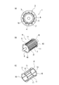
- FIG. 1 shows an induction motor
- FIG. 1 (a) is a sectional view thereof
- FIG. 1 (b) is a perspective view showing a rotor
- FIG. 1 (c) is a perspective view showing a cage of the rotor.
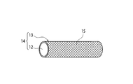
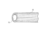
- FIG. 2 is a perspective view showing a composite material in which spun carbon nanotubes are attached in a braided shape to the surface of a copper bar.
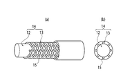
- FIG. 3 shows a composite material in which spun carbon nanotubes are attached to the surface of a copper bar and impregnated with aluminum
- FIG. 3 (a) is a perspective view thereof
- FIG. 3 (b) is a sectional view thereof.
- FIG. 1 shows an induction motor
- FIG. 1 (a) is a sectional view thereof
- FIG. 1 (b) is a perspective view showing a rotor
- FIG. 1 (c) is a perspective view showing a cage of the rotor.
- FIG. 2 is a perspective view showing a composite material in which spun
- FIG. 4 is an explanatory view showing a state in which a conductor (nano metal particle) is attached to the carbon nanotube.
- FIG. 5 is a perspective view illustrating a composite material in which the spun carbon nanotubes are attached in a horizontal winding shape on the surface of a copper bar material according to a first modification.
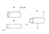
- FIG. 6 shows a second modification, showing a composite material in which a spun carbon nanotube impregnated with aluminum is adhered to the surface of a copper bar
- FIG. 6 (a) is a composite in which aluminum is impregnated with carbon nanotubes.
- FIG. 6B is a perspective view showing a copper bar
- FIG. 6C is a perspective view showing a state in which the copper bar is press-fitted into the hollow inside of the composite material.
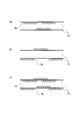
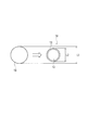
- FIG. 7 is a cross-sectional view showing a comparison between the diameters of a copper bar and a composite material in which carbon nanotubes are attached to the surface of a copper bar.
- an induction motor 1 includes a stator 2 that generates a rotating magnetic field, and a rotor 2 that is rotatably disposed within a hollow interior 3 of the stator 2, and electromagnetic waves generated by the rotating magnetic field generated by the stator 2. It is formed with a rotor 4 that rotates in response to force.
- the stator 2 is composed of a stator core 6 having a hollow portion 5 inside a columnar shape, and a stator coil (not shown) wound around an inner peripheral portion of the stator core 6.
- a magnetic field is formed in the hollow interior 3 by passing an electric current.
- a high-frequency induced current flows through the rotor 4 by the magnetic force from the magnetic field, and a rotational force is generated by the induced current and the magnetic field generated by the stator 2, and the rotor 4 rotates in the hollow interior 3.
- the rotor 4 is formed by integrally assembling a core portion 7 and a cage-shaped conductor portion 8 to a rotation shaft (output shaft) 9 as shown in FIG.
- the cage-shaped conductor portion 8 includes a pair of annular conductors (hereinafter referred to as “end rings”) 10 and 10, and a plurality of conductors connected between the pair of end rings 10 and 10.
- the rod-shaped conductor (hereinafter referred to as “conductor bar”) 11 is formed.
- the end rings 10, 10 and the conductor bar 11 of the present embodiment are attached to the conductive core conductor 12 and the outer periphery of the core conductor 12 in an electrical contact state.
- CNT Carbon nanotube
- the core conductor 12 is formed of a copper core material formed of a copper rod body or an aluminum core material formed of an aluminum rod body, and has high conductivity, high current density resistance, and high thermal conductivity in any material. It is made of a material with excellent properties. In the example of this embodiment, it is formed of a copper core material made of a copper rod. A carbon nanotube structure 13 made of CNTs 15 formed in a braided shape is attached to the outer periphery of the copper core material, and in this state, impregnated with aluminum.
- the CNT 15 is a structure in which a hexagonal shape in which six carbons are bonded is formed in a cylindrical shape in a state where it is combined with another hexagon, and a fiber CNT is formed from the plurality of CNTs 15. Then, the entangled fibers CNT are stretched and aligned from an aggregate of a plurality of fibers CNTs, and twisted to form a uniform and constant thread shape, thereby forming a spun CNT.
- the fiber CNT, the aggregate of the fiber CNT, and the spun CNT are referred to as the CNT structure 13.
- the composite material 14 according to the present embodiment has a metal nanoparticle (conductor) in the surface of the CNTs 15, inside the CNTs 15, and between the CNTs 15. Is applied on the nanoscale, so that wettability improving treatment for improving so-called wettability is performed.
- FIG. 1 As a method of this wettability improving treatment, a technique of “an assembly of carbon and non-carbon and an manufacturing method thereof” described in JP-T-2009-535294, which has already been filed, is used in FIG.
- the non-carbon material Fe, Si, Co, Cr, Mn, Mo, Nb, Ta, Th, Ti, U, V, Y, the surface of the CNT 15, the inside of the CNT 15, and the CNT 15 between the CNT 15, Zr
- the CNTs 15 become strong bonds (covalent bonds) by the metal nanoparticles 18, and the resistance between the metal nanoparticles 18 can be reduced, so that the resistance between the CNTs 15 becomes low.
- the metal nanoparticles 18 attached to the surface of the CNT 15 make it easier for electrons to pass through the inside of the CNT 15 through the metal nanoparticles 18, and the electrons more easily flow through the metal nanoparticles 18 attached to the inside of the CNT 15. As a result, high conductivity can be obtained.
- the entangled fiber CNTs are stretched and aligned from the aggregate of the fiber CNTs formed from such CNTs 15 and twisted to form a spun CNT formed into a uniform and constant thread shape on the surface of the copper core (outer periphery) ) In a braided shape.
- the CNT structure 13 is impregnated with aluminum 16 in a state where the braided CNT structure 13 is attached to the outer periphery of the copper core material that is the core conductor 12.
- the spinning CNT is impregnated with the aluminum 16 by a vacuum pressure impregnation method.
- the technology of “composite material and manufacturing method thereof” described in Japanese Patent Application Laid-Open No. 2001-107203, the technology of “composite material” described in Japanese Patent Application Laid-Open No. 2002-59257, Spinning CNT (CNT structure 13) can be impregnated with aluminum 16 by using the technique of “composite material and manufacturing method thereof” described in JP-A-2002-194515.
- a composite material 14 including the core conductor 12 and the CNT structure 13 is formed, and the end ring 10 and the conductor bar 11 of the induction motor 1 are formed by the composite material 14.
- the CNT structure 13 is attached to the outer periphery of the core conductor 12 made of a copper core material in a braided shape to form a braid.
- a CNT structure 13 is attached to the outer periphery of a core conductor 12 made of a core material in a horizontal winding shape.
- the aluminum 16 is impregnated by the vacuum pressure impregnation method as in the above embodiment.
- the CNT structure 13 is attached to the outer periphery of the core conductor 12, and then the aluminum 16 is impregnated.
- the CNT 15 has the same wettability as in the above embodiment.
- a composite material 17 in which aluminum 16 is impregnated with an assembly of CNT 15 fibers by a vacuum pressure impregnation method similar to that of the above-described embodiment in a state of being subjected to the improvement treatment is cylindrical (as shown in FIG. 6A).
- the core conductor 12 made of a copper core material shown in FIG. 6B is formed in the cylindrical composite material 17 formed into a tube shape and the aggregate of CNT fibers impregnated with aluminum 16 in FIG.
- the composite material 14 including the core conductor 12 and the composite material 17 is formed by press-fitting as shown in c).
- the core conductor 12 is press-fitted into the composite material 17 of the cylindrical CNT structure 13 impregnated with aluminum 16, but the inside of the cylindrical composite material 17 is swallowed.
- the inner surface of the composite material 17 of the cylindrical CNT structure 13 impregnated with aluminum 16 may be brought into close contact with the surface of the copper core material by squeezing.
- the composite material 14 including the conductive core conductor 12 and the CNT structure 13 attached to the outer periphery of the core conductor 12 in an electrical contact state By forming the end rings 10, 10 and the conductor bar 11, even if a high-frequency current generated by electromagnetic induction flows on the surface of the end rings 10, 10, and the conductor bar 11, from the CNT 15 having high conductivity on the surface side. Since the CNT structure 13 to be attached is attached, the resistance can be reduced.
- the electrical resistance of the surface can be reduced, the heat loss is reduced because the amount of heat generated is small even if the high frequency current is concentrated on the surface side due to the skin effect.
- the amount of heat generation can be reduced and heat dissipation is good, so it is possible to reduce or eliminate the heat-dissipating fins conventionally required in induction motors, and thus the size of induction motors can be reduced. For example, when it is used for in-vehicle use, the required mounting space can be reduced.
- it is possible to reduce the weight by reducing the size it is possible to contribute to reducing the weight of the vehicle when it is used in a vehicle.
- the CNT structure 13 is lighter than other conductors (aluminum and copper), when the copper core material is used, if the required diameter of the conductor bar 11 or the end ring 10 is the same, it adheres to the outer periphery. Since the diameter of the copper core material can be reduced by the amount of the CNT structure 13 to be performed, the weight of the entire induction motor can be reduced. Further, as shown in FIG. 7, it is formed of the composite material 14 of this embodiment having the same conductivity as that of the end ring 10 and the conductor bar 11 by the copper core material 19 that has been set to the required diameter L1 in the past. In this case, the diameter L2 can be made smaller than L1.
- the electrical contact between the CNT structure 13 and the copper core material can be remarkably improved. It can be reduced and a composite material with good conductivity can be obtained.
- the CNT structure 13 is formed in a cylindrical shape, but may be formed in a cylindrical shape other than the cylindrical shape.
- the core conductor 12 is formed with the copper core material which consists of a copper rod, and the example which impregnated or compacted aluminum as a conductive metal to CNT15 was shown, and a conductive metal core material
- a conductive metal may be arranged around the CNT structure 13 impregnated or compacted with a conductive metal.
- Core conductor 12 CNT structure (a) Copper core material Aluminum attached (in the above embodiment and Modification) (B) Aluminum core material Copper adheres (c) Copper core material Copper adheres (d) Aluminum core material Aluminum adheres
- (2)-(a) and (b) can reduce corrosion because the core conductor (outer conductor) to which copper adheres is on the outer periphery.
Landscapes
- Engineering & Computer Science (AREA)
- Power Engineering (AREA)
- Induction Machinery (AREA)
- Windings For Motors And Generators (AREA)
Abstract
誘導モータ(1)の固定子(2)の中空内部(3)に回転自在に配置され、固定子(2)により中空内部(3)に形成される磁界からの磁力を受けて回転する回転子(4)。回転子(4)は、一対の環状導体(10、10)と、一対の環状導体(10、10)間に連結され、前記一対の環状導体(10、10)とともにかご形状を形成する複数本の棒状導体(11)とを備える。環状導体(10、10)及び棒状導体(11)は、それぞれ導電性の芯導体(12)と、芯導体(12)の外周に電気的接触状態で付着するカーボンナノチューブ構造体(15)とからなる複合材で形成されている。
Description
本発明は、誘導モータに関し、特に固定子が発生する磁界の磁力を受けて電磁誘導により回転する誘導モータの回転子及びそれを用いた誘導モータに関する。
特許文献1、2に開示されている誘導モータは、中空内部に回転磁界を発生させる固定子と、この固定子の中空内部に回転自在に配置され、固定子が発生した磁界の磁力を受けて回転する回転子とで主に構成されている。
固定子は、内部に中空部を有する固定子鉄心と、この固定子鉄心の内周部分に巻回された固定子コイルとで構成され、固定子コイルに電流を流すことで中空内部に磁界が形成される。
回転子は、鉄心部分と、かご形の導体部分とが回転軸に一体に組み付けられて形成されている。かご形の導体部分は、一対の環状導体(エンドリング)と、これらの一対の環状導体間に連結された複数本の棒状導体(導体バー)とで形成されている。
そして、固定子の中空内部に回転自在に回転子が配置され、固定子コイルに通電することで固定子コイルが発生した磁界が回転子にかかり、この磁界によって棒状導体に電流(渦電流)が発生し、棒状導体に発生した電流と固定子からの磁界によって回転子に電磁力が発生する。回転子に発生した電磁力によって回転子は回転運動を行う。この場合、誘導モータの起動時には、固定子が形成した磁界によって棒状導体に高周波電流が流れる。
このような誘導モータは、永久磁石を用いた直流モータや同期モータと比較して、構造が簡単で堅牢に形成でき、複雑な制御を必要としないので、使いやすく、比較的安価で、一定速、可変速に対応できるという利点がある。
ところが、上記したように、起動時に棒状導体に高周波電流が流れると、表皮効果により電流密度が棒状導体の表面で高くなり、高周波電流が表面側に集中するので表面側の小さな断面積中を高周波電流が流れることになる。このため、電気抵抗が大きくなり、この電気抵抗値の増大により熱が発生し、熱損失が発生する。この結果、誘導モータでは、入力電力に対して回転子の軸出力が熱損失により低下するので効率が悪いという課題がある。
また、表皮効果により回転子の表面に集中した電流により熱が発生するため、この熱を外部に放出する必要から、誘導モータの外周には放熱フィンが必要となり、誘導モータが大型化するという課題がある。
本発明は、誘導モータの回転子において、回転子の表面の電気抵抗を低下させることにより、誘導モータの熱損失の低減を図り、小型化することができる誘導モータの回転子及びそれを用いた誘導モータを提供することを目的とする。
本発明の第1のアスペクトは、誘導モータの固定子の中空内部に回転自在に配置され、前記固定子により前記中空内部に形成される磁界からの磁力を受けて回転する誘導モータの回転子であって、一対の環状導体と、前記一対の環状導体間に連結されて前記一対の環状導体とともにかご形状を形成する複数本の棒状導体と、を備え、前記環状導体及び前記棒状導体は、それぞれ導電性の芯導体と、前記芯導体の外周に電気的接触状態で付着するカーボンナノチューブ構造体とからなる複合材で形成されている誘導モータの回転子であることを要旨とする。
前記第1のアスペクトによれば、誘導モータの回転子の環状導体及び棒状導体を、芯導体の外周にカーボンナノチューブ構造体を電気的接触状態で付着させた複合材で形成することにより、誘導モータの起動時に棒状導体に高周波電流が流れて、表皮効果により電流密度が棒状導体の表面側に集中しても、カーボンナノチューブの優れた導電性により表面部分の電気抵抗が小さいので熱の発生が抑制され熱損失を小さくすることができる。これによって誘導モータにおいて入力電力に対する軸出力の低下を小さくすることができるので効率が向上する。
また、回転子の発熱が抑制されるので、放熱フィンが不要になり、誘導モータの小型化を図ることができる。
また、前記芯導体は、銅製の棒体又はアルミニウム製の棒体であってもよい。
前記構成によれば、誘導モータにおいて棒状導体として一般的に用いられている銅又はアルミニウムを芯導体として用い、カーボンナノチューブ構造体をその外周に付着させたことにより、芯導体の径が小さくなっても誘導モータの一定回転による使用時には、従来の誘導モータと同等の性能を得ることができる。
また、前記カーボンナノチューブ構造体は、複数のカーボンナノチューブの集合体で形成され、前記各カーボンナノチューブの表面、前記各カーボンナノチューブの内部、及び前記カーボンナノチューブ間にナノ金属粒子からなる導電体が付着されて濡れ性向上処理が施され、前記芯導体の外周に編組状に付着され、アルミニウムが含浸又は圧粉成形されていてもよい。
前記構成によれば、カーボンナノチューブの表面、カーボンナノチューブの内部及びカーボンナノチューブ間に導電体を付着させることにより、カーボンナノチューブ内に電子がより入りやすくなって高速で電子が流れるので導電性を向上させることができる。また、カーボンナノチューブ間に導電体を付着させることにより一つのカーボンナノチューブから他のカーボンナノチューブへも電子が入りやすくなり、さらに高速で電子を流すことができるので、より導電線を向上させることができる。
また、カーボンナノチューブ構造体を編組状に形成し、芯導体の外周に付着した状態でアルミニウムを含浸又は圧粉成形させることにより、カーボンナノチューブ構造体とアルミニウム、アルミニウムと芯導体との良好な電気的接触状態を得ることができる。
また、前記カーボンナノチューブ構造体は、複数のカーボンナノチューブの集合体で形成され、前記各カーボンナノチューブの表面、前記各カーボンナノチューブの内部、及び前記カーボンナノチューブ間にナノ金属粒子からなる導電体が付着されて濡れ性向上処理が施され、アルミニウムが含浸又は圧粉成形された状態で、前記芯導体の外周に横巻きで付着していてもよい。
前記構成によれば、カーボンナノチューブ内に電子がより入りやすくなって高速で電子が流れるので導電性を向上させることができ、一つのカーボンナノチューブから他のカーボンナノチューブへも電子が入りやすくなり、さらに高速で電子を流すことができるのでより導電性を向上させることができる。
また、アルミニウムを含浸させることにより、カーボンナノチューブ構造体とアルミニウム、アルミニウムと芯導体との良好な電気的接触状態を得ることができる。
本発明の第2のアスペクトは、中空内部に磁界を形成する固定子と、前記固定子の前記中空内部に回転自在に配置され、前記固定子により形成される磁界からの磁力を受けて回転する回転子と、を備え、前記回転子は、一対の環状導体と、前記一対の環状導体間に連結された複数本の棒状導体と、を含み、前記一対の環状導体と前記複数本の棒状導体とで、かご形状が形成され、前記環状導体及び前記棒状導体は、それぞれ導電性の芯導体と、前記芯導体の外周に電気的接触状態で付着するカーボンナノチューブ構造体とからなる複合材で形成されている誘導モータであることを要旨とする。
前記第2のアスペクトによれば、前記第1のアスペクトと同様の効果を奏することができる。
以下、本発明の実施形態に係る誘導モータの回転子について図面に基づいて詳細に説明する。
図1(a)に示すように、誘導モータ1は、回転磁界を発生させる固定子2と、固定子2の中空内部3内に回転自在に配置され、固定子2が発生した回転磁界による電磁力を受けて回転する回転子4とで形成されている。
固定子2は、円柱状の内部に中空部5を有する固定子鉄心6と、固定子鉄心6の内周部分に巻回された固定子コイル(不図示)とで構成され、固定子コイルに電流を流すことにより中空内部3に磁界が形成される。この磁界からの磁力により回転子4に高周波の誘導電流が流れ、誘導電流と固定子2が発生する磁界とで回転力が発生し回転子4が中空内部3内で回転する。
回転子4は、図1(b)に示すように鉄心部分7と、かご形状の導体部分8とが回転軸(出力軸)9に一体に組み付けられて形成されている。かご形状の導体部分8は、図1(c)に示すように一対の環状導体(以下「エンドリング」という)10、10と、これらの一対のエンドリング10、10間に連結された複数本の棒状導体(以下「導体バー」という)11とで形成されている。
本実施形態のエンドリング10、10及び導体バー11は、図2及び図3に示すように、導電性の芯導体12と、芯導体12の外周に電気的接触状態で付着しカーボンナノチューブ(以下「CNT」と略称する)15からなるカーボンナノチューブ構造体13とからなる複合材14で形成されている。
芯導体12は、銅製の棒体で形成された銅コア材又はアルミニウム製の棒体で形成されたアルミコア材で形成され、いずれの材質においても導電率が高く、電流密度耐性が高く、高熱伝導性に優れた材料で形成されている。本実施形態の例では、銅製の棒体からなる銅コア材で形成されている。この銅コア材の外周に、編組状に形成されたCNT15からなるカーボンナノチューブ構造体13が付着され、この状態でアルミニウムが含浸されている。
ここで、CNT15は、6個の炭素が結びついた六角形の形態が、さらに他の六角形と結合された状態で円筒状に形成された構造体で、これらの複数のCNT15から繊維CNTが形成され、複数の繊維CNTの集合体から、絡み合った繊維CNTを伸ばして揃えて、これに撚りを加えて均一な一定の太さの糸状にすることで紡糸CNTが形成される。本実施形態では、繊維CNT、繊維CNTの集合体、紡糸CNTをCNT構造体13という。
また、CNT15は、CNT15間の結合力が弱く、CNT15同士の接触抵抗が大きいので、本実施形態の複合材14では、CNT15の表面、CNT15の内部及び、CNT15間に金属ナノ粒子(導電体)をナノスケールで付着させることにより、いわゆる濡れ性を向上させる濡れ性向上処理が施されている。
この濡れ性向上処理の方法としては、既に出願されている特表2009-535294に記載された「炭素と非炭素との組織化されたアセンブリー、及びその製造方法」の技術を用いて図4に示すようにCNT15の表面、CNT15の内部、CNT15間に金属ナノ粒子18からなる非炭素物質(Fe、Si、Co、Cr、Mn、Mo、Nb、Ta、Th、Ti、U、V、Y、Zr)を付着させる。これにより、CNT15同士が金属ナノ粒子18によって強い結合(共有結合)になると推定され、金属ナノ粒子18間の低抵抗化を図ることができるので、CNT15間が低抵抗となる。すなわち、CNT15の内部を通り、金属ナノ粒子18を通って隣接するCNT15に電子が移動する場合、CNT15間が低抵抗なので、CNT15間の導電性が高い。したがって、CNT15間にバインダとしての金属ナノ粒子18を付着させることで単位CNT間の結合力を強化して電気的な接触抵抗を小さくすることによりCNT15間の高い導電性が得られる。
また、CNT15の表面に付着した金属ナノ粒子18は、電子が金属ナノ粒子18を通って、CNT15の内部を通過し易くなり、さらにCNT15の内部に付着した金属ナノ粒子18によって電子がより流れ易くなることで高い導電性が得られる。
このようなCNT15から形成した繊維CNTの集合体から絡み合った繊維CNTを伸ばして揃えて、これに撚りを加えて均一な一定の太さの糸状に形成した紡糸CNTを銅コア材の表面(外周)に編組状に付着させている。
芯導体12である銅コア材の外周に編組状のCNT構造体13が付着した状態で、CNT構造体13にアルミニウム16が含浸されている。CNT構造体13を形成する紡糸CNTにアルミニウム16を含浸させるには、真空加圧含浸法によって紡糸CNTにアルミニウム16を含浸させる。この場合、既に出願されている特開2001-107203号公報に記載されている「複合材料及びその製造方法」の技術、特開2002-59257号公報に記載されている「複合材料」の技術、特開2002-194515号公報に記載されている「複合材料及びその製造方法」の技術を用いて、紡糸CNT(CNT構造体13)にアルミニウム16を含浸させることができる。
これにより、芯導体12とCNT構造体13からなる複合材14が形成され、この複合材14によって、誘導モータ1のエンドリング10及び導体バー11が形成されている。
<変形例1>
上記実施形態では、銅コア材からなる芯導体12の外周にCNT構造体13を編組状に付着させて編組を形成したのに対して、本変形例1では、図5に示すように、銅コア材からなる芯導体12の外周にCNT構造体13を横巻状に付着させている。このように銅コア材からなる芯導体12の外周にCNT構造体13を横巻状に付着させた状態で、上記実施形態と同様に、真空加圧含浸法によりアルミニウム16を含浸させる。
上記実施形態では、銅コア材からなる芯導体12の外周にCNT構造体13を編組状に付着させて編組を形成したのに対して、本変形例1では、図5に示すように、銅コア材からなる芯導体12の外周にCNT構造体13を横巻状に付着させている。このように銅コア材からなる芯導体12の外周にCNT構造体13を横巻状に付着させた状態で、上記実施形態と同様に、真空加圧含浸法によりアルミニウム16を含浸させる。
<変形例2>
上記実施形態では、芯導体12の外周にCNT構造体13を付着させて、次ぎにアルミニウム16を含浸させているのに対して、本変形例2では、CNT15に上記実施形態と同様の濡れ性向上処理を施した状態で、CNT15の繊維の集合体に上記実施形態と同様の真空加圧含浸法によりアルミニウム16を含浸させた複合材17を、図6(a)に示すように円筒状(チューブ状)に成形し、このCNT繊維の集合体にアルミニウム16が含浸された円筒状の複合材17の内部に、図6(b)に示す銅コア材からなる芯導体12を、図6(c)に示すように圧入することで芯導体12と複合材17とからなる複合材14を形成する。
上記実施形態では、芯導体12の外周にCNT構造体13を付着させて、次ぎにアルミニウム16を含浸させているのに対して、本変形例2では、CNT15に上記実施形態と同様の濡れ性向上処理を施した状態で、CNT15の繊維の集合体に上記実施形態と同様の真空加圧含浸法によりアルミニウム16を含浸させた複合材17を、図6(a)に示すように円筒状(チューブ状)に成形し、このCNT繊維の集合体にアルミニウム16が含浸された円筒状の複合材17の内部に、図6(b)に示す銅コア材からなる芯導体12を、図6(c)に示すように圧入することで芯導体12と複合材17とからなる複合材14を形成する。
なお、上記の変形例2では、芯導体12を、アルミニウム16が含浸された筒状のCNT構造体13の複合材17の内部に圧入したが、スウェージングにより筒状の複合材17の内部を絞ることで銅コア材の表面に、アルミニウム16が含浸された筒状のCNT構造体13の複合材17の内面を密着接触させても良い。
以上説明したように、本実施形態の誘導モータ1によれば、導電性の芯導体12と、芯導体12の外周に電気的接触状態で付着するCNT構造体13とからなる複合材14で、エンドリング10、10及び導体バー11を形成することにより、電磁誘導により発生する高周波電流がエンドリング10、10及び導体バー11の表面に流れても、表面側には高い導電率を有するCNT15からなるCNT構造体13が付着されているので、抵抗を低減することができる。
また、表面の電気抵抗を低減することができるので、表皮効果によって高周波電流が表面側に集中しても発熱量が少ないので、熱損失が低減される。加えて、発熱量を低減することができ放熱性が良好なので、誘導モータにおいて従来必要とされていた放熱用のフィンを小型化あるいは無くすことが可能となるので、誘導モータの小型化が可能となり、例えば車載用に用いた場合には、搭載必要スペースを低減することができる。さらに、小型化にすることで軽量化も図ることができるので、車載用とした場合には車両の重量軽減に寄与することができる。
さらに、CNT構造体13は、他の導電体(アルミニウムや銅)と比較して軽いので、銅コア材を用いた場合、導体バー11やエンドリング10の必要径が同じならば、外周に付着するCNT構造体13の分だけ銅コア材の径を小さくすることができるので、誘導モータ全体の重さを軽減することができる。また、図7に示すように、従来必要な径L1の大きさに設定されていた銅コア材19によるエンドリング10及び導体バー11と同等の導電率を有する本実施形態の複合材14で形成する場合、その径L2をL1よりも小さくすることができる。
また、熱損失が低減されるので、入力電力に対する軸出力の低減を小さくすることができ、効率の良い誘導モータとすることができる。
従って、小型、軽量で効率の良い誘導モータを実現することができる。
また、上記実施形態において、濡れ性向上処理をCNT構造体13に施すことにより、導電率を向上することができ、より電気抵抗を低減することができるので、表皮効果により高周波電流が回転子の表面側に集中してもエンドリング10や導体バー11からの発熱をより低減することができ、熱による損失を大幅に低減することができるので、誘導モータとしての効率が向上する。
さらに、CNT構造体13にアルミニウム16を真空加圧含浸法により含浸させることにより、CNT構造体13と銅コア材との電気的接触を飛躍的に向上させることができ、これによっても電気抵抗を低減して導電率の良い複合材とすることができる。
なお、以上の実施形態では、CNT構造体13を円筒状に形成しているが、円筒状以外の筒状に形成しても良い。
また、上記実施形態では、CNT構造体13に銅またはアルミニウム及びその合金等の導電性の金属を加圧により含浸させた例を示したが、圧粉成形によりCNT15に銅またはアルミニウム及びその合金等の導電性の金属を混ぜ合わせて圧粉体としてもよい。
また、上記実施形態では、芯導体12が銅製の棒体からなる銅コア材で形成され、CNT15に導電性の金属としてアルミニウムを含浸又は圧粉成形させた例を示し、導電性の金属コア材の周囲に導電性の金属を含浸又は圧粉成形させた例を示したが、導電性の金属を含浸又は圧粉成形させたCNT構造体13の周囲に導電性の金属を配置してよい。
以下に、芯導体12とCNT構造体13との組合せを示す。
(1)中心部の導電性のコア材の周囲に導電性の金属が付着したCNT構造体を配置する場合の組合せ
芯導体12 CNT構造体
(a)銅コア材 アルミニウムが付着(上記実施形態及び変形例)
(b)アルミニウムのコア材 銅が付着
(c)銅コア材 銅が付着
(d)アルミニウムのコア材 アルミニウムが付着
芯導体12 CNT構造体
(a)銅コア材 アルミニウムが付着(上記実施形態及び変形例)
(b)アルミニウムのコア材 銅が付着
(c)銅コア材 銅が付着
(d)アルミニウムのコア材 アルミニウムが付着
(2)中心部に金属が付着したCNT構造体を配置しその周囲に導電性の金属(芯導体)を被せる場合の組合せ
CNT構造体 芯導体(外周導体)
(a)アルミニウムが付着 銅材
(b)銅が付着 銅材
(c)アルミニウムが付着 アルミニウム
(d)銅が付着 アルミニウム
CNT構造体 芯導体(外周導体)
(a)アルミニウムが付着 銅材
(b)銅が付着 銅材
(c)アルミニウムが付着 アルミニウム
(d)銅が付着 アルミニウム
上記の組合せのな中で、(2)-(a)、(b)は、銅が付着した芯導体(外周導体)が外周にあるので、腐食の軽減を図ることができる。
また、(1)-(b)、(c)の場合でも、銅が付着したCNT構造体が外周にあるので、腐食の軽減を図ることができる。
以上、本発明の実施形態について説明したが、本発明は上記実施形態には限定されず、種々の変形が可能である。
Claims (5)
- 誘導モータの固定子の中空内部に回転自在に配置され、前記固定子により前記中空内部に形成される磁界からの磁力を受けて回転する誘導モータの回転子であって、
一対の環状導体と、
前記一対の環状導体間に連結されて前記一対の環状導体とともにかご形状を形成する複数本の棒状導体と、を備え、
前記環状導体及び前記棒状導体は、それぞれ導電性の芯導体と、前記芯導体の外周に電気的接触状態で付着するカーボンナノチューブ構造体とからなる複合材で形成されている
誘導モータの回転子。 - 前記芯導体は、銅製の棒体又はアルミニウム製の棒体である
請求項1記載の誘導モータの回転子。 - 前記カーボンナノチューブ構造体は、
複数のカーボンナノチューブの集合体で形成され、
前記各カーボンナノチューブの表面、前記各カーボンナノチューブの内部、及び前記カーボンナノチューブ間にナノ金属粒子からなる導電体が付着されて濡れ性向上処理が施され、
前記芯導体の外周に編組状に付着した状態で、アルミニウムが含浸又は圧粉成形されている
請求項2記載の誘導モータの回転子。 - 前記カーボンナノチューブ構造体は、
複数のカーボンナノチューブの集合体で形成され、
前記各カーボンナノチューブの表面、前記各カーボンナノチューブの内部、及び前記カーボンナノチューブ間にナノ金属粒子からなる導電体が付着されて濡れ性向上処理が施され、
アルミニウムが含浸又は圧粉成形された状態で、前記芯導体の外周に横巻きで付着している
請求項2記載の誘導モータの回転子。 - 中空内部に磁界を形成する固定子と、
前記固定子の前記中空内部に回転自在に配置され、前記固定子により形成される磁界からの磁力を受けて回転する回転子と、を備え、
前記回転子は、一対の環状導体と、前記一対の環状導体間に連結された複数本の棒状導体と、を含み、
前記一対の環状導体と前記複数本の棒状導体とで、かご形状が形成され、
前記環状導体及び前記棒状導体は、それぞれ導電性の芯導体と、前記芯導体の外周に電気的接触状態で付着するカーボンナノチューブ構造体とからなる複合材で形成されている
誘導モータ。
Priority Applications (3)
| Application Number | Priority Date | Filing Date | Title |
|---|---|---|---|
| CN201180026254.5A CN102918754B (zh) | 2010-05-27 | 2011-05-25 | 感应电动机的转子、以及使用该转子的感应电动机 |
| US13/699,889 US20130181570A1 (en) | 2010-05-27 | 2011-05-25 | Rotor of induction motor, and induction motor using same |
| EP11786677.2A EP2579433A4 (en) | 2010-05-27 | 2011-05-25 | Rotor of induction motor, and induction motor using same |
Applications Claiming Priority (2)
| Application Number | Priority Date | Filing Date | Title |
|---|---|---|---|
| JP2010-121987 | 2010-05-27 | ||
| JP2010121987 | 2010-05-27 |
Publications (1)
| Publication Number | Publication Date |
|---|---|
| WO2011148978A1 true WO2011148978A1 (ja) | 2011-12-01 |
Family
ID=45003967
Family Applications (1)
| Application Number | Title | Priority Date | Filing Date |
|---|---|---|---|
| PCT/JP2011/061989 Ceased WO2011148978A1 (ja) | 2010-05-27 | 2011-05-25 | 誘導モータの回転子及びそれを用いた誘導モータ |
Country Status (5)
| Country | Link |
|---|---|
| US (1) | US20130181570A1 (ja) |
| EP (1) | EP2579433A4 (ja) |
| JP (1) | JP5825848B2 (ja) |
| CN (1) | CN102918754B (ja) |
| WO (1) | WO2011148978A1 (ja) |
Cited By (1)
| Publication number | Priority date | Publication date | Assignee | Title |
|---|---|---|---|---|
| WO2013175335A1 (en) * | 2012-05-22 | 2013-11-28 | Koninklijke Philips N.V. | X-ray tube rotor with carbon composite based material |
Families Citing this family (15)
| Publication number | Priority date | Publication date | Assignee | Title |
|---|---|---|---|---|
| EP2637868A4 (en) * | 2010-11-12 | 2015-04-22 | Nanocomp Technologies Inc | SYSTEMS AND METHODS FOR THERMAL MANAGEMENT OF ELECTRONIC COMPONENTS |
| CN102815667B (zh) * | 2012-07-03 | 2014-05-28 | 清华大学 | 一种碳纳米管线轴及其制备方法与编织方法 |
| JP6232294B2 (ja) * | 2014-01-09 | 2017-11-15 | 東芝産業機器システム株式会社 | 誘導モータ |
| DE102014208399A1 (de) * | 2014-05-06 | 2015-11-12 | Siemens Aktiengesellschaft | Kurzschlussläufer für eine elektrische Maschine |
| EP3288159A1 (de) * | 2016-08-24 | 2018-02-28 | Siemens Aktiengesellschaft | Kurzschlussläufer insbesondere für hochdrehzahlen |
| KR101956153B1 (ko) | 2018-10-04 | 2019-06-24 | 어썸레이 주식회사 | 탄소나노튜브를 포함하는 얀의 제조방법 및 이로부터 제조된 얀 |
| KR101962215B1 (ko) | 2018-11-30 | 2019-03-26 | 어썸레이 주식회사 | 일 방향으로 정렬된 얀을 포함하는 탄소나노튜브 시트를 제조하는 방법 및 이에 의해 제조된 탄소나노튜브 시트 |
| KR102131542B1 (ko) * | 2018-12-26 | 2020-07-07 | 전주대학교 산학협력단 | 알루미늄, 다중벽 탄소나노튜브, 철 및 코발트가 포함된 혼성복합체를 이용한 브러시리스 dc모터코어 |
| KR101992745B1 (ko) * | 2019-01-24 | 2019-06-26 | 어썸레이 주식회사 | 구조적 안정성이 우수하고 전자 방출 효율이 향상된 이미터 및 이를 포함하는 x-선 튜브 |
| JP7536748B2 (ja) * | 2019-03-29 | 2024-08-20 | 古河電気工業株式会社 | コアレスモータ |
| KR102099410B1 (ko) | 2019-04-04 | 2020-04-09 | 어썸레이 주식회사 | 세라믹계 소재로 이루어진 집속전극을 포함하는 x-선 발생장치 |
| JP2020196145A (ja) * | 2019-05-31 | 2020-12-10 | 日立造船株式会社 | 積層体および積層体の製造方法 |
| KR102099411B1 (ko) | 2019-07-26 | 2020-04-09 | 어썸레이 주식회사 | 구조적 안정성이 우수한 전계 방출 장치 및 이를 포함하는 x-선 튜브 |
| KR102330120B1 (ko) | 2021-01-28 | 2021-11-23 | 어썸레이 주식회사 | 식물에 전자기파를 조사하는 장치 및 그 방법 |
| JP7616002B2 (ja) * | 2021-10-08 | 2025-01-17 | トヨタ自動車株式会社 | ロータコアおよびロータコアの製造方法 |
Citations (9)
| Publication number | Priority date | Publication date | Assignee | Title |
|---|---|---|---|---|
| JPS5130903A (en) * | 1974-09-11 | 1976-03-16 | Hitachi Ltd | Kogatajudodendoki no kaitenshidotai |
| JPH06165451A (ja) | 1992-11-18 | 1994-06-10 | Hitachi Koki Co Ltd | かご形誘導モータ |
| JPH1032966A (ja) | 1996-07-12 | 1998-02-03 | Hitachi Ltd | 誘導電動機の回転子 |
| JPH1098843A (ja) * | 1996-09-20 | 1998-04-14 | Hitachi Ltd | 回転電機 |
| JP2001107203A (ja) | 1999-09-30 | 2001-04-17 | Yazaki Corp | 複合材料及びその製造方法 |
| JP2002059257A (ja) | 2000-08-11 | 2002-02-26 | Yazaki Corp | 複合材料 |
| JP2002194515A (ja) | 2000-12-28 | 2002-07-10 | Yazaki Corp | 複合材料及びその製造方法 |
| JP2004303962A (ja) * | 2003-03-31 | 2004-10-28 | Yokohama Rubber Co Ltd:The | 高周波回路基板及びその製造方法 |
| JP2009535294A (ja) | 2006-05-01 | 2009-10-01 | 矢崎総業株式会社 | 炭素と非炭素との組織化されたアセンブリー、およびその製造方法 |
Family Cites Families (13)
| Publication number | Priority date | Publication date | Assignee | Title |
|---|---|---|---|---|
| US5068560A (en) * | 1990-12-26 | 1991-11-26 | Lynn Lundquist | Reduced current starting mechanism for three phase squirrel cage motors |
| JPH04308446A (ja) * | 1991-04-05 | 1992-10-30 | Furukawa Electric Co Ltd:The | 回転電機の回転子導体 |
| CN2132332Y (zh) * | 1992-03-30 | 1993-05-05 | 王英录 | 异步电动机复合材料高电阻防断裂起动鼠笼 |
| SE0001748D0 (sv) * | 2000-03-30 | 2000-05-12 | Abb Ab | Induktionslindning |
| ITRM20040571A1 (it) * | 2004-11-22 | 2005-02-22 | Gen Services Srl | Rotore, relativo procedimento di fabbricazione, e macchina ad induzione impiegante il rotore. |
| JP2006265667A (ja) * | 2005-03-24 | 2006-10-05 | Totoku Electric Co Ltd | カーボン複合めっき電線及びその製造方法 |
| JP2007157372A (ja) * | 2005-12-01 | 2007-06-21 | Nissan Motor Co Ltd | 軽量高導電率電線及びその製造方法 |
| KR100842985B1 (ko) * | 2006-07-21 | 2008-07-01 | 엘에스전선 주식회사 | 극세동축케이블 |
| JP5010300B2 (ja) * | 2007-02-02 | 2012-08-29 | 富士電線工業株式会社 | 同軸ケーブル、及び同軸ケーブル用内部導体の製造方法 |
| JP4483952B2 (ja) * | 2008-01-29 | 2010-06-16 | 株式会社デンソー | モータ付ポンプ |
| DE102008025702A1 (de) * | 2008-05-29 | 2009-12-10 | Siemens Aktiengesellschaft | Asynchronmaschine mit verbesserten mechanischen Eigenschaften und Verfahren zum Herstellen eines Läufers für eine Asynchronmaschine |
| US8354593B2 (en) * | 2009-07-10 | 2013-01-15 | Nanocomp Technologies, Inc. | Hybrid conductors and method of making same |
| US8448328B2 (en) * | 2010-01-06 | 2013-05-28 | GM Global Technology Operations LLC | Methods of making aluminum based composite squirrel cage for induction rotor |
-
2011
- 2011-05-25 CN CN201180026254.5A patent/CN102918754B/zh active Active
- 2011-05-25 EP EP11786677.2A patent/EP2579433A4/en not_active Withdrawn
- 2011-05-25 WO PCT/JP2011/061989 patent/WO2011148978A1/ja not_active Ceased
- 2011-05-25 JP JP2011116988A patent/JP5825848B2/ja active Active
- 2011-05-25 US US13/699,889 patent/US20130181570A1/en not_active Abandoned
Patent Citations (9)
| Publication number | Priority date | Publication date | Assignee | Title |
|---|---|---|---|---|
| JPS5130903A (en) * | 1974-09-11 | 1976-03-16 | Hitachi Ltd | Kogatajudodendoki no kaitenshidotai |
| JPH06165451A (ja) | 1992-11-18 | 1994-06-10 | Hitachi Koki Co Ltd | かご形誘導モータ |
| JPH1032966A (ja) | 1996-07-12 | 1998-02-03 | Hitachi Ltd | 誘導電動機の回転子 |
| JPH1098843A (ja) * | 1996-09-20 | 1998-04-14 | Hitachi Ltd | 回転電機 |
| JP2001107203A (ja) | 1999-09-30 | 2001-04-17 | Yazaki Corp | 複合材料及びその製造方法 |
| JP2002059257A (ja) | 2000-08-11 | 2002-02-26 | Yazaki Corp | 複合材料 |
| JP2002194515A (ja) | 2000-12-28 | 2002-07-10 | Yazaki Corp | 複合材料及びその製造方法 |
| JP2004303962A (ja) * | 2003-03-31 | 2004-10-28 | Yokohama Rubber Co Ltd:The | 高周波回路基板及びその製造方法 |
| JP2009535294A (ja) | 2006-05-01 | 2009-10-01 | 矢崎総業株式会社 | 炭素と非炭素との組織化されたアセンブリー、およびその製造方法 |
Non-Patent Citations (1)
| Title |
|---|
| See also references of EP2579433A4 |
Cited By (2)
| Publication number | Priority date | Publication date | Assignee | Title |
|---|---|---|---|---|
| WO2013175335A1 (en) * | 2012-05-22 | 2013-11-28 | Koninklijke Philips N.V. | X-ray tube rotor with carbon composite based material |
| US9853511B2 (en) | 2012-05-22 | 2017-12-26 | Koninklijke Philips N.V. | X-ray tube rotor with carbon composite based material |
Also Published As
| Publication number | Publication date |
|---|---|
| EP2579433A1 (en) | 2013-04-10 |
| EP2579433A4 (en) | 2017-01-18 |
| JP2012010583A (ja) | 2012-01-12 |
| US20130181570A1 (en) | 2013-07-18 |
| JP5825848B2 (ja) | 2015-12-02 |
| CN102918754B (zh) | 2015-03-11 |
| CN102918754A (zh) | 2013-02-06 |
Similar Documents
| Publication | Publication Date | Title |
|---|---|---|
| JP5825848B2 (ja) | 誘導モータの回転子の製造方法 | |
| JP4489096B2 (ja) | 電気機器用磁性粉金属複合体コア | |
| CN101990150A (zh) | 扬声器 | |
| CN107005110B (zh) | 磁铁嵌入型旋转电机 | |
| US10312776B2 (en) | Synchronous motor with permanent magnets | |
| WO2018225587A1 (ja) | 回転電機 | |
| CN107579614A (zh) | 电机转子及高速永磁电机 | |
| JP5876993B2 (ja) | 導電材及び導電材の製造方法 | |
| CN1381060A (zh) | 电感绕组 | |
| CN104620474A (zh) | 旋转电机的定子 | |
| CN110098681B (zh) | 一种盘式电机绕组 | |
| CN100495860C (zh) | 用于机器转子的多层复合环 | |
| AU2015233650B2 (en) | Electric machine | |
| EP1811631B1 (en) | Surface permanent magnet type rotating electric machine and manufacturing method thereof | |
| JP2018129273A (ja) | 導電材、導電材を含む電気機械、及び導電材の製造方法 | |
| KR101955031B1 (ko) | 2개의 회전자가 수 분할된 자석을 이용하는 발전기 | |
| JP2009268245A (ja) | 回転電機の固定子 | |
| KR20240000244U (ko) | 고속 송풍통 브러시리스 모터 | |
| KR101315386B1 (ko) | 코일 및 이를 구비한 회전기 | |
| CN112186922B (zh) | 外转型表面磁铁旋转电机 | |
| CN104335317A (zh) | 具有基于碳复合物的材料的x射线管转子 | |
| CN121485345B (zh) | 绕组结构以及采用该绕组结构的电机 | |
| CN119921495B (zh) | 永磁电机 | |
| JP2011199994A (ja) | 回転電機 | |
| CN120657984A (zh) | 一种采用复合永磁体表贴式高速永磁电机转子结构 |
Legal Events
| Date | Code | Title | Description |
|---|---|---|---|
| WWE | Wipo information: entry into national phase |
Ref document number: 201180026254.5 Country of ref document: CN |
|
| 121 | Ep: the epo has been informed by wipo that ep was designated in this application |
Ref document number: 11786677 Country of ref document: EP Kind code of ref document: A1 |
|
| NENP | Non-entry into the national phase |
Ref country code: DE |
|
| WWE | Wipo information: entry into national phase |
Ref document number: 2011786677 Country of ref document: EP |
|
| WWE | Wipo information: entry into national phase |
Ref document number: 13699889 Country of ref document: US |