WO2011155309A1 - 建設機械 - Google Patents
建設機械 Download PDFInfo
- Publication number
- WO2011155309A1 WO2011155309A1 PCT/JP2011/061688 JP2011061688W WO2011155309A1 WO 2011155309 A1 WO2011155309 A1 WO 2011155309A1 JP 2011061688 W JP2011061688 W JP 2011061688W WO 2011155309 A1 WO2011155309 A1 WO 2011155309A1
- Authority
- WO
- WIPO (PCT)
- Prior art keywords
- operated
- fan
- lock
- lock lever
- electric motor
- Prior art date
- Legal status (The legal status is an assumption and is not a legal conclusion. Google has not performed a legal analysis and makes no representation as to the accuracy of the status listed.)
- Ceased
Links
Images


Classifications
-
- E—FIXED CONSTRUCTIONS
- E02—HYDRAULIC ENGINEERING; FOUNDATIONS; SOIL SHIFTING
- E02F—DREDGING; SOIL-SHIFTING
- E02F9/00—Component parts of dredgers or soil-shifting machines, not restricted to one of the kinds covered by groups E02F3/00 - E02F7/00
-
- E—FIXED CONSTRUCTIONS
- E02—HYDRAULIC ENGINEERING; FOUNDATIONS; SOIL SHIFTING
- E02F—DREDGING; SOIL-SHIFTING
- E02F9/00—Component parts of dredgers or soil-shifting machines, not restricted to one of the kinds covered by groups E02F3/00 - E02F7/00
- E02F9/20—Drives; Control devices
- E02F9/2058—Electric or electro-mechanical or mechanical control devices of vehicle sub-units
- E02F9/2095—Control of electric, electro-mechanical or mechanical equipment not otherwise provided for, e.g. ventilators, electro-driven fans
-
- B—PERFORMING OPERATIONS; TRANSPORTING
- B60—VEHICLES IN GENERAL
- B60K—ARRANGEMENT OR MOUNTING OF PROPULSION UNITS OR OF TRANSMISSIONS IN VEHICLES; ARRANGEMENT OR MOUNTING OF PLURAL DIVERSE PRIME-MOVERS IN VEHICLES; AUXILIARY DRIVES FOR VEHICLES; INSTRUMENTATION OR DASHBOARDS FOR VEHICLES; ARRANGEMENTS IN CONNECTION WITH COOLING, AIR INTAKE, GAS EXHAUST OR FUEL SUPPLY OF PROPULSION UNITS IN VEHICLES
- B60K11/00—Arrangement in connection with cooling of propulsion units
- B60K11/02—Arrangement in connection with cooling of propulsion units with liquid cooling
- B60K11/04—Arrangement or mounting of radiators, radiator shutters, or radiator blinds
-
- B—PERFORMING OPERATIONS; TRANSPORTING
- B60—VEHICLES IN GENERAL
- B60K—ARRANGEMENT OR MOUNTING OF PROPULSION UNITS OR OF TRANSMISSIONS IN VEHICLES; ARRANGEMENT OR MOUNTING OF PLURAL DIVERSE PRIME-MOVERS IN VEHICLES; AUXILIARY DRIVES FOR VEHICLES; INSTRUMENTATION OR DASHBOARDS FOR VEHICLES; ARRANGEMENTS IN CONNECTION WITH COOLING, AIR INTAKE, GAS EXHAUST OR FUEL SUPPLY OF PROPULSION UNITS IN VEHICLES
- B60K11/00—Arrangement in connection with cooling of propulsion units
- B60K11/06—Arrangement in connection with cooling of propulsion units with air cooling
-
- B—PERFORMING OPERATIONS; TRANSPORTING
- B60—VEHICLES IN GENERAL
- B60K—ARRANGEMENT OR MOUNTING OF PROPULSION UNITS OR OF TRANSMISSIONS IN VEHICLES; ARRANGEMENT OR MOUNTING OF PLURAL DIVERSE PRIME-MOVERS IN VEHICLES; AUXILIARY DRIVES FOR VEHICLES; INSTRUMENTATION OR DASHBOARDS FOR VEHICLES; ARRANGEMENTS IN CONNECTION WITH COOLING, AIR INTAKE, GAS EXHAUST OR FUEL SUPPLY OF PROPULSION UNITS IN VEHICLES
- B60K25/00—Auxiliary drives
- B60K25/02—Auxiliary drives directly from an engine shaft
-
- E—FIXED CONSTRUCTIONS
- E02—HYDRAULIC ENGINEERING; FOUNDATIONS; SOIL SHIFTING
- E02F—DREDGING; SOIL-SHIFTING
- E02F9/00—Component parts of dredgers or soil-shifting machines, not restricted to one of the kinds covered by groups E02F3/00 - E02F7/00
- E02F9/20—Drives; Control devices
-
- E—FIXED CONSTRUCTIONS
- E02—HYDRAULIC ENGINEERING; FOUNDATIONS; SOIL SHIFTING
- E02F—DREDGING; SOIL-SHIFTING
- E02F9/00—Component parts of dredgers or soil-shifting machines, not restricted to one of the kinds covered by groups E02F3/00 - E02F7/00
- E02F9/20—Drives; Control devices
- E02F9/2058—Electric or electro-mechanical or mechanical control devices of vehicle sub-units
- E02F9/2091—Control of energy storage means for electrical energy, e.g. battery or capacitors
-
- E—FIXED CONSTRUCTIONS
- E02—HYDRAULIC ENGINEERING; FOUNDATIONS; SOIL SHIFTING
- E02F—DREDGING; SOIL-SHIFTING
- E02F9/00—Component parts of dredgers or soil-shifting machines, not restricted to one of the kinds covered by groups E02F3/00 - E02F7/00
- E02F9/20—Drives; Control devices
- E02F9/22—Hydraulic or pneumatic drives
- E02F9/2278—Hydraulic circuits
- E02F9/2285—Pilot-operated systems
-
- B—PERFORMING OPERATIONS; TRANSPORTING
- B60—VEHICLES IN GENERAL
- B60K—ARRANGEMENT OR MOUNTING OF PROPULSION UNITS OR OF TRANSMISSIONS IN VEHICLES; ARRANGEMENT OR MOUNTING OF PLURAL DIVERSE PRIME-MOVERS IN VEHICLES; AUXILIARY DRIVES FOR VEHICLES; INSTRUMENTATION OR DASHBOARDS FOR VEHICLES; ARRANGEMENTS IN CONNECTION WITH COOLING, AIR INTAKE, GAS EXHAUST OR FUEL SUPPLY OF PROPULSION UNITS IN VEHICLES
- B60K1/00—Arrangement or mounting of electrical propulsion units
-
- B—PERFORMING OPERATIONS; TRANSPORTING
- B60—VEHICLES IN GENERAL
- B60K—ARRANGEMENT OR MOUNTING OF PROPULSION UNITS OR OF TRANSMISSIONS IN VEHICLES; ARRANGEMENT OR MOUNTING OF PLURAL DIVERSE PRIME-MOVERS IN VEHICLES; AUXILIARY DRIVES FOR VEHICLES; INSTRUMENTATION OR DASHBOARDS FOR VEHICLES; ARRANGEMENTS IN CONNECTION WITH COOLING, AIR INTAKE, GAS EXHAUST OR FUEL SUPPLY OF PROPULSION UNITS IN VEHICLES
- B60K11/00—Arrangement in connection with cooling of propulsion units
- B60K11/02—Arrangement in connection with cooling of propulsion units with liquid cooling
-
- B—PERFORMING OPERATIONS; TRANSPORTING
- B60—VEHICLES IN GENERAL
- B60K—ARRANGEMENT OR MOUNTING OF PROPULSION UNITS OR OF TRANSMISSIONS IN VEHICLES; ARRANGEMENT OR MOUNTING OF PLURAL DIVERSE PRIME-MOVERS IN VEHICLES; AUXILIARY DRIVES FOR VEHICLES; INSTRUMENTATION OR DASHBOARDS FOR VEHICLES; ARRANGEMENTS IN CONNECTION WITH COOLING, AIR INTAKE, GAS EXHAUST OR FUEL SUPPLY OF PROPULSION UNITS IN VEHICLES
- B60K1/00—Arrangement or mounting of electrical propulsion units
- B60K2001/003—Arrangement or mounting of electrical propulsion units with means for cooling the electrical propulsion units
- B60K2001/006—Arrangement or mounting of electrical propulsion units with means for cooling the electrical propulsion units the electric motors
-
- B—PERFORMING OPERATIONS; TRANSPORTING
- B60—VEHICLES IN GENERAL
- B60K—ARRANGEMENT OR MOUNTING OF PROPULSION UNITS OR OF TRANSMISSIONS IN VEHICLES; ARRANGEMENT OR MOUNTING OF PLURAL DIVERSE PRIME-MOVERS IN VEHICLES; AUXILIARY DRIVES FOR VEHICLES; INSTRUMENTATION OR DASHBOARDS FOR VEHICLES; ARRANGEMENTS IN CONNECTION WITH COOLING, AIR INTAKE, GAS EXHAUST OR FUEL SUPPLY OF PROPULSION UNITS IN VEHICLES
- B60K25/00—Auxiliary drives
- B60K2025/005—Auxiliary drives driven by electric motors forming part of the propulsion unit
-
- B—PERFORMING OPERATIONS; TRANSPORTING
- B60—VEHICLES IN GENERAL
- B60K—ARRANGEMENT OR MOUNTING OF PROPULSION UNITS OR OF TRANSMISSIONS IN VEHICLES; ARRANGEMENT OR MOUNTING OF PLURAL DIVERSE PRIME-MOVERS IN VEHICLES; AUXILIARY DRIVES FOR VEHICLES; INSTRUMENTATION OR DASHBOARDS FOR VEHICLES; ARRANGEMENTS IN CONNECTION WITH COOLING, AIR INTAKE, GAS EXHAUST OR FUEL SUPPLY OF PROPULSION UNITS IN VEHICLES
- B60K25/00—Auxiliary drives
- B60K25/02—Auxiliary drives directly from an engine shaft
- B60K2025/026—Auxiliary drives directly from an engine shaft by a hydraulic transmission
-
- B—PERFORMING OPERATIONS; TRANSPORTING
- B60—VEHICLES IN GENERAL
- B60Y—INDEXING SCHEME RELATING TO ASPECTS CROSS-CUTTING VEHICLE TECHNOLOGY
- B60Y2200/00—Type of vehicle
- B60Y2200/40—Special vehicles
- B60Y2200/41—Construction vehicles, e.g. graders, excavators
- B60Y2200/412—Excavators
-
- E—FIXED CONSTRUCTIONS
- E02—HYDRAULIC ENGINEERING; FOUNDATIONS; SOIL SHIFTING
- E02F—DREDGING; SOIL-SHIFTING
- E02F9/00—Component parts of dredgers or soil-shifting machines, not restricted to one of the kinds covered by groups E02F3/00 - E02F7/00
- E02F9/20—Drives; Control devices
- E02F9/2058—Electric or electro-mechanical or mechanical control devices of vehicle sub-units
- E02F9/2062—Control of propulsion units
- E02F9/207—Control of propulsion units of the type electric propulsion units, e.g. electric motors or generators
Definitions
- the present invention relates to a construction machine such as a hydraulic excavator, and more particularly to a construction machine including a fan electric device that is driven by battery power and rotates a cooling fan.
- a hydraulic excavator which is one of construction machines, generally has a lower traveling body, an upper revolving body that is turnable on the lower traveling body, and a boom, an arm, and And an articulated working machine (working device) including a bucket.
- the hydraulic drive device of this hydraulic excavator includes a prime mover (specifically, for example, an engine or a main electric motor), a main pump and a pilot pump driven by the prime mover, and a plurality of hydraulic actuators (specifically, for example, A plurality of directional control valves for controlling the flow of pressure oil to a boom hydraulic cylinder, an arm hydraulic cylinder, a bucket hydraulic cylinder, and the like, and a plurality of operation devices for instructing the operations of the plurality of hydraulic actuators.
- a prime mover specifically, for example, an engine or a main electric motor
- a plurality of hydraulic actuators specifically, for example, A plurality of directional control valves for controlling
- the operating device is, for example, of a hydraulic pilot type, and has a pilot valve that generates a pilot pressure that is reduced according to the operation of the operating lever using the discharge pressure of the pilot pump as a source pressure, and the generated pilot pressure is directed in the direction.
- the direction switching valve is switched by outputting to the pressure receiving portion of the switching valve.
- the hydraulic excavator includes an air-cooled heat exchanger (in detail, for example, an oil cooler that cools hydraulic oil, and a radiator that cools engine cooling water in a hydraulic excavator equipped with an engine as a prime mover, for example) And a cooling fan that generates cooling air to the heat exchanger.
- an air-cooled heat exchanger in detail, for example, an oil cooler that cools hydraulic oil, and a radiator that cools engine cooling water in a hydraulic excavator equipped with an engine as a prime mover, for example
- a cooling fan that generates cooling air to the heat exchanger.
- a device including a fan electric device that is driven by battery power and rotates a cooling fan independently of a prime mover is known (see, for example, Patent Document 1).
- This fan electric device is comprised by the electric motor for fans which rotates a cooling fan, for example.
- it is configured by a fan hydraulic motor that rotates a cooling fan, a fan pump that generates pressure oil to be supplied to the fan hydraulic
- the hydraulic excavator is provided at the entrance / exit for the purpose of preventing erroneous operation of the operation device, and is provided with a lock release position (specifically, a lowered position that prevents the driver from getting on and off) and a lock position (specifically, the driver's entry / exit).
- a lock release position specifically, a lowered position that prevents the driver from getting on and off
- a lock position specifically, the driver's entry / exit.
- a lock lever that is operated to a permissible lift position) and a lock means that disables or disables the operation of the operating device when the lock lever is operated to the lock position are known (for example, patents). References 2 and 3).
- a lock switch (stop switch) that opens and closes according to the operation of the lock lever as a lock unit that disables the operation of the operation device when the lock lever is operated to the lock position.
- an electromagnetic lock valve (shutoff valve) that is provided in an oil passage between the pilot pump and the operating device and is operated by a signal from a lock switch.
- shutoff valve an electromagnetic lock valve
- the lock switch is closed and the lock valve is activated, and the pilot pump and the operating device are communicated.
- the lock switch is opened and the lock valve does not operate, and the communication between the pilot pump and the operating device is interrupted. Accordingly, even if the operation lever of the work operation device is operated, no pilot pressure is generated, so that the hydraulic actuator does not operate.
- a lever engaging member connected to the lock lever is provided as a lock means for disabling operation of the travel operation device when the lock lever is operated to the lock position.
- the lever engaging member regulates the operation lever of the travel operation device.
- An object of the present invention is to provide a construction machine that can suppress battery power consumption.
- the present invention provides an air-cooled heat exchanger, a cooling fan that generates cooling air to the heat exchanger, a battery, and the cooling driven by the power of the battery.
- Fan electric device for rotating the fan fan control means for driving and controlling the fan electric device, a lock lever provided at the doorway and operated to the unlocking position and the locking position, and an operating device for instructing the operation of the hydraulic actuator
- a lock means for disabling or disabling operation of the operating device when the lock lever is operated to the lock position the fan control means is configured such that the lock lever is operated to the lock position. The fan electric device is stopped.
- an operation detecting means for detecting whether or not the operating device is not operated is provided, and the fan control means is configured such that the lock lever is operated to the unlocked position.
- the fan electric device is stopped when a predetermined time elapses in a state where the operation device is not operated.
- a main pump that generates pressure oil to be supplied to the hydraulic actuator
- a main electric motor that is driven by electric power of the battery and drives the main pump
- Main control means for driving and controlling the main electric motor
- the main control means stops the main electric motor when the lock lever is operated to the lock position.
- the main control means is configured such that when a predetermined time elapses in a state where the lock lever is operated to the unlock position and the operation device is not operated. The main electric motor is stopped.
- FIG. 1 is a side view showing an overall structure of an electric excavator to which the present invention is applied. It is a hydraulic circuit diagram showing the structure regarding the drive of a boom and a bucket among the hydraulic drive apparatuses in one Embodiment of this invention. It is a block diagram showing the structure of the inverter apparatus in one Embodiment of this invention with a related apparatus. It is a flowchart showing the control processing content of the arithmetic control part of the inverter apparatus in one Embodiment of this invention. It is a time chart for demonstrating operation
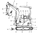
- FIG. 1 is a side view showing the entire structure of an electric excavator to which the present invention is applied.
- an electric excavator includes a lower traveling body 2 having left and right crawlers (crawlers) 1, an upper revolving body 3 that is pivotably mounted on the lower traveling body 2, and the upper revolving body.
- a swing frame 4 that forms the basic lower structure of the body 3, a swing post 5 that is pivotably attached to the front portion of the swing frame 4, and a swing post 5 that can be pivoted vertically
- the lower traveling body 2 drives a substantially H-shaped track frame 10, left and right drive wheels 11 rotatably supported in the vicinity of the left and right rear ends of the track frame 10, and the left and right drive wheels 11, respectively.
- Left and right traveling hydraulic motors 12, and left and right driven wheels (idlers) 13 that are rotatably supported in the vicinity of the left and right front ends of the track frame 10 and are rotated by the driving force of the driving wheels 11 through the crawler belt 1, respectively. It has.
- a blade 14 for earth removal is provided on the front side of the track frame 10 so as to be movable up and down, and the blade 14 is moved up and down by a hydraulic cylinder for blade (not shown).
- a turning wheel (not shown) is provided between the center portion of the track frame 10 and the turning frame 4, and the turning frame 4 with respect to the lower traveling body 2 is disposed radially inside the turning wheel. Is provided with a turning hydraulic motor (not shown).
- the swing post 5 can be rotated in the horizontal direction with respect to the revolving frame 4 via a vertical pin (not shown).
- the swing post 5 is rotated in the horizontal direction by a swing hydraulic cylinder (not shown), whereby the front work machine 6 swings to the left and right.
- the front work machine 6 includes a boom 15 that is rotatably connected to the swing post 5, an arm 16 that is rotatably connected to the distal end of the boom 15, and a pivot that is rotatable to the distal end of the arm 16. And a coupled bucket 17.
- the boom 15, the arm 16, and the bucket 17 are operated by a boom hydraulic cylinder 18, an arm hydraulic cylinder 19, and a bucket hydraulic cylinder 20.
- the bucket 17 can be replaced with, for example, an attachment (not shown) in which an optional hydraulic actuator is incorporated.
- the driver's cab 7 includes a driver seat (seat) 21 on which a driver is seated, a left console box 22 provided on the left side of the driver seat 21, and a right console box provided on the right side of the driver seat 21 (see FIG. Not shown).
- a driver seat (seat) 21 on which a driver is seated
- a left console box 22 provided on the left side of the driver seat 21, and a right console box provided on the right side of the driver seat 21 (see FIG. Not shown).
- an operating device (not shown) having left and right traveling operation levers 23 for operating the left and right traveling hydraulic motors 12 to operate the hydraulic excavator by operating in the front-rear direction. )
- An operation device (not shown) having an option operation pedal (not shown) for instructing the operation of the option hydraulic actuator is provided on the left foot portion of the left travel operation lever 23. .
- the swing post 5 On the right foot portion of the right driving operation lever 23, the swing post 5 (in other words, the entire front work machine 6) is swung left and right by operating the swing hydraulic cylinder by operating in the left and right direction.
- An operating device (not shown) having a swing operating pedal (not shown) is provided.
- the operation of the arm hydraulic cylinder 19 is instructed by operating in the front-rear direction to drive the arm 16, and the operation of the turning hydraulic motor is operated by operating in the left-right direction.
- An operating device (not shown) having a cross operation arm and a turning operation lever 24 for instructing and turning the upper turning body 3 is provided.
- an unlock position (specifically, a lowered position that prevents the driver from getting on and off)
- a lock position (specifically, as shown in FIG. 1).
- a lock lever 25 that is rotated to a position where the driver can get on and off is provided.
- the operation of the boom hydraulic cylinder 18 is instructed by operating in the front-rear direction to drive the boom 15, and the operation of the bucket hydraulic cylinder 20 is operated by operating in the left-right direction.
- An operating device 27 (see FIG. 2 to be described later) having a cross operation type boom / bucket operating lever 26 (see FIG. 2 to be described later) for instructing to drive the bucket 17 and a hydraulic pressure for the blade by operating in the front-rear direction.
- An operation device (not shown) having a blade operation lever (not shown) for instructing the operation of the cylinder to drive the blade 14 is provided.
- the right console box is provided with a key switch 28 (see FIG. 3 described later).
- the key switch 28 includes a key cylinder and a key that can be inserted into the key cylinder, and can be rotated in the order of the OFF position, the ON position, and the START position.
- a rotation speed instruction device 29 (see FIG. 3 described later) having a rotation speed instruction lever (not shown) operable in the front-rear direction is provided.
- the rotation speed instruction device 29 includes a displacement detector (not shown) for detecting the operation position of the rotation speed instruction lever, and a target rotation speed (for example, 1000 to 1000) corresponding to the operation position of the rotation speed instruction lever is detected from the displacement detector. 2400 rpm) instruction signal is output.
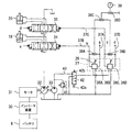
- FIG. 2 is a hydraulic circuit diagram illustrating an example of a configuration of a main part related to the boom 15 and the bucket 17 in the hydraulic drive device.
- the hydraulic drive device includes an inverter device 30 that converts DC power from a battery 8 (for example, a lithium battery) into AC power and outputs the AC power, and a main electric motor that is driven by the AC power from the inverter device 30. 31, a main pump 32 and a pilot pump 33 driven by the main electric motor 31, and a boom direction switch for controlling the flow of pressure oil from the main pump 32 to the boom hydraulic cylinder 18 and the bucket hydraulic cylinder 20, respectively.
- a valve 34, a bucket direction switching valve 35, and a hydraulic pilot type operating device 27 having a boom / bucket operating lever 26 are provided.
- the operating device 27 includes an operating lever 26, a pilot valve 36 ⁇ / b> A that generates a pilot pressure a by reducing the discharge pressure of the pilot pump 33 according to the operation amount on the front side from the neutral position of the operating lever 26,
- the pilot valve 36B that generates the pilot pressure b by reducing the discharge pressure of the pilot pump 33 according to the operation amount on the rear side from the neutral position, and the pilot pump 33 according to the operation amount on the left side from the neutral position of the operation lever 26
- a pilot valve 36C that generates a pilot pressure c by reducing the discharge pressure
- a pilot valve 36D that generates a pilot pressure d by reducing the discharge pressure of the pilot pump 33 according to the operation amount on the right side from the neutral position of the operation lever 26. And have.
- the boom hydraulic cylinder 18 is shortened.
- the pilot pressure b generated by the pilot valve 36B according to the operation amount is output to the pressure receiving portion of the boom direction switching valve 34 via the pilot line 37B, thereby The boom direction switching valve 34 is switched to the switching position on the right side in the figure. As a result, the boom hydraulic cylinder 18 extends.
- the bucket hydraulic cylinder 20 extends.
- the pilot operating pressure generated by the pilot valve 36D according to the operation amount is output to the pressure receiving portion of the bucket direction switching valve 35 via the pilot line 37D, thereby The direction switching valve 35 is switched to the switching position on the left side in the figure.
- the bucket hydraulic cylinder 20 is shortened.
- the configuration of the hydraulic drive device related to the driven members other than the boom 15 and the bucket 17 (specifically, the left and right crawler belts 1, the upper swing body 3, the swing post 5, the blade 14, and the arm 16) is the same.
- These operating devices are hydraulic pilot type like the operating device 27 described above, and the pilot pressure is reduced by reducing the discharge pressure of the pilot pump 33 according to the operating amount of the operating lever (or operating pedal). It has a pilot valve to generate.
- a shuttle valve 38A is connected between the pilot lines 37A and 37B of the operating device 27, a shuttle valve 38B is connected between the pilot lines 37C and 37D of the operating device 27, and the output port of the shuttle valve 38A and the shuttle valve 38B.
- a shuttle valve 38C is connected between these output ports.
- the shuttle valve 38C outputs the highest pressure among the pilot pressures a to d of the operating device 27.
- a shuttle valve group (not shown) is provided to output the highest pressure among the pilot pressures of the operating devices other than the operating device 27, and the shuttle valve (not shown) at the final stage in the shuttle valve group is provided.
- an output port of the shuttle valve 38C are connected to a shuttle valve 38D.
- the shuttle valve 38D outputs the highest pressure (hereinafter referred to as the highest pilot pressure) among the pilot pressures of all the operation devices.
- a pressure sensor 39 is connected to the output port of the shuttle valve 38D, and the pressure sensor 39 detects the maximum pilot pressure.
- a pilot relief valve 41 is connected to the discharge oil passage 40 of the pilot pump 33, and the pilot relief valve 41 defines the maximum discharge pressure of the pilot pump 33.
- a lock valve 42 is provided in the discharge oil passage 40 of the pilot pump (in other words, the oil passage between the pilot pump 33 and the operating device), and this lock valve 42 is used to operate the lock lever 25 described above. It can be switched according to. That is, there is provided a lock switch 43 (see FIG. 3 described later) that opens when the lock lever 25 is at the unlock position (lower position) and closes when the lock lever 25 is at the lock position (up position).
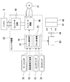
- FIG. 3 is a block diagram showing the configuration of the inverter device 30 together with related devices.
- an inverter device 30 generates AC power from a converter circuit 44 that boosts a DC voltage of about 150 to 180 V from the battery 8 to about 270 V, and DC power boosted by the converter circuit 44.
- An inverter circuit 45 that supplies the electric motor (permanent magnet synchronous motor) 31 and an arithmetic control unit (microcomputer) 46 are provided.
- a cooling water system for cooling the inverter device 30 and the main electric motor 31 is provided.
- the cooling water system includes an air-cooled radiator 47 for cooling the cooling water, and the radiator 47 and the inverter.
- a circulation pump (not shown) for circulating cooling water between the apparatus 30 and the main electric motor 31 is provided.
- An air-cooled oil cooler 48 that cools the hydraulic oil is also provided.
- a cooling fan 49 that generates cooling air to the radiator 47 and the oil cooler 48 and a fan electric motor 50 that is driven by the power of the battery 8 and rotates the cooling fan 49 are provided.
- the arithmetic control unit 46 of the inverter device 30 is configured to receive signals from the key switch 28, the rotation speed instruction device 29, the lock switch 43, and the pressure sensor 39 described above.
- the arithmetic control unit 46 controls the main electric motor 51 via the inverter circuit 45 based on the input signal described above, and the fan control via a motor drive relay (not shown) based on the input signal described above.
- a fan control unit 52 that controls the electric motor 50.
- the control procedure of the arithmetic control unit 46 will be described with reference to FIG.
- FIG. 4 is a flowchart showing the control processing contents of the arithmetic control unit 46 of the inverter device 30.
- step 100 when the driver operates the key switch 28 from the OFF position to the START position with the intention of starting the hydraulic excavator, the power source of the inverter device 30 and the like is turned on, and the key switch 28 is turned on. Is input to the arithmetic control unit 46 of the inverter device 30.
- step 110 the main controller 51 and the fan controller 52 determine whether or not the signal from the lock switch 43 has been input, thereby determining whether or not the lock lever 25 is in the unlocked position. To do. For example, when the lock lever 25 is in the locked position (in other words, when the signal from the lock switch 43 is not input), the determination at step 110 is not satisfied, and the routine proceeds to step 120.
- step 120 the fan control unit 52 stops the fan electric motor 50 and stops the cooling fan 49. Specifically, the relay contact is opened without outputting a control signal to the motor drive relay, and the power supply to the fan electric motor 50 is cut off.
- step 130 the main control unit 51 stops the main drive motor 31 via the inverter circuit 45. Then, it returns to step 110 and repeats the same procedure as the above.
- step 140 the fan control unit 52 drives the fan electric motor 50 to rotate the cooling fan 49. Specifically, a control signal is output to the motor drive relay to excite the relay coil to close the contact, and power is supplied to the fan electric motor 50.
- step 150 the main control unit 51 determines that all the operation devices are not operated based on the maximum pilot pressure detected by the pressure sensor 39 (in other words, the operation levers or operation pedals of all the operation devices are neutral). Whether or not a predetermined time ⁇ t1 (for example, 4 seconds) has passed in a state where the lock lever 25 is operated to the unlocking position and all the operation devices are not operated. Determine whether. More specifically, the main control unit 51 first determines whether or not the maximum pilot pressure detected by the pressure sensor 39 is less than a preset first threshold value P1 (see FIG. 5 described later). It is determined whether the operating device is not operated.
- a predetermined time ⁇ t1 for example, 4 seconds
- the timer is activated to determine whether or not the time is equal to or longer than the predetermined time ⁇ t1. . After the timer is activated, it is determined by determining whether or not the maximum pilot pressure detected by the pressure sensor 39 is equal to or higher than a preset second threshold value P2 (where P2> P1, see FIG. 5 described later). It is determined whether the operating device is operated. If it is determined which of the operating devices is being operated, the timer is reset.
- step 150 when any one of the operation devices is operated in step 150, or when the predetermined time ⁇ t1 has not elapsed in a state where the lock lever 25 is operated to the unlock position and all the operation devices are not operated.
- the determination at step 150 is not satisfied, and the routine goes to step 160.
- step 160 the main control unit 51 controls the voltage applied to the main drive motor 31 via the inverter circuit 45 so that the rotation number of the main drive motor 31 becomes the target rotation number instructed by the rotation number instruction device 28. . Then, it returns to step 110 and repeats the same procedure as the above.
- step 150 the main control unit 51 stops the main drive motor 31 via the inverter circuit 45. Then, it returns to step 110 and repeats the same procedure as the above.
- FIG. 5 is a time chart for explaining the operation of the present embodiment.
- the inverter control device 30 satisfies the determination at step 110 in FIG. 4, and drives the fan electric motor 50 at step 140. Further, during the initial start of the hydraulic excavator or while the driver is operating any of the operation devices (time t1 to t2), the determination in step 150 is not satisfied, and the main electric motor 31 is driven in step 160.
- step 150 the determination in step 150 is not satisfied, and the driving of the main electric motor 50 is continued in step 160.
- the predetermined time ⁇ t1 has elapsed (time t3)
- the determination in step 150 is satisfied, and in step 130, the main electric motor 31 is stopped.
- the driver operates any one of the operation devices (time t4)
- the determination in step 150 is not satisfied, and the main electric motor 31 is driven in step 160.
- the inverter device 30 drives and stops a circulation pump that circulates the cooling water of the radiator 47 in conjunction with driving and stopping of the fan drive motor 50. You may control as follows. In such a modification, the consumption of battery power can be further suppressed.
- the fan control means when the lock lever 25 is operated to the unlock position, a signal from the lock switch 43 is input, and a control signal is output to the motor drive relay accordingly.
- the inverter device 30 having a fan control function for driving the fan electric motor 50 has been described as an example, but is not limited thereto. That is, for example, the fan control function may be separated from the inverter device 30 to be another control device. Further, for example, the lock switch 43 and the motor drive relay may be connected by wiring so that a signal from the lock switch 43 is directly output to the motor drive relay. Even in such a modification, the same effect as described above can be obtained.
- the lock means is a lock switch 43 that opens and closes in response to the operation of the lock lever 25, and an electromagnetic type that is provided in the discharge oil passage 40 of the pilot pump 33 and operates according to a signal from the lock switch 43.
- the present invention is not limited to this. That is, for example, a manual lock valve mechanically connected to the lock lever 25 may be provided. Further, for example, a lever engaging member that is mechanically connected to the lock lever 25 and restricts the operation lever (or operation pedal) of the operation device when the lock lever is operated to the lock position may be provided. Even in such a modification, the same effect as described above can be obtained.
- the fan electric motor 50 that rotates the cooling fan 49 is described as an example of the fan electric device.
- the present invention is not limited to this. That is, for example, a fan hydraulic motor that rotates the cooling fan 49, a fan pump that generates pressure oil to be supplied to the fan hydraulic motor, and a fan electric motor that drives the fan pump may be provided. Good. Even in such a modification, the same effect as described above can be obtained.
- the temperature sensor that detects the temperature of the cooling water that is the cooling target of the radiator 47 and the temperature that detects the temperature of the hydraulic oil that is the cooling target of the oil cooler 48. Sensors may be provided, and detection signals from these temperature sensors may be output to the arithmetic control unit of the inverter device 30.
- the fan control unit 51 of the arithmetic control unit 46 of the inverter device 30 is configured so that, for example, the lock lever 25 is in the unlocked position, the detected temperature of the hydraulic oil is less than a predetermined set value, and the cooling water The fan electric motor 50 may be stopped when the detected temperature is lower than a predetermined set value.
- the detected temperature of the hydraulic oil becomes equal to or higher than a predetermined set value, or the cooling water If the detected temperature is not equal to or higher than a predetermined set value, the fan electric motor 50 may not be started. Even in such a modification, the same effect as described above can be obtained.
- all the operation devices are hydraulic pilot type, and a pressure sensor 39 for detecting the highest pressure (maximum pilot pressure) among the pilot pressures of these operation devices is provided.
- a pressure sensor 39 for detecting the highest pressure (maximum pilot pressure) among the pilot pressures of these operation devices.
- the present invention is not limited to this. That is, for example, when an electric lever type operation device (specifically, a device having a displacement detector that outputs an electric operation signal corresponding to the operation direction and operation amount of the operation lever) is used, the electric operation from the operation device It may be determined based on the signal. In such a case, the same effect as described above can be obtained.
- FIG. 6 is a flowchart showing the control processing contents of the arithmetic control unit of the inverter device 30 in the present embodiment.
- step 200 when the driver operates the key switch 28 from the OFF position to the START position with the intention of starting the hydraulic excavator, the power source of the inverter device 30 and the like is turned on, and the key switch 28 is turned on. Is input to the arithmetic control unit 46 of the inverter device 30.
- step 210 the main control unit 51 and the fan control unit 52 determine whether or not the signal from the lock switch 43 is input, thereby determining whether or not the lock lever 25 is in the unlocked position. To do. For example, when the lock lever 25 is at the lock position (in other words, when the signal from the lock switch 43 is not input), the determination at step 210 is not satisfied, and the routine proceeds to step 220.
- step 220 the fan control unit 52 stops the fan electric motor 50 and stops the cooling fan 49.
- step 230 the main control unit 51 stops the main drive motor 31 via the inverter circuit 45. Then, it returns to step 210 and repeats the same procedure as the above.
- Step 240 the main control unit 51 determines whether all the operation devices are not operated based on the maximum pilot pressure detected by the pressure sensor 39, and the lock lever 25 is operated to the unlocking position and all the operation devices are operated. It is determined whether or not a predetermined time ⁇ t1 (for example, 4 seconds) that has been set in advance has passed without the operating device being operated.
- ⁇ t1 for example, 4 seconds
- step 250 the fan control unit 52 drives the fan electric motor 50 to rotate the cooling fan 49. Then, the process proceeds to step 260 where the main control unit 51 applies the voltage applied to the main drive motor 31 via the inverter circuit 45 so that the rotation number of the main drive motor 31 becomes the target rotation number specified by the rotation number instruction device 28. To control. Then, it returns to step 210 and repeats the same procedure as the above.
- step 240 the fan control unit 52 stops the fan electric motor 50 and stops the cooling fan 49.
- step 230 the main control unit 51 stops the main drive motor 31 via the inverter circuit 45. Then, it returns to step 210 and repeats the same procedure as the above.
- the electric hydraulic excavator provided with the main electric motor 31 as a prime mover for driving the main pump 32 and the like has been described as an application target of the present invention.
- the present invention is not limited thereto. That is, for example, the present invention may be applied to an engine-type hydraulic excavator provided with an engine as a prime mover.
- the present invention may be applied to a hybrid hydraulic excavator provided with an engine and a main electric motor as a prime mover.
- Inverter device (fan control means, main control means) 31 Main electric motor 32 Main pump 39 Pressure sensor (operation detection means) 42 Lock valve (locking means) 47 Radiator (Heat exchanger) 48 Oil cooler (heat exchanger) 49 Cooling fan 50 Electric motor for fan (fan electric device)
Landscapes
- Engineering & Computer Science (AREA)
- Structural Engineering (AREA)
- Mining & Mineral Resources (AREA)
- Civil Engineering (AREA)
- General Engineering & Computer Science (AREA)
- Chemical & Material Sciences (AREA)
- Combustion & Propulsion (AREA)
- Transportation (AREA)
- Mechanical Engineering (AREA)
- Power Engineering (AREA)
- Operation Control Of Excavators (AREA)
- Component Parts Of Construction Machinery (AREA)
- Cooling, Air Intake And Gas Exhaust, And Fuel Tank Arrangements In Propulsion Units (AREA)
Abstract
Description
25 ロックレバー
27 操作装置
30 インバータ装置(ファン制御手段、メイン制御手段)
31 メイン電動モータ
32 メインポンプ
39 圧力センサ(操作検出手段)
42 ロック弁(ロック手段)
47 ラジエータ(熱交換器)
48 オイルクーラ(熱交換器)
49 冷却ファン
50 ファン用電動モータ(ファン電動装置)
Claims (4)
- 空冷式の熱交換器(47,48)と、前記熱交換器(47,48)への冷却風を生成する冷却ファン(49)と、バッテリ(8)と、前記バッテリ(8)の電力によって駆動され前記冷却ファン(49)を回転するファン電動装置(50)と、前記ファン電動装置(50)を駆動制御するファン制御手段(30)と、乗降口に設けられロック解除位置とロック位置に操作されるロックレバー(25)と、油圧アクチュエータの動作を指示する操作装置(27等)と、前記ロックレバー(25)がロック位置に操作された場合に前記操作装置(27等)の操作を無効又は不能とするロック手段(42)とを備えた建設機械において、
前記ファン制御手段(30)は、前記ロックレバー(25)がロック位置に操作された場合に、前記ファン電動装置(50)を停止させることを特徴とする建設機械。 - 請求項1記載の建設機械において、前記操作装置(27等)が操作されていない状態であるか否かを検出する操作検出手段(39)を備え、
前記ファン制御手段(30)は、前記ロックレバー(25)がロック解除位置に操作され且つ前記操作装置(27等)が操作されていない状態で予め設定された所定時間が経過した場合に、前記ファン電動装置(50)を停止させることを特徴とする建設機械。 - 請求項1又は2記載の建設機械において、前記油圧アクチュエータに供給する圧油を生成するメインポンプ(32)と、前記バッテリ(8)の電力によって駆動され前記メインポンプを駆動するメイン電動モータ(31)と、前記メイン電動モータを駆動制御するメイン制御手段(30)とを備え、
前記メイン制御手段(30)は、前記ロックレバー(25)がロック位置に操作された場合に、前記メイン電動モータ(31)を停止させることを特徴とする建設機械。 - 請求項3記載の建設機械において、
前記メイン制御手段(30)は、前記ロックレバー(25)がロック解除位置に操作され且つ前記操作装置(27等)が操作されていない状態で予め設定された所定時間が経過した場合に、前記メイン電動モータ(31)を停止させることを特徴とする建設機械。
Priority Applications (5)
| Application Number | Priority Date | Filing Date | Title |
|---|---|---|---|
| US13/503,942 US8672072B2 (en) | 2010-06-09 | 2011-05-20 | Construction machine |
| IN3230DEN2012 IN2012DN03230A (ja) | 2010-06-09 | 2011-05-20 | |
| EP11792267.4A EP2581501B1 (en) | 2010-06-09 | 2011-05-20 | Construction machine |
| KR1020127014544A KR20130090744A (ko) | 2010-06-09 | 2011-05-20 | 건설 기계 |
| CN201180004815.1A CN102639791B (zh) | 2010-06-09 | 2011-05-20 | 工程机械 |
Applications Claiming Priority (2)
| Application Number | Priority Date | Filing Date | Title |
|---|---|---|---|
| JP2010-132204 | 2010-06-09 | ||
| JP2010132204A JP5171888B2 (ja) | 2010-06-09 | 2010-06-09 | 建設機械 |
Publications (1)
| Publication Number | Publication Date |
|---|---|
| WO2011155309A1 true WO2011155309A1 (ja) | 2011-12-15 |
Family
ID=45097918
Family Applications (1)
| Application Number | Title | Priority Date | Filing Date |
|---|---|---|---|
| PCT/JP2011/061688 Ceased WO2011155309A1 (ja) | 2010-06-09 | 2011-05-20 | 建設機械 |
Country Status (7)
| Country | Link |
|---|---|
| US (1) | US8672072B2 (ja) |
| EP (1) | EP2581501B1 (ja) |
| JP (1) | JP5171888B2 (ja) |
| KR (1) | KR20130090744A (ja) |
| CN (1) | CN102639791B (ja) |
| IN (1) | IN2012DN03230A (ja) |
| WO (1) | WO2011155309A1 (ja) |
Cited By (1)
| Publication number | Priority date | Publication date | Assignee | Title |
|---|---|---|---|---|
| WO2020059130A1 (ja) * | 2018-09-21 | 2020-03-26 | 日立建機株式会社 | 油圧駆動ファン制御装置 |
Families Citing this family (18)
| Publication number | Priority date | Publication date | Assignee | Title |
|---|---|---|---|---|
| JP5356427B2 (ja) * | 2011-02-03 | 2013-12-04 | 日立建機株式会社 | ハイブリッド式建設機械 |
| US9484602B1 (en) | 2013-08-22 | 2016-11-01 | OSC Manufacturing & Equipment Services, Inc. | Light tower having a battery housing |
| US9567893B2 (en) * | 2013-12-23 | 2017-02-14 | Modine Manufacturing Company | System and method for controlling an engine cooling fan |
| US10749224B2 (en) | 2015-08-17 | 2020-08-18 | OSC Manufacturing & Equipment Services, Inc. | Rechargeable battery power system having a battery with multiple uses |
| JP6577539B2 (ja) * | 2017-08-23 | 2019-09-18 | キャタピラー エス エー アール エル | 建設機械の操作装置 |
| JP2019190107A (ja) * | 2018-04-24 | 2019-10-31 | ヤンマー株式会社 | 電動式作業機械 |
| JP7246209B2 (ja) * | 2019-03-04 | 2023-03-27 | 株式会社小松製作所 | 作業車両の制御装置、及び作業車両 |
| JP7215264B2 (ja) * | 2019-03-19 | 2023-01-31 | コベルコ建機株式会社 | 建設機械 |
| DE112020003859T5 (de) | 2019-09-17 | 2022-04-28 | Komatsu Ltd. | Arbeitsfahrzeug, hebeleinheit und verfahren zur automatischen steuerung eines aktuators |
| JP7177967B2 (ja) * | 2020-03-30 | 2022-11-24 | 日立建機株式会社 | 建設機械 |
| JP7422610B2 (ja) * | 2020-06-02 | 2024-01-26 | ヤンマーホールディングス株式会社 | 電動式建設機械 |
| IT202000013378A1 (it) * | 2020-06-05 | 2021-12-05 | Prinoth Spa | Veicolo cingolato, metodo di controllo e programma per elaboratore elettronico di detto veicolo |
| US11334662B2 (en) * | 2020-07-14 | 2022-05-17 | Bank Of America Corporation | Tamper-evident travel devices equipped with secure re-image file (s) |
| US11707980B2 (en) * | 2020-12-16 | 2023-07-25 | Cnh Industrial America Llc | Track assembly with electric motor |
| JP7848464B2 (ja) * | 2021-11-10 | 2026-04-21 | コベルコ建機株式会社 | 作業機械 |
| CN118871671A (zh) | 2022-03-25 | 2024-10-29 | 摩丁制造公司 | 带有组合电触点的泵 |
| US12404945B2 (en) | 2022-03-25 | 2025-09-02 | Modine Manufacturing Company | Valve with configurable default position |
| EP4506510A4 (en) * | 2022-04-01 | 2026-03-25 | Kubota Kk | CONSTRUCTION EQUIPMENT |
Citations (5)
| Publication number | Priority date | Publication date | Assignee | Title |
|---|---|---|---|---|
| JP2002275936A (ja) | 2001-03-12 | 2002-09-25 | Hitachi Constr Mach Co Ltd | 旋回式建設機械 |
| JP2004224133A (ja) * | 2003-01-21 | 2004-08-12 | Kobelco Contstruction Machinery Ltd | 建設機械の動力制御装置 |
| JP2006057348A (ja) * | 2004-08-20 | 2006-03-02 | Sumitomo (Shi) Construction Machinery Manufacturing Co Ltd | 建設機械の冷却装置 |
| JP2007126898A (ja) | 2005-11-04 | 2007-05-24 | Hitachi Constr Mach Co Ltd | 建設機械 |
| JP2009197514A (ja) | 2008-02-22 | 2009-09-03 | Hitachi Constr Mach Co Ltd | 電気駆動式作業機械 |
Family Cites Families (13)
| Publication number | Priority date | Publication date | Assignee | Title |
|---|---|---|---|---|
| US4366881A (en) * | 1980-12-11 | 1983-01-04 | J. I. Case Company | Flip-up control console |
| DE4019478A1 (de) * | 1989-06-20 | 1991-01-10 | Honda Motor Co Ltd | Elektrische spannungsversorgungs-kontrolleinheit fuer ein kraftfahrzeug |
| US5425431A (en) * | 1994-02-18 | 1995-06-20 | Clark Equipment Company | Interlock control system for power machine |
| KR0165960B1 (ko) * | 1996-09-16 | 1999-10-01 | 대우중공업주식회사 | 로더용 페달록킹장치 |
| CN1093609C (zh) * | 1997-09-19 | 2002-10-30 | 日立建机株式会社 | 建筑机械的冷却装置及建筑机械 |
| KR100306009B1 (ko) * | 1999-07-15 | 2001-09-13 | 조영석 | 고장감지기능을 가진 자동차용 냉각팬 구동장치 |
| US6363906B1 (en) * | 2000-03-06 | 2002-04-02 | Detroit Diesel Corporation | Idle shutdown override with defeat protection |
| US7740259B2 (en) * | 2006-02-03 | 2010-06-22 | Crown Equipment Corporation | Movable step for a materials handling vehicle |
| WO2008055216A2 (en) * | 2006-10-31 | 2008-05-08 | Enviro-Cool, Inc. | Air management system for truck |
| US8020655B2 (en) * | 2007-09-04 | 2011-09-20 | Honda Motor Co., Ltd. | Variable pitch radiator fan control system |
| CN201190297Y (zh) * | 2008-04-30 | 2009-02-04 | 常林股份有限公司 | 一种铲运机械的冷却装置 |
| JP5185082B2 (ja) * | 2008-11-18 | 2013-04-17 | 日立建機株式会社 | 電動式油圧作業機械 |
| CN201473992U (zh) * | 2009-07-20 | 2010-05-19 | 沃得重工(中国)有限公司(中外合资) | 一种液压挖掘机散热器 |
-
2010
- 2010-06-09 JP JP2010132204A patent/JP5171888B2/ja active Active
-
2011
- 2011-05-20 EP EP11792267.4A patent/EP2581501B1/en active Active
- 2011-05-20 US US13/503,942 patent/US8672072B2/en active Active
- 2011-05-20 WO PCT/JP2011/061688 patent/WO2011155309A1/ja not_active Ceased
- 2011-05-20 KR KR1020127014544A patent/KR20130090744A/ko not_active Abandoned
- 2011-05-20 IN IN3230DEN2012 patent/IN2012DN03230A/en unknown
- 2011-05-20 CN CN201180004815.1A patent/CN102639791B/zh active Active
Patent Citations (5)
| Publication number | Priority date | Publication date | Assignee | Title |
|---|---|---|---|---|
| JP2002275936A (ja) | 2001-03-12 | 2002-09-25 | Hitachi Constr Mach Co Ltd | 旋回式建設機械 |
| JP2004224133A (ja) * | 2003-01-21 | 2004-08-12 | Kobelco Contstruction Machinery Ltd | 建設機械の動力制御装置 |
| JP2006057348A (ja) * | 2004-08-20 | 2006-03-02 | Sumitomo (Shi) Construction Machinery Manufacturing Co Ltd | 建設機械の冷却装置 |
| JP2007126898A (ja) | 2005-11-04 | 2007-05-24 | Hitachi Constr Mach Co Ltd | 建設機械 |
| JP2009197514A (ja) | 2008-02-22 | 2009-09-03 | Hitachi Constr Mach Co Ltd | 電気駆動式作業機械 |
Cited By (3)
| Publication number | Priority date | Publication date | Assignee | Title |
|---|---|---|---|---|
| WO2020059130A1 (ja) * | 2018-09-21 | 2020-03-26 | 日立建機株式会社 | 油圧駆動ファン制御装置 |
| JPWO2020059130A1 (ja) * | 2018-09-21 | 2020-12-17 | 日立建機株式会社 | 油圧駆動ファン制御装置 |
| US11396839B2 (en) | 2018-09-21 | 2022-07-26 | Hitachi Construction Machinery Co., Ltd. | Hydraulic drive fan control device |
Also Published As
| Publication number | Publication date |
|---|---|
| IN2012DN03230A (ja) | 2015-10-23 |
| CN102639791B (zh) | 2014-11-12 |
| US20120205171A1 (en) | 2012-08-16 |
| EP2581501A1 (en) | 2013-04-17 |
| EP2581501B1 (en) | 2019-03-13 |
| CN102639791A (zh) | 2012-08-15 |
| JP2011256608A (ja) | 2011-12-22 |
| US8672072B2 (en) | 2014-03-18 |
| EP2581501A4 (en) | 2017-09-20 |
| JP5171888B2 (ja) | 2013-03-27 |
| KR20130090744A (ko) | 2013-08-14 |
Similar Documents
| Publication | Publication Date | Title |
|---|---|---|
| JP5171888B2 (ja) | 建設機械 | |
| JP5389100B2 (ja) | 建設機械の電動駆動装置 | |
| JP5737598B2 (ja) | 電動式建設機械 | |
| KR101877073B1 (ko) | 하이브리드식 건설 기계 | |
| JP2010121328A (ja) | 電動式油圧作業機械 | |
| JP5165250B2 (ja) | 建設機械の冷却装置 | |
| JP5699155B2 (ja) | 旋回駆動制御装置 | |
| JP2011078277A (ja) | 電動式建設機械 | |
| JP7267775B2 (ja) | 作業車両 | |
| JP5986042B2 (ja) | 建設機械の走行警報装置 | |
| WO2021049418A1 (ja) | 建設機械 | |
| JP4675850B2 (ja) | 作業機械 | |
| CN114207224A (zh) | 工程机械 | |
| JP2011117316A (ja) | 建設機械の制御装置 | |
| KR20130129262A (ko) | 쇼벨 | |
| JP5572528B2 (ja) | 電動式建設機械の制御機構および制御方法 | |
| JP4666933B2 (ja) | 回転式作業機の油圧制御回路 | |
| JP4312681B2 (ja) | 建設機械の冷却装置 | |
| JP7436301B2 (ja) | 建設機械 | |
| JP2004269067A (ja) | 建設機械の操作レバーロック作動装置 | |
| JP2006097427A (ja) | 建設機械の旋回制御装置 | |
| JP2013217070A (ja) | 建設機械の制御装置 | |
| JP2012162940A (ja) | 建設機械の制御装置 | |
| JP2005307791A (ja) | 作業車用誤操作防止装置 | |
| JP2005307492A (ja) | 作業車用誤操作防止装置 |
Legal Events
| Date | Code | Title | Description |
|---|---|---|---|
| WWE | Wipo information: entry into national phase |
Ref document number: 201180004815.1 Country of ref document: CN |
|
| 121 | Ep: the epo has been informed by wipo that ep was designated in this application |
Ref document number: 11792267 Country of ref document: EP Kind code of ref document: A1 |
|
| WWE | Wipo information: entry into national phase |
Ref document number: 3230/DELNP/2012 Country of ref document: IN |
|
| WWE | Wipo information: entry into national phase |
Ref document number: 13503942 Country of ref document: US |
|
| WWE | Wipo information: entry into national phase |
Ref document number: 2011792267 Country of ref document: EP |
|
| ENP | Entry into the national phase |
Ref document number: 20127014544 Country of ref document: KR Kind code of ref document: A |
|
| NENP | Non-entry into the national phase |
Ref country code: DE |