WO2011155321A1 - 車体前部構造 - Google Patents
車体前部構造 Download PDFInfo
- Publication number
- WO2011155321A1 WO2011155321A1 PCT/JP2011/061837 JP2011061837W WO2011155321A1 WO 2011155321 A1 WO2011155321 A1 WO 2011155321A1 JP 2011061837 W JP2011061837 W JP 2011061837W WO 2011155321 A1 WO2011155321 A1 WO 2011155321A1
- Authority
- WO
- WIPO (PCT)
- Prior art keywords
- plate
- vehicle body
- cross member
- lower panel
- joined
- Prior art date
- Legal status (The legal status is an assumption and is not a legal conclusion. Google has not performed a legal analysis and makes no representation as to the accuracy of the status listed.)
- Ceased
Links
Images






Classifications
-
- B—PERFORMING OPERATIONS; TRANSPORTING
- B62—LAND VEHICLES FOR TRAVELLING OTHERWISE THAN ON RAILS
- B62D—MOTOR VEHICLES; TRAILERS
- B62D25/00—Superstructure or monocoque structure sub-units; Parts or details thereof not otherwise provided for
- B62D25/08—Front or rear portions
-
- B—PERFORMING OPERATIONS; TRANSPORTING
- B62—LAND VEHICLES FOR TRAVELLING OTHERWISE THAN ON RAILS
- B62D—MOTOR VEHICLES; TRAILERS
- B62D25/00—Superstructure or monocoque structure sub-units; Parts or details thereof not otherwise provided for
- B62D25/08—Front or rear portions
- B62D25/14—Dashboards as superstructure sub-units
-
- B—PERFORMING OPERATIONS; TRANSPORTING
- B62—LAND VEHICLES FOR TRAVELLING OTHERWISE THAN ON RAILS
- B62D—MOTOR VEHICLES; TRAILERS
- B62D25/00—Superstructure or monocoque structure sub-units; Parts or details thereof not otherwise provided for
- B62D25/20—Floors or bottom sub-units
- B62D25/2009—Floors or bottom sub-units in connection with other superstructure subunits
- B62D25/2045—Floors or bottom sub-units in connection with other superstructure subunits the subunits being fire walls
Definitions
- the present invention includes left and right front side frames that are positioned on both left and right sides of a front portion of a vehicle body and extending in the front-rear direction of the vehicle body, and are positioned behind the left and right front side frames so that the vehicle body is front and rear
- the present invention relates to a vehicle body front structure including a dashboard lower panel to be partitioned.
- the dashboard lower panel is composed of a vertical plate-shaped partition plate formed so as to partition the vehicle body into the front and the rear, and an inclined plate inclined downward from the lower end of the partition plate.
- the dashboard lower panel is reinforced by a cross member extending in the vehicle width direction.
- Patent Document 1 and Patent Document 2 A technique in which a dashboard lower panel is reinforced by a cross member is known from Patent Document 1 and Patent Document 2.
- the dashboard lower panel known from Patent Document 1 is composed of two members, an upper half upper panel and a lower half lower panel.
- the upper panel is a vertical plate-like member, and a bent portion elongated in the vehicle width direction is integrally formed at the lower end.
- the bent portion is formed in a V-shaped cross section that opens rearward of the vehicle body.
- the lower panel is composed of a vertical plate-shaped portion joined to the bent portion so as to close the opening of the V-shaped cross section, and an inclined plate-shaped portion inclined downward from the lower end of the vertical plate-shaped portion.
- a closed cross-sectional body elongated in the vehicle width direction is constituted by the bent portion of the V-shaped cross section of the upper panel and the vertical plate-shaped portion of the lower panel.
- the dashboard lower panel is reinforced by the closed cross section. Since the lower panel is a separate member with respect to the upper panel, the number of parts of the vehicle body increases, which may cause an increase in cost.
- the dashboard lower panel known from Patent Document 2 is an integrally molded product composed of an upper half vertical plate and a lower half inclined plate.
- the inclined plate is inclined rearward and downward from the lower end of the upper half vertical plate.
- the vertical plate is reinforced by a cross member extending in the vehicle width direction.
- the cross member is positioned above the bent portion between the vertical plate and the inclined plate. Since the cross member is a separate member with respect to the dashboard lower panel, the number of parts of the vehicle body increases, which may increase the cost.
- An object of the present invention is to provide a technique capable of increasing the rigidity of a dashboard lower panel while reducing the cost of a vehicle body.
- the left and right front side frames that are located on the left and right sides of the front portion of the vehicle body and extend in the front-rear direction of the vehicle body, and the vehicle body that is located behind the left and right front side frames
- a dashboard lower panel that divides the vehicle body into the rear
- the dashboard lower panel includes a vertical plate-shaped partition plate formed to partition the vehicle body into the front and the rear, and the partition An inclined plate inclined downward from the lower end of the plate, and at least a part of the rear surface of the partition plate is reinforced by a reinforcing plate, the reinforcing plate has an extension at the lower end, and the extension The portion extends from above the bent portion of the partition plate and the inclined plate, extends to the rear of the bent portion, and is joined to the inclined plate.
- the vehicle width direction Elongated closed cross section There has been configured, it is characterized.
- an upward convex tunnel portion extending rearward from the lower portion of the dashboard lower panel, and extending in the vehicle width direction along the convex shape of the tunnel portion, the upper portion of the tunnel portion And a cross member provided on the rear surface of the dashboard lower panel and extending in the vehicle width direction, wherein the cross member is joined to the extension.
- the extension portion is a substantially inverted L-shaped member in cross-section, and is rearward from the upper side of the bent portion, generally along at least one of the upper surfaces of the left and right front side frames.
- a horizontal plate extending from the rear end of the horizontal plate and joined to the inclined plate.
- one end of the cross member in the vehicle width direction is formed in a shape matching the cross-sectional shape of one end of the extension portion in the vehicle width direction, and the one ends are joined to each other. It is characterized by that.
- the left and right front side frames are substantially horizontal left and right horizontal portions positioned in front of the partition plate, and left and right left and right inclined portions inclined rearwardly from the rear ends of the left and right horizontal portions.
- the inclined portion of the front side frame which is located in the vicinity of the horizontal plate among the left and right front side frames is formed by a bracket positioned in the vicinity of the horizontal plate. It is joined to the reinforcing plate.
- the bracket is a substantially L-shaped member in cross-sectional view, and is a horizontal plate-like first joining portion joined to at least one of the upper surfaces of the left and right inclined portions, and the first A vertical plate-like second joint that stands up from one joint and is joined to the partition plate and the reinforcing plate, and a rib that protrudes from the first joint to the second joint. It is characterized by that.
- the dashboard lower panel is reinforced by a cross member extending in the vehicle width direction along the bent portion, and at the vehicle width center at the rear end of the inclined plate of the dashboard lower panel, A high-strength plate having a higher strength than the inclined plate is provided, and the inclined plate has a weaker intermediate portion sandwiched between the cross member and the high-strength plate than other portions not sandwiched. It is characterized by.
- the partition plate is reinforced by a panel reinforcing member at a portion to which a brake booster for adjusting the brake operating force by the driver is attached, and the panel reinforcing member is separated from the cross member. It is characterized by that.
- the invention according to claim 9 is characterized in that the high-strength plate is stretched between rear portions of the left and right front side frames.
- the said dashboard lower panel is equipped with the convex front tunnel part extended upwards from the lower part back,
- the said high strength board is comprised with the high-tensile steel plate,
- the said front An upper convex rear tunnel portion, which is located immediately behind the front tunnel portion, is integrally formed, and the rear tunnel portion extends rearward in connection with the rear end of the front tunnel portion. .
- the invention according to claim 11 further includes a front cross member spanned between rear portions of the left and right front side frames, and the front edge of the front cross member has a vehicle width center at both ends in the vehicle width direction. Is formed in a substantially arch shape that is curved as a whole so as to be positioned rearward, and the high-strength plate is joined to the front cross member along the front edge.
- the rear surface of the vertical partition plate is reinforced by the reinforcing plate in the dashboard lower panel.
- the reinforcing plate has an extension at the lower end.
- the extension portion extends from above the bent portion of the partition plate and the inclined plate to the rear of the bent portion and is joined to the inclined plate.
- the extended section and the dashboard lower panel form a closed cross-sectional body that is elongated in the vehicle width direction.
- a closed cross-section body for reinforcing the periphery of the bent portion of the dashboard lower panel is configured by a simple configuration in which the reinforcing plate for increasing the surface rigidity of the partition plate is simply combined with the dashboard lower panel. be able to.
- the rigidity of the dashboard lower panel can be increased, and as a result, the rigidity of the vehicle body can be increased. Therefore, the number of parts of the dashboard lower panel and the members that reinforce the panel can be suppressed as much as possible. For this reason, the rigidity of the dashboard lower panel can be increased while reducing the weight and cost of the vehicle body. Furthermore, the rigidity of the reinforcing plate is increased by the closed cross-sectional body. Since the thickness of the reinforcing plate itself can be reduced, the weight of the vehicle body can be further reduced. In addition, by reducing the thickness of the reinforcing plate, the formability of the reinforcing plate itself is enhanced.
- a cross member is provided on the upper part of the tunnel part and on the rear surface of the dashboard lower panel.
- the cross member extends in the vehicle width direction along the convex shape of the tunnel portion.
- Such a cross member can be constituted by a separate member from the dashboard lower panel and the tunnel portion of the panel. For this reason, even if the cross member has a shape along the convex shape of the tunnel portion, it can be easily formed by a general molding method such as press molding. Therefore, regardless of the relative positional deviation (including height deviation) of the tunnel part with respect to the extension part, the joining position (including height) of the cross member joined to the extension part is optimal. Can be set to be Furthermore, since the cross member is joined to the extension, the length of the cross member can be shortened accordingly.
- the extension for forming the closed cross-section body in combination with the dashboard lower panel is formed in a substantially inverted L shape in cross-sectional view.
- the horizontal plate that forms the upper side of the inverted L-shape extends rearward while being generally along at least one of the upper surfaces of the left and right front side frames. For this reason, when a so-called frontal collision occurs in which a collision force acts on the front surface of the vehicle, the collision force from the front is transmitted from the front end of the front side frame to the rear, and is positioned on the extension of the front side frame. It is transmitted to the horizontal plate. Therefore, the extension portion can efficiently receive the collision force from the front side frame and distribute it around the vehicle body.
- one end of the cross member in the vehicle width direction is formed in a shape that matches the cross-sectional shape of one end of the extension portion in the vehicle width direction. Since each one end is the same cross-sectional shape, it can join smoothly mutually.
- the inclined portion of the front side frame located near the horizontal plate is joined to the partition plate and the reinforcing plate by the bracket located near the horizontal plate.
- the collision force from the front is transmitted from the inclined portion of the front side frame to the partition plate, the reinforcing plate, and the closed cross-section body via the bracket. Therefore, although the rear part of the front side frame is inclined, the extension part can sufficiently receive the collision force from the inclined part.
- the bracket is formed into a highly rigid member by being formed in a substantially L shape in sectional view in which deformation is restricted by the rib. For this reason, the bracket can sufficiently transmit the collision force transmitted from the inclined portion to the partition plate, the reinforcing plate, and the closed cross-section body.
- strength board (for example, board
- a member for example, an engine
- disposed in front of the dashboard lower panel is displaced rearward by a collision force from the front and hits the dashboard lower panel, the fragile portion can be greatly deformed rearward. Accordingly, the amount of displacement of the member disposed in front of the dashboard lower panel can be increased, and as a result, the impact can be further absorbed. And since a weak part deform
- a portion of the partition plate to which the brake booster is attached is reinforced by the panel reinforcing member.
- the panel reinforcing member is separated from a cross member for reinforcing the dashboard lower panel. For this reason, when the cross member is displaced rearward or / and deformed by a collision force from the front, the panel reinforcing member is hardly affected by the cross member, and as a result, the brake booster is also hardly affected.
- the high-strength plate provided at the rear end of the inclined plate of the dashboard lower panel is stretched between the rear portions of the left and right front side frames. For this reason, since the rear end portion of the inclined plate is further strengthened, the deformation performance of the fragile portion due to the collision force can be further enhanced. As a result, it is possible to further suppress the entire dashboard lower panel from being deformed rearward.
- the rear tunnel portion provided on the high-strength plate is connected to the front tunnel portion provided on the dashboard lower panel. Since the high-strength plate is only composed of a high-tensile steel plate, the rear tunnel portion can be easily formed by press molding. And since it is a rear tunnel part comprised with the high-tensile steel plate, intensity
- the front edge of the front cross member spanned between the rear portions of the left and right front side frames is generally curved so that the center of the vehicle width is located behind the both ends. It is formed in a shape.
- a high-strength plate is joined to the front cross member along a substantially arcuate front edge. Since the front edge is substantially arched, the length of the edge is longer than when the front edge is linear in the vehicle width direction. For this reason, the joining length of a front cross member and a high strength board can be set long, or many joining locations can be set. Accordingly, the total joining area can be increased, and the strength of the entire joining portion (including the shear strength in the longitudinal direction of the vehicle body) is increased. As a result, it is possible to further increase the strength of the vehicle body.
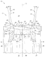
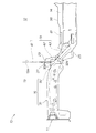
- FIG. 2 is a perspective view of a configuration in which a dashboard lower panel is removed from a front portion of the vehicle body shown in FIG. It is a side view of the structure which removed the side sill from the front part of the vehicle body shown in FIG.
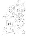
- FIG. 4 is a perspective view around a dashboard lower panel and a cross member shown in FIG. 3.
- FIG. 4 is a perspective view of a relationship among a cross member, a dashboard lower panel, and a reinforcing plate shown in FIG.
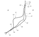
- FIG. 7 is a perspective view of a main part around a cross member and a joint cover shown in FIG. 6. It is the perspective view which looked at the cross member shown by FIG. 4 and the joint cover periphery from the engine room side.
- FIG. 5 is a perspective view of a main part around a cross member and a joint cover shown in FIG. 4. It is sectional drawing along the 11-11 line of FIG.
- FIG. 7 is a perspective view of the dashboard lower panel shown in FIG. 6 as viewed from the engine room side around the bead.
- FIG. 13 is a cross-sectional view taken along line 13-13 in FIG.
- FIG. 2 is a perspective view of a relationship between a left front side frame and a dashboard lower panel shown in FIG. 1 as viewed from the engine room side.
- FIG. 15 is a cross-sectional view taken along line 15-15 of FIG.
- the vehicle 10 is, for example, a passenger car, and a front engine room 13 and a vehicle room 12 positioned just behind the engine room 13 are formed inside the vehicle body 11. Yes.
- the vehicle body 11 is formed of a monocoque body, and is formed symmetrically with respect to a vehicle width center line CL that extends in the vehicle longitudinal direction through the center of the vehicle 10 in the vehicle width direction.
- the front half of the vehicle body 11 includes left and right side sills 14 and 14, left and right front side frames 16 and 16, a dashboard lower panel 19, left and right outriggers 25 and 25, and left and right floor frames 36 and 36. Including.
- the left and right front side frames 16, 16 are located on the left and right sides of the front portion of the vehicle body 11 (the portion in front of the dashboard lower panel 19) and extend in the front-rear direction of the vehicle body 11.
- the left and right outriggers 25, 25 extend from the rear ends of the left and right front side frames 16, 16 to the left and right side sills 14, 14 outward in the vehicle width direction.
- the left and right side sills 14, 14 are located on the left and right sides of the central portion of the vehicle body 11 (the portion behind the dashboard lower panel 19) and extend in the front-rear direction of the vehicle body 11.
- the dashboard lower panel 19 is positioned behind the left and right front side frames 16, 16 to partition the vehicle body 11 in front and rear, that is, the front engine room 13 and the rear It is a partition which partitions off between the vehicle interior 12 of this.
- the dashboard lower panel 19 includes a partition plate 41 in the upper half portion and an inclined plate 43 in the lower half portion.
- the partition plate 41 is formed in a substantially vertical flat plate shape positioned on the inclined portion 32 of the front side frame 16.
- the inclined plate 43 is inclined rearward and downward from the lower end of the partition plate 41.
- the rear end of the dashboard lower panel 19, that is, the rear end of the inclined plate 43 is coupled to the floor panel 37.
- the floor panel 37 is a substantially flat plate member that constitutes the floor of the vehicle compartment 12, and a center tunnel 38 extending in the longitudinal direction of the vehicle body is formed at the center of the vehicle width.
- the center tunnel 38 is curved in a substantially inverted U-shaped cross section that is convex upward from the floor panel 37.
- the left and right front side frames 16, 16 are substantially horizontal left and right horizontal portions 31, 31 positioned in front of the partition plate 41, and left and right horizontal portions 31, 31 inclined rearward and downward from the rear ends. Inclined portions 32, 32.
- the left and right floor frames 36, 36 extend rearward from the rear end portions 32 b, 32 b of the left and right front side frames 16, 16 and are located in the vehicle compartment 12, and are floor panels 37. Support.
- the left and right frame reinforcing plates 34, 34 overlap at least one of the left and right inclined portions 32, 32 and the left and right floor frames 36, 36 via the dashboard lower panel 19 or directly. (Including the covered structure) and bonded.
- the left and right frame reinforcing plates 34, 34 at least one of the left and right inclined portions 32, 32 and the left and right floor frames 36, 36 can be reinforced.
- the dashboard lower panel 19 has an upwardly convex front tunnel portion 47 extending rearward from the lower portion.
- the front tunnel portion 47 is formed from a corner 42 between the partition plate 41 and the inclined plate 43, that is, from the bent portion 42 to the inclined surface 43, and is located in the center of the vehicle width toward the vehicle compartment 12. It is curved in a substantially inverted U-shaped cross section that is convex upward.
- the partition plate 41 of the dashboard lower panel 19 has at least a surface facing the vehicle compartment 12 (a rear surface 19 a of the dashboard lower panel 19).
- a part, for example, generally the left half is reinforced by the reinforcing plate 28.
- the surface rigidity (the rigidity in the panel surface direction) of the partition plate 41 is increased.
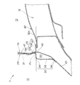
- the reinforcing plate 28 includes a reinforcing plate main body 91 that is overlapped and joined to the rear surface 19a of the partition plate 41, and a bent portion 92 (extension portion 92) that is bent at the lower end of the reinforcing plate main body 91. Is an integrally formed product.
- the extension 92 provided at the lower end of the reinforcing plate 28 extends from above the bent portion 42 of the partition plate 41 and the inclined plate 43 to the rear of the bent portion 42 and is joined to the inclined plate 43. Yes. As a result, the extended portion 92 and the dashboard lower panel 19 form a closed cross-sectional body 93 that is elongated in the vehicle width direction.
- the extension portion 92 is a member having a substantially inverted L shape in sectional view, and extends rearward from a higher position (higher point Pu) than the bent portion 42.
- a substantially horizontal horizontal plate 94 (extending portion 94), a vertical plate 95 (hanging portion 95) hanging substantially vertically from the rear end of the horizontal plate 94, and a rear lower side of the vertical plate 95.
- a flange 96 extending to.
- the horizontal plate 94 extends rearward while being generally along at least one of the upper surfaces 32a, 32a (upper walls 32a, 32a) of the left and right front side frames 16, 16.
- the vertical plate 95 is joined to the inclined plate 43 by joining the lower surface of the flange 96 to the upper surface of the inclined plate 43.
- the extension portion 92 is joined to the inclined portion 32 of the left front side frame 16 via the inclined surface 43 of the dashboard lower panel 19.
- the dashboard lower panel 19 has a joint cover 22 at a corner 42 between the partition plate 41 and the inclined plate 43, that is, a bent portion 42.
- the joint cover 22 is a generally tapered tapered hollow body extending forward and downward from the dashboard lower panel 19 toward the engine room 13. 52 is formed with an opening 51 through which the steering shaft 21 (see FIG. 4) of the steering device passes.
- the joint cover 22 includes a flat, substantially disk-shaped bottom portion 52 facing the front lower side, a step portion 53 rising from a side edge and a rear edge of the bottom portion 52, and a front edge of the bottom portion 52.
- the rear flange 56 is formed continuously with the front flange 55.
- the dashboard lower panel 19 is reinforced by a cross member 23 (dash cross member 23) superimposed on the rear surface 19a.
- the cross member 23 is an elongated member in the vehicle width direction, located at a corner 42 between the partition plate 41 and the inclined plate 43, that is, a bent portion 42. It is a letter-shaped member. That is, the cross member 23 extends in the vehicle width direction along the bent portion 42.
- the cross member 23 configured as described above is divided into two in the vehicle width direction from the portion located on the joint cover 22 as shown in FIGS. That is, the cross member 23 is composed of a two-part product of a left cross member 61 and a right cross member 62. However, the joint cover 22, the dashboard lower panel 19, and the cross member 23 are joined to each other so that the cross member 23 is integrated on the left and right.
- the cross member 23 can be configured by a single product equivalent to the configuration of the two-part product.
- the left cross member 61 includes a substantially inverted L-shaped member main body 63, an upper flange 64 extending upward from the upper end of the member main body 63, and the member main body 63. And a lower flange 65 extending downward and rearward from the lower end.
- the upper flange 64 is overlapped and joined to the partition plate 41 from the vehicle compartment 12.
- the lower flange 65 is overlapped and joined from the passenger compartment 12 to the upper surface of the inclined plate 43.
- the upper ends of the left cross member 61 and the right ends of the lower flanges 64 and 65 are joined to the joint cover 22 with the dashboard lower panel 19 interposed therebetween.
- the left end 67 (one end 67 in the vehicle width direction) of the left cross member 61 is formed in a substantially inverted L shape that matches the cross-sectional shape and size of one end 92a (right end 92a) of the extension 92.
- the one ends 67 and 92a are abutted or overlapped and joined. Since the one ends 67 and 92a have the same cross-sectional shape, they can be smoothly joined to each other.
- the right cross member 62 includes a substantially inverted L-shaped member main body 73, an upper flange 74 extending upward from the upper end of the member main body 73, and the member And a lower flange 75 extending downward from the lower end of the main body 73.
- the upper flange 74 is overlapped and joined to the partition plate 41 from the vehicle compartment 12.
- the lower flange 75 is overlapped and joined from the passenger compartment 12 to the upper surface of the inclined plate 43.
- the upper end of the right cross member 62 and the left end 76 of the lower flanges 74 and 75 are joined to the joint cover 22 with the dashboard lower panel 19 interposed therebetween.
- a right end 77 (right end 77 in the vehicle width direction) of the right cross member 62 is joined to the inclined portion 32 of the right front side frame 16 via the inclined surface 43 of the dashboard lower panel 19.
- the joint cover 22 and the left and right cross members 61 and 62 are provided on the bent portion 42 of the dashboard lower panel 19. Furthermore, the left and right cross members 61 and 62 are joined to the joint cover 22 with the dashboard lower panel 19 interposed therebetween. Therefore, originally, the strength of the dashboard lower panel 19 can be further improved by the synergistic effect of the highly rigid bent portion 42 (see FIG. 6), the joint cover 22 and the left and right cross members 61 and 62. it can.
- a combination of the cross member 23 including the left and right cross members 61 and 62 and the extension 92 constitutes one cross member that is substantially long in the vehicle width direction. That is, the extension part 92 is a kind of cross member.
- the extended section 92 and the dashboard lower panel 19 constitute a closed cross-sectional body 93 that is elongated in the vehicle width direction.
- a closed cross-section body 93 for reinforcing the bent portion 42 of the dashboard lower panel 19 with a simple configuration simply by combining the reinforcing plate 28 for increasing the surface rigidity of the partition plate 41 with the dashboard lower panel 19. Can be configured. There is no need to newly provide a reinforcing cross member. That is, by replacing the cross member with the configuration of the closed cross section 93, the rigidity of the dashboard lower panel 19 can be increased, and as a result, the rigidity of the vehicle body 11 can be increased. Therefore, the number of parts of the dashboard lower panel 19 and the members that reinforce the dashboard lower panel 19 can be suppressed as much as possible. Therefore, the rigidity of the dashboard lower panel 19 can be increased while reducing the weight of the vehicle body 11 and reducing the cost.
- the rigidity of the reinforcing plate 28 is increased by the closed cross-section body 93. Since the thickness of the reinforcing plate 28 itself can be reduced, the vehicle body 11 can be further reduced in weight. In addition, by reducing the thickness of the reinforcing plate 28, the formability of the reinforcing plate 28 itself is also increased.
- the collision force transmitted from the front to the rear of the right front side frame 16 is transmitted to the right cross member 62 as indicated by an arrow a1, and further from the right cross member 62 as indicated by an arrow a2. It is transmitted to the joint cover 22 and is transmitted to the left cross member 61 as indicated by an arrow a5 through the periphery of the bottom 52 as indicated by arrows a3 and a4.
- the extension 92 for constituting the closed cross-section body 93 in combination with the dashboard lower panel 19 is formed in a substantially inverted L shape in cross-section. Yes.
- the horizontal plate 94 forming the upper side of the inverted L-shape extends rearward while being generally along at least one of the upper surfaces 32, 32 of the left and right front side frames 16, 16. For this reason, when a so-called frontal collision occurs where a collision force acts on the front surface of the vehicle 10, the collision force from the front is transmitted from the front end of the front side frame 16 to the rear, and further on the extension of the front side frame 16. It is transmitted to the horizontal plate 94 located at. Therefore, the extension portion 92 can efficiently receive the collision force from the front side frame 16 and distribute it around the vehicle body 11.
- the left cross member 61 is formed at the upper portion of the upwardly projecting tunnel portion 47 formed at the lower portion of the dashboard lower panel 19 and the dashboard.
- the lower panel 19 is provided on the rear surface 19a. More specifically, the left cross member 61 has a curved portion 68 that is curved so as to protrude upward along the tunnel portion 47.
- Such a left cross member 61 can be configured by a separate member from the dashboard lower panel 19 and the tunnel portion 47 provided in the dashboard lower panel 19. For this reason, even if the cross member 23 has a shape along the convex shape of the tunnel portion 47, it can be easily formed by a general molding method such as press molding. Therefore, regardless of the relative positional deviation (including the height deviation) of the tunnel part 47 with respect to the extension part 92, the joining position (including the height) of the cross member 23 joined to the extension part 92 is included. ) Can be set to be optimal. Furthermore, since the cross member 23 is joined to the extension portion 92, the length of the cross member 23 can be shortened accordingly.
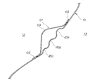
- the dashboard lower panel 19 has a plurality of beads 45a to 45c at a portion covered by the left cross member 61.
- the plurality of beads 45a to 45c are formed elongated in the dashboard lower panel 19 along the longitudinal direction of the left cross member 61, and are arranged vertically.
- the beads 45a to 45c improve the load transmission rate of the dash cross member 23 in the vehicle width direction (left-right direction).
- the plurality of beads 45 a to 45 c may be provided at a portion covered with the right cross member 62 and along the longitudinal direction of the right cross member 62.
- the inclined portions 32, 32 of the left and right front side frames 16 are curved while projecting from the rear ends of the horizontal portions 31, 31 to the center of the vehicle width and toward the rear of the vehicle body. It extends to.
- the portions that are most convex toward the center of the vehicle width are referred to as convex portions 33, 33.
- the cross member 23 is disposed in the vicinity of the left and right convex portions 33 and 33. Therefore, the left and right front side frames 16 and 16 are prevented from bending, and the load from the front transmitted from the left and right front side frames 16 and 16 is transmitted via the joint cover 22 and the left and right cross members 61 and 62. Can be transmitted to the rear of the vehicle body 11.
- the cross member 23 is provided on the surface 19a (rear surface 19a) facing the vehicle compartment 12 of the dashboard lower panel 19. For this reason, when a gear box of an electric steering device (not shown) is mounted in the engine room 13, the gear box can be disposed close to the dashboard lower panel 19. Accordingly, the length of the engine room 13 can be reduced. Therefore, it is easy to realize a so-called short overhang vehicle in which the length from the front end of the vehicle 10 to the front wheels (not shown) is set short.
- the partition plate 41 of the dashboard lower panel 19 has a portion on which a brake booster BK (see FIG. 6) for adjusting the brake operation force by the driver is attached by bolting. Reinforced by the reinforcing member 27.
- the panel reinforcing member 27 is overlapped and joined to the rear surface of the partition plate 41, that is, the surface 19 a (rear surface 19 a) facing the passenger compartment 12 of the dashboard lower panel 19.
- the brake booster BK is well known for increasing the brake braking force by, for example, boosting the depression force of the brake pedal using a predetermined negative pressure when the driver depresses a brake pedal (not shown). Consists of devices.
- the panel reinforcing member 27 is separated from the cross member 23. For this reason, when the cross member 23 is displaced rearward or / and deformed by a collision force from the front, the panel reinforcing member 27 is not easily affected by the cross member 23. As a result, the brake booster BK is also affected. It is hard to receive.
- the inclined portions 32 and 32 of the left and right front side frames 16 and 16 are joined to the partition plate 41 by left and right brackets 29 and 29.
- the left and right brackets 29 and 29 are formed symmetrically with respect to the vehicle width center line CL.
- the inclined portion 32 of the left front side frame 16 of the left and right front side frames 16, 16 is It is located in the vicinity of the horizontal plate 94.
- the inclined portion 32 of the left front side frame 16 is joined to the partition plate 41 and the reinforcing plate 28 by a bracket 29 located in the vicinity of the horizontal plate 94. That is, the left bracket 29 is joined to the upper surface 32a (upper wall 32a) of the left inclined portion 32. Therefore, the collision force from the front of the vehicle body 11 is transmitted from the inclined portion 32 of the left front side frame 16 to the partition plate 41, the reinforcing plate 28, and the closed cross-section body 93 via the left bracket 29. Therefore, although the rear part of the left front side frame 16 is inclined, the extension part 92 of the reinforcing plate 28 can sufficiently receive the collision force from the inclined part 32.
- the left bracket 29 is a substantially L-shaped member in cross-sectional view, and is an integrally molded product including a first joint portion 101 having a horizontal plate shape, a second joint portion 105 having a vertical plate shape, and a rib 106.
- first joint portion 101 is joined to at least one of the upper surfaces 32a, 32a of the left and right inclined portions 32, 32.
- the second joint 105 is erected from the rear end of the first joint 101 and joined to the partition plate 41 and the reinforcing plate 28.
- the rib 106 protrudes from the front end of the first joint 101 to the second joint 105. Further, the rib 106 is located at the inner end of the first joint portion 101 in the vehicle width direction.
- the left bracket 29 has joint portions 102 and 103 at both ends in the vehicle width direction of the first joint portion 101.
- the first joint portion 102 stands up from the outer end of the first joint portion 101 in the vehicle width direction and is joined to the upper flange 32c of the left inclined portion 32.
- the second joint portion 103 hangs down from the inner end in the vehicle width direction of the first joint portion 101 and is joined to the inner surface 32e (inner wall 32e) of the left inclined portion 32.
- the left bracket 29 is formed into a highly rigid member by being formed in a substantially L shape in sectional view in which deformation is restricted by the rib 106. For this reason, the bracket 29 can sufficiently transmit the collision force transmitted from the inclined portion 32 to the partition plate 41, the reinforcing plate 28, and the closed cross-section body 93.
- the right cross member 62 has an upper surface 73 a (upper wall 73 a) of a substantially inverted L-shaped member body 73 substantially with respect to the lateral plate 94 of the extension 92. It is set to the same height.
- the inclined portion 32 and the right bracket 29 of the right front side frame 16 are located in the vicinity of the upper surface 73 a of the member main body 73.
- the right inclined portion 32 is joined to the partition plate 41 and the right cross member 62 by the right bracket 29. That is, the right bracket 29 is joined to the upper surface 32a of the right inclined portion 32 in substantially the same manner as the left bracket 29 shown in FIGS.
- the collision force from the front of the vehicle body 11 is transmitted from the inclined portion 32 of the right front side frame 16 to the partition plate 41 and the right cross member 62 via the right bracket 29. Accordingly, the cross member 23 can sufficiently receive the collision force from the inclined portion 32 even though the rear portion of the right front side frame 16 is inclined.
- a high-strength plate 26 having a higher strength than the inclined plate 43 is provided at least at the center of the vehicle width at the rear end of the inclined plate 43 of the dashboard lower panel 19.
- the high-strength plate 26 is made of, for example, a plate material made of a high-tensile steel plate. More specifically, the high-strength plate 26 is overlapped and joined to the upper surface or the lower surface at least in the center of the vehicle width at the rear end of the inclined plate 43. Alternatively, at least the center of the vehicle width at the rear end of the inclined plate 43 is cut out, and the high-strength plate 26 is fitted or covered in the cut-out portion and joined.
- the inclined plate 43 has an intermediate portion 46 (see FIG. 3) sandwiched between the cross member 23 and the high-strength plate 26.
- the intermediate portion 46 is a so-called fragile portion having rigidity and strength smaller than those of the cross member 23 and the high-strength plate 26. More specifically, the upper end portion of the inclined plate 43 is reinforced by the cross member 23 to be configured with high rigidity and high strength. Further, the rear end portion of the inclined plate 43 is reinforced by the high-strength plate 26, thereby being configured with high rigidity and high strength. For this reason, in the inclined plate 43, the intermediate portion 46 sandwiched between the cross member 23 and the high-strength plate 26 is a fragile portion configured to be less rigid and stronger than other portions not sandwiched. It becomes.
- the intermediate portion 46 is appropriately referred to as a “fragile portion 46”.
- the high-strength plate 26 is stretched between the rear portions of the left and right front side frames 16 and 16. For this reason, since the rear end portion of the inclined plate 43 of the dashboard lower panel 19 is further strengthened, the deformation performance of the fragile portion 46 by the collision force can be further enhanced. As a result, the entire dashboard lower panel 19 can be further prevented from being deformed rearward.
- the dashboard lower panel 19 includes an upward convex front tunnel portion 47 extending rearward from the lower portion.
- the high-strength plate 26 is made of a high-strength steel plate, and has an upward convex rear tunnel portion 81 that is positioned directly behind the front tunnel portion 47 and formed integrally therewith.
- the rear tunnel portion 81 is connected to the rear end of the front tunnel portion 47 and extends rearward. Since the high-strength plate 26 is only composed of a high-strength steel plate, the rear tunnel portion 81 can be easily formed by press molding. And since it is the rear tunnel part 81 comprised by the high-tensile steel plate, intensity
- a cross member 35 (front cross member 35) is stretched between the rear portions of the left and right front side frames 16, 16.
- the front edge 35a of the front cross member 35 is formed in a substantially arch shape that is curved as a whole so that the center of the vehicle width is located behind the both ends in the vehicle width direction.
- the front cross member 35 includes a main body member 83 located at the center of the vehicle width, and left and right connection members 84 and 85 joined to both ends of the main body member 83 in the vehicle width direction.
- the main body member 83 is formed in a convex shape along the inner surface of the center tunnel 38 protruding from the floor panel 37 into the passenger compartment 12 (surface opposite to the passenger compartment 12).
- the left end 84a of the left connecting member 84 in the vehicle width direction is joined to the lower wall 32d of the inclined portion 32 of the left front side frame 16.
- An inner end 84 b of the left connecting member 84 in the vehicle width direction is joined to the left end of the high-strength plate 26.
- the rear end 84 c of the left connection member 84 is joined to the rear end 26 c of the inclined plate 43 of the dashboard lower panel 19.
- An end 85a on the outer side in the vehicle width direction of the right connection member 85 is joined to the lower wall 32d of the inclined portion 32 of the right front side frame 16.
- An inner end 85 b of the right connection member 85 in the vehicle width direction is coupled to the right end of the high-strength plate 26.
- the rear end 85 c of the right connection member 85 is joined to the rear end 26 c of the inclined plate 43 of the dashboard lower panel 19.
- the high-strength plate 26 is joined to the front cross member 35 along the front edge 35a. Since the front edge 35a has a substantially arch shape, the edge length is longer than when the front edge 35a is linear in the vehicle width direction. For this reason, the joining length between the high-strength plate 26 and the front cross member 35 can be set long, or many joining locations can be set. Accordingly, the total joint area can be increased, and the strength of the entire joint portion (including the shear strength in the longitudinal direction of the vehicle body 11) is increased. As a result, the strength of the vehicle body 11 can be further increased.
- the vehicle body 11 of the present invention is suitable for use in passenger cars such as sedans and wagons.
Landscapes
- Engineering & Computer Science (AREA)
- Chemical & Material Sciences (AREA)
- Combustion & Propulsion (AREA)
- Transportation (AREA)
- Mechanical Engineering (AREA)
- Body Structure For Vehicles (AREA)
Abstract
Description
図1~図3及び図6に示されるように、ダッシュボードロアパネル19は、下部から後方へ延びた、上に凸状の前部トンネル部47を有する。該前部トンネル部47は、区画板41と該傾斜板43との間のコーナ42、つまり屈曲部42から傾斜面43にかけて形成されており、車幅中央に位置し、車室12へ向かって上に凸状となる、略逆U字状断面に湾曲している。
Claims (11)
- 車体の前部の左右両側に位置して該車体の前後方向に延びる左右のフロントサイドフレームと、前記左右フロントサイドフレームの後に位置して前記車体を前後に区画するダッシュボードロアパネルと、を含む車体前部構造において、
前記ダッシュボードロアパネルは、前記車体を前後に区画するように形成された縦板状の区画板と、該区画板の下端から後下方へ傾斜した傾斜板と、を含み、
前記区画板は、後面の少なくとも一部が補強板によって補強され、
該補強板は、下端に延長部を有し、
該延長部は、前記区画板と前記傾斜板との屈曲部よりも上から、該屈曲部よりも後へ延びて、前記傾斜板に接合され、
前記延長部と前記ダッシュボードロアパネルとによって車幅方向に細長い閉断面体が構成されている、ことを特徴とする車体前部構造。 - 前記ダッシュボードロアパネルの下部から後方へ延びて上に凸状のトンネル部と、
前記トンネル部の凸形状に沿いつつ車幅方向へ延びて、前記トンネル部の上部に且つ前記ダッシュボードロアパネルの後面に設けられた、車幅方向に延びるクロスメンバと、を更に有し、
該クロスメンバは、前記延長部に接合されている、請求項1記載の車体前部構造。 - 前記延長部は、略逆L字状の断面形状を有し、
前記屈曲部よりも上位から、前記左右のフロントサイドフレームの上面の少なくとも一方に概ね沿いつつ後方へ延びている横板と、
該横板の後端から垂下して前記傾斜板に接合される縦板と、
から成る、請求項1又は請求項2記載の車体前部構造。 - 前記クロスメンバの車幅方向の一端は、前記延長部の車幅方向の一端の断面形状に合わせた形状に形成されるとともに、前記一端同士が接合されている、請求項2記載の車体前部構造。
- 前記左右のフロントサイドフレームは、前記区画板よりも前に位置する略水平な左右の水平部と、該左右の水平部の後端から後下方へ傾斜した左右の傾斜部と、から成り、
前記左右のフロントサイドフレームのなかで、前記横板の近傍に位置する方のフロントサイドフレームの前記傾斜部は、前記横板の近傍に位置するブラケットによって前記区画板及び前記補強板に接合されている、請求項3記載の車体前部構造。 - 前記ブラケットは、略L字状の断面形状を有し、
前記左右の傾斜部の上面の少なくとも一方に接合される横板状の第1接合部と、
該第1接合部から起立して前記区画板及び前記補強板に接合される縦板状の第2接合部と、
前記第1接合部から前記第2接合部にわたって連なるように隆起したリブと、から成る、請求項5記載の車体前部構造。 - 前記ダッシュボードロアパネルは、前記屈曲部に沿って車幅方向に延びるクロスメンバにより補強され、
前記ダッシュボードロアパネルの前記傾斜板の後端の車幅中央には、該傾斜板よりも高強度の高強度板が設けられ、
前記傾斜板は、前記クロスメンバと前記高強度板とによって挟まれている中間部分が、挟まれていない他の部分よりも脆弱である、請求項1記載の車体前部構造。 - 前記区画板は、運転者によるブレーキ操作力を調整するためのブレーキブースタが取り付けられる部分を、パネル補強部材によって補強され、
該パネル補強部材は、前記クロスメンバから分離している、請求項7記載の車体前部構造。 - 前記高強度板は、前記左右のフロントサイドフレームの後部間に掛け渡されている、請求項7又は請求項8記載の車体前部構造。
- 前記ダッシュボードロアパネルは、下部から後方へ延びて上に凸状の前部トンネル部を備え、
前記高強度板は、高張力鋼板によって構成されており、前記前部トンネル部の真後ろに位置した、上に凸状の後部トンネル部が一体に形成され、
該後部トンネル部は、前記前部トンネル部の後端に連なって後方へ延びている、請求項7から請求項9までのいずれか1項記載の車体前部構造。 - 前記左右のフロントサイドフレームの後部間に掛け渡されているフロントクロスメンバを、更に備え、
該フロントクロスメンバの前縁は、車幅中央が車幅方向の両端よりも後方に位置するように全体に湾曲した、略アーチ状に形成され、
前記フロントクロスメンバには、前記前縁に沿って前記高強度板が接合されている、請求項7から請求項10までのいずれか1項記載の車体前部構造。
Priority Applications (4)
| Application Number | Priority Date | Filing Date | Title |
|---|---|---|---|
| JP2012519328A JP5560329B2 (ja) | 2010-06-10 | 2011-05-24 | 車体前部構造 |
| EP11792278.1A EP2543575B1 (en) | 2010-06-10 | 2011-05-24 | Structure for front section of vehicle body |
| CN201180012281.7A CN102791566B (zh) | 2010-06-10 | 2011-05-24 | 车身前部构造 |
| US13/702,604 US8702148B2 (en) | 2010-06-10 | 2011-05-24 | Structure for front section of vehicle body |
Applications Claiming Priority (4)
| Application Number | Priority Date | Filing Date | Title |
|---|---|---|---|
| JP2010133025 | 2010-06-10 | ||
| JP2010-133025 | 2010-06-10 | ||
| JP2010133037 | 2010-06-10 | ||
| JP2010-133037 | 2010-06-10 |
Publications (1)
| Publication Number | Publication Date |
|---|---|
| WO2011155321A1 true WO2011155321A1 (ja) | 2011-12-15 |
Family
ID=45097929
Family Applications (1)
| Application Number | Title | Priority Date | Filing Date |
|---|---|---|---|
| PCT/JP2011/061837 Ceased WO2011155321A1 (ja) | 2010-06-10 | 2011-05-24 | 車体前部構造 |
Country Status (5)
| Country | Link |
|---|---|
| US (1) | US8702148B2 (ja) |
| EP (1) | EP2543575B1 (ja) |
| JP (1) | JP5560329B2 (ja) |
| CN (1) | CN102791566B (ja) |
| WO (1) | WO2011155321A1 (ja) |
Cited By (4)
| Publication number | Priority date | Publication date | Assignee | Title |
|---|---|---|---|---|
| JP2013159156A (ja) * | 2012-02-02 | 2013-08-19 | Nissan Motor Co Ltd | 車体前部構造 |
| JP2013216150A (ja) * | 2012-04-05 | 2013-10-24 | Honda Motor Co Ltd | 車体前部構造 |
| JP2018188014A (ja) * | 2017-05-08 | 2018-11-29 | マツダ株式会社 | 車両の前部車体構造 |
| JP2024518017A (ja) * | 2021-06-29 | 2024-04-24 | ビーワイディー カンパニー リミテッド | 車体フレーム及びそれを有する車両 |
Families Citing this family (16)
| Publication number | Priority date | Publication date | Assignee | Title |
|---|---|---|---|---|
| DE102011103090A1 (de) * | 2011-05-25 | 2012-11-29 | Thyssenkrupp Steel Europe Ag | Fahrzeugkarosserie und deren Verwendung |
| JP5664497B2 (ja) * | 2011-08-10 | 2015-02-04 | トヨタ自動車株式会社 | 車両前部構造 |
| FR2989053B1 (fr) * | 2012-04-05 | 2014-03-21 | Renault Sa | Chassis d'un vehicule automobile comprenant des moyens d'absorption d'un choc frontal |
| US8876132B2 (en) * | 2012-09-28 | 2014-11-04 | Ford Global Technologies, Llc | Front end assembly for vehicle chassis |
| JP6066315B2 (ja) * | 2013-05-09 | 2017-01-25 | スズキ株式会社 | 車両前部構造 |
| US9440682B2 (en) | 2013-06-28 | 2016-09-13 | GM Global Technology Operations LLC | Outward splayed mixed material longitudinal rail system |
| JP6011583B2 (ja) * | 2014-07-04 | 2016-10-19 | トヨタ自動車株式会社 | 車両下部構造 |
| JP6522982B2 (ja) * | 2015-02-18 | 2019-05-29 | 本田技研工業株式会社 | 車体構造 |
| US10118647B2 (en) * | 2015-03-17 | 2018-11-06 | Honda Motor Co., Ltd. | Vehicle body structure |
| BR112017026900A8 (pt) * | 2015-06-26 | 2023-01-17 | Honda Motor Co Ltd | Estrutura dianteira de corpo de veículo |
| KR101786673B1 (ko) * | 2015-12-14 | 2017-10-18 | 현대자동차 주식회사 | 전방 차체 구조 |
| US10077012B2 (en) * | 2016-11-15 | 2018-09-18 | Ford Global Technologies, Llc | Localized silicone heat shielding for extension dash panels |
| JP6532513B2 (ja) * | 2017-09-15 | 2019-06-19 | 本田技研工業株式会社 | 車体構造 |
| KR102621715B1 (ko) | 2019-02-01 | 2024-01-08 | 현대자동차주식회사 | 차량용 격벽구조 |
| CN113086013B (zh) * | 2021-04-23 | 2022-07-22 | 云度新能源汽车有限公司 | 一种电动汽车前围结构 |
| KR20230090717A (ko) * | 2021-12-15 | 2023-06-22 | 현대자동차주식회사 | 차체 전방 구조 |
Citations (9)
| Publication number | Priority date | Publication date | Assignee | Title |
|---|---|---|---|---|
| JPH01169482U (ja) * | 1988-05-20 | 1989-11-29 | ||
| JPH0474185U (ja) * | 1990-11-09 | 1992-06-29 | ||
| JPH0867273A (ja) * | 1994-08-31 | 1996-03-12 | Toyota Motor Corp | 電気自動車における電力線の配設構造 |
| JPH1045034A (ja) | 1996-08-05 | 1998-02-17 | Toyota Motor Corp | 車体前部構造 |
| JP2001030954A (ja) * | 1999-07-21 | 2001-02-06 | Nissan Motor Co Ltd | 自動車の車体前部構造 |
| JP2004090818A (ja) * | 2002-09-02 | 2004-03-25 | Toyota Motor Corp | 車体前部構造 |
| JP2006117097A (ja) * | 2004-10-21 | 2006-05-11 | Toyota Motor Corp | アクセルペダル取付部の構造 |
| JP2007030627A (ja) | 2005-07-25 | 2007-02-08 | Mazda Motor Corp | 自動車の前部車体構造 |
| JP2009073305A (ja) * | 2007-09-20 | 2009-04-09 | Honda Motor Co Ltd | ブレーキマスタシリンダ取付構造 |
Family Cites Families (7)
| Publication number | Priority date | Publication date | Assignee | Title |
|---|---|---|---|---|
| US4804222A (en) * | 1985-10-31 | 1989-02-14 | Mazda Motor Corporation | Front structure of vehicle body |
| JPH0544230Y2 (ja) * | 1987-07-10 | 1993-11-09 | ||
| JP2852424B2 (ja) | 1987-12-25 | 1999-02-03 | 株式会社エンプラス | 照明装置 |
| JPH0474185A (ja) | 1990-07-13 | 1992-03-09 | Toshiba Silicone Co Ltd | 3―グリシドキシプロピルトリス(トリオルガノシロキシ)シランの製造方法 |
| CN101434264B (zh) * | 2007-11-15 | 2010-10-06 | 比亚迪股份有限公司 | 车辆的地板总成 |
| JP2009234495A (ja) * | 2008-03-28 | 2009-10-15 | Mazda Motor Corp | 自動車のフレーム構造 |
| JP4677025B2 (ja) * | 2008-10-30 | 2011-04-27 | 本田技研工業株式会社 | 車体前部構造 |
-
2011
- 2011-05-24 WO PCT/JP2011/061837 patent/WO2011155321A1/ja not_active Ceased
- 2011-05-24 CN CN201180012281.7A patent/CN102791566B/zh not_active Expired - Fee Related
- 2011-05-24 EP EP11792278.1A patent/EP2543575B1/en not_active Not-in-force
- 2011-05-24 US US13/702,604 patent/US8702148B2/en active Active
- 2011-05-24 JP JP2012519328A patent/JP5560329B2/ja not_active Expired - Fee Related
Patent Citations (9)
| Publication number | Priority date | Publication date | Assignee | Title |
|---|---|---|---|---|
| JPH01169482U (ja) * | 1988-05-20 | 1989-11-29 | ||
| JPH0474185U (ja) * | 1990-11-09 | 1992-06-29 | ||
| JPH0867273A (ja) * | 1994-08-31 | 1996-03-12 | Toyota Motor Corp | 電気自動車における電力線の配設構造 |
| JPH1045034A (ja) | 1996-08-05 | 1998-02-17 | Toyota Motor Corp | 車体前部構造 |
| JP2001030954A (ja) * | 1999-07-21 | 2001-02-06 | Nissan Motor Co Ltd | 自動車の車体前部構造 |
| JP2004090818A (ja) * | 2002-09-02 | 2004-03-25 | Toyota Motor Corp | 車体前部構造 |
| JP2006117097A (ja) * | 2004-10-21 | 2006-05-11 | Toyota Motor Corp | アクセルペダル取付部の構造 |
| JP2007030627A (ja) | 2005-07-25 | 2007-02-08 | Mazda Motor Corp | 自動車の前部車体構造 |
| JP2009073305A (ja) * | 2007-09-20 | 2009-04-09 | Honda Motor Co Ltd | ブレーキマスタシリンダ取付構造 |
Non-Patent Citations (1)
| Title |
|---|
| See also references of EP2543575A4 |
Cited By (4)
| Publication number | Priority date | Publication date | Assignee | Title |
|---|---|---|---|---|
| JP2013159156A (ja) * | 2012-02-02 | 2013-08-19 | Nissan Motor Co Ltd | 車体前部構造 |
| JP2013216150A (ja) * | 2012-04-05 | 2013-10-24 | Honda Motor Co Ltd | 車体前部構造 |
| JP2018188014A (ja) * | 2017-05-08 | 2018-11-29 | マツダ株式会社 | 車両の前部車体構造 |
| JP2024518017A (ja) * | 2021-06-29 | 2024-04-24 | ビーワイディー カンパニー リミテッド | 車体フレーム及びそれを有する車両 |
Also Published As
| Publication number | Publication date |
|---|---|
| JP5560329B2 (ja) | 2014-07-23 |
| JPWO2011155321A1 (ja) | 2013-08-01 |
| CN102791566B (zh) | 2015-04-15 |
| EP2543575A1 (en) | 2013-01-09 |
| CN102791566A (zh) | 2012-11-21 |
| EP2543575A4 (en) | 2013-09-18 |
| EP2543575B1 (en) | 2014-06-11 |
| US8702148B2 (en) | 2014-04-22 |
| US20130088048A1 (en) | 2013-04-11 |
Similar Documents
| Publication | Publication Date | Title |
|---|---|---|
| JP5560329B2 (ja) | 車体前部構造 | |
| JP4486996B2 (ja) | 車体構造 | |
| JP4677025B2 (ja) | 車体前部構造 | |
| US9884649B2 (en) | Lower vehicle-body structure of automotive vehicle | |
| US8702158B2 (en) | Structure for vehicle body front portion | |
| CN102656080B (zh) | 车身底板构造 | |
| US8485591B2 (en) | Front vehicle body structure | |
| WO2019198753A1 (ja) | 自動車の車体構造 | |
| US20130207417A1 (en) | Structure of front section of vehicle body | |
| CN112477998A (zh) | 车辆的车身结构 | |
| JP5427699B2 (ja) | 車体前部構造 | |
| CN105313981A (zh) | 用于机动车车身的车尾侧的加固结构 | |
| EP2371680B1 (en) | Front vehicle body structure | |
| CN107021136A (zh) | 车身前部结构 | |
| JP4853080B2 (ja) | 自動車の車体構造 | |
| US8960759B2 (en) | Vehicle body front structure | |
| JP5292245B2 (ja) | 車体の前突荷重支持体 | |
| WO2018029941A1 (ja) | 車体構造 | |
| JP2018127225A (ja) | 車体構造 | |
| JP6441631B2 (ja) | 車体構造 | |
| JP4592399B2 (ja) | 車両のフロントピラー構造 | |
| WO2019198752A1 (ja) | 自動車の車体構造 | |
| WO2019198751A1 (ja) | 自動車の車体構造 | |
| CN114056438A (zh) | 车身前部构造 | |
| JP2009107387A (ja) | 自動車の車体構造 |
Legal Events
| Date | Code | Title | Description |
|---|---|---|---|
| WWE | Wipo information: entry into national phase |
Ref document number: 201180012281.7 Country of ref document: CN |
|
| 121 | Ep: the epo has been informed by wipo that ep was designated in this application |
Ref document number: 11792278 Country of ref document: EP Kind code of ref document: A1 |
|
| WWE | Wipo information: entry into national phase |
Ref document number: 2012519328 Country of ref document: JP |
|
| WWE | Wipo information: entry into national phase |
Ref document number: 2011792278 Country of ref document: EP |
|
| WWE | Wipo information: entry into national phase |
Ref document number: 13702604 Country of ref document: US |
|
| NENP | Non-entry into the national phase |
Ref country code: DE |