WO2011155729A2 - 기둥형 집광장치를 구비한 태양 위치 추적 장치 - Google Patents
기둥형 집광장치를 구비한 태양 위치 추적 장치 Download PDFInfo
- Publication number
- WO2011155729A2 WO2011155729A2 PCT/KR2011/004068 KR2011004068W WO2011155729A2 WO 2011155729 A2 WO2011155729 A2 WO 2011155729A2 KR 2011004068 W KR2011004068 W KR 2011004068W WO 2011155729 A2 WO2011155729 A2 WO 2011155729A2
- Authority
- WO
- WIPO (PCT)
- Prior art keywords
- solar
- energy
- amount
- solar energy
- column
- Prior art date
- Legal status (The legal status is an assumption and is not a legal conclusion. Google has not performed a legal analysis and makes no representation as to the accuracy of the status listed.)
- Ceased
Links
Images


Classifications
-
- F—MECHANICAL ENGINEERING; LIGHTING; HEATING; WEAPONS; BLASTING
- F24—HEATING; RANGES; VENTILATING
- F24S—SOLAR HEAT COLLECTORS; SOLAR HEAT SYSTEMS
- F24S50/00—Arrangements for controlling solar heat collectors
- F24S50/20—Arrangements for controlling solar heat collectors for tracking
-
- G—PHYSICS
- G01—MEASURING; TESTING
- G01S—RADIO DIRECTION-FINDING; RADIO NAVIGATION; DETERMINING DISTANCE OR VELOCITY BY USE OF RADIO WAVES; LOCATING OR PRESENCE-DETECTING BY USE OF THE REFLECTION OR RERADIATION OF RADIO WAVES; ANALOGOUS ARRANGEMENTS USING OTHER WAVES
- G01S3/00—Direction-finders for determining the direction from which infrasonic, sonic, ultrasonic or electromagnetic waves, or particle emission, not having a directional significance, are being received
- G01S3/78—Direction-finders for determining the direction from which infrasonic, sonic, ultrasonic or electromagnetic waves, or particle emission, not having a directional significance, are being received using electromagnetic waves other than radio waves
- G01S3/782—Systems for determining direction or deviation from predetermined direction
- G01S3/783—Systems for determining direction or deviation from predetermined direction using amplitude comparison of signals derived from static detectors or detector systems
-
- G—PHYSICS
- G01—MEASURING; TESTING
- G01S—RADIO DIRECTION-FINDING; RADIO NAVIGATION; DETERMINING DISTANCE OR VELOCITY BY USE OF RADIO WAVES; LOCATING OR PRESENCE-DETECTING BY USE OF THE REFLECTION OR RERADIATION OF RADIO WAVES; ANALOGOUS ARRANGEMENTS USING OTHER WAVES
- G01S3/00—Direction-finders for determining the direction from which infrasonic, sonic, ultrasonic or electromagnetic waves, or particle emission, not having a directional significance, are being received
- G01S3/78—Direction-finders for determining the direction from which infrasonic, sonic, ultrasonic or electromagnetic waves, or particle emission, not having a directional significance, are being received using electromagnetic waves other than radio waves
- G01S3/782—Systems for determining direction or deviation from predetermined direction
- G01S3/785—Systems for determining direction or deviation from predetermined direction using adjustment of orientation of directivity characteristics of a detector or detector system to give a desired condition of signal derived from that detector or detector system
- G01S3/786—Systems for determining direction or deviation from predetermined direction using adjustment of orientation of directivity characteristics of a detector or detector system to give a desired condition of signal derived from that detector or detector system the desired condition being maintained automatically
- G01S3/7861—Solar tracking systems
-
- Y—GENERAL TAGGING OF NEW TECHNOLOGICAL DEVELOPMENTS; GENERAL TAGGING OF CROSS-SECTIONAL TECHNOLOGIES SPANNING OVER SEVERAL SECTIONS OF THE IPC; TECHNICAL SUBJECTS COVERED BY FORMER USPC CROSS-REFERENCE ART COLLECTIONS [XRACs] AND DIGESTS
- Y02—TECHNOLOGIES OR APPLICATIONS FOR MITIGATION OR ADAPTATION AGAINST CLIMATE CHANGE
- Y02E—REDUCTION OF GREENHOUSE GAS [GHG] EMISSIONS, RELATED TO ENERGY GENERATION, TRANSMISSION OR DISTRIBUTION
- Y02E10/00—Energy generation through renewable energy sources
- Y02E10/40—Solar thermal energy, e.g. solar towers
- Y02E10/47—Mountings or tracking
Definitions
- the present invention relates to a solar position tracking device that accurately tracks the position of the sun that changes every moment by the rotation of the earth. More particularly, the present invention includes a column condenser, a solar energy absorbing device, and an absorbed solar energy measuring device. A device that effectively tracks the sun.
- the conventional solar position tracking device to track the position of the sun with a device configured to vary the amount of energy absorbed by the energy absorbing device, such as a plurality of solar sensors, solar cells or photodiodes absorbing solar energy.
- a device configured to vary the amount of energy absorbed by the energy absorbing device, such as a plurality of solar sensors, solar cells or photodiodes absorbing solar energy.
- Korean Patent 10-0836870 measures the amount of energy incident on a plurality of identically shaped solar sensors installed on the bottom of a perforated cylinder, and measures the position of the sun by comparing and measuring the current generated from each sensor. When the solar cell is perpendicular to the sun or directly incident to the sun, a larger current value is obtained. When the tracking device is moved to have the same current value of each solar sensor, the sun is determined to be perpendicular to the tracking device.
- Korean Patent 10-0904243 has a partition between the light sensor to detect the sun.
- this method has a problem in that the position tracking of the sun is impossible because the difference in the amount of energy generated by each energy absorbing device is small when sunlight is weak or the sun is covered by clouds, such as morning or evening.
- Korean Patent 10-0427690 relates to a cylindrical solar position tracking device equipped with a convex lens on the top surface and four photodiodes installed on the bottom surface, so that the sunlight condensed through the lens shines on four photodiodes equally. Will move.
- Korean Patent 10-0933661 includes a technique for tracking the position of the sun using a lens unit and a photodiode using a refractive lens and a convex lens. The focus of sunlight collected through the lens is irradiated to four photodiodes to compare the values.
- the prior art may attach a separate sensor to determine the presence of sunlight.
- the present invention is directed to a column collector and a unit absorber plate of a solar energy absorber and an absorber installed at a focal trajectory on the rear side to transmit, refract, and concentrate sunlight. It provides a device that measures and compares the amount of energy absorbed to track the position of the sun.
- the light absorbing plate since the amount of solar energy absorbed by the focused absorbing plate and the non-condensing absorbing plate is significantly different since the light collecting device is installed, the light absorbing plate operates accurately in the weak sunlight such as morning and evening, and occurs in each absorbing plate. Comparing the amount of energy used, the sun can be determined whether the sun is present or not, and the condenser has no mechanical moving parts and can always track the sun's position.
- the solar light is collected by the column type light collecting device and the collected sunlight is absorbed by the energy absorbing plates
- the amount of energy absorbed by each of the absorbing plates is compared, and the presence or absence and orientation of the sunlight hardly and accurately determine altitude.
- each absorber shows a similar amount of energy or energy ratio, it means that there is no sunlight, and if there is a difference in the amount of energy, it means that there is sunlight.
- the difference in the amount of energy occurs as mentioned above, and the sun is concentrated in the absorber that shows the greatest amount of energy.
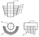
- FIG. 2 is a perspective view of an embodiment consisting of a light collecting device and nine solar energy absorbing plates;
- FIG. 3 is a plan view (top) and a front view (bottom) of FIG.
- FIG. 4 is a schematic view of a solar energy absorbing device composed of a columnar light collecting device and a plurality of solar energy absorbing plates and an enlarged cross-sectional view of the energy absorbing device;
- FIG. 5 is a plan view (top), front view (bottom left), and side view (bottom right) of a cylindrical light collecting device and a semi-circular band-shaped solar energy absorber;
- FIG. 6 is a cross-sectional view of solar light transmission of a cylindrical light collecting device according to the incident angle of sunlight
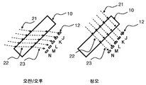
- FIG. 8 is a layout view of a solar focal position and a solar energy absorbing plate transmitted, refracted, and focused through a columnar light collecting device installed on the ground;
- the solar position tracking device regardless of the position of the sun in the day or with or without sunlight, the solar position tracking device and the column condensing device to easily track the position of the sun without moving
- a solar position tracking device having a solar energy absorbing device and an energy amount measuring device will be described in detail with reference to the drawings.
- the columnar concentrator 10 of the present invention has a characteristic of having the same transmission, refraction, and condensation, regardless of the angle at which the sunlight is incident in a circular, elliptical, or partial circular cross section. Otherwise, the sun does not need to be tracked and moved, and as shown in FIG. 1, a focal trajectory is made at a position separated by a focal length of the rear of the column concentrator according to the movement of the sun from sunrise to sunset.
- the plurality of solar energy absorbing plates 11 having the same width and the same plate shape are continuously disposed in the circumferential direction at the position of the solar focal trajectory from the sunrise angle to the sunset angle so that each absorbing plate absorbs sunlight.
- the projection area where the absorber plate is in contact with the sun is the same as the top view (above) of FIG.
- the amount of energy absorbed in each absorbing plate has a characteristic related to the projected area of the absorbing plate.
- the absorbing plate receiving the sunlight out of the light collecting device has a unique characteristic value, and the absorbing plates B, C, D that the solar focal point has a significantly high amount of energy see.
- the amount of energy absorbed by each absorber is explained in the enlarged view of FIG. 4.
- the solar focal width is about 2 absorbers wide and spans absorbers B, C, and D, the amount of energy measured by each absorber is measured.
- the amount of absorption of solar energy of absorber B changes according to the position of the sun. This phenomenon occurs sequentially in all absorbers, and the position of the sun is due to the change in energy of absorbers that compares and focuses the energy of each absorber. You can check.
- the width of the solar energy absorbing plate is determined according to the physical characteristics such as the diameter, refractive index, and focal width of the light collecting device. For example, when the diameter of the column concentrator is 30 cm and the focal orbit diameter is 50 cm, 80 absorbent plates having a width of 0.9 cm may be disposed on the focal orbit in a semicircle of about 180 degrees with an interval of 0.1 cm. One absorber plate corresponds to about 9 minutes. If necessary, the absorption plates can be arranged in multiple lines to further refine the time interval.
- Each absorber plate is connected to a device for measuring the amount of energy absorbed to calculate the change or rate of change of energy from the amount of energy in each absorber plate, and to determine the position of the sun by comparing the difference in the amount of energy between the absorber plates. In any case, the sun exists over the condenser of the absorber plates with the highest energy levels.
- the energy amount measuring device is a device for measuring the amount of solar energy absorbed by each solar energy absorbing plate by the amount of electrical energy or thermal energy. When the solar cell is used as an absorption plate, solar energy is absorbed by each absorption plate to generate electric current or electric power in the absorption plate, and the energy amount measuring device measures electric current or electric power generated by the absorption plate.
- the energy amount measuring device measures the temperature of the absorption plate It is a device for measuring the amount of thermal energy.
- each absorbing plate has a different diameter but has the same center as that of the light collecting device. The distance of each absorbing plate from the center of the light collecting device is slightly spaced apart to give a difference in the concentration of sunlight. Each absorber is connected to an energy measuring device to determine the degree of absorption of sunlight.
- FIG. 6 shows a cross section according to the angle of sunlight incident on the column concentrator, and the focal length of the sunlight passing through these cross sections is different.
- the solar focal length 31 from the concentrator center is the longest when vertical as shown in FIG.
- FIG. 8 is a view illustrating the principle of the solar position tracking device of the present invention installed on the ground and operating at am / pm and noon, and the sunlight passing through the condenser in diagonal lines due to the low altitude of the sun in the morning and afternoon is absorbed into the absorber plate K.
- the amount of energy absorbed by each absorbing plate is in the order of absorbing plate K> absorbing plate J> absorbing plate L> absorbing plate M> absorbing plate N in the morning.
- the angle of incidence of sunlight becomes larger and the focal length becomes longer, focusing on the absorber M at noon, and the largest amount of energy is measured.
- it is absorber M> absorber L> absorber N> absorber K> absorber J.
- the afternoon go back. Comparing the amount of energy and the ratio of the amount of energy of each absorber plate, the angle of incidence of sunlight can be identified, so the position of the sun can be accurately tracked.
Landscapes
- Physics & Mathematics (AREA)
- Engineering & Computer Science (AREA)
- Life Sciences & Earth Sciences (AREA)
- Sustainable Development (AREA)
- Electromagnetism (AREA)
- General Physics & Mathematics (AREA)
- Radar, Positioning & Navigation (AREA)
- Remote Sensing (AREA)
- Sustainable Energy (AREA)
- Thermal Sciences (AREA)
- Chemical & Material Sciences (AREA)
- Combustion & Propulsion (AREA)
- Mechanical Engineering (AREA)
- General Engineering & Computer Science (AREA)
- Photovoltaic Devices (AREA)
- Control Of Position Or Direction (AREA)
Abstract
Description
Claims (7)
- 길이(축) 방향으로 긴 속이 채워진 봉(기둥) 형태이며, 전면부로 입사하는 태양광을 투과, 굴절 및 집중시켜 봉의 후면부에서 초점거리만큼 떨어진 위치에 초점을 맺게 하는 기둥형 집광장치와;기둥형 집광장치의 물리적 지름보다 작은 폭을 가지며 동일한 크기와 형태를 가지는 다수의 태양에너지 흡수판을 태양의 이동에 따라 기둥형 집광장치의 후면부에 생기는 초점 궤도상에 기둥형 집광장치와 중심이 같으며 원주 방향으로 연속 배치한 태양 에너지 흡수 장치와;각각의 태양에너지 흡수판에 흡수된 에너지의 양을 측정하는 에너지량 측정 장치를 포함한 태양 위치 추적 장치
- 길이(축) 방향으로 긴 속이 채워진 봉(기둥) 형태이며, 전면부로 입사하는 태양광을 투과, 굴절 및 집중시켜 봉의 후면부에서 초점거리만큼 떨어진 위치에 초점을 맺게 하는 기둥형 집광장치와;반원형 띠 형태이며 지름이 다른 다수의 태양에너지 흡수판을 기둥형 집광장치의 후면부에 생기는 초점 위치 부근에 기둥형 집광장치와 중심이 같게 하여 기둥의 길이 방향으로 연속 배치한 태양 에너지 흡수 장치와;각각의 태양에너지 흡수판에 흡수된 에너지의 양을 측정하는 에너지량 측정 장치를 포함한 태양 위치 추적 장치
- 제1항과 제2항에 있어서 기둥형 집광장치는 태양광이 입사되는 방향의 반대편에 초점을 맺게 하는 것으로 원형 또는 타원형 또는 부분원형의 단면을 가진 집광장치를 포함한 태양 위치 추적 장치
- 제1항과 제2항에 있어서 기둥형 집광장치는 내부로 물과 같은 액체 물질을 흐르게 하여 태양광의 일부를 흡수하여 태양에너지 흡수판의 온도를 조절할 수 있는 파이프 형태의 집광장치를 포함한 태양 위치 추적 장치
- 제1항과 제2항에 있어서 기둥형 집광장치는 초점 길이를 조정할 수 있도록 집광장치의 내부와 외부가 다른 굴절률을 가지는 재질로 구성한 집광장치를 포함한 태양 위치 추적 장치
- 제1항과 제2항에 있어서 태양에너지 흡수 장치는 태양전지셀로 구성되며 에너지량 측정 장치는 태양전지셀로부터 발생하는 전기 에너지량을 측정하는 장치를 포함한 태양 위치 추적 장치
- 제1항과 제2항에 있어서 에너지량 측정 장치는 태양에너지 흡수 장치에 흡수된 열에너지를 측정하는 장치를 포함한 태양 위치 추적 장치
Priority Applications (2)
| Application Number | Priority Date | Filing Date | Title |
|---|---|---|---|
| JP2013514107A JP2013529769A (ja) | 2010-06-10 | 2011-06-03 | 円筒状集光装置が具備された太陽位置追跡装置 |
| US13/703,132 US20130074824A1 (en) | 2010-06-10 | 2011-06-03 | Solar position tracking apparatus comprising a cylindrical light focusing device |
Applications Claiming Priority (2)
| Application Number | Priority Date | Filing Date | Title |
|---|---|---|---|
| KR10-2010-0054675 | 2010-06-10 | ||
| KR1020100054675A KR101042940B1 (ko) | 2010-06-10 | 2010-06-10 | 기둥형 집광장치를 구비한 태양 위치 추적 장치 |
Publications (2)
| Publication Number | Publication Date |
|---|---|
| WO2011155729A2 true WO2011155729A2 (ko) | 2011-12-15 |
| WO2011155729A3 WO2011155729A3 (ko) | 2012-04-26 |
Family
ID=42369376
Family Applications (1)
| Application Number | Title | Priority Date | Filing Date |
|---|---|---|---|
| PCT/KR2011/004068 Ceased WO2011155729A2 (ko) | 2010-06-10 | 2011-06-03 | 기둥형 집광장치를 구비한 태양 위치 추적 장치 |
Country Status (4)
| Country | Link |
|---|---|
| US (1) | US20130074824A1 (ko) |
| JP (1) | JP2013529769A (ko) |
| KR (1) | KR101042940B1 (ko) |
| WO (1) | WO2011155729A2 (ko) |
Families Citing this family (3)
| Publication number | Priority date | Publication date | Assignee | Title |
|---|---|---|---|---|
| US9134458B2 (en) | 2013-06-25 | 2015-09-15 | General Electric Company | Prediction of solar obscuration events based on detection of spectral distribution shifts caused by approaching clouds |
| KR101954245B1 (ko) * | 2017-06-14 | 2019-03-05 | 명지대학교 산학협력단 | 일별 태양추적이 필요없는 집광형 태양전지모듈 |
| KR102260654B1 (ko) * | 2019-03-04 | 2021-06-07 | 전남대학교산학협력단 | 집광형 태양전지 발전용 고정식 태양광 집광장치 |
Family Cites Families (10)
| Publication number | Priority date | Publication date | Assignee | Title |
|---|---|---|---|---|
| US4058110A (en) | 1975-08-05 | 1977-11-15 | Holt F Sheppard | Wide angle solar heat collection system |
| JP3558968B2 (ja) * | 2000-06-30 | 2004-08-25 | 株式会社エヌ・ティ・ティ ファシリティーズ | 太陽光発電装置 |
| WO2005071760A1 (en) * | 2004-01-23 | 2005-08-04 | Origin Energy Solar Pty Ltd | Solar panel |
| KR20060013621A (ko) * | 2004-08-07 | 2006-02-13 | 김종수 | 원통렌즈(cylinder lens)를 이용한 태양열 획득방법 |
| KR100696326B1 (ko) | 2005-11-22 | 2007-03-20 | 주식회사 휠코리아 | 태양 추적장치 및 그를 이용한 집광 시스템 |
| KR100799094B1 (ko) | 2006-05-24 | 2008-01-29 | 제주대학교 산학협력단 | 태양에너지 집열 및 발전 시스템용 태양광 추적 장치 |
| WO2009008996A2 (en) * | 2007-07-06 | 2009-01-15 | Rensselaer Polytechnic Institute | Design and fabrication of a local concentrator system |
| US7698825B2 (en) | 2007-08-17 | 2010-04-20 | The Trustees Of Columbia University In The City Of New York | Automatic solar compass |
| JP2009270803A (ja) * | 2008-05-01 | 2009-11-19 | Yamada Kiyohiko | 水を利用した太陽光集光レンズによる蓄熱装置 |
| US9423533B2 (en) * | 2010-04-26 | 2016-08-23 | Guardian Industries Corp. | Patterned glass cylindrical lens arrays for concentrated photovoltaic systems, and/or methods of making the same |
-
2010
- 2010-06-10 KR KR1020100054675A patent/KR101042940B1/ko not_active Expired - Fee Related
-
2011
- 2011-06-03 JP JP2013514107A patent/JP2013529769A/ja not_active Withdrawn
- 2011-06-03 WO PCT/KR2011/004068 patent/WO2011155729A2/ko not_active Ceased
- 2011-06-03 US US13/703,132 patent/US20130074824A1/en not_active Abandoned
Also Published As
| Publication number | Publication date |
|---|---|
| US20130074824A1 (en) | 2013-03-28 |
| KR101042940B1 (ko) | 2011-06-24 |
| KR20100072157A (ko) | 2010-06-30 |
| JP2013529769A (ja) | 2013-07-22 |
| WO2011155729A3 (ko) | 2012-04-26 |
Similar Documents
| Publication | Publication Date | Title |
|---|---|---|
| JP5876873B2 (ja) | 柱状集光装置が具備された太陽光発電装置 | |
| Zheng et al. | Design and experimental analysis of a cylindrical compound Fresnel solar concentrator | |
| JPH09246585A (ja) | 追尾型太陽電池装置 | |
| CN102374477A (zh) | 一种阳光智能入户系统 | |
| CN106915790B (zh) | 一种充液式柔性聚光水下太阳能海水淡化装置 | |
| KR101042940B1 (ko) | 기둥형 집광장치를 구비한 태양 위치 추적 장치 | |
| US9255981B2 (en) | Sunlight collection device and method for tracking sunlight | |
| KR101093773B1 (ko) | 태양광 집광장치 | |
| CN101280967A (zh) | 免跟踪球透镜阵列集热系统 | |
| WO2018113631A1 (zh) | 一种太阳能聚光装置及使用该装置的建筑物或构筑物结构 | |
| CN204065838U (zh) | 牵拉式太阳能聚光跟踪装置 | |
| CN203054614U (zh) | 一种太阳能线性聚集装置 | |
| US8623180B2 (en) | Seawater desalinization system | |
| CN201166475Y (zh) | 平面透射式线聚焦太阳能聚光集热器 | |
| KR200353337Y1 (ko) | 볼록렌즈를 이용한 태양열 집열장치 | |
| WO2022169000A1 (ko) | 온도센서를 이용하여 태양광을 추적할 수 있는 ptc형 태양열 시스템 | |
| CN100368831C (zh) | 一种采聚太阳能的掩模片及采用掩模片的太阳能装置 | |
| TWI580911B (zh) | 線性聚焦之單軸追日裝置 | |
| WO2014106478A1 (zh) | 一种太阳能线性聚集装置及系统控制方法 | |
| RU95079U1 (ru) | Солнечный нагреватель | |
| KR20130059197A (ko) | 태양광 추적 장치 및 방법 그리고 이것을 적용한 에너지 수집 장치 및 그 운영 방법 | |
| JPS6237744B2 (ko) | ||
| CN111841051A (zh) | 一种菲涅尔型多倍聚光效果的蒸馏装置 | |
| EP2148150A2 (en) | Device for collecting and concentrating solar energy and transmitting it to a heat carrier fluid | |
| JPS5926220B2 (ja) | 多重放熱防御相乗加熱太陽熱コレクタ |
Legal Events
| Date | Code | Title | Description |
|---|---|---|---|
| 121 | Ep: the epo has been informed by wipo that ep was designated in this application |
Ref document number: 11792640 Country of ref document: EP Kind code of ref document: A2 |
|
| ENP | Entry into the national phase |
Ref document number: 2013514107 Country of ref document: JP Kind code of ref document: A |
|
| NENP | Non-entry into the national phase |
Ref country code: DE |
|
| WWE | Wipo information: entry into national phase |
Ref document number: 13703132 Country of ref document: US |
|
| 122 | Ep: pct application non-entry in european phase |
Ref document number: 11792640 Country of ref document: EP Kind code of ref document: A2 |