WO2011161978A1 - 注入材、注入材の製造方法及び注入工法 - Google Patents
注入材、注入材の製造方法及び注入工法 Download PDFInfo
- Publication number
- WO2011161978A1 WO2011161978A1 PCT/JP2011/052577 JP2011052577W WO2011161978A1 WO 2011161978 A1 WO2011161978 A1 WO 2011161978A1 JP 2011052577 W JP2011052577 W JP 2011052577W WO 2011161978 A1 WO2011161978 A1 WO 2011161978A1
- Authority
- WO
- WIPO (PCT)
- Prior art keywords
- water
- particle size
- injection
- dispersant
- silica
- Prior art date
- Legal status (The legal status is an assumption and is not a legal conclusion. Google has not performed a legal analysis and makes no representation as to the accuracy of the status listed.)
- Ceased
Links
Classifications
-
- E—FIXED CONSTRUCTIONS
- E02—HYDRAULIC ENGINEERING; FOUNDATIONS; SOIL SHIFTING
- E02D—FOUNDATIONS; EXCAVATIONS; EMBANKMENTS; UNDERGROUND OR UNDERWATER STRUCTURES
- E02D3/00—Improving or preserving soil or rock, e.g. preserving permafrost soil
- E02D3/12—Consolidating by placing solidifying or pore-filling substances in the soil
-
- C—CHEMISTRY; METALLURGY
- C01—INORGANIC CHEMISTRY
- C01B—NON-METALLIC ELEMENTS; COMPOUNDS THEREOF; METALLOIDS OR COMPOUNDS THEREOF NOT COVERED BY SUBCLASS C01C
- C01B33/00—Silicon; Compounds thereof
- C01B33/113—Silicon oxides; Hydrates thereof
- C01B33/12—Silica; Hydrates thereof, e.g. lepidoic silicic acid
- C01B33/18—Preparation of finely divided silica neither in sol nor in gel form; After-treatment thereof
-
- C—CHEMISTRY; METALLURGY
- C04—CEMENTS; CONCRETE; ARTIFICIAL STONE; CERAMICS; REFRACTORIES
- C04B—LIME, MAGNESIA; SLAG; CEMENTS; COMPOSITIONS THEREOF, e.g. MORTARS, CONCRETE OR LIKE BUILDING MATERIALS; ARTIFICIAL STONE; CERAMICS; REFRACTORIES; TREATMENT OF NATURAL STONE
- C04B28/00—Compositions of mortars, concrete or artificial stone, containing inorganic binders or the reaction product of an inorganic and an organic binder, e.g. polycarboxylate cements
- C04B28/02—Compositions of mortars, concrete or artificial stone, containing inorganic binders or the reaction product of an inorganic and an organic binder, e.g. polycarboxylate cements containing hydraulic cements other than calcium sulfates
- C04B28/10—Lime cements or magnesium oxide cements
- C04B28/12—Hydraulic lime
-
- C—CHEMISTRY; METALLURGY
- C04—CEMENTS; CONCRETE; ARTIFICIAL STONE; CERAMICS; REFRACTORIES
- C04B—LIME, MAGNESIA; SLAG; CEMENTS; COMPOSITIONS THEREOF, e.g. MORTARS, CONCRETE OR LIKE BUILDING MATERIALS; ARTIFICIAL STONE; CERAMICS; REFRACTORIES; TREATMENT OF NATURAL STONE
- C04B40/00—Processes, in general, for influencing or modifying the properties of mortars, concrete or artificial stone compositions, e.g. their setting or hardening ability
- C04B40/0028—Aspects relating to the mixing step of the mortar preparation
- C04B40/0039—Premixtures of ingredients
-
- C—CHEMISTRY; METALLURGY
- C04—CEMENTS; CONCRETE; ARTIFICIAL STONE; CERAMICS; REFRACTORIES
- C04B—LIME, MAGNESIA; SLAG; CEMENTS; COMPOSITIONS THEREOF, e.g. MORTARS, CONCRETE OR LIKE BUILDING MATERIALS; ARTIFICIAL STONE; CERAMICS; REFRACTORIES; TREATMENT OF NATURAL STONE
- C04B40/00—Processes, in general, for influencing or modifying the properties of mortars, concrete or artificial stone compositions, e.g. their setting or hardening ability
- C04B40/06—Inhibiting the setting, e.g. mortars of the deferred action type containing water in breakable containers ; Inhibiting the action of active ingredients
- C04B40/0641—Mechanical separation of ingredients, e.g. accelerator in breakable microcapsules
- C04B40/065—Two or more component mortars
-
- C—CHEMISTRY; METALLURGY
- C09—DYES; PAINTS; POLISHES; NATURAL RESINS; ADHESIVES; COMPOSITIONS NOT OTHERWISE PROVIDED FOR; APPLICATIONS OF MATERIALS NOT OTHERWISE PROVIDED FOR
- C09K—MATERIALS FOR MISCELLANEOUS APPLICATIONS, NOT PROVIDED FOR ELSEWHERE
- C09K17/00—Soil-conditioning materials or soil-stabilising materials
- C09K17/40—Soil-conditioning materials or soil-stabilising materials containing mixtures of inorganic and organic compounds
-
- C—CHEMISTRY; METALLURGY
- C04—CEMENTS; CONCRETE; ARTIFICIAL STONE; CERAMICS; REFRACTORIES
- C04B—LIME, MAGNESIA; SLAG; CEMENTS; COMPOSITIONS THEREOF, e.g. MORTARS, CONCRETE OR LIKE BUILDING MATERIALS; ARTIFICIAL STONE; CERAMICS; REFRACTORIES; TREATMENT OF NATURAL STONE
- C04B2111/00—Mortars, concrete or artificial stone or mixtures to prepare them, characterised by specific function, property or use
- C04B2111/00474—Uses not provided for elsewhere in C04B2111/00
- C04B2111/00724—Uses not provided for elsewhere in C04B2111/00 in mining operations, e.g. for backfilling; in making tunnels or galleries
-
- C—CHEMISTRY; METALLURGY
- C04—CEMENTS; CONCRETE; ARTIFICIAL STONE; CERAMICS; REFRACTORIES
- C04B—LIME, MAGNESIA; SLAG; CEMENTS; COMPOSITIONS THEREOF, e.g. MORTARS, CONCRETE OR LIKE BUILDING MATERIALS; ARTIFICIAL STONE; CERAMICS; REFRACTORIES; TREATMENT OF NATURAL STONE
- C04B2111/00—Mortars, concrete or artificial stone or mixtures to prepare them, characterised by specific function, property or use
- C04B2111/70—Grouts, e.g. injection mixtures for cables for prestressed concrete
-
- C—CHEMISTRY; METALLURGY
- C04—CEMENTS; CONCRETE; ARTIFICIAL STONE; CERAMICS; REFRACTORIES
- C04B—LIME, MAGNESIA; SLAG; CEMENTS; COMPOSITIONS THEREOF, e.g. MORTARS, CONCRETE OR LIKE BUILDING MATERIALS; ARTIFICIAL STONE; CERAMICS; REFRACTORIES; TREATMENT OF NATURAL STONE
- C04B2111/00—Mortars, concrete or artificial stone or mixtures to prepare them, characterised by specific function, property or use
- C04B2111/74—Underwater applications
-
- Y—GENERAL TAGGING OF NEW TECHNOLOGICAL DEVELOPMENTS; GENERAL TAGGING OF CROSS-SECTIONAL TECHNOLOGIES SPANNING OVER SEVERAL SECTIONS OF THE IPC; TECHNICAL SUBJECTS COVERED BY FORMER USPC CROSS-REFERENCE ART COLLECTIONS [XRACs] AND DIGESTS
- Y02—TECHNOLOGIES OR APPLICATIONS FOR MITIGATION OR ADAPTATION AGAINST CLIMATE CHANGE
- Y02W—CLIMATE CHANGE MITIGATION TECHNOLOGIES RELATED TO WASTEWATER TREATMENT OR WASTE MANAGEMENT
- Y02W30/00—Technologies for solid waste management
- Y02W30/50—Reuse, recycling or recovery technologies
- Y02W30/91—Use of waste materials as fillers for mortars or concrete
Definitions
- the present invention relates to an injection material and an injection method.
- the present invention relates to an injection material having excellent permeability, water-stopping property, and high durability even under high water pressure, a method for producing the injection material, and a ground injection method.
- a high-permeability injection material generally called a solution-type injection material, water glass, silica sol, or an injection material mainly composed of active silica obtained by treating water glass with a cation exchange resin or an ion exchange membrane
- a silica colloid injection material stabilized by weakly alkaline having a pH of 9 to 10 by concentrating and increasing the active silica has been used (Patent Documents 1 and 2).
- the above-mentioned solution-type injection material has a low strength (referred to as homogel strength), and thus is pushed out by water pressure and has poor durability. Therefore, fine particle cement, which is a suspension-type injection material, has been studied, but the average particle size is as large as about 5 ⁇ m and does not penetrate into fine cracks. is there.
- Patent Document 3 injects an injection material mainly composed of fine-particle silica into the ground, and there is no description about using a suspension containing a calcium compound.
- Patent Document 4 describes silica, lime, and a dispersant, but does not describe that a dispersant is contained in each of a suspension containing silica and a suspension containing lime.
- Patent Document 5 states that “the addition of water and a dispersant to a powdered ultrafine particle material, pulverizing and stirring the ultrafine particle material, further adding a dispersant, pulverizing and stirring the ultrafine particle material.
- a dispersant is added, and the ultrafine particle material is crushed and mixed with the second highly dispersed low viscosity ultrafine particle slurry, and the ultrafine particle material is crushed and stirred.
- the average particle size when measured using a laser diffraction / scattering particle size analyzer is not clear.
- fine silica powders other than silica fume as the ultrafine particle material, and there is no description about durability when a highly dispersed low viscosity ultrafine particle slurry is used as an injection material.
- Patent Documents 6 and 7 a slurry in which metal silicon powder is dispersed in water and has a metal silicon powder concentration of 20 to 70%, or 5 to 60%, is contained in a flame at least 10 m / second or at least 20 m.
- a fine silica powder fine spherical silica
- a method of injecting, burning, and oxidizing at a protruding speed of at least / sec is shown, the use of this fine spherical silica as an injection material is not shown.
- Patent Document 8 states that “a method of applying an injection material in which a material A previously containing a pozzolanic substance and water and a material B previously containing a calcium-containing material and water are separately injected” (Claim 1), “ The invention of claim 1 in which the A material contains a dispersant in advance. (Claim 2) describes the invention, "In addition, in order to improve dispersibility, a dispersant may be used in combination with the B material. (Paragraph [0014]), but there is no specific description of using a dispersant in combination with a calcium-containing substance and water-containing B material. In the case of simultaneous injection, there was a problem that the injection material hardened immediately and injection was impossible (paragraph [0022]).
- silica obtained by melting a raw material silica stone having an average particle size of 1 ⁇ m or less into a spherical shape by melting it in a high-temperature flame is used. It is not shown that the average particle size of silica is 1 ⁇ m or less. Neither is it shown that the calcium-containing material is ground and dispersed to 1 ⁇ m or less.
- Non-Patent Document 1 describes a grout material (injection material) composed of a mixture of agent A containing ultrafine spherical silica and water and agent B containing ultrafine calcium hydroxide, a dispersant and water.
- agent A containing ultrafine spherical silica and water
- agent B containing ultrafine calcium hydroxide, a dispersant and water.
- the particle sizes of the ultrafine spherical silica and the ultrafine calcium hydroxide are each approximately 1 ⁇ m or less.
- JISJR 1629 it is Since the sonic dispersion treatment is performed, the average particle diameter when the particle size distribution is measured without performing the ultrasonic dispersion treatment is not clear.
- an object of the present invention is to provide an injection material and an injection method that have high permeability and have an excellent water stop effect and durability.
- the present invention employs the following means in order to solve the above problems.
- a material subjected to a wet dispersion treatment containing fine particle silica having a mean particle size of 1.0 ⁇ m or less measured using a laser diffraction particle size distribution meter without performing an ultrasonic dispersion treatment, a dispersant and water From a mixture of a calcium compound having an average particle size of 1.0 ⁇ m or less measured using a laser diffraction particle size distribution meter without performing ultrasonic dispersion treatment, a B material subjected to wet pulverization dispersion treatment containing a dispersant and water.
- An injection material wherein the fine particle silica is manufactured by a method in which a slurry in which metal silicon powder is dispersed in water is injected into a flame and burned and oxidized.
- the material A is a suspension subjected to a wet dispersion treatment containing fine particle silica having an average particle size of 1.0 ⁇ m or less and water measured using a laser diffraction particle size distribution meter without performing an ultrasonic dispersion treatment.
- the fine particle silica is the injection material according to any one of (1) and (1) to (3), which is fine particle spherical silica having an average value of sphericity of 95% or more.
- the material B was subjected to a wet pulverization dispersion treatment containing a calcium compound having an average particle size of 1.0 ⁇ m or less, a dispersant, and water measured using a laser diffraction particle size distribution meter without performing an ultrasonic dispersion treatment.
- the amount of the dispersant for the A material used is any one of (1) to (6), which is 0.1 to 30 parts by mass (in terms of solid content) with respect to 100 parts by mass of fine-particle silica. It is an injection material.
- a slurry in which metal silicon powder is dispersed in water is injected into a flame and burned, and water is added to fine particle silica produced by a method of oxidation, and wet dispersion treatment is performed using a pulverizer using high-pressure water,
- a suspension containing fine particle silica and water having an average particle size of 1.0 ⁇ m or less measured using a laser diffraction particle size distribution analyzer without ultrasonic dispersion treatment is used.
- a material is produced by mixing water according to the conditions, while dispersing and water are added to the calcium compound, and wet pulverization and dispersion treatment is performed using a pulverizer using high-pressure water to perform ultrasonic dispersion treatment.
- the suspension contains calcium compound, dispersant, and water whose average particle size is 1.0 ⁇ m or less, and this suspension is further mixed with water as necessary.
- a method for producing an injection material wherein the A material and the B material are mixed.
- the calcium compound is calcium hydroxide.
- Mixing and injecting wet pulverized and dispersed B material containing calcium compound having an average particle size of 1.0 ⁇ m or less measured using a laser diffraction particle size distribution meter without ultrasonic dispersion treatment, a dispersant and water An injection method characterized in that the fine particle silica is manufactured by a method in which a slurry in which metal silicon powder is dispersed in water is injected into a flame and burned and oxidized.
- the material A is a suspension subjected to a wet dispersion treatment containing fine particle silica having an average particle diameter of 1.0 ⁇ m or less and water measured using a laser diffraction particle size distribution meter without performing an ultrasonic dispersion treatment.
- Suspension subjected to a wet dispersion treatment in which the material A contains fine particle silica having an average particle diameter of 1.0 ⁇ m or less and water measured using a laser diffraction particle size distribution meter without performing an ultrasonic dispersion treatment The injection method according to (14) above, wherein a liquid and a dispersant and water are mixed.
- part and% used by this invention mean a mass part and mass%.
- fine silica particles produced by a method in which a slurry in which metal silicon powder is dispersed in water are injected into a flame and burned and oxidized are used.
- This fine particle spherical silica is preferable in that it has little aggregation (structure) and high permeability.
- the particle size of the fine particle silica is set to an average particle size of 1.0 ⁇ m or less in order to improve the permeability and compressive strength characteristics, but is preferably 0.05 to 1.0 ⁇ m, preferably 0.05 to 0.00. 6 ⁇ m is more preferable.
- fine particle spherical silica powder having an average particle diameter excellent in fluidity promoting effect can be collected by the classification treatment. For example, it can manufacture by the method of patent document 6 or patent document 7.
- fine particle silica has an average value of sphericity of preferably 90% or more, more preferably 95% or more, and particularly preferably 97% or more in terms of permeability and compressive strength characteristics.
- the sphericity can be measured using a scanning electron microscope (“JSM-T200 type” manufactured by JEOL Ltd.) and an image analyzer (manufactured by Nippon Avionics Co., Ltd.). For example, first, the projected area (A) and the perimeter (PM) of particles are measured from an SEM photograph of powder. When the area of a perfect circle corresponding to the perimeter (PM) is (B), the sphericity of the particle can be displayed as A / B ⁇ 100 (%).
- JSM-T200 type manufactured by JEOL Ltd.
- an image analyzer manufactured by Nippon Avionics Co., Ltd.
- the amorphous ratio of the fine particle silica is preferably 95% or more, more preferably 98% or more, and particularly preferably 100%.
- the amorphous ratio is determined by X-ray diffraction analysis of the sample using a powder X-ray diffractometer (for example, “Mini Flex” manufactured by RIGAKU) in the range of 2 ⁇ of CuK ⁇ ray of 26 to 27.5 °. It can be measured from the intensity ratio of the peaks.
- powder X-ray diffractometer for example, “Mini Flex” manufactured by RIGAKU
- fine-particle silica include trade names “SFP-20M” and “SFP-30M” manufactured by Denki Kagaku Kogyo Co., Ltd. and trade names “Admafine” manufactured by Admatechs.
- Examples of the calcium compound of the present invention include inorganic substances such as calcium hydroxide, calcium chloride and gypsum, and calcium salts of organic acids such as calcium formate.
- inorganic substances such as calcium hydroxide, calcium chloride and gypsum
- calcium salts of organic acids such as calcium formate.
- calcium hydroxide is preferable in terms of compressive strength.
- the calcium compound is pulverized to an average particle size of 1.0 ⁇ m or less in order to improve the permeability and compressive strength characteristics, but is preferably pulverized to an average particle size of 0.05 to 1.0 ⁇ m. It is more preferable to grind to 0.05 to 0.5 ⁇ m.
- the fine particle silica and the calcium compound are each dispersed in water to produce the A material and the B material, respectively.
- the concentration of fine particle silica in the A material of the present invention is preferably 80% or less, more preferably 5 to 60%, and most preferably 10 to 40%.
- concentration of the fine particle silica exceeds 80%, the viscosity becomes high and the permeability may be lowered.
- this invention it is also possible to manufacture a high concentration fine particle silica slurry beforehand, and to dilute with water at the time of construction. When it does not penetrate at a high concentration, it can be injected reliably into a small crack by continuing the injection for a long time at a low concentration of 5% or less, and a high improvement effect can be obtained.
- the amount of the calcium compound in the B material of the present invention is preferably 20 to 250 parts, more preferably 50 to 200 parts with respect to 100 parts of fine particle silica. If the amount of the calcium compound is less than 20 parts, the compressive strength may be reduced, and if it exceeds 250 parts, the permeability may be reduced.
- the concentration of the calcium compound in the B material of the present invention is preferably 50% or less, more preferably 2 to 40%, and most preferably 5 to 30%.
- concentration of the calcium compound exceeds 50%, the viscosity may become high and the permeability may be lowered.
- the amount of dispersant used can be reduced to an extremely small amount to shorten the gel time or make it instantaneous, which can be used for leak prevention or limited injection.
- naphthalene sulfonic acid type naphthalene sulfonic acid type, lignin sulfonic acid type, melamine sulfonic acid type, polycarboxylic acid type, and polyether type dispersants can be used.
- a sulfonic acid-based dispersant and / or a polycarboxylic acid-based dispersant are preferable in terms of permeability and compressive strength characteristics.
- the amount of the dispersant for the A material used is preferably 0.1 to 30 parts (in terms of solid content) and more preferably 5 to 20 parts (in terms of solid content) with respect to 100 parts of the fine particle silica of the A material. If it is less than 0.1 part, it will solidify at the moment of mixing with the other liquid, and the permeability to the ground may be poor, and if it exceeds 30 parts, the compression strength may be low. Fine particle silica produced by injecting a slurry of metal silicon powder in water into a flame, burning, and oxidizing it has good dispersibility and can be dispersed in water without first adding a dispersant. Therefore, a dispersant may be added later. This water dispersibility is presumed to be related to the silanol group concentration.
- the amount of the dispersant for the material B used is preferably 1 to 30 parts (in terms of solid content), more preferably 5 to 20 parts (in terms of solid content) with respect to 100 parts of the calcium compound. If it is less than 1 part, it reacts and solidifies at the moment of mixing with the other liquid, and the permeability to the ground may be poor, and if it exceeds 30 parts, the compression strength may be low.
- the injection material of the present invention can contain a curing time adjusting agent in order to adjust the curing time.
- the curing time adjusting agent is not particularly limited, but examples thereof include known inorganic salts such as alkali metal sulfates, alkali metal carbonates, alkali metal bicarbonates, alkali metal phosphates, gluconic acid, tartaric acid, citric acid.
- One or two or more types selected from organic acids such as acid, malic acid and lactic acid, salts of the organic acids, and the like can be mentioned.
- alkali metal sulfates and / or alkali metal carbonates are preferable from the viewpoint of compressive strength, and alkali metal sulfates are more preferable.
- Examples of the alkali metal sulfate include sodium sulfate and potassium sulfate.
- the amount of the curing time adjuster used is preferably 30 parts or less, more preferably 0.1 to 30 parts, and most preferably 1 to 10 parts with respect to 100 parts of the fine particle silica of material A. If the curing time adjusting agent exceeds 30 parts, the permeability may be poor.
- the mixing ratio of the A material and the B material is preferably 5: 1 to 1: 5, more preferably 2: 1 to 1: 2.
- the fine particle silica and calcium compound are preferably dispersed or pulverized by various wet pulverizers to reduce the average particle size.
- the average particle size referred to here is an ultrasonic wave obtained by subjecting a suspension subjected to a wet dispersion treatment to a normal pretreatment using a laser diffraction particle size distribution analyzer (for example, “LA-920 type” manufactured by HORIBA, Ltd.). It is a value measured in a water medium without performing a dispersion treatment. In JIS R 1629, since the particle size is measured after ultrasonically applying the agglomerate, the permeability may be poor even if it is actually injected into the ground.
- the suspension subjected to the wet dispersion treatment refers to the A material obtained by wet dispersion treatment of the fine particle silica and the B material obtained by dispersing the calcium compound together with wet grinding (referred to as “wet grinding dispersion treatment” in this specification).
- the wet pulverizer used in the present invention may be a method using any one of a high-speed stirrer, a medium stirring mill, a pulverizer using high-pressure water, etc., and is selected alone or in combination, and has a pulverization efficiency. From a high point, a pulverizer using high-pressure water is preferable.
- the high-speed stirrer a structure in which not only the stirrer simply rotates at a high speed but also a so-called turbulent state and a shearing force acts on the particles is preferable.
- trade names “Sharp Flow Mill” manufactured by Taiheiyo Kiko Co., Ltd. trade names “Homomixer”, “Homomic Line Mill”, “Homo Disper” manufactured by Tokushu Kika Kogyo Co., Ltd., and the like.
- a pulverizer using high-pressure water applies a high pressure of 50 to 400 MPa to the slurry, divides the slurry into two flow paths, and pulverizes them by colliding against each other at a portion where they merge again.
- pulverizer examples include “Starburst” and “Ultimizer” manufactured by Sugino Machine, “Nanomizer” manufactured by Nanomizer, and “Microfluidizer” manufactured by Microfluidics. Among these, “starburst” is preferable in terms of improving the permeability of the injection material into the ground.
- the injection method of the present invention is characterized by injecting the above injection material into the ground.
- the injection method of the present invention is excellent in, for example, filling of cracked rocks under high osmotic water pressure and water filling around a cavity formed by rock excavation, and filling of the injected material into the rock cracks, and Further, the present invention relates to an injection method capable of maintaining a long-term water-stopping property without pushing out the injection material even when a high osmotic water pressure acts, and the above-mentioned effects can be obtained.
- Example 1 100 parts of fine particle silica having different particle diameters and types, 10 parts of a dispersant, and 500 parts of water were mixed and subjected to a wet dispersion treatment with a product name “Starburst” manufactured by Sugino Machine Co., thereby producing A material (S1 to 7).
- a product name “Starburst” manufactured by Sugino Machine Co. 100 parts of commercially available calcium hydroxide (average particle size: 9.5 ⁇ m), 10 parts of a dispersant, and 500 parts of water are mixed, and wet grinding is performed using the same brand name “Starburst” manufactured by Sugino Machine.
- Dispersion treatment was performed to prepare a B material (C1 to 6). A material and B material were merged.
- a material and B material were mixed so that the usage-amount of a calcium compound might be 100 parts with respect to 100 parts of fine-particle silica.
- a permeability test and a compressive strength test were conducted. The formulation and results are shown in Table 1.
- the fine particle silica is produced by a method in which a metal silicon powder dispersed in water and having a metal silicon powder concentration of 30% is injected into a flame at a protruding speed of 2 to 150 m / sec, burned, oxidized, and melted into a spheroid. Manufactured.
- Fine particle silica S1 slurry having an average particle diameter of 0.05 ⁇ m after wet dispersion treatment, a sphericity of 97%, an amorphization rate of 100%, and a concentration of metal silicon powder in which metal silicon powder is dispersed in water is 30%
- Fine particle spherical silica fine particle silica S2 produced by a method of injecting, burning and oxidizing at a protruding speed of 150 m / second or more: average particle size 0.1 ⁇ m after wet dispersion treatment, sphericity 97%, amorphous ratio 100%
- Spherical silica fine particle silica S3 manufactured by a method in which a metal silicon powder dispersed in water and having a metal silicon powder concentration of 30% is injected into a flame at a protruding speed of 120 m / sec or more and burned and oxidized, wet dispersion A slurry having an average particle size of 0.6 ⁇ m after treatment,
- Fine particle spherical silica fine particle silica S4 manufactured by a method of injecting, burning, and oxidizing at a protrusion speed of 100 m / second or more: average particle size 1.0 ⁇ m after wet dispersion treatment, sphericity 96%, amorphous ratio 100%, Spherical silica fine particle silica S5 produced by a method in which a metal silicon powder dispersed in water and having a metal silicon powder concentration of 30% is injected into a flame at a protruding speed of 50 m / sec or more and burned and oxidized, wet dispersion An average particle size of 3.5 ⁇ m after treatment, a sphericity of 95%, an amorphous ratio of 100%, a metal silicon powder dispersed in water with a metal silicon powder concentration of 30% in a flame is a slurry of 2 m / second or more.
- Average particle diameter A laser diffraction particle size distribution meter (“LA-920 type” manufactured by Horiba, Ltd.) was used. The A material and the B material were measured in an aqueous medium without performing ultrasonic dispersion treatment. Penetration test: Using an injection device according to the JGS0831 standard of the Geotechnical Society, No. 8 silica sand was filled into a sample tank of 5 cm in diameter and 20 cm in length, and the penetration length of the injected material 30 minutes after the start of injection was defined as the penetration length. did.
- Compressive strength The cured product was taken out from the sample tank subjected to the permeability test, cut into a length of 100 mm, and the compressive strength was measured at 7 days and 28 days of age with an Amsler type compression tester. When the permeation length was 100 mm or less, the upper and lower surfaces of the cured body were finished and measured.
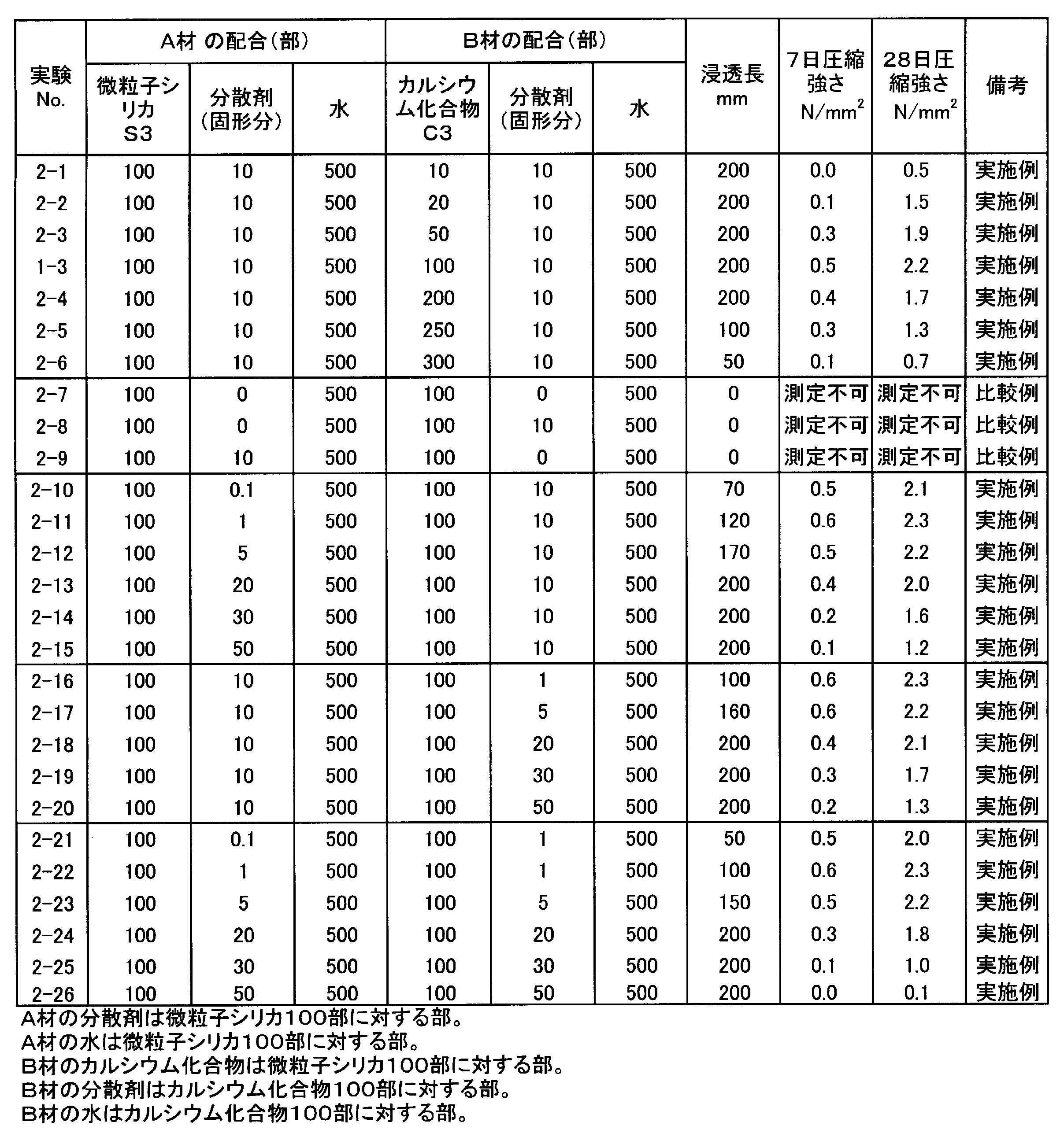
- Example 2 Example 1 except that the A material and the B material were mixed so that the amount of the calcium compound used was S3 and C3 subjected to the wet pulverization treatment, and the amount of the calcium compound was as shown in Table 2 with respect to 100 parts of the fine particle silica Similarly, a permeability test and a compressive strength test were performed. The formulation and results are shown in Table 2.
- Example 3 A material and a B material were used so that the amount of curing time adjusting agent shown in Table 3 per 100 parts of fine particle silica was used, and the amount of calcium compound used was as shown in Table 3 with respect to 100 parts of fine particle silica.
- a permeability test and a compressive strength test were conducted in the same manner as in Example 2 except that the mixture was mixed.
- citric acid which is an acidic curing time adjusting agent may react with calcium hydroxide, it was placed on the A material side, and a curing time adjusting agent other than citric acid was placed on the B material side.
- the formulation and results are shown in Table 3.
- Curing time adjusting agent T1 Sodium sulfate curing time adjusting agent
- T2 Potassium sulfate curing time adjusting agent
- T3 Sodium carbonate curing time adjusting agent
- T4 Citric acid
- Example 4 Particulate silica S3 (100 parts) and water (500 parts) were mixed and subjected to a wet dispersion treatment with a trade name “Starburst” manufactured by Sugino Machine Co., to produce a fine particle silica slurry.
- the fine particle silica slurry was mixed with 10 parts of a dispersant with respect to 100 parts of the fine particle silica to prepare A material.
- C3 of Example 1 was used for B material, and A material and B material were mixed so that the usage-amount of a calcium compound might be 100 parts with respect to 100 parts of fine particle silica.
- a permeability test and a compressive strength test were conducted. The formulation and results are shown in Table 4.
- the injection material of the present invention is a highly durable injection material that penetrates into fine cracks in rock, and exhibits excellent permeability and compressive strength characteristics.
- LPG underground It can be used for stockpiling, underground containment of radioactive waste, and water stoppage for dams and tunnels.
- the fine particle silica and calcium compound of the present invention are excellent in penetrability and compressive strength properties without performing ultrasonic dispersion treatment, and thus have a great economic effect.
Landscapes
- Chemical & Material Sciences (AREA)
- Engineering & Computer Science (AREA)
- Ceramic Engineering (AREA)
- Organic Chemistry (AREA)
- Structural Engineering (AREA)
- Materials Engineering (AREA)
- Life Sciences & Earth Sciences (AREA)
- Inorganic Chemistry (AREA)
- General Life Sciences & Earth Sciences (AREA)
- Soil Sciences (AREA)
- Agronomy & Crop Science (AREA)
- Environmental & Geological Engineering (AREA)
- Mining & Mineral Resources (AREA)
- Paleontology (AREA)
- Civil Engineering (AREA)
- General Engineering & Computer Science (AREA)
- Chemical Kinetics & Catalysis (AREA)
- Analytical Chemistry (AREA)
- Soil Conditioners And Soil-Stabilizing Materials (AREA)
- Consolidation Of Soil By Introduction Of Solidifying Substances Into Soil (AREA)
- Sealing Material Composition (AREA)
- Silicon Compounds (AREA)
Abstract
Description
また、特許文献4には、シリカ、ライム、分散剤の記載はあるが、シリカを含有する懸濁液、ライムを含有する懸濁液のそれぞれに分散剤を含有することの記載はない。
しかしながら、特許文献5に記載の発明は、平均粒径を1μm以下とするために、上記のように、超微粒子材料(シリカフュームおよび消石灰)の解砕、攪拌、分散剤の添加を繰り返し行うという複雑な工程を経なければならないという問題があり、また、一次粒子に近い高分散化低粘性超微粒子グラウトを作製するためには、解砕方式として、ボール(ビーズ)を媒体にしてスラリーをミキサーで撹拌するという方式を適用する必要があった(段落[0021])。そして、レーザー回折/散乱式粒度分析装置を用いて測定する場合には、通常はJIS R 1629に記載の通り、前処理として超音波分散処理を行うものであるから、超音波分散処理を行うことなくレーザー回折/散乱式粒度分析装置を用いて測定した場合の平均粒径は明らかではない。また、超微粒子材料として、シリカフューム以外の微細シリカ粉末についての記載はなく、高分散化低粘性超微粒子スラリーを注入材とした場合の耐久性についても記載されていない。
(1)超音波分散処理を行うことなくレーザー回折式粒度分布計を用いて測定した平均粒径が1.0μm以下である微粒子シリカ、分散剤及び水を含有する湿式分散処理したA材と、超音波分散処理を行うことなくレーザー回折式粒度分布計を用いて測定した平均粒径1.0μm以下のカルシウム化合物、分散剤及び水を含有する湿式粉砕分散処理したB材とを混合したものからなる注入材であって、前記微粒子シリカが金属シリコン粉末を水に分散させたスラリーを火炎中に噴射し燃焼、酸化させる方法で製造したものであることを特徴とする注入材である。
(2)前記A材が、超音波分散処理を行うことなくレーザー回折式粒度分布計を用いて測定した平均粒径が1.0μm以下である微粒子シリカ及び水を含有する湿式分散処理した懸濁液に、分散剤を混合したものである前記(1)の注入材である。
(3)前記A材が、超音波分散処理を行うことなくレーザー回折式粒度分布計を用いて測定した平均粒径が1.0μm以下である微粒子シリカ及び水を含有する湿式分散処理した懸濁液に、分散剤及び水を混合したものである前記(1)の注入材である。
(4)前記微粒子シリカは、球形度の平均値が95%以上の微粒子球状シリカである前記(1)前記(1)~(3)のうちのいずれかの注入材である。
(5)前記B材が、超音波分散処理を行うことなくレーザー回折式粒度分布計を用いて測定した平均粒径1.0μm以下のカルシウム化合物、分散剤及び水を含有する湿式粉砕分散処理した懸濁液に、さらに水を混合したものである前記(1)~(4)のうちのいずれかの注入材である。
(6)前記カルシウム化合物が、水酸化カルシウムである前記(1)~(5)のうちのいずれかの注入材である。
(7)前記A材の分散剤の使用量が、微粒子シリカ100質量部に対して0.1~30質量部(固形分換算)である前記(1)~(6)のうちのいずれかの注入材である。
(8)前記B材の分散剤の使用量が、カルシウム化合物100質量部に対して1~30質量部(固形分換算)である前記(1)~(7)のうちのいずれかの注入材である。
(9)さらに硬化時間調整剤を含有してなる前記(1)~(8)のうちのいずれかの注入材である。
(10)金属シリコン粉末を水に分散させたスラリーを火炎中に噴射し燃焼、酸化させる方法で製造した微粒子シリカに水を加え、高圧水を使用した粉砕機を用いて湿式分散処理して、超音波分散処理を行うことなくレーザー回折式粒度分布計を用いて測定した平均粒径が1.0μm以下である微粒子シリカ及び水を含有する懸濁液とし、この懸濁液に分散剤さらに必要に応じて水を混合してA材を製造し、一方、カルシウム化合物に分散剤及び水を加え、高圧水を使用した粉砕機を用いて湿式粉砕分散処理して、超音波分散処理を行うことなくレーザー回折式粒度分布計を用いて測定した平均粒径が1.0μm以下であるカルシウム化合物、分散剤及び水を含有する懸濁液とし、この懸濁液にさらに必要に応じて水を混合してB材を製造し、前記A材及び前記B材を混合することを特徴とする注入材の製造方法である。
(11)前記微粒子シリカは、球形度の平均値が95%以上の微粒子球状シリカである前記(10)の注入材の製造方法である。
(12)前記カルシウム化合物が、水酸化カルシウムである前記(10)又は(11)の注入材の製造方法である。
(13)前記A材にさらに硬化時間調整剤を混合した前記(10)~(12)のうちのいずれかの注入材の製造方法である。
(14)超音波分散処理を行うことなくレーザー回折式粒度分布計を用いて測定した平均粒径が1.0μm以下である微粒子シリカ、分散剤及び水を含有する湿式分散処理したA材と、超音波分散処理を行うことなくレーザー回折式粒度分布計を用いて測定した平均粒径1.0μm以下のカルシウム化合物、分散剤及び水を含有する湿式粉砕分散処理したB材とを混合し、注入してなる注入工法であって、前記微粒子シリカが金属シリコン粉末を水に分散させたスラリーを火炎中に噴射し燃焼、酸化させる方法で製造したものであることを特徴とする注入工法である。
(15)前記A材が、超音波分散処理を行うことなくレーザー回折式粒度分布計を用いて測定した平均粒径が1.0μm以下である微粒子シリカ及び水を含有する湿式分散処理した懸濁液に、分散剤を混合したものである前記(14)の注入工法である。
(16)前記A材が、超音波分散処理を行うことなくレーザー回折式粒度分布計を用いて測定した平均粒径が1.0μm以下である微粒子シリカ及び水を含有する湿式分散処理した懸濁液に、分散剤及び水を混合したものである前記(14)の注入工法である。
(17)前記微粒子シリカは、球形度の平均値が95%以上の微粒子球状シリカである前記(14)~(16)のうちのいずれかの注入工法である。
(18)前記B材が、超音波分散処理を行うことなくレーザー回折式粒度分布計を用いて測定した平均粒径1.0μm以下のカルシウム化合物、分散剤及び水を含有する湿式粉砕分散処理した懸濁液に、さらに水を混合したものである前記(14)~(17)のうちのいずれかの注入工法である。
(19)前記カルシウム化合物が、水酸化カルシウムである前記(14)~(18)のうちのいずれかの注入工法である。
(20)前記A材の分散剤の使用量が、微粒子シリカ100質量部に対して0.1~30質量部(固形分換算)である前記(14)~(19)のうちのいずれかの注入工法である。
(21)前記B材の分散剤の使用量が、カルシウム化合物100質量部に対して1~30質量部(固形分換算)である前記(14)~(20)のうちのいずれかの注入工法である。
(22)さらに硬化時間調整剤を含有してなる前記(14)~(21)のうちのいずれかの注入工法である。
(23)前記A材と前記B材とを、1ショット方式、1.5ショット方式及び2ショット方式のいずれかの方式により混合し、地盤等に注入する、前記(14)~(22)のうちのいずれかの注入工法である。
なお、本発明で使用する部や%は、記載が無い限りは、質量部、質量%を意味する。
金属シリコン粉末を水に分散させたスラリーを火炎中に噴射し燃焼、酸化させる方法で製造した微粒子シリカは、分散性が良く、最初に分散剤を添加しなくても水に分散させることができるから、後から分散剤を添加しても良い。この水への分散性は、シラノール基濃度が関係していると推定される。
粒径、種類の異なる微粒子シリカ100部、分散剤10部、水500部を混合し、スギノマシン社製商品名「スターバースト」で湿式分散処理し、A材(S1~7)を作製した。
一方、市販の水酸化カルシウム(平均粒径9.5μm)100部、分散剤10部、水500部を混合し、同様にスギノマシン社製商品名「スターバースト」で粉砕時間を変えて湿式粉砕分散処理しB材(C1~6)を作製した。
A材とB材を合流した。カルシウム化合物の使用量が、微粒子シリカ100部に対して、100部になるように、A材とB材を混合した。
浸透性試験、圧縮強さ試験を行った。配合及び結果を表1に示す。
微粒子シリカは、金属シリコン粉末を水に分散させた金属シリコン粉末濃度が30%であるスラリーを火炎中に、2~150m/秒の突出速度で噴射し燃焼、酸化させて溶融球状化する方法により製造した。
微粒子シリカS1:湿式分散処理後の平均粒径0.05μm、球形度97%、非晶化率100%、金属シリコン粉末を水に分散させた金属シリコン粉末濃度が30%であるスラリーを火炎中に150m/秒以上の突出速度で噴射し燃焼、酸化させる方法で製造した微粒子球状シリカ
微粒子シリカS2:湿式分散処理後の平均粒径0.1μm、球形度97%、非晶化率100%、金属シリコン粉末を水に分散させた金属シリコン粉末濃度が30%であるスラリーを火炎中に120m/秒以上の突出速度で噴射し燃焼、酸化させる方法で製造した微粒子球状シリカ
微粒子シリカS3:湿式分散処理後の平均粒径0.6μm、球形度97%、非晶化率100%、金属シリコン粉末を水に分散させた金属シリコン粉末濃度が30%であるスラリーを火炎中に100m/秒以上の突出速度で噴射し燃焼、酸化させる方法で製造した微粒子球状シリカ
微粒子シリカS4:湿式分散処理後の平均粒径1.0μm、球形度96%、非晶化率100%、金属シリコン粉末を水に分散させた金属シリコン粉末濃度が30%であるスラリーを火炎中に50m/秒以上の突出速度で噴射し燃焼、酸化させる方法で製造した微粒子球状シリカ
微粒子シリカS5:湿式分散処理後の平均粒径3.5μm、球形度95%、非晶化率100%、金属シリコン粉末を水に分散させた金属シリコン粉末濃度が30%であるスラリーを火炎中に2m/秒以上の突出速度で噴射し燃焼、酸化させる方法で製造した微粒子球状シリカ
フェロシリコン副生シリカフュームS6:湿式分散処理後の平均粒径20μm(参考値:超音波分散処理した場合は平均粒径5.5μm)、球形度86%
ゾルゲル法合成シリカS7:湿式分散処理後の平均粒径10.1μm、球形度75%(参考値:超音波分散処理した場合は平均粒径9.8μm)
カルシウム化合物C1:湿式粉砕分散処理後の平均粒径0.05μm、水酸化カルシウム
カルシウム化合物C2:湿式粉砕分散処理後の平均粒径0.1μm、水酸化カルシウム
カルシウム化合物C3:湿式粉砕分散処理後の平均粒径0.5μm、水酸化カルシウム
カルシウム化合物C4:湿式粉砕分散処理後の平均粒径1.0μm、水酸化カルシウム
カルシウム化合物C5:湿式粉砕分散処理後の平均粒径3.5μm(参考値:超音波分散処理した場合は平均粒径2.1μm)、水酸化カルシウム
カルシウム化合物C6:湿式粉砕分散処理後の平均粒径0.5μm、無水石膏
分散剤α:ナフタレンスルホン酸系分散剤、市販品、液状、固形分濃度40%
分散剤β:ポリカルボン酸系分散剤、市販品、液状、固形分濃度40%
平均粒径:レーザー回折式粒度分布計(堀場製作所社製「LA-920型」)を用いた。
A材及びB材を、超音波分散処理を行わずに、水媒中で測定した。
浸透性試験:地盤工学会基準JGS0831に準ずる注入装置を用い、直径5cm×長さ20cmの試料槽に8号珪砂を充填し、注入開始から30分後の注入材の浸透長さを浸透長とした。
圧縮強さ:浸透性試験を行った試料槽から硬化体を取り出し、長さ100mmに切断し、アムスラー型圧縮試験機で材齢7日,28日の圧縮強さを測定した。浸透長が100mm以下の場合は硬化体上下を平面仕上げして測定した。

湿式粉砕処理したS3、C3を用い、カルシウム化合物の使用量が、微粒子シリカ100部に対して、表2に示す量になるように、A材とB材を混合したこと以外は実施例1と同様に、浸透性試験、圧縮強さ試験を行った。配合及び結果を表2に示す。
微粒子シリカ100部に対して表3に示す量の硬化時間調整剤を用い、カルシウム化合物の使用量が、微粒子シリカ100部に対して、表3に示す量になるように、A材とB材を混合したこと以外は実施例2と同様に、浸透性試験、圧縮強さ試験を行った。なお、酸性の硬化時間調整剤であるクエン酸は、水酸化カルシウムと反応する恐れがあるので、A材側に入れ、クエン酸以外の硬化時間調整剤はB材側に入れた。配合及び結果を表3に示す。
硬化時間調整剤T1:硫酸ナトリウム
硬化時間調整剤T2:硫酸カリウム
硬化時間調整剤T3:炭酸ナトリウム
硬化時間調整剤T4:クエン酸

微粒子シリカS3を100部、水500部を混合し、スギノマシン社製商品名「スターバースト」で湿式分散処理し微粒子シリカスラリーを作製した。この微粒子シリカスラリーに微粒子シリカ100部に対し分散剤10部を混合しA材を作製した。
一方、B材には実施例1のC3を用い、カルシウム化合物の使用量が、微粒子シリカ100部に対して、100部になるように、A材とB材を混合した。
浸透性試験、圧縮強さ試験を行った。配合及び結果を表4に示す。

Claims (23)
- 超音波分散処理を行うことなくレーザー回折式粒度分布計を用いて測定した平均粒径が1.0μm以下である微粒子シリカ、分散剤及び水を含有する湿式分散処理したA材と、超音波分散処理を行うことなくレーザー回折式粒度分布計を用いて測定した平均粒径1.0μm以下のカルシウム化合物、分散剤及び水を含有する湿式粉砕分散処理したB材とを混合したものからなる注入材であって、前記微粒子シリカが金属シリコン粉末を水に分散させたスラリーを火炎中に噴射し燃焼、酸化させる方法で製造したものであることを特徴とする注入材。
- 前記A材が、超音波分散処理を行うことなくレーザー回折式粒度分布計を用いて測定した平均粒径が1.0μm以下である微粒子シリカ及び水を含有する湿式分散処理した懸濁液に、分散剤を混合したものである請求項1に記載の注入材。
- 前記A材が、超音波分散処理を行うことなくレーザー回折式粒度分布計を用いて測定した平均粒径が1.0μm以下である微粒子シリカ及び水を含有する湿式分散処理した懸濁液に、分散剤及び水を混合したものである請求項1に記載の注入材。
- 前記微粒子シリカは、球形度の平均値が95%以上の微粒子球状シリカである請求項1に記載の注入材。
- 前記B材が、超音波分散処理を行うことなくレーザー回折式粒度分布計を用いて測定した平均粒径1.0μm以下のカルシウム化合物、分散剤及び水を含有する湿式粉砕分散処理した懸濁液に、さらに水を混合したものである請求項1に記載の注入材。
- 前記カルシウム化合物が、水酸化カルシウムである請求項1に記載の注入材。
- 前記A材の分散剤の使用量が、微粒子シリカ100質量部に対して0.1~30質量部(固形分換算)である請求項1に記載の注入材。
- 前記B材の分散剤の使用量が、カルシウム化合物100質量部に対して1~30質量部(固形分換算)である請求項1に記載の注入材。
- さらに硬化時間調整剤を含有してなる請求項1~8のうちのいずれか1項に記載の注入材。
- 金属シリコン粉末を水に分散させたスラリーを火炎中に噴射し燃焼、酸化させる方法で製造した微粒子シリカに水を加え、高圧水を使用した粉砕機を用いて湿式分散処理して、超音波分散処理を行うことなくレーザー回折式粒度分布計を用いて測定した平均粒径が1.0μm以下である微粒子シリカ及び水を含有する懸濁液とし、この懸濁液に分散剤さらに必要に応じて水を混合してA材を製造し、一方、カルシウム化合物に分散剤及び水を加え、高圧水を使用した粉砕機を用いて湿式粉砕分散処理して、超音波分散処理を行うことなくレーザー回折式粒度分布計を用いて測定した平均粒径が1.0μm以下であるカルシウム化合物、分散剤及び水を含有する懸濁液とし、この懸濁液にさらに必要に応じて水を混合してB材を製造し、前記A材及び前記B材を混合することを特徴とする注入材の製造方法。
- 前記微粒子シリカは、球形度の平均値が95%以上の微粒子球状シリカである請求項10に記載の注入材の製造方法。
- 前記カルシウム化合物が、水酸化カルシウムである請求項10に記載の注入材の製造方法。
- 前記A材にさらに硬化時間調整剤を混合した請求項10~12のうちのいずれか1項に記載の注入材の製造方法。
- 超音波分散処理を行うことなくレーザー回折式粒度分布計を用いて測定した平均粒径が1.0μm以下である微粒子シリカ、分散剤及び水を含有する湿式分散処理したA材と、超音波分散処理を行うことなくレーザー回折式粒度分布計を用いて測定した平均粒径1.0μm以下のカルシウム化合物、分散剤及び水を含有する湿式粉砕分散処理したB材とを混合し、注入してなる注入工法であって、前記微粒子シリカが金属シリコン粉末を水に分散させたスラリーを火炎中に噴射し燃焼、酸化させる方法で製造したものであることを特徴とする注入工法。
- 前記A材が、超音波分散処理を行うことなくレーザー回折式粒度分布計を用いて測定した平均粒径が1.0μm以下である微粒子シリカ及び水を含有する湿式分散処理した懸濁液に、分散剤を混合したものである請求項14に記載の注入工法。
- 前記A材が、超音波分散処理を行うことなくレーザー回折式粒度分布計を用いて測定した平均粒径が1.0μm以下である微粒子シリカ及び水を含有する湿式分散処理した懸濁液に、分散剤及び水を混合したものである請求項14に記載の注入工法。
- 前記微粒子シリカは、球形度の平均値が95%以上の微粒子球状シリカである請求項14に記載の注入工法。
- 前記B材が、超音波分散処理を行うことなくレーザー回折式粒度分布計を用いて測定した平均粒径1.0μm以下のカルシウム化合物、分散剤及び水を含有する湿式粉砕分散処理した懸濁液に、さらに水を混合したものである請求項14に記載の注入工法。
- 前記カルシウム化合物が、水酸化カルシウムである請求項14に記載の注入工法。
- 前記A材の分散剤の使用量が、微粒子シリカ100質量部に対して0.1~30質量部(固形分換算)である請求項14に記載の注入工法。
- 前記B材の分散剤の使用量が、カルシウム化合物100質量部に対して1~30質量部(固形分換算)である請求項14に記載の注入工法。
- さらに硬化時間調整剤を含有してなる請求項14~21のうちのいずれか1項に記載の注入工法。
- 前記A材と前記B材とを、1ショット方式、1.5ショット方式及び2ショット方式のいずれかの方式により混合し、地盤等に注入する、請求項14~21のうちのいずれか1項に記載の注入工法。
Priority Applications (4)
| Application Number | Priority Date | Filing Date | Title |
|---|---|---|---|
| US13/702,836 US20130084137A1 (en) | 2010-06-25 | 2011-02-08 | Sealing material, process for producing sealing materials, and injecting method |
| CN201180031101XA CN102959046A (zh) | 2010-06-25 | 2011-02-08 | 灌浆材、灌浆材的制造方法及灌浆施工方法 |
| EP11797866.8A EP2586846A4 (en) | 2010-06-25 | 2011-02-08 | INJECTION MATERIAL, METHOD FOR PRODUCING AN INJECTION MATERIAL AND INJECTION METHOD |
| JP2012521339A JP5770180B2 (ja) | 2010-06-25 | 2011-02-08 | 注入材、注入材の製造方法及び注入工法 |
Applications Claiming Priority (2)
| Application Number | Priority Date | Filing Date | Title |
|---|---|---|---|
| JP2010-145026 | 2010-06-25 | ||
| JP2010145026A JP2011026572A (ja) | 2009-07-01 | 2010-06-25 | 注入材及び注入工法 |
Publications (1)
| Publication Number | Publication Date |
|---|---|
| WO2011161978A1 true WO2011161978A1 (ja) | 2011-12-29 |
Family
ID=43635671
Family Applications (1)
| Application Number | Title | Priority Date | Filing Date |
|---|---|---|---|
| PCT/JP2011/052577 Ceased WO2011161978A1 (ja) | 2010-06-25 | 2011-02-08 | 注入材、注入材の製造方法及び注入工法 |
Country Status (5)
| Country | Link |
|---|---|
| US (1) | US20130084137A1 (ja) |
| EP (1) | EP2586846A4 (ja) |
| JP (2) | JP2011026572A (ja) |
| CN (1) | CN102959046A (ja) |
| WO (1) | WO2011161978A1 (ja) |
Cited By (3)
| Publication number | Priority date | Publication date | Assignee | Title |
|---|---|---|---|---|
| CN103193439A (zh) * | 2013-04-17 | 2013-07-10 | 中国建筑材料科学研究总院 | 高整体性容器用密封材料及其制备方法与应用 |
| JP2015040271A (ja) * | 2013-08-23 | 2015-03-02 | 電気化学工業株式会社 | 注入工法 |
| JP2015040272A (ja) * | 2013-08-23 | 2015-03-02 | 電気化学工業株式会社 | 注入工法 |
Families Citing this family (4)
| Publication number | Priority date | Publication date | Assignee | Title |
|---|---|---|---|---|
| JP2011026572A (ja) * | 2009-07-01 | 2011-02-10 | Denki Kagaku Kogyo Kk | 注入材及び注入工法 |
| WO2019132842A1 (en) * | 2017-12-27 | 2019-07-04 | Yildiz Teknik Universitesi | Production method of ready injection material comprising nano hydraulic lime |
| WO2020235362A1 (ja) * | 2019-05-23 | 2020-11-26 | 富士フイルム株式会社 | 分散物、及び、建築材料の補強材 |
| CN119462186B (zh) * | 2025-01-15 | 2025-05-23 | 上海火克新材料有限公司 | 一种用于通舱孔的密封材料及其应用 |
Citations (8)
| Publication number | Priority date | Publication date | Assignee | Title |
|---|---|---|---|---|
| JPH0841455A (ja) | 1994-07-29 | 1996-02-13 | Japan Found Eng Co Ltd | 高分散化低粘性超微粒子スラリーの製造方法および高分散化低粘性超微粒子スラリーを用いた地盤注入方法 |
| JP3205900B2 (ja) | 1997-12-15 | 2001-09-04 | 強化土エンジニヤリング株式会社 | 地盤注入用グラウト材 |
| JP2001354409A (ja) | 2000-06-07 | 2001-12-25 | Denki Kagaku Kogyo Kk | 超微粉シリカの製造方法 |
| JP2002020113A (ja) | 2000-05-01 | 2002-01-23 | Denki Kagaku Kogyo Kk | 微細シリカ粉末の製造方法 |
| JP2004035584A (ja) | 2002-06-28 | 2004-02-05 | Kyokado Eng Co Ltd | シリカ系グラウトおよび地盤改良方法 |
| JP2005123623A (ja) | 2003-10-17 | 2005-05-12 | Samsung Electronics Co Ltd | III−V族GaN系半導体素子及びその製造方法 |
| JP2007217453A (ja) | 2006-02-14 | 2007-08-30 | Denki Kagaku Kogyo Kk | 注入材、その製造方法、及びそれを用いた注入工法 |
| JP2009299291A (ja) | 2008-06-10 | 2009-12-24 | Denki Kagaku Kogyo Kk | 注入材の施工方法 |
Family Cites Families (6)
| Publication number | Priority date | Publication date | Assignee | Title |
|---|---|---|---|---|
| US5332041A (en) * | 1992-12-30 | 1994-07-26 | Halliburton Company | Set-activated cementitious compositions and methods |
| JP3825357B2 (ja) * | 2002-04-16 | 2006-09-27 | 電気化学工業株式会社 | 注入施工方法 |
| JP4902356B2 (ja) * | 2004-11-11 | 2012-03-21 | 電気化学工業株式会社 | 地盤改良材用組成物、それを用いた注入材及びその使用方法 |
| JP5717945B2 (ja) * | 2008-11-26 | 2015-05-13 | 電気化学工業株式会社 | 注入材料、注入材及び注入工法 |
| JP2011026572A (ja) * | 2009-07-01 | 2011-02-10 | Denki Kagaku Kogyo Kk | 注入材及び注入工法 |
| JP5909178B2 (ja) * | 2010-03-19 | 2016-04-26 | デンカ株式会社 | コンクリートのひび割れ補修用注入材、その製造方法、及びそれを用いた注入工法 |
-
2010
- 2010-06-25 JP JP2010145026A patent/JP2011026572A/ja active Pending
-
2011
- 2011-02-08 US US13/702,836 patent/US20130084137A1/en not_active Abandoned
- 2011-02-08 EP EP11797866.8A patent/EP2586846A4/en not_active Withdrawn
- 2011-02-08 WO PCT/JP2011/052577 patent/WO2011161978A1/ja not_active Ceased
- 2011-02-08 JP JP2012521339A patent/JP5770180B2/ja not_active Expired - Fee Related
- 2011-02-08 CN CN201180031101XA patent/CN102959046A/zh active Pending
Patent Citations (8)
| Publication number | Priority date | Publication date | Assignee | Title |
|---|---|---|---|---|
| JPH0841455A (ja) | 1994-07-29 | 1996-02-13 | Japan Found Eng Co Ltd | 高分散化低粘性超微粒子スラリーの製造方法および高分散化低粘性超微粒子スラリーを用いた地盤注入方法 |
| JP3205900B2 (ja) | 1997-12-15 | 2001-09-04 | 強化土エンジニヤリング株式会社 | 地盤注入用グラウト材 |
| JP2002020113A (ja) | 2000-05-01 | 2002-01-23 | Denki Kagaku Kogyo Kk | 微細シリカ粉末の製造方法 |
| JP2001354409A (ja) | 2000-06-07 | 2001-12-25 | Denki Kagaku Kogyo Kk | 超微粉シリカの製造方法 |
| JP2004035584A (ja) | 2002-06-28 | 2004-02-05 | Kyokado Eng Co Ltd | シリカ系グラウトおよび地盤改良方法 |
| JP2005123623A (ja) | 2003-10-17 | 2005-05-12 | Samsung Electronics Co Ltd | III−V族GaN系半導体素子及びその製造方法 |
| JP2007217453A (ja) | 2006-02-14 | 2007-08-30 | Denki Kagaku Kogyo Kk | 注入材、その製造方法、及びそれを用いた注入工法 |
| JP2009299291A (ja) | 2008-06-10 | 2009-12-24 | Denki Kagaku Kogyo Kk | 注入材の施工方法 |
Non-Patent Citations (2)
| Title |
|---|
| See also references of EP2586846A4 |
| THE 64TH ACADEMIC LECTURE OF JAPAN SOCIETY OF CIVIL ENGINEER, 3 August 2009 (2009-08-03), pages 145 - 146 |
Cited By (4)
| Publication number | Priority date | Publication date | Assignee | Title |
|---|---|---|---|---|
| CN103193439A (zh) * | 2013-04-17 | 2013-07-10 | 中国建筑材料科学研究总院 | 高整体性容器用密封材料及其制备方法与应用 |
| CN103193439B (zh) * | 2013-04-17 | 2015-10-07 | 中国建筑材料科学研究总院 | 高整体性容器用密封材料及其制备方法与应用 |
| JP2015040271A (ja) * | 2013-08-23 | 2015-03-02 | 電気化学工業株式会社 | 注入工法 |
| JP2015040272A (ja) * | 2013-08-23 | 2015-03-02 | 電気化学工業株式会社 | 注入工法 |
Also Published As
| Publication number | Publication date |
|---|---|
| EP2586846A4 (en) | 2013-10-30 |
| CN102959046A (zh) | 2013-03-06 |
| JP5770180B2 (ja) | 2015-08-26 |
| JPWO2011161978A1 (ja) | 2013-08-19 |
| JP2011026572A (ja) | 2011-02-10 |
| EP2586846A1 (en) | 2013-05-01 |
| US20130084137A1 (en) | 2013-04-04 |
Similar Documents
| Publication | Publication Date | Title |
|---|---|---|
| JP5770180B2 (ja) | 注入材、注入材の製造方法及び注入工法 | |
| CN104529225B (zh) | 一种高与超高强混凝土降粘剂、其制备方法及其应用 | |
| JP5909178B2 (ja) | コンクリートのひび割れ補修用注入材、その製造方法、及びそれを用いた注入工法 | |
| JP5956931B2 (ja) | 注入材、注入材の製造方法、及び注入工法 | |
| JP6159195B2 (ja) | 注入工法 | |
| JP5165201B2 (ja) | 注入材、その製造方法、及びそれを用いた注入工法 | |
| JP6058505B2 (ja) | 注入工法 | |
| JP6159963B1 (ja) | 地盤注入材および地盤改良工法 | |
| JP5717945B2 (ja) | 注入材料、注入材及び注入工法 | |
| JP5936558B2 (ja) | コンクリートひび割れ補修用注入材の注入工法 | |
| JP7244971B1 (ja) | 地盤固結材およびそれを用いた地盤注入工法 | |
| JPH1161125A (ja) | 地盤注入材 | |
| JPH1161126A (ja) | 地盤注入材 | |
| JP2010215865A (ja) | 注入材及び注入工法 | |
| JP5717441B2 (ja) | 注入材 | |
| JPH09255378A (ja) | 超微粒子注入材およびその製造方法 | |
| JP4193913B1 (ja) | 鉱物質球状微粒子とその製造方法および用途 | |
| JP3575561B2 (ja) | 地盤固結材 | |
| JPH0354139A (ja) | コンクリート混和材の製造方法 | |
| JP5051825B2 (ja) | 止水材 | |
| JP5683302B2 (ja) | 接着剤及び接着工法 | |
| JP2007070133A (ja) | セメント組成物用微粒子シリカスラリーの製造方法及びそのセメント組成物用微粒子シリカスラリー | |
| CN110564391A (zh) | 一种用于粉煤原位固结改性的纳米微泡材料及其制备方法 | |
| JP2022131571A (ja) | 注入材 | |
| JPH0480290A (ja) | 地盤注入剤 |
Legal Events
| Date | Code | Title | Description |
|---|---|---|---|
| WWE | Wipo information: entry into national phase |
Ref document number: 201180031101.X Country of ref document: CN |
|
| 121 | Ep: the epo has been informed by wipo that ep was designated in this application |
Ref document number: 11797866 Country of ref document: EP Kind code of ref document: A1 |
|
| WWE | Wipo information: entry into national phase |
Ref document number: 2012521339 Country of ref document: JP |
|
| WWE | Wipo information: entry into national phase |
Ref document number: 2011797866 Country of ref document: EP |
|
| WWE | Wipo information: entry into national phase |
Ref document number: 13702836 Country of ref document: US |
|
| NENP | Non-entry into the national phase |
Ref country code: DE |