WO2012002016A1 - 超電導線材の常電導転移の検出方法 - Google Patents
超電導線材の常電導転移の検出方法 Download PDFInfo
- Publication number
- WO2012002016A1 WO2012002016A1 PCT/JP2011/058700 JP2011058700W WO2012002016A1 WO 2012002016 A1 WO2012002016 A1 WO 2012002016A1 JP 2011058700 W JP2011058700 W JP 2011058700W WO 2012002016 A1 WO2012002016 A1 WO 2012002016A1
- Authority
- WO
- WIPO (PCT)
- Prior art keywords
- superconducting wire
- temperature
- transition
- fiber bragg
- change
- Prior art date
- Legal status (The legal status is an assumption and is not a legal conclusion. Google has not performed a legal analysis and makes no representation as to the accuracy of the status listed.)
- Ceased
Links
Images










Classifications
-
- G—PHYSICS
- G01—MEASURING; TESTING
- G01N—INVESTIGATING OR ANALYSING MATERIALS BY DETERMINING THEIR CHEMICAL OR PHYSICAL PROPERTIES
- G01N25/00—Investigating or analyzing materials by the use of thermal means
-
- G—PHYSICS
- G01—MEASURING; TESTING
- G01K—MEASURING TEMPERATURE; MEASURING QUANTITY OF HEAT; THERMALLY-SENSITIVE ELEMENTS NOT OTHERWISE PROVIDED FOR
- G01K1/00—Details of thermometers not specially adapted for particular types of thermometer
- G01K1/14—Supports; Fastening devices; Arrangements for mounting thermometers in particular locations
-
- G—PHYSICS
- G01—MEASURING; TESTING
- G01K—MEASURING TEMPERATURE; MEASURING QUANTITY OF HEAT; THERMALLY-SENSITIVE ELEMENTS NOT OTHERWISE PROVIDED FOR
- G01K11/00—Measuring temperature based upon physical or chemical changes not covered by groups G01K3/00, G01K5/00, G01K7/00 or G01K9/00
- G01K11/32—Measuring temperature based upon physical or chemical changes not covered by groups G01K3/00, G01K5/00, G01K7/00 or G01K9/00 using changes in transmittance, scattering or luminescence in optical fibres
- G01K11/3206—Measuring temperature based upon physical or chemical changes not covered by groups G01K3/00, G01K5/00, G01K7/00 or G01K9/00 using changes in transmittance, scattering or luminescence in optical fibres at discrete locations in the fibre, e.g. using Bragg scattering
-
- G—PHYSICS
- G01—MEASURING; TESTING
- G01K—MEASURING TEMPERATURE; MEASURING QUANTITY OF HEAT; THERMALLY-SENSITIVE ELEMENTS NOT OTHERWISE PROVIDED FOR
- G01K13/00—Thermometers specially adapted for specific purposes
- G01K13/006—Thermometers specially adapted for specific purposes for cryogenic purposes
-
- G—PHYSICS
- G01—MEASURING; TESTING
- G01K—MEASURING TEMPERATURE; MEASURING QUANTITY OF HEAT; THERMALLY-SENSITIVE ELEMENTS NOT OTHERWISE PROVIDED FOR
- G01K3/00—Thermometers giving results other than momentary value of temperature
- G01K3/005—Circuits arrangements for indicating a predetermined temperature
-
- G—PHYSICS
- G01—MEASURING; TESTING
- G01K—MEASURING TEMPERATURE; MEASURING QUANTITY OF HEAT; THERMALLY-SENSITIVE ELEMENTS NOT OTHERWISE PROVIDED FOR
- G01K2203/00—Application of thermometers in cryogenics
Definitions
- the present invention relates to a method for detecting a normal conducting transition of a superconducting wire.
- This application claims priority based on Japanese Patent Application No. 2011-057939 filed in Japan on March 16, 2011 and Japanese Patent Application No. 2010-146304 filed in Japan on June 28, 2010. , The contents of which are incorporated herein.
- Superconducting wire is expected to be applied to superconducting magnets and superconducting cables, such as nuclear magnetic resonance imaging devices, magnetic levitation railways, magnetic bearings, and motors. There is a lot of research to ensure sex.
- Superconductors that make up superconducting wires generally have a critical temperature (the upper limit temperature indicating superconductivity) that is lower than room temperature, so they can be cooled to below the critical temperature using a cooling medium such as liquid helium or liquid nitrogen or a refrigerator. Used. However, even if the superconducting wire is cooled below the critical temperature from the outside, if a normal conduction transition occurs that causes a transition from the superconducting state to the normal conducting state due to thermal disturbance in a part of the superconducting wire during energization, Joule There is a problem (quenching phenomenon) that heat is generated and the temperature of the superconducting wire rises, the normal conducting transition around it is promoted, and the region of the normal conducting state is expanded.
- a critical temperature the upper limit temperature indicating superconductivity
- Patent Literature 1 a carbon film is provided on the superconductor to detect a slight temperature rise just before quenching, when the superconductor has transitioned to a normal conducting state due to thermal disturbance or the like, and a minute temperature change is caused from the voltage of the carbon film.
- a method of detecting is described.
- the method described in Patent Document 1 has a property that the electrical resistance value with respect to the temperature of the carbon film is remarkably large in an extremely low temperature region of about several K (Kelvin) from the temperature of liquid helium (see FIG. 7 of Patent Document 1). It is what you use. For this reason, it is difficult to apply to a high temperature superconductor having a critical temperature of 77K or higher (for example, about 100K).
- Patent Document 2 discloses a superconductor quench in which polarized light from a light source is incident on an optical fiber wound around a superconducting wire, a phase difference of polarization from the optical fiber is detected, and an abnormal polarization state of light transmitted through the optical fiber is detected.
- a detection method is described.
- Patent Document 3 (particularly, the fourth invention thereof), an optical fiber is attached to the outside of the superconducting wire, and the reflected light from the deformed portion of the optical fiber due to mechanical displacement of the abnormal portion in the superconducting wire during energization or the optical fiber
- a quench detection method for a superconducting wire is described in which transmitted light from the other end is measured to detect abnormality of the superconducting wire.
- the methods described in Patent Documents 2 and 3 can only determine whether there is an abnormality in the optical fiber by causing the superconducting wire to move due to quenching and increasing the displacement and deformation of the optical fiber. The details of temperature change cannot be measured.
- Patent Document 4 and Non-Patent Document 1 describe a temperature measurement method at an extremely low temperature by an optical fiber type temperature sensor using a fiber Bragg grating (FBG).
- FBG is an optical fiber type device in which a periodic refractive index change (grating) is formed in the core of an optical fiber, and selectively reflects a specific wavelength (Bragg wavelength) determined by the refractive index of the core and the period of the grating.
- a coating material (coating) such as aluminum (Al) or polymethyl methacrylate (PMMA) having a larger thermal expansion coefficient (TEC) than silica, which is the main component of the optical fiber, is provided around the FBG of the optical fiber.
- TEC thermal expansion coefficient
- Non-Patent Document 1 shows a measurement example of strain, temperature, and linear expansion.
- Japanese Patent No. 2577682 Japanese Unexamined Patent Publication No. 8-304271 Japanese Unexamined Patent Publication No. 7-170721 US Pat. No. 6,072,922
- Patent Document 4 and Non-Patent Document 1 an FBG provided with a coating material is used, for example, as shown in FIG. It is only described that the temperature of the medium can be measured when the FBG provided with the coating material is immersed in a homogeneous medium as shown in FIG. Moreover, when using FBG described in patent document 4 for the temperature measurement of a high-temperature superconductor, since the high-temperature superconductor formed into the wire is poorly deformable, the superconducting wire cannot be disposed around the entire periphery of the coating material. . That is, the medium around the FBG provided with the covering material cannot be made homogeneous.
- the coating material has a difference between the thermal expansion coefficient of the coating material and the superconducting wire. Expansion and contraction is restricted. For this reason, there is a possibility of adversely affecting temperature measurement accuracy and response speed.
- the present invention has been made in view of the above circumstances, and detects a temperature change associated with a normal conduction transition with good accuracy and responsiveness, and a superconducting wire in which the normal conduction transition occurs based on the temperature change of the superconducting wire. It is an object of the present invention to provide a method for detecting a normal conduction transition of a superconducting wire capable of more accurately detecting the state of the above.
- the method for detecting a normal conduction transition of a superconducting wire is a method for detecting a normal conduction transition of a superconducting wire comprising a base material, a superconducting layer having a critical temperature of 77 K or higher, and a metal stabilizing layer.
- An optical fiber having a plurality of fiber Bragg gratings formed in a core along a longitudinal direction of the core is bonded and fixed to the superconducting wire; a change in Bragg wavelength of the fiber Bragg grating with respect to a temperature change of the superconducting wire.
- Tmax is the maximum temperature measured in any of the plurality of fiber Bragg gratings, and the origin of the normal conduction transition from the fiber Bragg grating.
- the maximum temperature at the starting point of the normal conduction transition is calculated by (L / V) ⁇ + Tmax, where L is the distance to the part, ⁇ is the temperature rise rate in the fiber Bragg grating, and V is the propagation speed of the normal conduction transition. May be.
- the maximum temperature Tmax and the temperature rise rate ⁇ are determined using a fiber Bragg grating closest to the starting point of the normal conduction transition. You may measure.
- a temperature rise rate in each of the plurality of fiber Bragg gratings is obtained from a temperature change of each fiber Bragg grating, and the temperature rise rate is obtained. May be confirmed that the normal conduction transition has propagated to the position of the fiber Bragg grating.
- the predetermined threshold value may be set in advance for each current value to be passed through the superconducting wire.
- the method for detecting a normal conduction transition of a superconducting wire is a method for detecting a normal conduction transition of a superconducting wire comprising a base material, a superconducting layer having a critical temperature of 77K or higher, and a metal stabilizing layer.
- An optical fiber having a plurality of fiber Bragg gratings formed in a core along a longitudinal direction of the core is bonded and fixed to the superconducting wire; a change in Bragg wavelength of the fiber Bragg grating with respect to a temperature change of the superconducting wire.
- the temperature rise rate in each of the plurality of fiber Bragg gratings is calculated for each fiber. Calculated from the temperature change of the Bragg grating; checked by whether the temperature increase rate is above a predetermined threshold, whether the normal conductive transition is propagated to the position of the fiber Bragg grating.
- the range where the normal conduction transition has occurred may be estimated by doubling the distance to the Bragg grating.
- the predetermined threshold value may be set in advance for each current value to be passed through the superconducting wire.
- the superconducting wire is coiled, and a change in the Bragg wavelength of the fiber Bragg grating due to electromagnetic force generated by the coil is measured in advance. And applying the Bragg wavelength change obtained by subtracting the Bragg wavelength change of the fiber Bragg grating due to the electromagnetic force to the relational expression, so that the plurality of fiber Bragg gratings before and after the normal conduction transition occurs in the superconducting wire The temperature change may be obtained.
- the optical fiber in which the plurality of fiber Bragg gratings are formed includes a broadband light source, a spectroscopic element, measurement light from the broadband light source being incident on the optical fiber, and Bragg reflected light from the plurality of fiber Bragg gratings. May be connected to a temperature measuring device that includes an optical component that enters the spectral element and a light receiving element that receives light dispersed by the spectral element and outputs a voltage signal.
- the change in the Bragg wavelength of the FBG with respect to the temperature change of the superconducting wire is measured in advance, and the temperature of the superconducting wire is measured from the change in the Bragg wavelength.
- the distance from the FBG to the starting point of the normal conducting transition, the temperature rise rate in the FBG, and the propagation speed of the normal conducting transition, the starting point of the normal conducting transition It is also possible to determine the maximum temperature at.
- the normal conduction transition propagates to the position of the FBG, it is also possible to determine whether the normal conduction transition has propagated from the temperature rise speed of the FBG by utilizing the fact that the temperature rise speed becomes larger than the case where it does not. Is possible.
- the FBGs that have been determined to have propagated the normal conduction transition it is also possible to estimate the range in which the normal conduction transition has occurred based on the distance from the starting point of the normal conduction transition to the farthest FBG.
- the temperature change occurring in the superconducting wire can be determined more accurately.
- AOTF spectroscopic element
- 10 is a graph in which a wavelength shift due to a temperature change is obtained by subtracting a wavelength shift due to electromagnetic force from a wavelength shift of each FBG in a section of ⁇ 2 to 12 seconds in Example 4 of the detection method of the normal conducting transition.
- FIG. 3 shows an example of the temperature measuring instrument 10 using the optical fiber 3 in which a plurality of fiber Bragg gratings 4 are formed.
- FIG. 4 shows an example of a state in which the optical fiber 3 is bonded and fixed on the metal stabilizing layer 1 c of the superconducting wire 1.
- the superconducting wire 1 includes at least a substrate 1a, a superconducting layer 1b having a critical temperature of 77K or higher, and a metal stabilizing layer 1c.
- the base material 1a applicable to the superconducting wire 1 of this embodiment can be used as a base material for a normal superconducting wire, and may be high strength.
- Examples thereof include various metal materials such as silver, platinum, stainless steel, copper, nickel alloy such as Hastelloy (registered trademark), or a base material in which ceramics are arranged on these various metal materials.
- nickel alloys are preferable.
- Hastelloy trade name made by US Haynes Co., Ltd.
- the thickness of the substrate 1a may be appropriately adjusted according to the purpose, and is usually 10 to 500 ⁇ m.
- the superconductor constituting the superconducting layer 1b may be a known superconductor as long as it has a critical temperature of 77 K or higher.
- REBa 2 Cu 3 O y RE is Y, La, Nd, Sm, And a superconductor having a composition represented by a rare earth element such as Er or Gd.
- Examples of the superconducting layer include Y123 (YBa 2 Cu 3 O 7-X ) or Gd123 (GdBa 2 Cu 3 O 7-X ).
- oxide superconductors for example, Bi 2 Sr 2 Ca n- 1 Cu n O 4 + 2n + in ⁇ a composition or the like may be used superconductor consisting of high other oxide superconductors having a critical temperature represented.
- the thickness of the superconducting layer 1b is not particularly limited, but is preferably about 0.5 to 5 ⁇ m and preferably has a uniform thickness.
- the superconducting layer 1b is formed by sputtering, vacuum deposition, laser deposition, electron beam deposition, pulse laser deposition (PLD), ion beam assisted deposition (IBAD), chemical vapor deposition (CVD), etc.
- PLD pulse laser deposition
- IBAD ion beam assisted deposition
- CVD chemical vapor deposition
- MOD method thermal coating decomposition method
- This is a method for forming a thin film on a substrate, and does not require a vacuum process, and is capable of high-speed film formation at a low cost. Therefore, it is suitable for manufacturing a long tape-shaped superconducting conductor.
- the metal stabilization layer 1c laminated on the superconducting layer 1b is made of a highly conductive metal material.
- the metal material constituting the metal stabilizing layer 1c is not particularly limited as long as it is a material having good conductivity, but is relatively inexpensive such as copper alloy such as copper and brass (Cu—Zn alloy), stainless steel and the like. It is preferable to use copper, and copper is more preferable because it has high conductivity and is inexpensive.
- the thickness of the metal stabilizing layer 1c is preferably 10 to 300 ⁇ m.
- the metal stabilization layer 1c can be formed by a known method, for example, a sputtering method or a method of soldering a metal tape such as copper.
- the diffusion prevention layer is formed for the purpose of preventing the diffusion of the constituent elements of the substrate, and is made of silicon nitride (Si 3 N 4 ), aluminum oxide (Al 2 O 3 ), rare earth metal oxide, or the like.
- the diffusion preventing layer is formed by a film forming method such as sputtering, and has a thickness of 10 to 400 nm, for example.
- the bed layer is formed for the purpose of reducing the interfacial reactivity and obtaining the orientation of the film disposed thereon.
- the bed layer is formed by a film forming method such as sputtering, and has a thickness of 10 to 200 nm, for example.
- the intermediate layer is formed from a biaxially oriented material in order to control the crystal orientation of the superconducting layer.
- the intermediate layer may have either a single layer structure or a multilayer structure.
- Preferred materials include, for example, Gd 2 Zr 2 O 7 , MgO, ZrO 2 —Y 2 O 3 (YSZ), SrTiO 3 , CeO 2 , Y 2. Examples thereof include metal oxides such as O 3 , Al 2 O 3 , Gd 2 O 3 , Zr 2 O 3 , Ho 2 O 3 , and Nd 2 O 3 .
- the thickness of the intermediate layer can be adjusted as appropriate, but is usually preferably in the range of 0.005 to 2 ⁇ m.
- the cap layer is formed through the process of epitaxial growth on the surface of the intermediate layer, then grain growth (overgrowth) in the lateral direction (direction parallel to the plane) and selective growth of crystal grains in the in-plane direction.
- a capped layer is preferred. Since such a cap layer has a higher degree of in-plane orientation than an intermediate layer made of a metal oxide layer, it is preferable to form a superconducting layer on the cap layer.
- the material of the cap layer is not particularly limited as long as it can exhibit the above functions, but specifically, preferred examples include CeO 2 , Y 2 O 3 , Al 2 O 3 , Gd 2 O 3 , and Zr 2 O. 3 , Ho 2 O 3 , Nd 2 O 3 and the like. Further, a Ce-MO oxide in which part of Ce in CeO 2 is substituted with another metal atom or metal ion may be included.
- the metal stabilizing base layer can be formed by a known method such as sputtering, and the thickness is preferably 1 to 30 ⁇ m.
- the optical fiber 3 is bonded and fixed on the metal stabilization layer 1c to the superconducting wire 1 of the present embodiment.
- the optical fiber 3 may be a known optical fiber capable of forming a fiber Bragg grating (FBG), and is preferably a silica-based single mode optical fiber.
- the materials constituting the silica-based optical fiber are pure silica glass, quartz glass using an additive that increases the refractive index, such as germanium (Ge), and quartz using an additive that decreases the refractive index, such as fluorine (F). It is possible to select appropriately from glass or the like.
- a coating material can be provided around the clad so as to be concentric with a cross section. Specific examples of the covering material include high Young's modulus resins such as polyimide, and metals such as copper (Cu) and nickel (Ni), which can be selected in consideration of adhesion to the adhesive layer 5 described later. it can.
- the optical fiber 3 may be bonded and fixed in contact with or close to the metal stabilizing layer 1c of the superconducting wire 1.
- the material of the adhesive layer 5 is preferably a material that has excellent durability at low temperatures and a high Young's modulus so that the optical fiber 3 can be protected even at low temperatures.
- Examples of the adhesive layer 5 include resins such as polyimide and bonding metals.
- FBG FBG in the core of the optical fiber 3
- the core is made of silica glass doped with Ge, for example, krypton fluoride (KrF) excimer laser, SHG (second harmonic) of argon (Ar), or the like.
- KrF krypton fluoride
- SHG second harmonic of argon
- a method of inducing a change in the refractive index at a predetermined interval along the longitudinal direction of the core by a phase mask exposure method or a two-beam interference exposure method.
- the period (interval) of the grating can be set in consideration of the refractive index of the optical fiber so that Bragg reflection occurs within the wavelength range of the measurement light.
- the grating period is preferably about 0.5 ⁇ m.
- the length of one grating (grating length) can be appropriately selected according to the desired reflectance and reflection band, and is preferably 1 to 10 mm, for example.
- the Bragg wavelength ⁇ B changes as the refractive index n and the lattice spacing ⁇ change.
- the change of the refractive index n depends on the material of the optical fiber core and hardly depends on the covering material of the optical fiber 3 or the object to be bonded and fixed.
- the change in the lattice spacing ⁇ occurs due to deformation (stretching) along the longitudinal direction of the optical fiber 3, it depends on the coating material of the optical fiber 3 and the object to be bonded and fixed.
- the linear expansion coefficient of the member constituting the superconducting wire 1 is small even if the linear expansion coefficient of the silica glass constituting the optical fiber 3 is small. Due to the large size, large linear expansion occurs when the temperature rises. That is, when the temperature rises, the lattice spacing ⁇ of the FBG is extended by the linear expansion of the superconducting wire 1, and the Bragg wavelength ⁇ B is shifted to the long wavelength side.
- the change is measured in advance, and a relational expression for measuring the temperature of the superconducting wire 1 is obtained from the change of the Bragg wavelength.
- the temperature of the superconducting wire 1 can be measured in real time from the change of the Bragg wavelength.
- this relational expression is a function representing the correlation between the change in Bragg wavelength and the temperature of the superconducting wire 1
- a function representing the temperature dependence of the Bragg wavelength change (ie, the correlation between the temperature and the change in Bragg wavelength) is measured in advance.
- the temperature range in which the temperature dependence of the Bragg wavelength change needs to be measured in advance is a predetermined temperature range in which the temperature measurement of the superconducting wire 1 is required, and the temperature at which the superconducting wire 1 is operated in the superconducting state. It is preferable to include the range and the temperature range that can be reached after the normal conducting transition of the superconducting wire 1 occurs.
- the temperature measuring instrument 10 shown in FIG. 3 is incident on the optical fiber 3 with the optical fiber 3 in which a plurality of fiber Bragg gratings 4 are formed, the broadband light source 11, the spectroscopic element 13, and the measurement light from the broadband light source 11.
- An optical component 12 that makes Bragg reflected light from the plurality of fiber Bragg gratings 4 incident on the spectroscopic element 13 and a light receiving element 14 that receives the light dispersed by the spectroscopic element 13 and outputs a voltage signal are provided.
- the incident side near the light source 11 of the optical fiber 3 is connected to the optical component 12 of the temperature measuring instrument 10.
- the Bragg wavelength is measured while changing the ambient temperature with a refrigerator or the like with the optical fiber 3 adhered and fixed on the metal stabilizing layer 1c of the superconducting wire 1. .
- the light source 11 is preferably a broadband light source that can arbitrarily output the entire range of Bragg wavelengths that each FBG can take during temperature measurement.
- the wavelength range of the measurement light necessary for temperature measurement is wide, it can be dealt with by combining a plurality of light sources having different output wavelength ranges and causing light to enter the optical fiber 3 from an appropriate light source.
- the optical component 12 interposed between the broadband light source 11 and the optical fiber 3 is not limited as long as it has a function of allowing measurement light from the broadband light source 11 to enter the optical fiber 3 and incident Bragg reflected light to the spectroscopic element 13. It is not limited. A specific example is a circulator. Although the optical component 12 may be a coupler, it is preferable to provide an isolator that transmits light only in the direction from the light source 11 to the optical component 12 in order to prevent the reflected light from returning to the light source 11.
- the measurement light is incident on the optical fiber 3 from the light source 11, and the spectrum of the reflected light is measured.
- the Bragg wavelength values may be different from each other. Since the Bragg wavelength has temperature dependence, it is preferable to provide a wavelength difference that does not overlap the range of Bragg wavelengths that each FBG can take during temperature measurement.
- the spectrum of the reflected light can be measured as the wavelength dependence of the light intensity by receiving the reflected light with the light receiving element 14 via the spectroscopic element 13 whose transmission wavelength can be arbitrarily selected within a predetermined wavelength range. It is.
- a configuration in which a tunable laser is used as the light source 11 and Bragg reflected light is input to the light receiving element 14 without using the spectroscopic element 13 can be used.
- the tunable laser sweeps the wavelength within a range in which the Bragg wavelengths of the plurality of FBGs can be measured.
- FBGs having the same Bragg wavelength are used for temperature measurement of the superconducting wire 1.
- the optical fiber 3 is bonded and fixed to the superconducting wire 1, and the Bragg wavelength changes due to the linear expansion of the superconducting wire 1 as the temperature changes.
- the temperature dependence of the linear expansion coefficient of the base material of the superconducting wire and the metal material constituting the metal stabilizing layer is approximated by a polynomial (the superconducting layer has a sufficient cross-sectional area compared to the base material and the metal stabilizing layer). Therefore, the coefficient of linear expansion of superconducting wires is governed by the characteristics of these metallic materials).
- the Bragg wavelength measured in real time can be immediately converted as the temperature of the superconducting wire 1.
- the superconducting wire 1 When the superconducting wire 1 is energized below the critical temperature, since the superconducting layer 1b is in a superconducting state and has a resistance value of 0, current flows through the superconducting layer 1b and the superconducting wire 1 does not generate heat. In the superconducting wire 1, if for some reason a superconducting transition occurs in which the superconducting layer 1 b transitions from the superconducting state to the normal conducting state, a resistance is generated in the superconducting layer 1 b, and the current is stabilized with a relatively small resistance. Flow through layer 1c. At that time, in the metal stabilizing layer 1c, Joule heat corresponding to the current value and the resistance value is generated, and heat is generated.
- the linear expansion of this superconducting wire occurs with a very fast time constant against heat generation.
- the optical fiber 3 in which a plurality of FBGs are formed is bonded and fixed to the metal stabilizing layer 1c of the superconducting wire 1, A temperature change (temperature increase) inside the superconducting wire 1 can be detected with good accuracy and responsiveness. That is, it can be said that the temperature measurement method of the superconducting wire according to the present embodiment is a very responsive method.
- the optical fiber 3 may be bonded and fixed to the surface of the substrate 1a or the side surface of the superconducting wire 1 as long as the linear expansion of the superconducting wire 1 is sufficiently transmitted.
- the Joule heat generated at the starting point portion 2 conducts to the surroundings and further causes the normal conduction transition, so that the range of the normal conduction transition is the length of the superconducting wire 1.
- the range of the normal conduction transition is the length of the superconducting wire 1.
- ⁇ Propagation speed of normal conduction transition ⁇ As shown in FIG. 1, when the temperature change of each FBG is continuously measured from before to after the normal conducting transition occurs in the superconducting wire 1, the time when the temperature rise of each FBG starts can be obtained. Specifically, if the temperature change in the time range before the normal conduction transition occurs is considered as the baseline, the start of the temperature rise is a line representing the temperature change (temperature rise) after the normal conduction transition occurs (or its (Tangent line) is obtained from the position on the time axis where it intersects the baseline.
- the propagation speed of the normal conduction transition can be calculated from the time difference at which the temperature rise of the plurality of FBGs starts and the interval between the plurality of FBGs.
- the interval between the plurality of FBGs is known because a preset value can be used when the FBG is formed in the core of the optical fiber.
- the quotient obtained by dividing the FBG interval by the time difference of the temperature rise start corresponds to the propagation speed of the normal conduction transition.
- the propagation speed of the normal conduction transition can be similarly determined by a statistical method such as taking an average.
- the temperature of the superconducting wire before the occurrence of the normal conducting transition is approximately the same at various places.
- the rate of temperature increase at the location where the normal conducting transition has occurred is approximately the same at each location.
- the temperature rise rate is a temperature difference that rises per unit time, and can be obtained, for example, by averaging time derivatives of temperature changes.
- the maximum temperature Tmax FBG in the FBG in which the normal conduction transition has propagated is that the temperature of the superconducting wire 1 before the occurrence of the normal conduction transition is T 0 , the temperature rise speed due to the normal conduction transition is ⁇ , and the temperature rise at the FBG position.
- the time difference from the start until temperature reached a maximum as a Delta] t 1 it can be determined by approximation by Tmax FBG ⁇ T 0 + ⁇ t 1 .
- the maximum temperature measured in any of the plurality of FBGs is Tmax (corresponding to the above Tmax FBG ), the distance from this FBG to the starting point 2 of the normal conduction transition is L, the temperature rise rate in this FBG is ⁇ , and the normal conduction
- the maximum temperature Tmax O at the starting point 2 of the normal conducting transition can be calculated by (L / V) ⁇ + Tmax, where V is the propagation speed of the transition.
- the value of the temperature rise speed ⁇ in the FBG may be slightly different depending on the distance from the starting part 2, in order to obtain the maximum temperature at the starting part 2 of the normal conduction transition with higher accuracy, It is preferable to use the temperature change measured by the FBG closest to the starting point portion 2.
- the temperature increase rate in each of the plurality of FBGs is obtained from the temperature change of each FBG, and whether or not the temperature increase rate is equal to or higher than a predetermined threshold value, the normal conduction transition occurs at the position of the FBG. It can be determined whether or not the propagation has occurred. As described above, when estimating the propagation speed and maximum temperature of the normal conduction transition, it is necessary that the normal conduction transition propagates to the position of the FBG used for estimation. If the temperature rise rate in the FBG used is equal to or higher than a predetermined threshold value, it can be confirmed that the normal conduction transition has propagated to the position of the FBG.
- the range where the normal conduction transition has occurred can be estimated by doubling the distance from the starting point 2 of the normal conduction transition to the farthest FBG. .
- the propagation range of the normal conducting transition is about twice the distance from the starting point 2 to the FBG-B. Can be estimated.
- the heat generation due to the normal conduction transition is mainly Joule heat according to the current value flowing through the metal stabilization layer 1c and the resistance value of the metal stabilization layer 1c, and the amount of heat generation strongly depends on the current value.
- the predetermined threshold value for determining whether or not the normal conducting transition has propagated to the position of the FBG is preferably set to a different value for each current value to be applied to the superconducting wire.
- the detection method of the normal conduction transition of the superconducting wire according to the present embodiment can be used for a protection device for a superconducting wire during operation.
- the superconducting protection device receives an electrical signal output from the light receiving element 14 in the temperature measuring instrument 10 of FIG. 3, and automatically analyzes it according to the above-described temperature measuring method or normal conducting transition detection method.
- a control device that controls the amount of current applied to the superconducting wire by limiting (decreasing) or shutting down (stopping) the current when an abnormality is detected, an alarm device that issues an alarm to the operator when an abnormality is detected, and operation
- a status display device, a temperature history recording device, and the like can be provided. Thereby, even if a normal conduction transition should occur, the superconducting wire 1 can be prevented from being blown out or burned out, and the superconducting wire 1 can be protected in a good state.
- This embodiment can also be applied to a superconducting coil that can generate an electromagnetic force (hoop stress) by making a superconducting wire into a coil shape and passing a current through the superconducting wire.
- the superconducting coil may be, for example, a pancake-type coil body obtained by bending a superconducting wire in its thickness direction and winding it many times concentrically. Further, two or three or more coil bodies may be laminated. In this case, when converting the Bragg wavelength shift into the temperature of the superconducting wire using the relational expression for measuring the temperature of the superconducting wire from the Bragg wavelength shift (change in Bragg wavelength), input (substitution) into this relational expression.
- the Bragg wavelength shift resulting from subtracting the Bragg wavelength shift of the FBG due to the electromagnetic force is used as the Bragg wavelength shift. It is preferable to apply to the relational expression. Thereby, the temperature change which arises in a superconducting wire can be calculated
- the Bragg wavelength shift of the FBG due to electromagnetic force depends on the current value flowing through the superconducting wire.
- the current value flowing through the superconducting wire and the Bragg wavelength shift due to the electromagnetic force with respect to the current value are measured under conditions where there is no temperature change in advance, and the relationship between the current value and the Bragg wavelength shift due to the electromagnetic force is obtained. It is preferable to keep it.
- the Bragg wavelength shift value due to electromagnetic force can be accurately estimated from this relationship and the value of the current actually energized.
- Example 1 of temperature measurement method In the temperature measuring instrument 10 of the superconducting wire 1 shown in FIG. 3, the optical fiber 3 is bonded and fixed to the superconducting wire 1 as shown in FIG.
- Hastelloy C276 having a width of 5 mm and a thickness of 0.1 mm was used for the base material 1 a of the superconducting wire 1.
- GdBCO GaBa 2 Cu 3 O 7-x
- 0.001 mm that is, 1 ⁇ m
- This superconducting layer has a critical temperature of about 90K and a critical current of about 230A (temperature 77K, value in a magnetic field 0T environment).
- a critical temperature of about 90K and a critical current of about 230A (temperature 77K, value in a magnetic field 0T environment).
- copper having a width of 5 mm and a thickness of 0.1 mm was used.
- the optical fiber 3 in which the fiber Bragg grating 4 (FBG) is formed has an outer diameter of a core made of quartz glass doped with Ge of about 8 ⁇ m and an outer diameter of a clad made of pure silica glass of about 125 ⁇ m. It is covered with a coating layer made of polyimide and having an outer diameter of 150 ⁇ m. As shown in FIG. 4, the optical fiber 3 on which the FBG was formed was fixed on the metal stabilization layer 1c using a polyimide resin (HD Microsystems PI2525: model number) to be the adhesive layer 5.
- a polyimide resin HD Microsystems PI2525: model number
- a polyimide resin to be the adhesive layer 5 is applied so as to cover the periphery of the optical fiber 3, The polyimide resin was cured by heating at 200 ° C. for 1 minute and fixed.
- FBGs 1 to 4 are formed at intervals of 10 mm in the longitudinal direction. These FBGs were produced by a known exposure method using a KrF excimer laser and a uniform phase mask. In this example, the grating length of FBGs 1 to 4 was 6 mm.
- the Bragg wavelengths at room temperature (295 K) and unstrained were prepared at a wavelength interval of about 10 nm with target values of about 1540 nm for FBG1, about 1550 nm for FBG2, about 1560 nm for FBG3, and about 1570 nm for FBG4. The measured value of the Bragg wavelength will be described later together with the measuring method.
- the measuring instrument includes a broadband light source 11 that outputs measurement light, a circulator 12, wavelength reference FBGs 1 and 2 (not shown), a wavelength reference FBGs 1 and 2, and a spectral element 13 that splits Bragg reflected light from FBGs 1 to 4.
- a photodiode (PD) 14 is generally configured. More specifically, an amplified spontaneous emission (ASE) light source is used for the broadband light source 11 and a wavelength variable filter (AOTF) using an acoustooptic effect is used for the spectroscopic element 13.
- ASE amplified spontaneous emission
- AOTF wavelength variable filter
- the ASE light source 11 As the ASE light source 11, a light source that outputs light in the wavelength range of 1520 to 1610 nm was used, and the total light output was 50 mW (that is, 17 dBm).
- the measurement light output from the ASE light source 11 passes through the circulator 12 and enters the wavelength reference FBGs 1 and 2 and the FBGs 1 to 4 of the optical fiber 3 bonded and fixed to the superconducting wire 1. Only the light corresponding to the Bragg wavelength of each FBG is reflected from the measurement light incident on the FBG, and is input to the spectroscopic element 13 via the circulator 12.
- the AOTF used as the spectroscopic element 13 is composed of a planar optical waveguide made of LiNbO 3.
- the AOTF By applying a sine wave having a frequency of 160 to 180 MHz to a comb-shaped electrode provided on the upper surface of the waveguide, the AOTF has a frequency of about 1510 to 1680 nm.
- Light in the wavelength range can be selectively transmitted. Since there is a unique relationship between the frequency of the applied sine wave and the wavelength of transmitted light, the frequency is swept digitally (stepwise) in the above range with respect to time, and input to the PD 14 with respect to time.
- the wavelength of the emitted light can be changed in the range of 1510 to 1680 nm.
- the step frequency of the frequency sweep (frequency interval when performing the frequency sweep in a staircase pattern) is 1.5 kHz, the step time (holding time per step) is 4 ⁇ s, and a high frequency (180 MHz in the range of 160 to 180 MHz). ) To the low frequency (160 MHz) direction. Under this condition, the time required for one frequency sweep is about 53.3 ms from Equation (1).
- the Bragg wavelength of the FBG can be measured at a repetition frequency of 1 / 0.0533 s, that is, 18.75 Hz.
- the wavelength reference FBGs 1 and 2 were used to obtain the relationship between the frequency of the sine wave applied to the AOTF and the transmitted light wavelength.
- the Bragg wavelengths of these wavelength reference FBGs are previously measured to be 1532.100 nm and 1584.500 nm, respectively, at room temperature (295 K) and no strain.
- FIG. 5 is a graph showing the AOTF applied frequency on the horizontal axis and the transmitted light wavelength on the vertical axis. In this way, by complementing the relationship between the applied frequency and the transmitted light wavelength with a linear function, it is possible to precisely associate the applied frequency with the transmitted light wavelength on a one-to-one basis.
- AOTF the relationship between the applied frequency and the transmitted light wavelength changes due to changes and fluctuations in the temperature environment and the like. In actual measurement, this relationship is calculated for each sweep, and the Bragg of FBGs 1 to 4 is based on this. The wavelength was determined.
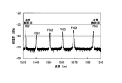
- FIG. 6 shows the reflection spectra of the reference FBGs 1 and 2 and FBGs 1 to 4 measured at room temperature (295 K) and no strain using the measuring instrument described above.
- the Bragg wavelengths of FBGs 1 to 4 obtained from this reflection spectrum were 1540.367 nm for FBG1, 1550.634 nm for FBG2, 1560.660 nm for FBG3, and 1569.300 nm for FBG4.
- FIG. 7A shows a schematic configuration of the test apparatus 20 used in this embodiment. 7B, in the superconducting wire 1 in which the optical fiber 3 in which a plurality of fiber Bragg gratings 4 are formed is bonded and fixed, a heater 6 for generating a normal conducting transition of the superconducting wire 1 is provided in the vicinity of the optical fiber 3.
- a heater 6 for generating a normal conducting transition of the superconducting wire 1 is provided in the vicinity of the optical fiber 3.
- An example of the configuration is shown.
- the superconducting wire 1 was fixed in a coil shape to a cylindrical jig 24 and cooled in a cryogenic vessel 25.
- the inside of the cryogenic container 25 is hermetically sealed by a container body 25a and a lid 25b, and is thermally insulated by vacuum evacuation by a vacuum pump (not shown), and the cooling performance of a refrigerator (not shown) that cools the inside of the cryogenic container 25. Is increasing.
- the superconducting wire 1 was cooled to a predetermined temperature in the cryocontainer 25 using a refrigerator and a semiconductor temperature sensor (Cellnox thermometer: trade name, not shown) provided thereon.
- the optical fiber 3 adhered and fixed to the superconducting wire 1 was taken out of the cryogenic vessel 25 through a vacuum feedthrough that can connect the optical fibers, and the terminal was connected to the temperature measuring instrument 10.
- the heater 6 installed on the superconducting wire 1 is a heater for heating the superconducting wire 1. When the heater 6 is energized, the temperature of the superconducting wire 1 can be raised to a temperature equal to or higher than the critical temperature of the superconducting layer 1b, and a normal conducting transition can be intentionally generated.
- the electrodes 23 provided at both ends of the superconducting wire 1 are connected via a vacuum feedthrough capable of connecting the power cables 22 to each other, and the superconducting wire 1 can be energized from the current terminal of the power source 21.
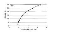
- FIG. 8 shows the relationship between the absolute temperature of the FBG 1 and the Bragg wavelength shift, and the sensitivity (the Bragg wavelength shift amount per unit temperature change) obtained from this Bragg wavelength shift characteristic.
- the sensitivity (indicated by a line without the symbol ( ⁇ ) in FIG.
- Equation (2) is the result obtained by approximating the relationship between the absolute temperature (x) and the Bragg wavelength shift (y) shown in Equation (2) with a quartic equation as x. Obtained by differentiating. This result can be expressed by equation (3).
- the units in the formulas (2) and (3) are absolute temperature (x) K, wavelength shift (y) pm, and sensitivity (y ′) pm / K.
- Example 2 of temperature measurement method In the above described (Embodiment 1 of the temperature measurement method), the temperature is calculated using the approximate expression obtained for each FBG. However, the temperature may be calculated using one approximate expression given in advance. . Table 2 shows the results of calculating the temperature using the above equations (4) to (7) with respect to the wavelength shift of the FBG 1. Since the equation (4) is a relational expression between the absolute temperature and the Bragg wavelength shift obtained in the experiment using the FBG1, the same result as in Table 1 is obtained, but it is obtained in the experiment using the FBGs 2 to 4. Even using the equations (5) to (7), a measurement accuracy of ⁇ 20 K was obtained in the temperature range of 25 to 295 K.
- FIG. 13 is a diagram in which the results of FIGS. 9 to 12 are plotted in one graph.
- FBGs 1 to 4 indicate that the relationship between the Bragg wavelength shift and the temperature change is very close. Further, in the normal conduction transition detection at 77K to be performed thereafter, it is considered that the temperature measurement accuracy is about ⁇ 20K. Although the temperature accuracy is inferior to the case of calculating from the approximate expression obtained by each FBG in the above (Example 1 of temperature measurement method), by using one approximate expression given in advance, for each FBG This method is useful in that it is not necessary to previously calculate the relationship between absolute temperature and Bragg wavelength shift.
- Example 1 of detection method of normal conduction transition Next, using the test apparatus shown in FIG. 7A and FIG. 7B, the normal conducting transition is intentionally generated for the superconducting wire 1 of the present embodiment, the normal conducting transition is detected by FBG, and the temperature generated at this time is detected. Measurement was performed.
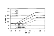
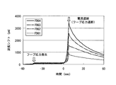
- the superconducting wire 1 is cooled and held at 77 K, which is lower than the critical temperature of the superconducting layer, and the superconducting layer 1 is locally heated by energizing the heater 6 for 3 seconds with a current of 160 A being passed through the superconducting layer. This is the result of measuring the wire temperature at each of the FBGs 1 to 4.
- the FBG 4 adjacent to the heater 6 detected the heat generation earliest, and the FBG 1 far from the heater 6 detected the heat generation the latest.
- the time when the FBG 4 adjacent to the heater 6 detects heat generation is defined as 0 seconds, and when the heat generation of the FBG 1 far from the heater 6 is detected and time sufficiently passes, it is 2.1 seconds.
- the electric current supplied to the superconducting wire 1 is interrupted. This result indicates that the normal conduction transition generated in the heater 6 propagates in the longitudinal direction of the superconducting wire 1.
- the detection time difference of each FBG shows the propagation speed of a normal conduction transition, and the inclination of a wire temperature change shows a temperature rise rate.
- the propagation speed obtained from this result was about 25 mm / s, and the temperature rise speed was about 80 K / s. From these speeds, the maximum temperature generated at the starting point of the normal conduction transition, that is, at the center of the heater 6, can be obtained using the equation (8).
- 10 mm is the distance between the FBG 4 and the heater 6, and 245K is the maximum temperature measured by the FBG 4 shown in FIG. Since the result of Equation (8) is 277K and the temperature measurement accuracy at 77 to 295K obtained in advance is ⁇ 5K, it can be estimated that the maximum temperature generated in the wire is about 277 ⁇ 5K.
- the propagation speed of the normal conduction transition and the temperature rise speed of the superconducting wire can be measured. Further, the maximum temperature at the starting point of the normal conduction transition, that is, the maximum temperature generated in the superconducting wire can be measured from these speeds. From the comparison between the maximum temperature and a preset safety reference temperature, it is possible to determine the necessity for inspection and repair of the superconducting wire.
- FIG. 15 is a result of measuring the wire temperature by FBG when the superconducting wire 1 is locally heated by energizing the heater for 1.5 seconds.
- the time when the FBG 4 detects heat generation is defined as 0 seconds, and the current flowing through the superconducting wire 1 is cut off at 1.1 seconds.
- the rate of temperature increase was about 80 K / s for FBG4, about 65 K / s for FBG3, about 40 K / s for FBG2, and about 15 K / s for FBG1.
- the range showing the normal conduction transition in this embodiment is from the center of the heater to the FBG 3 and the distance is about 20 mm.
- the range in which the normal conduction transition is actually performed is about 40 mm.
- the normal conducting transition range can be detected. Therefore, even if it is determined that inspection or repair of the superconducting wire is necessary, the range can be limited, and the work efficiency can be improved.
- any one of the FBGs FBG4 detects heat generation, and then interrupts the current that is applied to the superconducting wire 1 at an early stage. It can be seen that the range of the normal conducting transition can be reduced.
- a control device that controls the amount of current supplied to the superconducting wire by limiting (decreasing) or interrupting (stopping) the current, and an alarm device that issues an alarm to the worker when an abnormality is detected
- a control device that controls the amount of current supplied to the superconducting wire by limiting (decreasing) or interrupting (stopping) the current
- an alarm device that issues an alarm to the worker when an abnormality is detected
- FIG. 16 is a graph showing changes over time in the wire temperature measured by the FBG 4 when the current supplied to the superconducting wire is changed to 160A, 190A, and 220A and the heater is supplied for 1.5 seconds.
- the plot of 160A cites the result of Example 2 (FIG. 15).
- the time when the FBG 4 detects heat generation is defined as 0 seconds, and the current flowing to the superconducting wire 1 is cut off when the FBG reaches 150K or more.
- the rate of temperature increase was about 80 K / s at 160 A, about 140 K / s at 190 A, and about 160 K / s at 220 A.
- FIG. 17 is a graph showing the relationship between the square value of the current passed through the superconducting wire 1 and the temperature rise rate.
- the rate of temperature increase increased almost in direct proportion to the square value of the current passed through the superconducting wire 1.
- current value current value is I
- R resistance value
- the generated Joule heat is directly proportional to R ⁇ I 2 . That is, the reason why the rate of temperature rise is directly proportional to the square value of the current passed through the superconducting wire is that the heat generated in the normal conducting transition portion is caused by Joule heat generated in the metal stabilizing layer.
- the temperature increase due to the normal conduction transition increases as the value of the current applied to the superconducting wire increases. It is necessary to consider that the speed increases.
- the maximum temperature measured on the FBG 4 is about 160 to 170 K, but the maximum temperature at the starting point 2 is the same as in the above (Example 1 of the normal conduction transition detection method). As a result of the estimation, a result is obtained that the higher the current value, the higher the maximum temperature at the starting point.
- the superconducting wire 1 is fixed in a coil shape, but the present invention is not limited to these embodiments.
- the superconducting wire that converts a superconducting wire into a cable and transmits a large current is used. It can also be used for cables.
- Example 4 of detection method of normal conduction transition
- the superconducting wire 1 was cooled and held at 50K, and a 3T magnetic field was applied to an electromagnet (not shown) provided on the outer periphery of the superconducting wire 1.
- the critical current of the superconducting wire 1 at 50K and 3T is about 200A.
- an electromagnetic force hoop stress
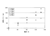
- FIG. 18 is a graph showing changes in the Bragg wavelengths of the FBGs 1 to 4 when the value of the current applied to the superconducting wire 1 is changed to 40A, 80A, 120A, and 140A.
- a tensile strain is generated in the longitudinal direction of the superconducting wire 1, so that the tensile strain is transmitted to the FBGs 1 to 4. Therefore, the lattice spacing ⁇ of the FBG is extended, and the Bragg wavelength ⁇ B is shifted to the long wavelength side. It has been confirmed that the value of the current applied to the superconducting wire 1 and the change in the Bragg wavelength are almost directly proportional to the value of the current applied to the superconducting wire 1, although there is a slight difference between FBGs 1 to 4.
- FIG. 19 shows the result of measuring the change in the Bragg wavelength of each of the FBGs 1 to 4 at this time.
- FIG. 20 is an enlarged graph of the section of ⁇ 2 to 12 seconds in FIG.
- the time when the Bragg wavelength of the FBG 4 has greatly changed is defined as 0 seconds, and the current supplied to the superconducting wire 1 is cut off at the time of 8 seconds.
- FIG. 21 shows the result of the Bragg wavelength shift obtained by subtracting the Bragg wavelength shift caused by the hoop stress.
- the temperature of the superconducting wire 1 is obtained based on the Bragg wavelength shift obtained in FIG. From the relationship between the absolute temperature and the Bragg wavelength shift obtained in advance in Example 1, the relationship between the wavelength shift from 50K and the absolute temperature is obtained, and a result obtained by approximating this to a quartic function and the correlation function (R 2 ) of this approximate expression Is shown in equations (9) to (12).
- the units in the equations (9) to (12) are K for the absolute temperature (y) and nm for the wavelength shift (x).
- FIG. 21 The Bragg wavelength shift obtained in FIG. 21 was converted into the temperature of the superconducting wire 1 using the mathematical formulas (9) to (12) obtained above.
- FIG. 22 is a graph showing the results converted to the temperature of the superconducting wire 1.
- the temperature change generated in the superconducting wire 1 could be accurately obtained without converting the Bragg wavelength shift due to the hoop stress as a temperature.
- the propagation speed obtained from this result was about 11 mm / s, and the temperature rise rate was about 25 K / s.
- the maximum temperature was estimated at 284K.
- an electromagnetic force (hoop stress) was generated by the electromagnet provided on the outer periphery of the superconducting wire 1, but a large coil was produced using a long superconducting wire and a current was passed through the hoop.
- the present invention can also be used when stress is generated.
Landscapes
- Physics & Mathematics (AREA)
- General Physics & Mathematics (AREA)
- Biochemistry (AREA)
- Life Sciences & Earth Sciences (AREA)
- Chemical & Material Sciences (AREA)
- Analytical Chemistry (AREA)
- Health & Medical Sciences (AREA)
- General Health & Medical Sciences (AREA)
- Immunology (AREA)
- Pathology (AREA)
- Superconductors And Manufacturing Methods Therefor (AREA)
- Measuring Temperature Or Quantity Of Heat (AREA)
- Investigating Or Analyzing Materials Using Thermal Means (AREA)
Abstract
この超電導線材の常電導転移の検出方法は、基材と、77K以上の臨界温度を有する超電導層と、金属安定化層とを備える超電導線材の常電導転移の検出方法であって、コアにその長手方向に沿って複数のファイバブラッググレーティングが形成された光ファイバを前記超電導線材に接着固定し;前記超電導線材の温度変化に対する前記ファイバブラッググレーティングのブラッグ波長の変化をあらかじめ測定し、前記ブラッグ波長の変化から前記超電導線材の温度を計測するための関係式を求め;前記超電導線材に常電導転移が生じる前後の前記複数のファイバブラッググレーティングの温度変化を、前記関係式により求め;前記複数のファイバブラッググレーティングの温度上昇が開始した時間差と、前記複数のファイバブラッググレーティングの間隔とに基づいて、前記常電導転移の伝播速度を算出する。
Description
本発明は、超電導線材の常電導転移の検出方法に関する。
本願は、2011年3月16日に、日本に出願された特願2011-057939号、及び2010年6月28日に、日本に出願された特願2010-146304号に基づき優先権を主張し、その内容をここに援用する。
本願は、2011年3月16日に、日本に出願された特願2011-057939号、及び2010年6月28日に、日本に出願された特願2010-146304号に基づき優先権を主張し、その内容をここに援用する。
超電導線材は、例えば核磁気共鳴画像装置や磁気浮上式鉄道、磁気軸受、電動機等の超電導磁石や超電導ケーブルへの応用が期待されており、その実用化に向けて、超電導線材の運転中の信頼性を確保する研究が盛んに行われている。
超電導線材を構成する超電導体は、一般に臨界温度(超電導性を示す上限の温度)が常温よりも低いため、液体ヘリウムや液体窒素等の冷却媒体や冷凍機等を用いて臨界温度以下まで冷却して使用される。しかしながら、超電導線材を外部から臨界温度以下に冷却しても、通電時に超電導線材の一部に熱攪乱が生じること等の原因で超電導状態から常電導状態へ遷移する常電導転移が発生すると、ジュール熱が発生して超電導線材の温度が上昇し、その周囲の常電導転移を促進して常電導状態の領域が拡大する問題(クエンチ現象)がある。
特許文献1には、超電導体が熱攪乱等により常電導状態に転移したクエンチする直前の僅かな温度上昇を検出するため、超電導体上にカーボン膜を設け、カーボン膜の電圧から微小な温度変化を検知する方法が記載されている。しかしながら、特許文献1に記載の方法は、液体ヘリウムの温度から数K(ケルビン)程度という極低温領域ではカーボン膜の温度に対する電気抵抗値が著しく大きいという性質(特許文献1の図7参照)を利用するものである。このため、臨界温度が77K以上(例えば100K程度)の高温超電導体に適用することは困難である。
特許文献2には、超電導線材に巻き付いた光ファイバーに光源から偏光光線を入射させ、この光ファイバーからの偏光の位相差を検出し、光ファイバー中を透過した光の偏光状態の異常を検出する超電導体クエンチ検出方法が記載されている。
また、特許文献3(特にその第四の発明)には、光ファイバーが超電導線の外部に取り付けられ、通電時の超電導線における異常部分の機械的変位による光ファイバーの変形部分からの反射光または光ファイバーの他端からの透過光を測定して、超電導線の異常を検知する超電導線のクエンチ検出方法が記載されている。
しかしながら、特許文献2,3に記載の方法は、クエンチを原因として超電導線材が動き、光ファイバの位置ズレや変形が増大することにより、光ファイバの異常の有無を判定することができるだけであり、温度変化の詳細を計測することはできない。
また、特許文献3(特にその第四の発明)には、光ファイバーが超電導線の外部に取り付けられ、通電時の超電導線における異常部分の機械的変位による光ファイバーの変形部分からの反射光または光ファイバーの他端からの透過光を測定して、超電導線の異常を検知する超電導線のクエンチ検出方法が記載されている。
しかしながら、特許文献2,3に記載の方法は、クエンチを原因として超電導線材が動き、光ファイバの位置ズレや変形が増大することにより、光ファイバの異常の有無を判定することができるだけであり、温度変化の詳細を計測することはできない。
特許文献4および非特許文献1には、ファイバブラッググレーティング(FBG)を用いた光ファイバ型温度センサによる極低温での温度計測方法が記載されている。FBGとは、光ファイバのコアに周期的な屈折率変化(グレーティング)を形成した光ファイバ型デバイスであり、コアの屈折率とグレーティングの周期で決まる特定の波長(ブラッグ波長)を選択的に反射する性質を有する。
特許文献4では、光ファイバのFBGの周囲に、光ファイバの主成分であるシリカよりも熱膨張係数(TEC)の大きいアルミニウム(Al)やポリメチルメタクリレート(PMMA)等の被覆材(コーティング)を設けて、温度によるブラッグ波長の変化を増大させることで温度センサの感度を向上している。また、非特許文献1では、ひずみ、温度、線膨張の計測例が示されている。
特許文献4では、光ファイバのFBGの周囲に、光ファイバの主成分であるシリカよりも熱膨張係数(TEC)の大きいアルミニウム(Al)やポリメチルメタクリレート(PMMA)等の被覆材(コーティング)を設けて、温度によるブラッグ波長の変化を増大させることで温度センサの感度を向上している。また、非特許文献1では、ひずみ、温度、線膨張の計測例が示されている。
Wolfgang Eckeら、"Fiber optic grating sensors for structural health monitoring at cryogenic temperatures"、Proc. SPIE、2007年、Vol.6530、653002.
特許文献4および非特許文献1では、被覆材を設けたFBGを用いて、例えば特許文献4のFIG.21に示されているように、被覆材を設けたFBGが均質な媒質中に浸漬されている場合にその媒質の温度を計測できることが記載されているのみである。
また、特許文献4に記載されたFBGを、高温超電導体の温度計測に用いる場合、線材化された高温超電導体は変形性に乏しいため、被覆材の周囲全体に超電導線材を配置させることはできない。すなわち、被覆材を設けたFBGの周囲の媒質を均質にすることができない。また、線材からの熱伝導性を考慮して、光ファイバ周囲の被覆材を超電導線材に密着させたとしても、被覆材の熱膨張係数と超電導線材の熱膨張係数との違いのため、被覆材の伸縮が制限を受ける。このため、温度計測の精度や応答速度に悪影響を与えるおそれがある。
また、特許文献4に記載されたFBGを、高温超電導体の温度計測に用いる場合、線材化された高温超電導体は変形性に乏しいため、被覆材の周囲全体に超電導線材を配置させることはできない。すなわち、被覆材を設けたFBGの周囲の媒質を均質にすることができない。また、線材からの熱伝導性を考慮して、光ファイバ周囲の被覆材を超電導線材に密着させたとしても、被覆材の熱膨張係数と超電導線材の熱膨張係数との違いのため、被覆材の伸縮が制限を受ける。このため、温度計測の精度や応答速度に悪影響を与えるおそれがある。
本発明は、上記事情に鑑みてなされたものであり、常電導転移に伴う温度変化を良好な精度や応答性で検出するとともに、超電導線材の温度変化に基づいて常電導転移が発生した超電導線材の状態をより精密に検出することが可能な超電導線材の常電導転移の検出方法を提供することを課題とする。
前記課題を解決するため、本発明は以下の構成を採用した。
本発明の第1の態様に係る超電導線材の常電導転移の検出方法は、基材と、77K以上の臨界温度を有する超電導層と、金属安定化層とを備える超電導線材の常電導転移の検出方法であって、コアにその長手方向に沿って複数のファイバブラッググレーティングが形成された光ファイバを前記超電導線材に接着固定し;前記超電導線材の温度変化に対する前記ファイバブラッググレーティングのブラッグ波長の変化をあらかじめ測定し、前記ブラッグ波長の変化から前記超電導線材の温度を計測するための関係式を求め;前記超電導線材に常電導転移が生じる前後の前記複数のファイバブラッググレーティングの温度変化を、前記関係式により求め;前記複数のファイバブラッググレーティングの温度上昇が開始した時間差と、前記複数のファイバブラッググレーティングの間隔とに基づいて、前記常電導転移の伝播速度を算出する。
上記本発明の第1の態様に係る超電導線材の常電導転移の検出方法においては、前記複数のファイバブラッググレーティングのいずれかにおいて計測した最高温度をTmax、このファイバブラッググレーティングから前記常電導転移の起点部までの距離をL、このファイバブラッググレーティングにおける温度上昇速度をυ、前記常電導転移の伝播速度をVとして、前記常電導転移の起点部における最高温度を、(L/V)υ+Tmaxにより算出してもよい。
上記本発明の第1の態様に係る超電導線材の常電導転移の検出方法においては、前記最高温度Tmaxおよび前記温度上昇速度υを、前記常電導転移の起点部に最も近いファイバブラッググレーティングを用いて計測してもよい。
上記本発明の第1の態様に係る超電導線材の常電導転移の検出方法においては、前記複数のファイバブラッググレーティングのそれぞれにおける温度上昇速度を、各ファイバブラッググレーティングの温度変化から求め、前記温度上昇速度が所定のしきい値以上であることにより、このファイバブラッググレーティングの位置に前記常電導転移が伝播したことを確認してもよい。
上記本発明の第1の態様に係る超電導線材の常電導転移の検出方法においては、前記所定のしきい値は、前記超電導線材に通電する電流値ごとにあらかじめ設定されてもよい。
本発明の第1の態様に係る超電導線材の常電導転移の検出方法は、基材と、77K以上の臨界温度を有する超電導層と、金属安定化層とを備える超電導線材の常電導転移の検出方法であって、コアにその長手方向に沿って複数のファイバブラッググレーティングが形成された光ファイバを前記超電導線材に接着固定し;前記超電導線材の温度変化に対する前記ファイバブラッググレーティングのブラッグ波長の変化をあらかじめ測定し、前記ブラッグ波長の変化から前記超電導線材の温度を計測するための関係式を求め;前記超電導線材に常電導転移が生じる前後の前記複数のファイバブラッググレーティングの温度変化を、前記関係式により求め;前記複数のファイバブラッググレーティングの温度上昇が開始した時間差と、前記複数のファイバブラッググレーティングの間隔とに基づいて、前記常電導転移の伝播速度を算出する。
上記本発明の第1の態様に係る超電導線材の常電導転移の検出方法においては、前記複数のファイバブラッググレーティングのいずれかにおいて計測した最高温度をTmax、このファイバブラッググレーティングから前記常電導転移の起点部までの距離をL、このファイバブラッググレーティングにおける温度上昇速度をυ、前記常電導転移の伝播速度をVとして、前記常電導転移の起点部における最高温度を、(L/V)υ+Tmaxにより算出してもよい。
上記本発明の第1の態様に係る超電導線材の常電導転移の検出方法においては、前記最高温度Tmaxおよび前記温度上昇速度υを、前記常電導転移の起点部に最も近いファイバブラッググレーティングを用いて計測してもよい。
上記本発明の第1の態様に係る超電導線材の常電導転移の検出方法においては、前記複数のファイバブラッググレーティングのそれぞれにおける温度上昇速度を、各ファイバブラッググレーティングの温度変化から求め、前記温度上昇速度が所定のしきい値以上であることにより、このファイバブラッググレーティングの位置に前記常電導転移が伝播したことを確認してもよい。
上記本発明の第1の態様に係る超電導線材の常電導転移の検出方法においては、前記所定のしきい値は、前記超電導線材に通電する電流値ごとにあらかじめ設定されてもよい。
本発明の第2の態様に係る超電導線材の常電導転移の検出方法は、基材と、77K以上の臨界温度を有する超電導層と、金属安定化層とを備える超電導線材の常電導転移の検出方法であって、コアにその長手方向に沿って複数のファイバブラッググレーティングが形成された光ファイバを前記超電導線材に接着固定し;前記超電導線材の温度変化に対する前記ファイバブラッググレーティングのブラッグ波長の変化をあらかじめ測定し、前記ブラッグ波長の変化から前記超電導線材の温度を計測するための関係式を求め;前記超電導線材に常電導転移が生じる前後の前記複数のファイバブラッググレーティングの温度変化を、前記関係式により求め;前記複数のファイバブラッググレーティングのそれぞれにおける温度上昇速度を、各ファイバブラッググレーティングの温度変化から求め;前記温度上昇速度が所定のしきい値以上であるか否かにより、このファイバブラッググレーティングの位置に前記常電導転移が伝播したか否かを判定する。
上記本発明の第2の態様に係る超電導線材の常電導転移の検出方法においては、前記常電導転移が伝播したと判定されたファイバブラッググレーティングのうち、前記常電導転移の起点部から最も遠いファイバブラッググレーティングまでの距離を2倍することにより、前記常電導転移が生じた範囲を推定してもよい。
上記本発明の第2の態様に係る超電導線材の常電導転移の検出方法においては、前記所定のしきい値は、前記超電導線材に通電する電流値ごとにあらかじめ設定されてもよい。
上記本発明の第2の態様に係る超電導線材の常電導転移の検出方法においては、前記超電導線材がコイル状であり、このコイルにより発生させる電磁力によるファイバブラッググレーティングのブラッグ波長の変化をあらかじめ測定し、前記電磁力によるファイバブラッググレーティングのブラッグ波長の変化を減算して得られるブラッグ波長の変化を前記関係式に適用して、前記超電導線材に常電導転移が生じる前後の前記複数のファイバブラッググレーティングの温度変化を求めてもよい。
前記複数のファイバブラッググレーティングが形成された光ファイバは、広帯域光源と、分光素子と、前記広帯域光源からの測定光が前記光ファイバに入射されるとともに、前記複数のファイバブラッググレーティングからのブラッグ反射光を前記分光素子に入射する光部品と、前記分光素子により分光された光を受光して電圧信号を出力する受光素子とを備える温度計測器に接続されていてもよい。
上記本発明の第2の態様に係る超電導線材の常電導転移の検出方法においては、前記常電導転移が伝播したと判定されたファイバブラッググレーティングのうち、前記常電導転移の起点部から最も遠いファイバブラッググレーティングまでの距離を2倍することにより、前記常電導転移が生じた範囲を推定してもよい。
上記本発明の第2の態様に係る超電導線材の常電導転移の検出方法においては、前記所定のしきい値は、前記超電導線材に通電する電流値ごとにあらかじめ設定されてもよい。
上記本発明の第2の態様に係る超電導線材の常電導転移の検出方法においては、前記超電導線材がコイル状であり、このコイルにより発生させる電磁力によるファイバブラッググレーティングのブラッグ波長の変化をあらかじめ測定し、前記電磁力によるファイバブラッググレーティングのブラッグ波長の変化を減算して得られるブラッグ波長の変化を前記関係式に適用して、前記超電導線材に常電導転移が生じる前後の前記複数のファイバブラッググレーティングの温度変化を求めてもよい。
前記複数のファイバブラッググレーティングが形成された光ファイバは、広帯域光源と、分光素子と、前記広帯域光源からの測定光が前記光ファイバに入射されるとともに、前記複数のファイバブラッググレーティングからのブラッグ反射光を前記分光素子に入射する光部品と、前記分光素子により分光された光を受光して電圧信号を出力する受光素子とを備える温度計測器に接続されていてもよい。
本発明の態様に係る超電導線材の常電導転移の検出方法によれば、超電導線材の温度変化に対するFBGのブラッグ波長の変化をあらかじめ測定し、ブラッグ波長の変化から超電導線材の温度を計測するための関係式を用いて超電導線材の温度変化を計測することにより、常電導転移に伴う温度変化を高い応答性で検出することが可能になる。
光ファイバの長手方向に沿って複数のFBGを形成し、これらのFBGにおいて温度上昇が開始した時間差を測定することにより、この時間差と、複数のFBGの間隔とから、常電導転移の伝播速度を算出することができる。
いずれかのFBGにおいて計測した最高温度と、FBGから常電導転移の起点部までの距離と、FBGにおける温度上昇速度と、常電導転移の伝播速度とを測定することにより、常電導転移の起点部における最高温度を求めることも可能である。
FBGの位置まで常電導転移が伝播すると、そうでない場合に比べて温度上昇速度が大きくなることを利用することにより、FBGの温度上昇速度から常電導転移が伝播したか否かを判定することも可能である。
常電導転移が伝播したと判定されたFBGのうち、常電導転移の起点部から最も遠いFBGまでの距離に基づいて、常電導転移が生じた範囲を推定することも可能である。
超電導線材がコイル状であり、このコイルに電磁力が発生する場合には、電磁力によるFBGのブラッグ波長の変化を減算した結果を用いることにより、電磁力によるブラッグ波長の変化を温度変化として換算することなく、超電導線材に生じる温度変化をより正確に求めることができる。
光ファイバの長手方向に沿って複数のFBGを形成し、これらのFBGにおいて温度上昇が開始した時間差を測定することにより、この時間差と、複数のFBGの間隔とから、常電導転移の伝播速度を算出することができる。
いずれかのFBGにおいて計測した最高温度と、FBGから常電導転移の起点部までの距離と、FBGにおける温度上昇速度と、常電導転移の伝播速度とを測定することにより、常電導転移の起点部における最高温度を求めることも可能である。
FBGの位置まで常電導転移が伝播すると、そうでない場合に比べて温度上昇速度が大きくなることを利用することにより、FBGの温度上昇速度から常電導転移が伝播したか否かを判定することも可能である。
常電導転移が伝播したと判定されたFBGのうち、常電導転移の起点部から最も遠いFBGまでの距離に基づいて、常電導転移が生じた範囲を推定することも可能である。
超電導線材がコイル状であり、このコイルに電磁力が発生する場合には、電磁力によるFBGのブラッグ波長の変化を減算した結果を用いることにより、電磁力によるブラッグ波長の変化を温度変化として換算することなく、超電導線材に生じる温度変化をより正確に求めることができる。
以下、本発明の一実施形態を、図面を参照して説明する。
図3に複数のファイバブラッググレーティング4が形成された光ファイバ3を用いた温度計測器10の一例を示す。また、図4に、光ファイバ3を超電導線材1の金属安定化層1c上に接着固定した状態の一例を示す。
図3に複数のファイバブラッググレーティング4が形成された光ファイバ3を用いた温度計測器10の一例を示す。また、図4に、光ファイバ3を超電導線材1の金属安定化層1c上に接着固定した状態の一例を示す。
《超電導線材》
超電導線材1は、基材1aと、77K以上の臨界温度を有する超電導層1bと、金属安定化層1cを少なくとも備えて構成されている。
本実施形態の超電導線材1に適用できる基材1aは、通常の超電導線材の基材として使用でき、高強度であれば良い。また、長尺のケーブルとするためにテープ状であることが好ましく、超電導体の成膜プロセス等に要求される耐熱性を備えた金属からなる基材が好ましい。例えば、銀、白金、ステンレス鋼、銅、ハステロイ(登録商標)等のニッケル合金等の各種金属材料、もしくはこれら各種金属材料上にセラミックスを配した基材等が挙げられる。各種耐熱性の金属の中でも、ニッケル合金が好ましい。なかでも、市販品であれば、ハステロイ(米国ヘインズ社製商品名)が好適であり、ハステロイとして、モリブデン、クロム、鉄、コバルト等の成分量が異なる、ハステロイB、C、G、N、W等のいずれの種類も使用できる。基材1aの厚さは、目的に応じて適宜調整すれば良く、通常は、10~500μmである。
超電導線材1は、基材1aと、77K以上の臨界温度を有する超電導層1bと、金属安定化層1cを少なくとも備えて構成されている。
本実施形態の超電導線材1に適用できる基材1aは、通常の超電導線材の基材として使用でき、高強度であれば良い。また、長尺のケーブルとするためにテープ状であることが好ましく、超電導体の成膜プロセス等に要求される耐熱性を備えた金属からなる基材が好ましい。例えば、銀、白金、ステンレス鋼、銅、ハステロイ(登録商標)等のニッケル合金等の各種金属材料、もしくはこれら各種金属材料上にセラミックスを配した基材等が挙げられる。各種耐熱性の金属の中でも、ニッケル合金が好ましい。なかでも、市販品であれば、ハステロイ(米国ヘインズ社製商品名)が好適であり、ハステロイとして、モリブデン、クロム、鉄、コバルト等の成分量が異なる、ハステロイB、C、G、N、W等のいずれの種類も使用できる。基材1aの厚さは、目的に応じて適宜調整すれば良く、通常は、10~500μmである。
超電導層1bを構成する超電導体は、77K以上の臨界温度を有していれば公知の超電導体で良く、具体的には、REBa2Cu3Oy(REはY、La、Nd、Sm、Er、Gd等の希土類元素を表す)で表される組成の超電導体を例示できる。この超電導層として、Y123(YBa2Cu3O7-X)又はGd123(GdBa2Cu3O7-X)などを例示することができる。また、その他の酸化物超電導体、例えば、Bi2Sr2Can-1CunO4+2n+δなる組成等に代表される臨界温度の高い他の酸化物超電導体からなる超電導体を用いても良い。
超電導層1bの厚みは、特に限定されるものではないが、例えば0.5~5μm程度であって、均一な厚みであることが好ましい。
超電導層1bの厚みは、特に限定されるものではないが、例えば0.5~5μm程度であって、均一な厚みであることが好ましい。
超電導層1bは、スパッタ法、真空蒸着法、レーザ蒸着法、電子ビーム蒸着法、パルスレーザ堆積法(PLD法)、イオンビームアシスト蒸着法(IBAD法)、化学気相成長法(CVD法)等で積層することができ、なかでも生産性の観点から、PLD法やIBAD法が好ましい。
また、金属有機酸塩を塗布後熱分解させる熱塗布分解法(MOD法)は、金属成分の有機化合物を均一に溶解した溶液を基材上に塗布した後、これを加熱して熱分解させることにより基材上に薄膜を形成する方法であり、真空プロセスを必要とせず、低コストで高速成膜が可能であるため長尺のテープ状超電導導体の製造に適している。
また、金属有機酸塩を塗布後熱分解させる熱塗布分解法(MOD法)は、金属成分の有機化合物を均一に溶解した溶液を基材上に塗布した後、これを加熱して熱分解させることにより基材上に薄膜を形成する方法であり、真空プロセスを必要とせず、低コストで高速成膜が可能であるため長尺のテープ状超電導導体の製造に適している。
超電導層1bの上に積層されている金属安定化層1cは、良導電性の金属材料からなり、超電導層1bが超電導状態から常電導状態に遷移しようとしたときに、超電導層1bの電流が転流するバイパスとして機能する。金属安定化層1cを構成する金属材料としては、良導電性を有する材料であればよく、特に限定されないが、銅、黄銅(Cu-Zn合金)等の銅合金、ステンレス等の比較的安価なものを用いるのが好ましく、中でも高い導電性を有し、安価であることから銅がより好ましい。これにより、材料コストを低く抑えながら金属安定化層1cを厚膜化することが可能となり、事故電流に耐える超電導線材1を安価に得ることができる。金属安定化層1cの厚さは、10~300μmとすることが好ましい。金属安定化層1cは、公知の方法で形成することができ、例えばスパッタ法や、銅などの金属テープを半田付けする方法により形成することができる。
基材1aと超電導層1bとの間には、拡散防止層、ベッド層、中間層、キャップ層等から選ばれる任意の層を1または2以上介在させても良い。
拡散防止層は、基材の構成元素の拡散を防止する目的で形成され、窒化ケイ素(Si3N4)、酸化アルミニウム(Al2O3)、あるいは希土類金属酸化物等から構成される。拡散防止層は、例えばスパッタリング法等の成膜法により形成され、その厚さは例えば10~400nmである。
ベッド層は、界面反応性を低減して、その上に配される膜の配向性を得る目的で形成され、例えば、酸化イットリウム(Y2O3)、窒化ケイ素(Si3N4)、酸化アルミニウム(Al2O3)等から構成される。ベッド層は、例えばスパッタリング法等の成膜法により形成され、その厚さは例えば10~200nmである。
拡散防止層は、基材の構成元素の拡散を防止する目的で形成され、窒化ケイ素(Si3N4)、酸化アルミニウム(Al2O3)、あるいは希土類金属酸化物等から構成される。拡散防止層は、例えばスパッタリング法等の成膜法により形成され、その厚さは例えば10~400nmである。
ベッド層は、界面反応性を低減して、その上に配される膜の配向性を得る目的で形成され、例えば、酸化イットリウム(Y2O3)、窒化ケイ素(Si3N4)、酸化アルミニウム(Al2O3)等から構成される。ベッド層は、例えばスパッタリング法等の成膜法により形成され、その厚さは例えば10~200nmである。
中間層は、超電導層の結晶配向性を制御するために2軸配向する物質から形成される。中間層は、単層構造あるいは複層構造のいずれでも良く、好ましい材質としては、例えばGd2Zr2O7、MgO、ZrO2-Y2O3(YSZ)、SrTiO3、CeO2、Y2O3、Al2O3、Gd2O3、Zr2O3、Ho2O3、Nd2O3等の金属酸化物が挙げられる。スパッタ法、真空蒸着法、レーザ蒸着法、電子ビーム蒸着法、イオンビームアシスト蒸着法(IBAD法)、化学気相成長法(CVD)等の物理的蒸着法、熱塗布分解法(MOD法)等の公知の方法で積層できる。中間層の厚さは、適宜調整できるが通常は0.005~2μmの範囲が好ましい。
キャップ層は、中間層の表面に対してエピタキシャル成長し、その後、横方向(面と平行な方向)に粒成長(オーバーグロース)して、結晶粒が面内方向に選択成長するという過程を経て形成されたキャップ層が好ましい。このようなキャップ層は、金属酸化物層からなる中間層よりも高い面内配向度が得られるため、超電導層をキャップ層の上に形成することが好ましい。キャップ層の材質は、上記機能を発現し得るものであれば特に限定されないが、好ましいものとして具体的には、CeO2、Y2O3、Al2O3、Gd2O3、Zr2O3、Ho2O3、Nd2O3等が例示できる。また、CeO2におけるCeの一部が他の金属原子又は金属イオンで置換されたCe-M-O系酸化物を含んでいても良い。
超電導層1bと金属安定化層1cとの間には、金属安定化基層として、Agなどの良電導性であり、かつ超電導層1bと接触抵抗(界面間の電気抵抗)が低く、なじみの良い金属材料からなる層を形成することもできる。金属安定化基層は、スパッタ法等の公知の方法で形成することができ、その厚さは1~30μmとすることが好ましい。
《光ファイバ》
本実施形態の超電導線材1に対して、光ファイバ3は、金属安定化層1cの上に接着固定される。光ファイバ3は、ファイバブラッググレーティング(FBG)を形成可能な公知の光ファイバであればよく、石英系のシングルモード光ファイバが好ましい。石英系光ファイバを構成する材質は、純石英ガラス、ゲルマニウム(Ge)等の屈折率を上昇する添加剤を用いた石英ガラス、フッ素(F)等の屈折率を下降する添加剤を用いた石英ガラスなどから適宜選択することが可能である。また、クラッドの周囲には、断面で同心円状となるように被覆材を設けることもできる。被覆材の具体例としては、ポリイミドなどの高ヤング率樹脂や、銅(Cu)、ニッケル(Ni)等の金属が挙げられ、後記する接着層5との密着性を考慮して選択することができる。
本実施形態の超電導線材1に対して、光ファイバ3は、金属安定化層1cの上に接着固定される。光ファイバ3は、ファイバブラッググレーティング(FBG)を形成可能な公知の光ファイバであればよく、石英系のシングルモード光ファイバが好ましい。石英系光ファイバを構成する材質は、純石英ガラス、ゲルマニウム(Ge)等の屈折率を上昇する添加剤を用いた石英ガラス、フッ素(F)等の屈折率を下降する添加剤を用いた石英ガラスなどから適宜選択することが可能である。また、クラッドの周囲には、断面で同心円状となるように被覆材を設けることもできる。被覆材の具体例としては、ポリイミドなどの高ヤング率樹脂や、銅(Cu)、ニッケル(Ni)等の金属が挙げられ、後記する接着層5との密着性を考慮して選択することができる。
光ファイバ3は、超電導線材1のうち金属安定化層1cに接触または近接して接着固定されば良い。接着層5の材質は、低温でも光ファイバ3を保護できるように、低温での耐久性が優れ、かつヤング率の高い材質が好ましい。接着層5としては、ポリイミド等の樹脂や接合用金属等が挙げられる。
光ファイバ3のコアにFBGを形成する方法としては、コアがGeを添加した石英系ガラスである場合には、例えばフッ化クリプトン(KrF)エキシマレーザや、アルゴン(Ar)のSHG(第2高調波)レーザを用い、位相マスク露光法や二光束干渉露光法等によりコアの長手方向に沿って所定の間隔で屈折率変化を誘起する方法が挙げられる。
グレーティング(回折格子)の周期(間隔)は、測定光の波長域の範囲内でブラッグ反射が生じるように光ファイバの屈折率等を考慮して設定することができる。例えば石英系光ファイバで1.5μm帯の測定光を用いる場合、グレーティングの周期は0.5μm程度が好ましい。
1つのグレーティングの長さ(グレーティング長)は、所望の反射率や反射帯域に応じて適宜選択することができ、例えば1~10mmが好ましい。
1つのグレーティングの長さ(グレーティング長)は、所望の反射率や反射帯域に応じて適宜選択することができ、例えば1~10mmが好ましい。
なお、回折格子の間隔をΛ、光の真空中波長をλ、光ファイバコアの屈折率をn、入射角θ、任意の正の整数をNとすると、ブラッグ反射が起こる条件は、2Λsinθ=Nλ/nであるから、θを直角(sinθ=1)とし、整数Nを1とすれば、格子間隔Λとブラッグ波長λBとの間には、λB=2nΛの関係がある。
このFBGに温度変化が生じると、屈折率nや格子間隔Λが変化することでブラッグ波長λBが変化する。屈折率nの変化は光ファイバコアの材質に依存し、光ファイバ3の被覆材や接着固定される対象物にはほとんど依存しない。一方、格子間隔Λの変化は、光ファイバ3の長手方向に沿った変形(伸縮)によって起こるため、光ファイバ3の被覆材や接着固定される対象物に依存する。
FBGを形成した光ファイバ3が超電導線材1に接着固定されていると、光ファイバ3を構成する石英系ガラス自体の線膨張係数が小さいとしても、超電導線材1を構成する部材の線膨張係数が大きいため、温度上昇時に大きな線膨張が発生する。つまり、温度上昇時には、超電導線材1の線膨張によりFBGの格子間隔Λが伸び、ブラッグ波長λBが長波長側にシフトする。
FBGを形成した光ファイバ3が超電導線材1に接着固定されていると、光ファイバ3を構成する石英系ガラス自体の線膨張係数が小さいとしても、超電導線材1を構成する部材の線膨張係数が大きいため、温度上昇時に大きな線膨張が発生する。つまり、温度上昇時には、超電導線材1の線膨張によりFBGの格子間隔Λが伸び、ブラッグ波長λBが長波長側にシフトする。
《超電導線材の温度計測方法》
本実施形態で用いられる超電導線材の温度計測方法では、コアに複数のFBGを形成した光ファイバ3を金属安定化層1c上に接着固定した状態で、超電導線材1の温度に対するFBGのブラッグ波長の変化をあらかじめ測定し、ブラッグ波長の変化から超電導線材1の温度を計測するための関係式を求めておく。これにより、計測時には、ブラッグ波長の変化から超電導線材1の温度をリアルタイムで計測することができる。
本実施形態で用いられる超電導線材の温度計測方法では、コアに複数のFBGを形成した光ファイバ3を金属安定化層1c上に接着固定した状態で、超電導線材1の温度に対するFBGのブラッグ波長の変化をあらかじめ測定し、ブラッグ波長の変化から超電導線材1の温度を計測するための関係式を求めておく。これにより、計測時には、ブラッグ波長の変化から超電導線材1の温度をリアルタイムで計測することができる。
この関係式は、ブラッグ波長の変化と超電導線材1の温度の相関性を表す関数であるから、あらかじめブラッグ波長変化の温度依存性(すなわち温度とブラッグ波長の変化の相関性)を表す関数を測定で求めておくことにより、その逆関数として導出することができる。
ブラッグ波長変化の温度依存性をあらかじめ測定することが必要な温度範囲は、超電導線材1の温度計測が必要とされる所定の温度範囲であり、超電導線材1が超電導状態で運転されるときの温度範囲と、超電導線材1の常電導転移が起こった後に到達し得る温度範囲を含むことが好ましい。
ブラッグ波長変化の温度依存性をあらかじめ測定することが必要な温度範囲は、超電導線材1の温度計測が必要とされる所定の温度範囲であり、超電導線材1が超電導状態で運転されるときの温度範囲と、超電導線材1の常電導転移が起こった後に到達し得る温度範囲を含むことが好ましい。
図3に示す温度計測器10は、複数のファイバブラッググレーティング4を形成した光ファイバ3と、広帯域光源11と、分光素子13と、広帯域光源11からの測定光を光ファイバ3に入射するとともに、複数のファイバブラッググレーティング4からのブラッグ反射光を分光素子13に入射する光部品12と、分光素子13により分光された光を受光して電圧信号を出力する受光素子14とを備える。光ファイバ3は、光源11に近い入射側が温度計測器10の光部品12に接続されている。
ブラッグ波長変化の温度依存性を測定するときは、超電導線材1の金属安定化層1c上に光ファイバ3を接着固定した状態で、周囲の温度を冷凍機などで変えながら、ブラッグ波長を測定する。
ブラッグ波長変化の温度依存性を測定するときは、超電導線材1の金属安定化層1c上に光ファイバ3を接着固定した状態で、周囲の温度を冷凍機などで変えながら、ブラッグ波長を測定する。
光源11は、各FBGが温度計測時に取りうるブラッグ波長の範囲全体を任意に出力することが可能な広帯域光源を用いることが好ましい。温度計測に必要な測定光の波長範囲が広い場合には、出力波長範囲の異なる複数の光源を組み合わせて、適宜の光源から光を光ファイバ3に入射させることでも対応可能である。
広帯域光源11と光ファイバ3との間に介在させる光部品12は、広帯域光源11からの測定光を光ファイバ3に入射するとともに、ブラッグ反射光を分光素子13に入射する機能を有する限り、特に限定されない。具体例としては、サーキュレータが挙げられる。光部品12はカプラでも良いが、反射光が光源11に戻るのを防ぐため、光を光源11から光部品12への方向にのみ透過させるアイソレータを設けることが好ましい。
図3に示すように、光源11から測定光を光ファイバ3に入射し、反射光のスペクトルを計測する。複数のFBGのブラッグ波長を区別するには、ブラッグ波長の値が互いに異なるようにすれば良い。ブラッグ波長には温度依存性があるので、各FBGが温度計測時に取りうるブラッグ波長の範囲が重ならない程度の波長差を設けることが好ましい。反射光のスペクトルは、所定の波長範囲内で透過波長を任意に選択可能な分光素子13を介して反射光を受光素子14で受光することで、光強度の波長依存性として計測することが可能である。
以上説明した温度計測器10に変わる手段として、光源11にチューナブルレーザを用い、分光素子13を用いることなくブラッグ反射光を受光素子14に入力する構成を用いることもできる。この場合、チューナブルレーザは、複数のFBGのブラッグ波長を計測可能な範囲で波長掃引することが望ましい。
また、温度計測器10を公知の時間分割多重(TDM)法や光周波数領域反射測定(OFDR)法に基づいた構成とすることで、ブラッグ波長が同一のFBGを超電導線材1の温度計測に用いることもできる。
以上説明した温度計測器10に変わる手段として、光源11にチューナブルレーザを用い、分光素子13を用いることなくブラッグ反射光を受光素子14に入力する構成を用いることもできる。この場合、チューナブルレーザは、複数のFBGのブラッグ波長を計測可能な範囲で波長掃引することが望ましい。
また、温度計測器10を公知の時間分割多重(TDM)法や光周波数領域反射測定(OFDR)法に基づいた構成とすることで、ブラッグ波長が同一のFBGを超電導線材1の温度計測に用いることもできる。
上述したように、光ファイバ3は超電導線材1に接着固定されており、温度変化にともなう超電導線材1の線膨張によりブラッグ波長が変化する。一般に超電導線材の基材や金属安定化層を構成する金属材料の線膨張係数の温度依存性は多項式で近似される(超電導層は、基材および金属安定化層と比較して十分に断面積が小さいので、超電導線材の線膨張係数は、これら金属材料の特性に支配される)。このため、ブラッグ波長の温度依存性を示す関係式を単純な1次式で表現すると、超電導体の臨界温度より低い温度から常温程度までの広い温度範囲を十分に近似することは難しい。そこで、例えば4次式など高次の数式を用いると、1つの数式で広い温度範囲を高精度に近似することができ、好ましい。この関係式は、1つの数式で表現する変わりに、定義域を複数の小範囲に分割して小範囲ごとに異なる1次式を用いた折れ線状の関数で表現することも可能である。
また、図3に示す温度計測器10は、超電導線材1の運転時に、光ファイバ3の各FBGのブラッグ波長を継続的に計測するためにも用いることができる。あらかじめブラッグ波長から温度への対応を表す関係式を求めてあるため、リアルタイムで計測されるブラッグ波長を即座に超電導線材1の温度として変換することができる。
臨界温度以下において超電導線材1に通電した場合、超電導層1bは超電導状態にあり、抵抗値が0であるため、電流はこの超電導層1bを流れ、超電導線材1は発熱しない。
超電導線材1において、万が一、何らかの理由により、超電導層1bが超電導状態から常電導状態に遷移する常電導転移が発生した場合、超電導層1bに抵抗が生じ、電流は抵抗が比較的小さい金属安定化層1cを流れる。その際、金属安定化層1cでは、電流値と抵抗値に応じたジュール熱が発生し、発熱が起こる。
超電導線材1において、万が一、何らかの理由により、超電導層1bが超電導状態から常電導状態に遷移する常電導転移が発生した場合、超電導層1bに抵抗が生じ、電流は抵抗が比較的小さい金属安定化層1cを流れる。その際、金属安定化層1cでは、電流値と抵抗値に応じたジュール熱が発生し、発熱が起こる。
この超電導線材の線膨張は、発熱に対して極めて速い時定数で発生する。本実施形態の超電導線材1は、万一、常電導転移が発生した場合にも、複数のFBGを形成した光ファイバ3が超電導線材1の金属安定化層1cに接着固定されていることにより、良好な精度および応答性で、超電導線材1内部の温度変化(温度上昇)を検知することができる。すなわち、本実施形態による超電導線材の温度計測方法は、極めて応答性の高い手法であるといえる。もちろん、光ファイバ3は、超電導線材1の線膨張が十分に伝達されれば良いので、基材1aの表面や超電導線材1の側面に接着固定しても構わない。
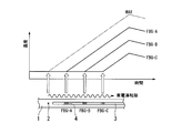
超電導線材1の常電導転移は、1箇所で発生すると、起点部2で生じたジュール熱がその周囲に熱伝導してさらに常電導転移を引き起こすため、常電導転移の範囲が超電導線材1の長手方向に沿って両側に拡大する。本実施形態では、光ファイバ3の長手方向に沿って複数のFBGを設けているので、図1や図2に示すように、常電導転移の起点部2から異なる複数の位置における温度変化(時間の経過に伴う温度の変化)を計測することができる。そして、これら複数のFBGにおける温度変化を比較することにより、常電導転移の発生状況や伝播状況を詳細に解析することが可能になる。
《常電導転移の伝播速度》
図1に示すように、超電導線材1に常電導転移が生じる前から後にわたって、各FBGの温度変化を継続的に計測すると、各FBGの温度上昇が開始した時間を求めることができる。具体的には、常電導転移が生じる前の時間範囲における温度変化をベースラインと考えれば、温度上昇の開始は、常電導転移が生じた後の温度変化(温度上昇)を表す線(またはその接線)がベースラインと交差する時間軸上の位置から求められる。
図1に示すように、超電導線材1に常電導転移が生じる前から後にわたって、各FBGの温度変化を継続的に計測すると、各FBGの温度上昇が開始した時間を求めることができる。具体的には、常電導転移が生じる前の時間範囲における温度変化をベースラインと考えれば、温度上昇の開始は、常電導転移が生じた後の温度変化(温度上昇)を表す線(またはその接線)がベースラインと交差する時間軸上の位置から求められる。
複数のFBGの温度上昇が開始した時間差と、複数のFBGの間隔とから、常電導転移の伝播速度を算出することができる。複数のFBGの間隔は、FBGを光ファイバのコアに形成する際、あらかじめ設定した値を用いることができ、既知である。FBGの個数が2つである場合は、FBGの間隔を温度上昇開始の時間差で除算して得られる商が、常電導転移の伝播速度に相当する。FBGの個数が3つ以上である場合には、平均をとる等の統計的手法により、同様に常電導転移の伝播速度を求めることができる。
《最高温度の推定》
超電導線材は冷却媒体や冷凍機を用いて冷却されているため、常電導転移が発生する前の超電導線材の温度は各所で略等しい。また、超電導線材の材質および構造はその長手方向全体にわたって略均一であるので、常電導転移が発生した箇所における温度上昇速度は各所で略等しい。なお、温度上昇速度は、単位時間当たりに上昇する温度差であり、例えば温度変化の時間微分を平均して求めることができる。
そこで、常電導転移が伝播したFBGにおける最高温度TmaxFBGは、常電導転移が発生する前の超電導線材1の温度をT0、常電導転移による温度上昇速度をυ、FBGの位置で温度上昇が開始してから最高温度に達するまでの時間差をΔt1として、TmaxFBG≒T0+υΔt1で近似して求めることができる。
超電導線材は冷却媒体や冷凍機を用いて冷却されているため、常電導転移が発生する前の超電導線材の温度は各所で略等しい。また、超電導線材の材質および構造はその長手方向全体にわたって略均一であるので、常電導転移が発生した箇所における温度上昇速度は各所で略等しい。なお、温度上昇速度は、単位時間当たりに上昇する温度差であり、例えば温度変化の時間微分を平均して求めることができる。
そこで、常電導転移が伝播したFBGにおける最高温度TmaxFBGは、常電導転移が発生する前の超電導線材1の温度をT0、常電導転移による温度上昇速度をυ、FBGの位置で温度上昇が開始してから最高温度に達するまでの時間差をΔt1として、TmaxFBG≒T0+υΔt1で近似して求めることができる。
また、常電導転移の起点部2で常電導転移が最初に発生してから起点部2に最も近いFBGで温度上昇が開始するまでの時間差Δt0は、常電導転移の伝播速度Vが一定とすると、常電導転移の起点部2からこのFBGまでの距離Lとにより、Δt0=L/Vで求めることができる。
さらに、温度上昇の終了は、例えば超電導線材1への通電の制限や遮断等、共通の原因によるため、超電導線材全体にわたって、ほぼ同時に起こる。つまり、常電導転移が最初に発生してから温度上昇が終了するまで時間差は、Δt0+Δt1となる。
さらに、温度上昇の終了は、例えば超電導線材1への通電の制限や遮断等、共通の原因によるため、超電導線材全体にわたって、ほぼ同時に起こる。つまり、常電導転移が最初に発生してから温度上昇が終了するまで時間差は、Δt0+Δt1となる。
このように常電導転移が発生した超電導線材の温度上昇過程をモデル化した場合、常電導転移の起点部2では、常電導転移が最初に発生してから温度上昇の終了時点までの間(Δt0+Δt1)、温度上昇速度υで温度上昇が継続することになるので、常電導転移の起点部2における最高温度TmaxOは、TmaxO≒T0+υ×(Δt0+Δt1)=(T0+υΔt1)+υΔt0≒TmaxFBG+υ×(L/V)で近似して求めることができる。
つまり、複数のFBGのいずれかにおいて計測した最高温度をTmax(上記TmaxFBGに相当)、このFBGから常電導転移の起点部2までの距離をL、このFBGにおける温度上昇速度をυ、常電導転移の伝播速度をVとして、常電導転移の起点部2における最高温度TmaxOは、(L/V)υ+Tmaxにより算出することができる。
なお、FBGにおける温度上昇速度υの値は、起点部2からの距離に応じて若干の差が出ることもあるため、常電導転移の起点部2における最高温度をより高精度に求めるには、起点部2に最も近いFBGによって計測した温度変化を用いることが好ましい。
なお、FBGにおける温度上昇速度υの値は、起点部2からの距離に応じて若干の差が出ることもあるため、常電導転移の起点部2における最高温度をより高精度に求めるには、起点部2に最も近いFBGによって計測した温度変化を用いることが好ましい。
《常電導転移の伝播範囲》
図2に示すように、温度上昇が比較的短時間で終了したために常電導転移が遠いFBGには到達しなかった場合、そのFBG(図2のFBG-C)では起点部2に近い側からの熱伝導による発熱が計測されることがある。しかしながら、熱伝導による発熱は、FBGの位置で常電導転移が発生しているときの発熱に比べて小さいため、両者は温度上昇速度の比較により区別することが可能である。
図2に示すように、温度上昇が比較的短時間で終了したために常電導転移が遠いFBGには到達しなかった場合、そのFBG(図2のFBG-C)では起点部2に近い側からの熱伝導による発熱が計測されることがある。しかしながら、熱伝導による発熱は、FBGの位置で常電導転移が発生しているときの発熱に比べて小さいため、両者は温度上昇速度の比較により区別することが可能である。
そこで、複数のFBGのそれぞれにおける温度上昇速度を、各FBGの温度変化から求め、温度上昇速度が所定のしきい値以上であるか否かであることにより、そのFBGの位置に常電導転移が伝播したか否かを判定することができる。
なお、上述したように常電導転移の伝播速度や最高温度を推定する場合には、推定に用いるFBGの位置まで常電導転移が伝播することが必要である。用いるFBGにおける温度上昇速度が所定のしきい値以上であれば、そのFBGの位置まで常電導転移が伝播したことを確認することができる。
なお、上述したように常電導転移の伝播速度や最高温度を推定する場合には、推定に用いるFBGの位置まで常電導転移が伝播することが必要である。用いるFBGにおける温度上昇速度が所定のしきい値以上であれば、そのFBGの位置まで常電導転移が伝播したことを確認することができる。
また、常電導転移が伝播したと判定されたFBGのうち、常電導転移の起点部2から最も遠いFBGまでの距離を2倍することにより、常電導転移が生じた範囲を推定することができる。図2に示す例では、常電導転移の起点部2から最も遠いFBGは、FBG-Bであるから、常電導転移の伝播範囲は、起点部2からFBG-Bまでの距離の2倍程度と推定することができる。
上述したように、常電導転移による発熱は、金属安定化層1cに流れる電流値と金属安定化層1cの抵抗値に応じたジュール熱が主であり、発熱量は電流値に強く依存するので、FBGの位置まで常電導転移が伝播したか否かを判定するための上記所定のしきい値は、超電導線材に通電する電流値ごとに異なる値を設定することが好ましい。
なお、熱伝導による発熱は、超電導線材1への通電の制限や遮断等が直接的に温度上昇を終了させるものではないため、熱伝導により発熱した領域が最大温度を示す時間は、いかなる場所でも一定とは限らない。この観点からも常電導転移の伝播範囲と熱伝導のみが生じた範囲とを区別することができる。
《超電導保護装置》
本実施形態の超電導線材の常電導転移の検出方法は、運転中の超電導線材の保護装置に利用することができる。
超電導保護装置は、図3の温度計測器10において、受光素子14から出力される電気信号を受け取って、上述の温度計測方法や常電導転移の検出方法に従って自動的に解析するコンピュータ等の解析装置、異常を検知した場合に電流を制限(低下)あるいは遮断(停止)させる等して超電導線材への通電量を制御する制御装置、異常を検知した場合に作業者に警報を発する警報装置、運転状況の表示装置、温度履歴の記録装置などを備えることができる。これにより、万一、常電導転移が発生しても超電導線材1の溶断や焼損を防止し、超電導線材1を良好な状態で保護することができる。
本実施形態の超電導線材の常電導転移の検出方法は、運転中の超電導線材の保護装置に利用することができる。
超電導保護装置は、図3の温度計測器10において、受光素子14から出力される電気信号を受け取って、上述の温度計測方法や常電導転移の検出方法に従って自動的に解析するコンピュータ等の解析装置、異常を検知した場合に電流を制限(低下)あるいは遮断(停止)させる等して超電導線材への通電量を制御する制御装置、異常を検知した場合に作業者に警報を発する警報装置、運転状況の表示装置、温度履歴の記録装置などを備えることができる。これにより、万一、常電導転移が発生しても超電導線材1の溶断や焼損を防止し、超電導線材1を良好な状態で保護することができる。
特に、常電導転移の起点部における最高温度や、常電導転移が生じた範囲を計測することにより、常電導転移による超電導線材へのダメージを定量的に認識することができるので、安全性を確認したのち、ダメージが軽微であれば超電導線材の交換を要せずして運転を再開することができる。
また、超電導線材の点検や交換が必要な場合でも、ダメージの程度に関する予備的な情報を得て作業を実施することができるので、より迅速かつ的確な作業が可能になる。
また、超電導線材の点検や交換が必要な場合でも、ダメージの程度に関する予備的な情報を得て作業を実施することができるので、より迅速かつ的確な作業が可能になる。
《超電導コイル》
本実施形態は、超電導線材をコイル状とし、超電導線材に電流を通電させることで電磁力(フープ応力)を発生することができる超電導コイルにも適用可能である。
超電導コイルは、例えば超電導線材をその厚さ方向に湾曲させ、同心円状に多数回巻回されてパンケーキ型のコイル体であっても良い。また、コイル体を2個または3個以上積層させても良い。
この場合、ブラッグ波長シフト(ブラッグ波長の変化)から超電導線材の温度を計測するための関係式を用いてブラッグ波長シフトを超電導線材の温度に換算する際には、この関係式に入力(代入)するブラッグ波長シフトとして、電磁力によるFBGのブラッグ波長シフトを含んだままのブラッグ波長シフトを前記関係式に適用するのではなく、電磁力によるFBGのブラッグ波長シフトを減算した結果のブラッグ波長シフトを前記関係式に適用することが好ましい。これにより、電磁力によるブラッグ波長シフトを温度変化として換算することなく、超電導線材に生じる温度変化をより正確に求めることができる。
電磁力によるFBGのブラッグ波長シフトは、超電導線材に通電する電流値に依存する。このため、あらかじめ温度変化のない条件下で、超電導線材に通電する電流値と、その電流値に対する電磁力によるブラッグ波長シフトとを測定し、電流値と電磁力によるブラッグ波長シフトとの関係を求めておくことが好ましい。この関係と、実際に通電する電流値から、電磁力によるブラッグ波長シフトの値を精度よく推定することができる。
本実施形態は、超電導線材をコイル状とし、超電導線材に電流を通電させることで電磁力(フープ応力)を発生することができる超電導コイルにも適用可能である。
超電導コイルは、例えば超電導線材をその厚さ方向に湾曲させ、同心円状に多数回巻回されてパンケーキ型のコイル体であっても良い。また、コイル体を2個または3個以上積層させても良い。
この場合、ブラッグ波長シフト(ブラッグ波長の変化)から超電導線材の温度を計測するための関係式を用いてブラッグ波長シフトを超電導線材の温度に換算する際には、この関係式に入力(代入)するブラッグ波長シフトとして、電磁力によるFBGのブラッグ波長シフトを含んだままのブラッグ波長シフトを前記関係式に適用するのではなく、電磁力によるFBGのブラッグ波長シフトを減算した結果のブラッグ波長シフトを前記関係式に適用することが好ましい。これにより、電磁力によるブラッグ波長シフトを温度変化として換算することなく、超電導線材に生じる温度変化をより正確に求めることができる。
電磁力によるFBGのブラッグ波長シフトは、超電導線材に通電する電流値に依存する。このため、あらかじめ温度変化のない条件下で、超電導線材に通電する電流値と、その電流値に対する電磁力によるブラッグ波長シフトとを測定し、電流値と電磁力によるブラッグ波長シフトとの関係を求めておくことが好ましい。この関係と、実際に通電する電流値から、電磁力によるブラッグ波長シフトの値を精度よく推定することができる。
以上、本発明を好適な実施の形態に基づいて説明してきたが、本発明は上述の形態例に限定されるものではなく、本発明の要旨を逸脱しない範囲で種々の改変が可能である。
以下、実施例により本発明をさらに具体的に説明するが、本発明は以下の実施例に限定されるものではない。
(温度計測方法の実施例1)
図3に示す超電導線材1の温度計測器10において、図4に示すように光ファイバ3を超電導線材1に接着固定した。
本実施例において、超電導線材1の基材1aには、幅5mm、厚さ0.1mmのハステロイC276を用いた。超電導層1bには、幅5mm、厚さ0.001mm(すなわち1μm)のGdBCO(GdBa2Cu3O7-x)を用いた。この超電導層の臨界温度は約90K、臨界電流は約230A(温度77K、磁場0T環境下における値)である。金属安定化層1cには、幅5mm、厚さ0.1mmの銅を用いた。
図3に示す超電導線材1の温度計測器10において、図4に示すように光ファイバ3を超電導線材1に接着固定した。
本実施例において、超電導線材1の基材1aには、幅5mm、厚さ0.1mmのハステロイC276を用いた。超電導層1bには、幅5mm、厚さ0.001mm(すなわち1μm)のGdBCO(GdBa2Cu3O7-x)を用いた。この超電導層の臨界温度は約90K、臨界電流は約230A(温度77K、磁場0T環境下における値)である。金属安定化層1cには、幅5mm、厚さ0.1mmの銅を用いた。
ファイバブラッググレーティング4(FBG)を形成した光ファイバ3は、Geをドープした石英ガラスからなるコアの外径が約8μm、純粋石英ガラスからなるクラッドの外径が約125μmであり、このクラッド周囲をポリイミドからなる外径150μmの被覆層で覆っている。
図4に示すように、FBGを形成した光ファイバ3は、接着層5となるポリイミド樹脂(HDマイクロシステムス社 PI2525:型番)を用いて金属安定化層1c上に固定した。より具体的には、金属安定化層1c上に光ファイバ3が密着するように仮固定した後、光ファイバ3の周囲を覆うように接着層5となるポリイミド樹脂を塗布し、この塗布部を200℃で1分間加熱することによりポリイミド樹脂を硬化させることで固定した。
図4に示すように、FBGを形成した光ファイバ3は、接着層5となるポリイミド樹脂(HDマイクロシステムス社 PI2525:型番)を用いて金属安定化層1c上に固定した。より具体的には、金属安定化層1c上に光ファイバ3が密着するように仮固定した後、光ファイバ3の周囲を覆うように接着層5となるポリイミド樹脂を塗布し、この塗布部を200℃で1分間加熱することによりポリイミド樹脂を硬化させることで固定した。
超電導線材1を接着固定した光ファイバ3には、長手方向に10mmの間隔で4連のFBG1~4が形成されている。これらのFBGは、KrFエキシマレーザとユニフォーム位相マスクを用いた公知の露光方法により作製した。本実施例において、FBG1~4のグレーティング長は6mmとした。また、室温(295K)・無ひずみにおけるブラッグ波長が、FBG1は約1540nm、FBG2は約1550nm、FBG3は約1560nm、FBG4は約1570nmを目標値とし、約10nmの波長間隔で作製した。なお、ブラッグ波長の実測値については、その測定方法とともに後述する。
次いで、図3に示したFBG1~4のブラッグ波長を計測するための計測器の構成について説明する。この計測器は、測定光を出力する広帯域光源11、サーキュレータ12、波長参照用FBG1,2(図示せず)、波長参照用FBG1,2およびFBG1~4のブラッグ反射光を分光する分光素子13、フォトダイオード(PD)14から概略構成される。より詳細には、広帯域光源11には増幅された自然放出(ASE)光源を用い、分光素子13には音響光学効果を利用した波長可変フィルタ(AOTF)を用いた。
ASE光源11としては、1520~1610nmの波長範囲で光出力する光源を用い、その総光出力は50mW(すなわち17dBm)とした。ASE光源11より出力した測定光は、サーキュレータ12を通過して波長参照用FBG1,2および超電導線材1に接着固定されている光ファイバ3のFBG1~4に入射される。FBGに入射した測定光は、各FBGのブラッグ波長に相当する光のみが反射され、サーキュレータ12を介して分光素子13に入力される。
分光素子13として用いたAOTFは、LiNbO3からなる平面型光導波路から構成され、導波路上面に設けた櫛型電極に周波数が160~180MHzの正弦波を印加することにより、1510~1680nm程度の波長範囲の光を選択的に透過することができる。印加する正弦波の周波数と透過光波長には一意的な関係があることより、時間に対して上記の範囲でデジタル的に(階段状に)周波数掃引することで、時間に対してPD14に入力される光の波長を1510~1680nmの範囲で変化させることができる。本実施例では、周波数掃引のステップ周波数(階段状に周波数掃引する際の周波数間隔)を1.5kHz、ステップ時間(1ステップあたりの保持時間)を4μsとして160~180MHzの範囲で高周波数(180MHz)から低周波数(160MHz)方向に連続的に掃引した。この条件下では、1回の周波数掃引にかかる時間は、式(1)より、約53.3msとなる。

この周波数掃引は連続的におこなうことが可能であるため、1/0.0533s、すなわち、18.75Hzの繰返し周波数でFBGのブラッグ波長の計測が可能である。
波長参照用FBG1,2は、AOTFに印加する正弦波の周波数と透過光波長の関係を求めるために用いた。波長参照用FBG1,2は、温度変化が±1℃以下、ひずみが±10με以下(ただし1με=10-4%を表す。)となる環境に設置した。
これらの波長参照用FBGのブラッグ波長は、室温(295K)・無ひずみにおいて、それぞれ1532.100nm、1584.500nmであることがあらかじめ計測されている。
これらの波長参照用FBGのブラッグ波長は、室温(295K)・無ひずみにおいて、それぞれ1532.100nm、1584.500nmであることがあらかじめ計測されている。
波長参照用FBG1,2の反射光が透過したときの印加周波数を計測したところ、透過光波長1532.100nmに対して印加周波数177.95MHzであり、透過光波長1584.500nmに対して印加周波数171.70MHzであった。AOTFの印加周波数を横軸とし、透過光波長を縦軸として表したグラフを図5に示す。このように、印加周波数と透過光波長の関係を一次関数で補完することにより、印加周波数と透過光波長とを1対1で精密に対応づけることが可能である。
なお、AOTFは、温度環境などの変化や変動によって印加周波数と透過光波長の関係が変化するため、実際の測定では、1掃引毎にこの関係を算出し、これにもとづいてFBG1~4のブラッグ波長を求めた。
なお、AOTFは、温度環境などの変化や変動によって印加周波数と透過光波長の関係が変化するため、実際の測定では、1掃引毎にこの関係を算出し、これにもとづいてFBG1~4のブラッグ波長を求めた。
以上説明した計測器を用い、室温(295K)・無ひずみにおいて計測した参照用FBG1,2およびFBG1~4の反射スペクトルを図6に示す。この反射スペクトルから求めたFBG1~4のブラッグ波長は、FBG1が1540.367nm、FBG2が1550.634nm、FBG3が1560.660nm、FBG4が1569.300nmであった。
図7Aは、本実施例で用いる試験装置20の概略構成を示す。また、図7Bは、複数のファイバブラッググレーティング4を形成した光ファイバ3を接着固定した超電導線材1において、光ファイバ3の近傍に超電導線材1の常電導転移を発生させるためのヒータ6を設けた構成の一例を示す。
超電導線材1は、円筒形の冶具24に対してコイル状に固定し、低温容器25内にて冷却した。低温容器25内は、容器本体25aおよび蓋25bにより密閉され、真空ポンプ(図示せず)により真空排気することで真空断熱され、低温容器25内を冷却する冷凍機(図示せず)の冷却性能を高めている。
超電導線材1は、円筒形の冶具24に対してコイル状に固定し、低温容器25内にて冷却した。低温容器25内は、容器本体25aおよび蓋25bにより密閉され、真空ポンプ(図示せず)により真空排気することで真空断熱され、低温容器25内を冷却する冷凍機(図示せず)の冷却性能を高めている。
超電導線材1は、この低温容器25内にて、冷凍機とこれに設けた半導体温度センサ(セルノックス温度計:商品名。図示せず)とを用いて所定の温度に冷却した。
超電導線材1に接着固定した光ファイバ3は、光ファイバ同士を接続可能な真空フィードスルーを介して低温容器25外に取出し、その端末を温度計測器10に接続した。超電導線材1に設置したヒータ6は、超電導線材1を加熱するためのヒータである。ヒータ6に通電すると、超電導線材1の温度を超電導層1bの臨界温度以上まで上昇させ、意図的に常電導転移を発生させることができる。また、超電導線材1両端に設けた電極23は、電力ケーブル22同士を接続可能な真空フィードスルーを介して接続され、電源21の電流端子から超電導線材1へ通電することができる。
超電導線材1に接着固定した光ファイバ3は、光ファイバ同士を接続可能な真空フィードスルーを介して低温容器25外に取出し、その端末を温度計測器10に接続した。超電導線材1に設置したヒータ6は、超電導線材1を加熱するためのヒータである。ヒータ6に通電すると、超電導線材1の温度を超電導層1bの臨界温度以上まで上昇させ、意図的に常電導転移を発生させることができる。また、超電導線材1両端に設けた電極23は、電力ケーブル22同士を接続可能な真空フィードスルーを介して接続され、電源21の電流端子から超電導線材1へ通電することができる。
次いで、低温容器25内で超電導線材1を冷却し、25K~295Kの温度範囲におけるFBG1~4のブラッグ波長を計測し、得られたブラッグ波長をもとに超電導線材1の温度と295Kからのブラッグ波長シフトとの関係を求めた。代表的な例として、FBG1の絶対温度とブラッグ波長シフトの関係と、このブラッグ波長シフト特性から求めた感度(単位温度変化あたりのブラッグ波長シフト量)を図8に示す。感度(図8では記号(◆)の付いていない線で示す)は、式(2)に示す絶対温度(x)とブラッグ波長シフト(y)の関係を4次式で近似した結果をxで微分することにより求めた。この結果は式(3)で表すことができる。なお、式(2)および式(3)における単位は、絶対温度(x)がK、波長シフト(y)がpm、感度(y’)がpm/Kである。


295Kから25Kまでブラッグ波長が単調減少することより、計測したブラッグ波長シフトから絶対温度を一意的に定めることができることを確認できた。また、式(3)で示されるy’の切片が4.867であることから、絶対零度(0K)における感度は4.867pm/Kとなる。絶対零度における感度が正の数であることは、ブラッグ波長が絶対零度まで単調減少することを示している。すなわち、本実施例の温度計測方法は絶対零度まで計測可能である。
次いで、以上の実験で得られた絶対温度とブラッグ波長シフトの関係を、このあと実施する77Kにおける常電導転移検出のために、横軸を77Kからの波長シフト、縦軸を絶対温度としてプロットした。FBG1~4における結果を図9~12に示す。また、このときの4次関数近似した結果とこの近似式の相関関数(R2)を式(4)~(7)に示す。なお、式(4)~式(7)における単位は、絶対温度(y)がK、波長シフト(x)がnmである。




次いで、FBG1~4について、得られた近似式に設定温度を代入し、計測温度とその誤差を求めた。結果を表1に示す。いずれのFBGにおいても25~295Kの温度範囲では±10Kの計測精度であり、さらに77~295Kの温度範囲に限ると±5K程度の計測精度が得られた。以上より、この後実施する77Kにおける常電導転移検出では、±5K程度の精度で温度計測できると考えられる。なお、このように高い計測精度が得られるのは、式(4)~(7)が高い精度の相関関数で近似されるからである。すなわち、本実施例の温度計測方法は、それぞれのFBGについて、あらかじめ絶対温度とブラッグ波長シフトの関係を求め、この関係から定まる近似式を用いることで、極めて高い測定精度を実現することができる。

(温度計測方法の実施例2)
以上説明した(温度計測方法の実施例1)では、それぞれのFBGについて求めた近似式を用いて温度を算出したが、あらかじめ与えられたひとつの近似式を用いて温度を算出しても構わない。表2は、FBG1の波長シフトに対して上記の式(4)~(7)を用いて温度を算出した結果である。式(4)はFBG1を用いた実験で得られた絶対温度とブラッグ波長シフトの関係式であるから表1と同じ結果になるのは勿論であるが、FBG2~4を用いた実験で得られた式(5)~(7)を用いても、25~295Kの温度範囲で±20Kの計測精度が得られた。
以上説明した(温度計測方法の実施例1)では、それぞれのFBGについて求めた近似式を用いて温度を算出したが、あらかじめ与えられたひとつの近似式を用いて温度を算出しても構わない。表2は、FBG1の波長シフトに対して上記の式(4)~(7)を用いて温度を算出した結果である。式(4)はFBG1を用いた実験で得られた絶対温度とブラッグ波長シフトの関係式であるから表1と同じ結果になるのは勿論であるが、FBG2~4を用いた実験で得られた式(5)~(7)を用いても、25~295Kの温度範囲で±20Kの計測精度が得られた。
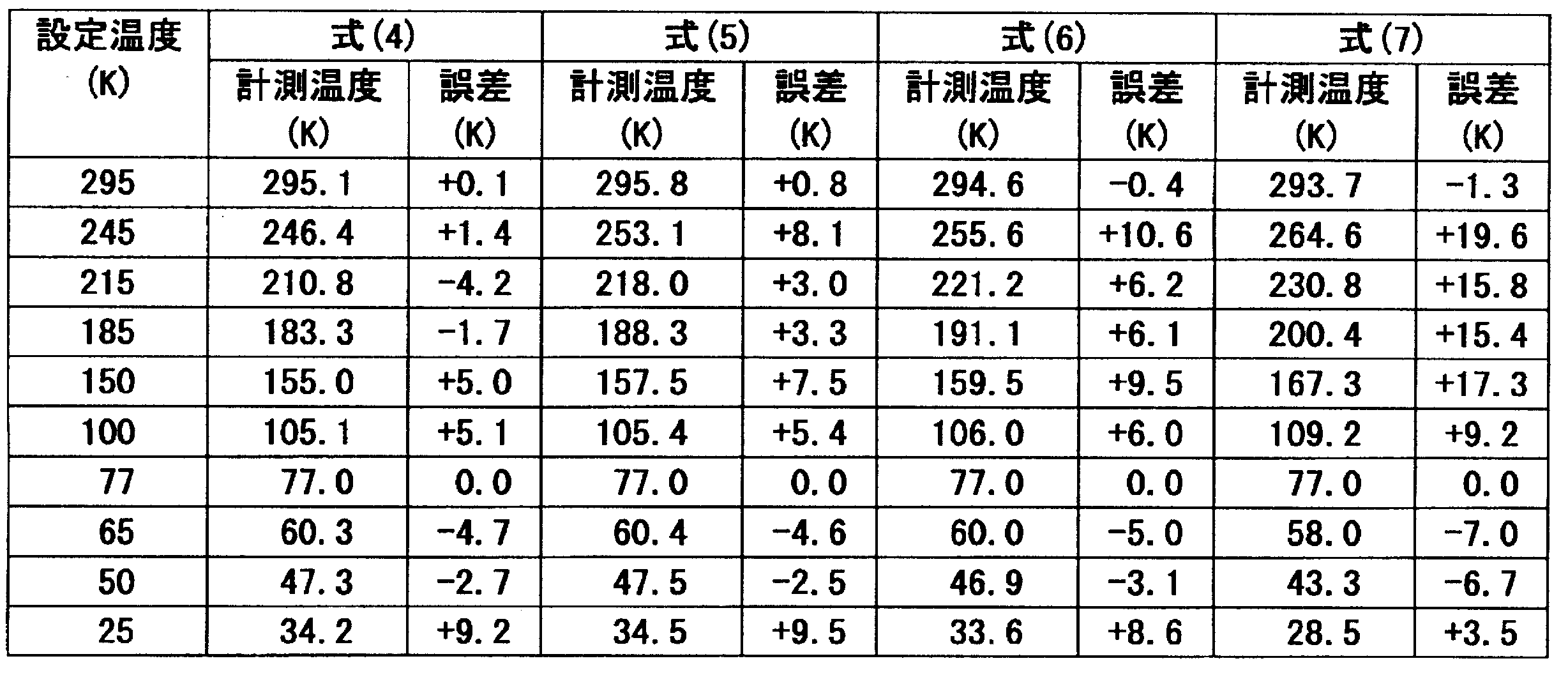
図13は、上記の図9~12の結果をひとつのグラフにプロットした図である。FBG1~4は、温度変化に対するブラッグ波長シフトの関係が非常に近いことを示している。また、この後実施する77Kにおける常電導転移検出では、±20K程度の温度計測精度であると考えられる。上記(温度計測方法の実施例1)の各FBGで得られた近似式より算出する場合に比べて温度精度は劣るが、あらかじめ与えられたひとつの近似式を用いることで、それぞれのFBGに対して絶対温度とブラッグ波長シフトの関係をあらかじめ算出する必要がなくなる点において、この手法は有用である。
(常電導転移の検出方法の実施例1)
次いで、図7Aおよび図7Bに示す試験装置を用いて、本実施例の超電導線材1に対して意図的に常電導転移を発生させ、FBGによる常電導転移の検出と、このとき生じた温度の計測をおこなった。
図14は、超電導線材1を超電導層の臨界温度以下である77Kに冷却保持し、超電導層に160Aの電流を通電した状態でヒータ6に3秒間通電して超電導線材1を局所的に加熱した際の線材温度を各FBG1~4で計測した結果である。
次いで、図7Aおよび図7Bに示す試験装置を用いて、本実施例の超電導線材1に対して意図的に常電導転移を発生させ、FBGによる常電導転移の検出と、このとき生じた温度の計測をおこなった。
図14は、超電導線材1を超電導層の臨界温度以下である77Kに冷却保持し、超電導層に160Aの電流を通電した状態でヒータ6に3秒間通電して超電導線材1を局所的に加熱した際の線材温度を各FBG1~4で計測した結果である。
ヒータ6に近接するFBG4が最も早く発熱を検出し、ヒータ6から遠いFBG1が最も遅く発熱を検出した。なお、本実施例では、ヒータ6に近接するFBG4が発熱を検出した時間を0秒と定義し、ヒータ6から遠いFBG1の発熱を検出して十分に時間が経過した2.1秒の時点で超電導線材1に通電する電流を遮断している。この結果は、ヒータ6で生じた常電導転移が超電導線材1の長手方向に伝播していることを示している。また、各FBGの検出時間差が常電導転移の伝播速度を示し、線材温度変化の傾きが温度上昇速度を示す。
この結果から得られた伝播速度は約25mm/s、温度上昇速度は約80K/sであった。これらの速度から式(8)を用いて常電導転移の起点部、すなわち、ヒータ6の中央で生じた最大温度を求めることができる。なお、式(8)の10mmは、FBG4とヒータ6との距離であり、245Kは、図14に示すFBG4で計測した最高温度である。式(8)の結果が277Kであり、事前に求めた77~295Kにおける温度計測精度が±5Kであることから、線材に生じた最大温度は、約277±5Kであると推定できる。

以上説明したとおり、本実施例によると、常電導転移の伝播速度と超電導線材の温度上昇速度を計測することができる。また、これらの速度から常電導転移の起点部における最大温度、すなわち、この超電導線材に生じた最大温度を計測できる。この最大温度とあらかじめ設定した安全基準温度との比較から、この超電導線材の点検・修理の必要性を判断することができる。
(常電導転移の検出方法の実施例2)
実施例1の構成を用い、ヒータ6に1.5秒間通電した。
図15は、ヒータに1.5秒間通電して超電導線材1を局所的に加熱した際の線材温度をFBGで計測した結果である。なお、本実施例では、FBG4が発熱を検出した時間を0秒と定義し、1.1秒の時点で超電導線材1に通電する電流を遮断している。温度上昇速度は、FBG4では約80K/s、FBG3では約65K/s、FBG2では約40K/s、FBG1では約15K/sであった。
実施例1の構成を用い、ヒータ6に1.5秒間通電した。
図15は、ヒータに1.5秒間通電して超電導線材1を局所的に加熱した際の線材温度をFBGで計測した結果である。なお、本実施例では、FBG4が発熱を検出した時間を0秒と定義し、1.1秒の時点で超電導線材1に通電する電流を遮断している。温度上昇速度は、FBG4では約80K/s、FBG3では約65K/s、FBG2では約40K/s、FBG1では約15K/sであった。
ヒータに近接するFBG4およびFBG3は、実施例1と同じく大きな温度上昇速度を示したことから、FBG4およびFBG3の位置まで常電導転移が伝播したことが分かる。ヒータから遠いFBG2およびFBG1では温度上昇速度がより小さいことから、常電導転移による発熱ではなく、常電導転移したFBG4,3部分からの熱伝導による温度上昇であると断定できる。
この結果より、本実施例において常電導転移を示した範囲は、ヒータ中央からFBG3までの間であり、その距離は約20mmであると推定することができる。なお、この常電導転移が起点から線材長手方向に沿って両方向に等速度で伝播すると考えられるので、実際に常電導転移した範囲は、約40mmであると推定できる。
以上説明したとおり、本実施例によると、常電導転移範囲を検出することができる。従って、仮に超電導線材の点検や修理が必要と判断された場合であっても、その範囲を限定することが可能となり、作業の能率を向上できる。また、実施例1と実施例2を比較すると、いずれかひとつのFBG(FBG4)が発熱を検出した後、早期に超電導線材1に通電する電流を遮断することで、超電導線材に生じる最大温度や常電導転移の範囲を小さくすることができることが分かる。すなわち、温度異常を検知した場合に電流を制限(低下)あるいは遮断(停止)させる等して超電導線材への通電量を制御する制御装置、異常を検知した場合に作業者に警報を発する警報装置、運転状況の表示装置、温度履歴の記録装置などを備えることで、超電導線材の保護装置として利用することができる。
(常電導転移の検出方法の実施例3)
実施例1の構成を用い、超電導線材に通電する電流を変化させた。
図16は、超電導線材に通電する電流を160A、190A、220Aと変化させ、ヒータに1.5秒間通電した際のFBG4で計測した線材温度の経時変化を示すグラフである。図16において、160Aのプロットは、実施例2の結果(図15)を引用した。なお、本実施例では、FBG4が発熱を検出した時間を0秒と定義し、このFBGが150K以上となった時点で超電導線材1に通電する電流を遮断している。温度上昇速度は、160Aでは約80K/s、190Aでは約140K/s、220Aでは約160K/sであった。
実施例1の構成を用い、超電導線材に通電する電流を変化させた。
図16は、超電導線材に通電する電流を160A、190A、220Aと変化させ、ヒータに1.5秒間通電した際のFBG4で計測した線材温度の経時変化を示すグラフである。図16において、160Aのプロットは、実施例2の結果(図15)を引用した。なお、本実施例では、FBG4が発熱を検出した時間を0秒と定義し、このFBGが150K以上となった時点で超電導線材1に通電する電流を遮断している。温度上昇速度は、160Aでは約80K/s、190Aでは約140K/s、220Aでは約160K/sであった。
図17は、超電導線材1に通電した電流の2乗値と温度上昇速度の関係を示すグラフである。温度上昇速度は、超電導線材1に通電した電流の2乗値にほぼ正比例して増加した。常電導転移した超電導線材では、通電した電流(電流値をIとする)が全て金属安定化層(抵抗値をRとする)を流れるとすると、生じるジュール熱はR×I2に正比例する。すなわち、温度上昇速度が超電導線材に通電した電流の2乗値に正比例するのは、常電導転移部の発熱が金属安定化層に生じるジュール熱に起因するためである。
このため、上記(常電導転移の検出方法の実施例2)において常電導転移が伝播したか否かを判定する際には、超電導線材に通電する電流値が大きいほど、常電導転移による温度上昇速度が増大することを考慮する必要がある。
なお、図16では、FBG4上で計測された最高温度は約160~170Kと同程度であるが、上記(常電導転移の検出方法の実施例1)と同様に起点部2での最高温度を推定すると、電流値が高い条件ほど起点部での最高温度が高いという結果が得られる。
このため、上記(常電導転移の検出方法の実施例2)において常電導転移が伝播したか否かを判定する際には、超電導線材に通電する電流値が大きいほど、常電導転移による温度上昇速度が増大することを考慮する必要がある。
なお、図16では、FBG4上で計測された最高温度は約160~170Kと同程度であるが、上記(常電導転移の検出方法の実施例1)と同様に起点部2での最高温度を推定すると、電流値が高い条件ほど起点部での最高温度が高いという結果が得られる。
以上説明したとおり、本実施例によると、超電導線材の常電導転移にともなう発熱のメカニズムを定性的に知ることができ、かつこのときの温度上昇速度や最大温度を定量的に計測することができる。
以上説明した実施例1~3では、超電導線材1をコイル状に固定したが、本発明はこれらの実施例に限定されるものではなく、例えば、超電導線材をケーブル化して大電流を送電する超電導ケーブルにも利用可能である。
(常電導転移の検出方法の実施例4)
実施例1の構成を用い、超電導線材1を50Kに冷却保持し、超電導線材1の外周に設けた電磁石(図示せず)に3Tの磁界を印加した。50K、3Tにおける超電導線材1の臨界電流は約200Aである。本実施例では超電導線材1に通電することにより、電磁力(フープ応力)を発生させることができる。
実施例1の構成を用い、超電導線材1を50Kに冷却保持し、超電導線材1の外周に設けた電磁石(図示せず)に3Tの磁界を印加した。50K、3Tにおける超電導線材1の臨界電流は約200Aである。本実施例では超電導線材1に通電することにより、電磁力(フープ応力)を発生させることができる。
図18は、超電導線材1に通電する電流値を40A、80A、120A、140Aと変化させた際のFBG1~4のブラッグ波長の変化を示すグラフである。フープ応力を発生させると、超電導線材1の長手方向に引張りひずみが生じるので、FBG1~4に前記引張りひずみが伝達される。したがって、FBGの格子間隔Λが伸び、ブラッグ波長λBが長波長側にシフトする。超電導線材1に通電する電流値とブラッグ波長の変化は、FBG1~4で若干差があるものの、超電導線材1に通電する電流値にほぼ正比例することが確認できた。
次いで、一旦超電導線材1に通電する電流を遮断し、一定時間経過した後に再び超電導線材1に100A通電し、フープ応力を発生させた。フープ応力発生後、さらに一定時間経過した後に、ヒータ6に5秒間通電して超電導線材1を局所的に加熱した。図19は、このときの各FBG1~4のブラッグ波長の変化を計測した結果である。また、図20は、図19における-2~12秒の区間を拡大したグラフである。なお、本実施例では、FBG4のブラッグ波長が大きく変化した(発熱を検出した)時間を0秒と定義し、8秒の時点で超電導線材1に通電する電流を遮断している。
図19において、-45秒の時点から超電導線材1に100A通電してフープ応力を発生させることで、縦軸の波長シフトが増大し、FBG1~4のブラッグ波長が長波長側にシフトしているのが確認できる。また、このフープ応力に起因する波長シフトは、FBGが発熱を検出する前(図19では-45秒~約0秒)の区間で略一定であり、しかも、図18における電流100Aに対する波長シフトに相当することが分かる。このフープ応力は電流遮断とともに発生しなくなるので、-45秒から8秒の区間のみ、超電導線材1に生じる温度変化とフープ応力に起因するブラッグ波長シフトを計測していることになる。従って、得られたブラッグ波長シフトをそのまま温度に換算すると、フープ応力によるブラッグ波長シフトも温度変化として換算してしまうため、これをあらかじめ減算して超電導線材1に生じる温度変化を求めることが望ましい。本実施例では、FBG1~4の発熱が明らかに認められない-30秒から-10秒の区間のブラッグ波長変化を個々のFBGについて求め、この値を-45秒から8秒の区間についてのみ減算した。図21は、フープ応力に起因するブラッグ波長シフトを減じたブラッグ波長シフトを示す結果である。これにより、フープ応力によるブラッグ波長シフトを温度変化として換算することなく、超電導線材1に生じる温度変化を正確に求めることができる。
次いで、図21で得られたブラッグ波長シフトをもとに超電導線材1の温度を求める。実施例1であらかじめ得られた絶対温度とブラッグ波長シフトの関係から、50Kからの波長シフトと絶対温度の関係を求め、これを4次関数近似した結果とこの近似式の相関関数(R2)を式(9)~(12)に示す。なお、式(9)~式(12)における単位は、絶対温度(y)がK、波長シフト(x)がnmである。




以上得られた数式(9)~(12)を用い、図21で得られたブラッグ波長シフトを超電導線材1の温度に換算した。図22は、超電導線材1の温度に換算した結果を示すグラフである。フープ応力によるブラッグ波長シフトを温度として換算することなく、超電導線材1に生じる温度変化を正確に求めることができた。この結果から得られた伝播速度は約11mm/s、温度上昇速度は約25K/sであった。これらの速度とFBG4で計測した最高温度256Kを上記一般式(L/V)υ+Tmaxに代入して式(8)と同様に計算すると、式(13)に示すように、超電導線材1に生じた最大温度は284Kと推定された。

本実施例では、超電導線材1の外周に設けた電磁石により電磁力(フープ応力)を発生させたが、長尺の超電導線材を用いて大型コイルを作製し、これに電流を通電することでフープ応力を発生させる場合においても本発明は利用可能である。
1 超電導線材
1a 基材
1b 超電導層
1c 金属安定化層
2 常電導転移の起点部
3 光ファイバ
4 ファイバブラッググレーティング(FBG)
5 接着層
10 温度計測器
11 広帯域光源
12 光部品
13 分光素子
14 受光素子
1a 基材
1b 超電導層
1c 金属安定化層
2 常電導転移の起点部
3 光ファイバ
4 ファイバブラッググレーティング(FBG)
5 接着層
10 温度計測器
11 広帯域光源
12 光部品
13 分光素子
14 受光素子
Claims (10)
- 基材と、77K以上の臨界温度を有する超電導層と、金属安定化層とを備える超電導線材の常電導転移の検出方法であって、
コアにその長手方向に沿って複数のファイバブラッググレーティングが形成された光ファイバを前記超電導線材に接着固定し;
前記超電導線材の温度変化に対する前記ファイバブラッググレーティングのブラッグ波長の変化をあらかじめ測定し、前記ブラッグ波長の変化から前記超電導線材の温度を計測するための関係式を求め;
前記超電導線材に常電導転移が生じる前後の前記複数のファイバブラッググレーティングの温度変化を、前記関係式により求め;
前記複数のファイバブラッググレーティングの温度上昇が開始した時間差と、前記複数のファイバブラッググレーティングの間隔とに基づいて、前記常電導転移の伝播速度を算出する;
ことを特徴とする超電導線材の常電導転移の検出方法。 - 前記複数のファイバブラッググレーティングのいずれかにおいて計測した最高温度をTmax、このファイバブラッググレーティングから前記常電導転移の起点部までの距離をL、このファイバブラッググレーティングにおける温度上昇速度をυ、前記常電導転移の伝播速度をVとして、前記常電導転移の起点部における最高温度を、(L/V)υ+Tmaxにより算出することを特徴とする請求項1に記載の超電導線材の常電導転移の検出方法。
- 前記最高温度Tmaxおよび前記温度上昇速度υを、前記常電導転移の起点部に最も近いファイバブラッググレーティングを用いて計測することを特徴とする請求項2に記載の超電導線材の常電導転移の検出方法。
- 前記複数のファイバブラッググレーティングのそれぞれにおける温度上昇速度を、各ファイバブラッググレーティングの温度変化から求め、前記温度上昇速度が所定のしきい値以上であることにより、このファイバブラッググレーティングの位置に前記常電導転移が伝播したことを確認することを特徴とする請求項1~3のいずれか1項に記載の超電導線材の常電導転移の検出方法。
- 前記所定のしきい値は、前記超電導線材に通電する電流値ごとにあらかじめ設定されることを特徴とする請求項4に記載の超電導線材の常電導転移の検出方法。
- 基材と、77K以上の臨界温度を有する超電導層と、金属安定化層とを備える超電導線材の常電導転移の検出方法であって、
コアにその長手方向に沿って複数のファイバブラッググレーティングが形成された光ファイバを前記超電導線材に接着固定し;
前記超電導線材の温度変化に対する前記ファイバブラッググレーティングのブラッグ波長の変化をあらかじめ測定し、前記ブラッグ波長の変化から前記超電導線材の温度を計測するための関係式を求め;
前記超電導線材に常電導転移が生じる前後の前記複数のファイバブラッググレーティングの温度変化を、前記関係式により求め;
前記複数のファイバブラッググレーティングのそれぞれにおける温度上昇速度を、各ファイバブラッググレーティングの温度変化から求め;
前記温度上昇速度が所定のしきい値以上であるか否かにより、このファイバブラッググレーティングの位置に前記常電導転移が伝播したか否かを判定する;
ことを特徴とする超電導線材の常電導転移の検出方法。 - 前記常電導転移が伝播したと判定されたファイバブラッググレーティングのうち、前記常電導転移の起点部から最も遠いファイバブラッググレーティングまでの距離を2倍することにより、前記常電導転移が生じた範囲を推定することを特徴とする請求項6に記載の超電導線材の常電導転移の検出方法。
- 前記所定のしきい値は、前記超電導線材に通電する電流値ごとにあらかじめ設定されることを特徴とする請求項6または7に記載の超電導線材の常電導転移の検出方法。
- 前記超電導線材がコイル状であり、このコイルにより発生させる電磁力によるファイバブラッググレーティングのブラッグ波長の変化をあらかじめ測定し、
前記電磁力によるファイバブラッググレーティングのブラッグ波長の変化を減算して得られるブラッグ波長の変化を前記関係式に適用して、前記超電導線材に常電導転移が生じる前後の前記複数のファイバブラッググレーティングの温度変化を求める請求項1~8のいずれか1項に記載の超電導線材の常電導転移の検出方法。 - 前記複数のファイバブラッググレーティングが形成された光ファイバは、広帯域光源と、分光素子と、前記広帯域光源からの測定光が入射されるとともに、前記複数のファイバブラッググレーティングからのブラッグ反射光を前記分光素子に入射する光部品と、前記分光素子により分光された光を受光して電圧信号を出力する受光素子とを備える温度計測器に接続されている請求項1~9のいずれか1項に記載の超電導線材の常電導転移の検出方法。
Priority Applications (4)
| Application Number | Priority Date | Filing Date | Title |
|---|---|---|---|
| JP2012522487A JP5393888B2 (ja) | 2010-06-28 | 2011-04-06 | 超電導線材の常電導転移の検出方法 |
| CN201180005090.8A CN102667456B (zh) | 2010-06-28 | 2011-04-06 | 超导线材的常导转变的检测方法 |
| EP11800486.0A EP2587254B1 (en) | 2010-06-28 | 2011-04-06 | Method for detecting transition to normal state of a superconducting wire material |
| US13/728,570 US9488606B2 (en) | 2010-06-28 | 2012-12-27 | Method for detecting non-superconducting transition of superconducting wire |
Applications Claiming Priority (4)
| Application Number | Priority Date | Filing Date | Title |
|---|---|---|---|
| JP2010146304 | 2010-06-28 | ||
| JP2010-146304 | 2010-06-28 | ||
| JP2011057939 | 2011-03-16 | ||
| JP2011-057939 | 2011-03-16 |
Related Child Applications (1)
| Application Number | Title | Priority Date | Filing Date |
|---|---|---|---|
| US13/728,570 Continuation US9488606B2 (en) | 2010-06-28 | 2012-12-27 | Method for detecting non-superconducting transition of superconducting wire |
Publications (1)
| Publication Number | Publication Date |
|---|---|
| WO2012002016A1 true WO2012002016A1 (ja) | 2012-01-05 |
Family
ID=45401753
Family Applications (1)
| Application Number | Title | Priority Date | Filing Date |
|---|---|---|---|
| PCT/JP2011/058700 Ceased WO2012002016A1 (ja) | 2010-06-28 | 2011-04-06 | 超電導線材の常電導転移の検出方法 |
Country Status (5)
| Country | Link |
|---|---|
| US (1) | US9488606B2 (ja) |
| EP (1) | EP2587254B1 (ja) |
| JP (1) | JP5393888B2 (ja) |
| CN (1) | CN102667456B (ja) |
| WO (1) | WO2012002016A1 (ja) |
Cited By (3)
| Publication number | Priority date | Publication date | Assignee | Title |
|---|---|---|---|---|
| RU2637398C2 (ru) * | 2012-11-15 | 2017-12-04 | Конинклейке Филипс Н.В. | Мрт с участием распределенного датчика для контроля температуры и/или деформации кабелей катушки и фильтров |
| RU2642125C2 (ru) * | 2012-12-18 | 2018-01-24 | Конинклейке Филипс Н.В. | Многократно используемый температурный датчик, безопасный при проведении магнитно-резонансной томографии, для измерения температуры поверхности и тела |
| CN109682853A (zh) * | 2019-01-09 | 2019-04-26 | 南京大学 | 一种基于fbg的冻土含冰量分布式原位测量方法及装置 |
Families Citing this family (18)
| Publication number | Priority date | Publication date | Assignee | Title |
|---|---|---|---|---|
| CN104157366B (zh) * | 2014-07-31 | 2017-08-08 | 上海超导科技股份有限公司 | 内封测量光纤的超导带材及其制备方法、装置 |
| CN104390721A (zh) * | 2014-11-24 | 2015-03-04 | 南京信息工程大学 | 温度传感器、温度测量方法及装置 |
| CN104614641A (zh) * | 2015-01-09 | 2015-05-13 | 山东航天电子技术研究所 | 一种准分布式光纤光栅导线故障定位系统与方法 |
| US20200123052A1 (en) * | 2016-01-08 | 2020-04-23 | North Carolina State University | Enhanced optical fibers for low temperature sensing |
| JP6328683B2 (ja) * | 2016-04-12 | 2018-05-23 | ファナック株式会社 | 小型チラーが使用可能なレーザ装置 |
| CN105997016B (zh) * | 2016-06-14 | 2018-11-02 | 广州视源电子科技股份有限公司 | 基于电子体温计识别测量对象的方法及其系统 |
| WO2019027964A1 (en) * | 2017-07-31 | 2019-02-07 | North Carolina State University | SELF-MONITORING SUPERCONDUCTING CABLES HAVING INTEGRATED OPTICAL FIBERS |
| DE102017119810B4 (de) * | 2017-08-29 | 2019-05-09 | fos4X GmbH | Optoelektrischer Chip |
| US11879789B2 (en) * | 2019-07-02 | 2024-01-23 | International Business Machines Corporation | On-chip thermometer for superconducting quantum computing devices |
| US11674854B2 (en) | 2019-07-02 | 2023-06-13 | International Business Machines Corporation | Mapping temperature distribution in superconducting devices |
| US12070753B2 (en) * | 2020-03-30 | 2024-08-27 | Fei Company | Method for temperature monitoring in cryo-electron microscopy |
| GB202007785D0 (en) * | 2020-05-26 | 2020-07-08 | Royal Holloway & Bedford New College | Current sensing noise thermometer |
| CN111665462B (zh) * | 2020-06-08 | 2024-06-04 | 华中科技大学 | 一种高温超导磁体失超检测装置及方法 |
| CN112098776B (zh) * | 2020-09-18 | 2022-11-08 | 国网江苏省电力有限公司无锡供电分公司 | 一种覆冰及污闪电流监测系统及方法 |
| EP4381259A1 (en) * | 2021-08-06 | 2024-06-12 | Massachusetts Institute Of Technology | Fiber optic quench detection |
| CN115773770A (zh) * | 2022-11-03 | 2023-03-10 | 先进能源科学与技术广东省实验室 | 一种分布式光纤传感器、应用及制作方法 |
| WO2024186379A2 (en) * | 2022-12-28 | 2024-09-12 | The Penn State Research Foundation | Dynamic management of superconducting magnets |
| WO2024173669A1 (en) * | 2023-02-16 | 2024-08-22 | Commonwealth Fusion Systems Llc | Dense linear ramp bragg grating pattern for quench detection in high temperature superconducting magnets |
Citations (4)
| Publication number | Priority date | Publication date | Assignee | Title |
|---|---|---|---|---|
| JPH07170721A (ja) | 1992-06-26 | 1995-07-04 | Canon Inc | 超伝導モーター、超伝導マグネット装置、超伝導アクチュエーター、超伝導線のクエンチ検出方法及び超伝導線 |
| JPH08304271A (ja) | 1995-05-11 | 1996-11-22 | Canon Inc | 超伝導体クエンチ検出装置及び検出方法 |
| JP2577682B2 (ja) | 1992-04-20 | 1997-02-05 | 株式会社日立製作所 | 超電導体の温度測定方法及び装置並びに超電導マグネットのクエンチ予知方法及び装置 |
| US6072922A (en) | 1998-06-19 | 2000-06-06 | Science And Engineering Applications Company, Inc. | Cryogenic fiber optic temperature sensor |
Family Cites Families (7)
| Publication number | Priority date | Publication date | Assignee | Title |
|---|---|---|---|---|
| US5065087A (en) * | 1988-10-04 | 1991-11-12 | Sharp Kabushiki Kaisha | Apparatus for observing a superconductive phenomenon in a superconductor |
| JPH11162269A (ja) * | 1997-11-27 | 1999-06-18 | Toshiba Corp | 超電導機器 |
| JP3519333B2 (ja) * | 2000-02-10 | 2004-04-12 | エヌ・ティ・ティ・アドバンステクノロジ株式会社 | 光ファイバセンサ |
| DE102006025700B4 (de) * | 2006-06-01 | 2009-04-16 | Siemens Ag | Optische Messeinrichtung zur Temperaturbestimmung in einer kryogenen Umgebung und temperaturüberwachbare Wickelanordnung |
| CN1963477B (zh) * | 2006-11-08 | 2011-03-30 | 中国科学院电工研究所 | 一种非接触连续测量超导线/带材n指数均匀性的方法和装置 |
| CN101126787B (zh) * | 2007-09-28 | 2010-06-09 | 中国科学院电工研究所 | 一种超导线圈失超检测方法 |
| CN102305804B (zh) * | 2011-05-19 | 2013-06-05 | 北京鼎臣超导科技有限公司 | 一种高温超导材料超导转变温度测量装置及测量方法 |
-
2011
- 2011-04-06 WO PCT/JP2011/058700 patent/WO2012002016A1/ja not_active Ceased
- 2011-04-06 EP EP11800486.0A patent/EP2587254B1/en not_active Not-in-force
- 2011-04-06 CN CN201180005090.8A patent/CN102667456B/zh not_active Expired - Fee Related
- 2011-04-06 JP JP2012522487A patent/JP5393888B2/ja not_active Expired - Fee Related
-
2012
- 2012-12-27 US US13/728,570 patent/US9488606B2/en active Active
Patent Citations (4)
| Publication number | Priority date | Publication date | Assignee | Title |
|---|---|---|---|---|
| JP2577682B2 (ja) | 1992-04-20 | 1997-02-05 | 株式会社日立製作所 | 超電導体の温度測定方法及び装置並びに超電導マグネットのクエンチ予知方法及び装置 |
| JPH07170721A (ja) | 1992-06-26 | 1995-07-04 | Canon Inc | 超伝導モーター、超伝導マグネット装置、超伝導アクチュエーター、超伝導線のクエンチ検出方法及び超伝導線 |
| JPH08304271A (ja) | 1995-05-11 | 1996-11-22 | Canon Inc | 超伝導体クエンチ検出装置及び検出方法 |
| US6072922A (en) | 1998-06-19 | 2000-06-06 | Science And Engineering Applications Company, Inc. | Cryogenic fiber optic temperature sensor |
Non-Patent Citations (3)
| Title |
|---|
| See also references of EP2587254A4 |
| WOLFGANG ECKE ET AL.: "Fiber optical grating sensors for structural health monitoring at cryogenic temperatures", PROCEEDINGS OF SPIE, vol. 6530, 2007, pages 653002, XP002741377 |
| WOLFGANG ECKE ET AL.: "Fiber-optic Bragg grating sensors for structural health monitoring at cryogenic temperatures", PROCEEDINGS OF SPIE, vol. 6530, 2007, pages 1 - 10, XP055074586 * |
Cited By (4)
| Publication number | Priority date | Publication date | Assignee | Title |
|---|---|---|---|---|
| RU2637398C2 (ru) * | 2012-11-15 | 2017-12-04 | Конинклейке Филипс Н.В. | Мрт с участием распределенного датчика для контроля температуры и/или деформации кабелей катушки и фильтров |
| RU2642125C2 (ru) * | 2012-12-18 | 2018-01-24 | Конинклейке Филипс Н.В. | Многократно используемый температурный датчик, безопасный при проведении магнитно-резонансной томографии, для измерения температуры поверхности и тела |
| CN109682853A (zh) * | 2019-01-09 | 2019-04-26 | 南京大学 | 一种基于fbg的冻土含冰量分布式原位测量方法及装置 |
| CN109682853B (zh) * | 2019-01-09 | 2024-02-13 | 南京大学 | 一种基于fbg的冻土含冰量分布式原位测量方法及装置 |
Also Published As
| Publication number | Publication date |
|---|---|
| US9488606B2 (en) | 2016-11-08 |
| JP5393888B2 (ja) | 2014-01-22 |
| JPWO2012002016A1 (ja) | 2013-08-22 |
| CN102667456B (zh) | 2014-06-25 |
| EP2587254A1 (en) | 2013-05-01 |
| EP2587254B1 (en) | 2017-11-29 |
| CN102667456A (zh) | 2012-09-12 |
| US20160047763A1 (en) | 2016-02-18 |
| EP2587254A4 (en) | 2015-08-05 |
Similar Documents
| Publication | Publication Date | Title |
|---|---|---|
| JP5393888B2 (ja) | 超電導線材の常電導転移の検出方法 | |
| US20140268130A1 (en) | Method for detecting non-superconducting transition of superconducting wire | |
| US6876785B1 (en) | Embedded sensor, method for producing, and temperature/strain fiber optic sensing system | |
| Rai | Temperature sensors and optical sensors | |
| Wanser | Fundamental phase noise limit in optical fibres due to temperature fluctuations | |
| Chiuchiolo et al. | Cryogenic-temperature profiling of high-power superconducting lines using local and distributed optical-fiber sensors | |
| Li et al. | Shape deposition manufacturing of smart metallic structures with embedded sensors | |
| JP5645713B2 (ja) | 超電導コイル装置、及び超電導コイルの常電導転移の検出方法 | |
| KR970007812B1 (ko) | 복굴절 온도센서 | |
| Dedyulin et al. | Packaging and precision testing of fiber-Bragg-grating and silicon ring-resonator thermometers: current status and challenges | |
| JP2006047154A (ja) | 光ファイバ温度センサ及びその製造方法 | |
| DeMiguel-Soto et al. | Interferometric vs wavelength selective optical fiber sensors for cryogenic temperature measurements | |
| Soman et al. | Design of cryogenic temperature sensors using copper-coated fiber Bragg gratings | |
| EP4022689B1 (en) | Hotspot monitoring system for superconducting device | |
| Kajanto et al. | A silicon-based fibre-optic temperature sensor | |
| WO2017091073A1 (en) | Cryogenic fiber optic sensor device | |
| RU2813237C1 (ru) | Волоконно-оптический датчик температуры на основе термооптического эффекта кремния | |
| CN223992647U (zh) | 一种fbg与直接带隙半导体混合式光纤温度传感器 | |
| KR102462081B1 (ko) | 광섬유 프로브 방식의 온도센서를 이용한 전기설비의 온도 열화 모니터링 시스템 | |
| JP5977698B2 (ja) | 光ファイバ温度センサ | |
| Beheim et al. | Laser-annealed thin-film fiber-optic temperature sensor | |
| Lord et al. | Remote measurement of temperature in the presence of a strong magnetic field | |
| Freitas | Optical fiber temperature sensors for cryogenic applications | |
| de Lima Junior et al. | A fiber optical thermometer for high power transformer monitoring utilizing the thermo-optical phase transition of VO2 | |
| Grattan et al. | Optical-fiber sensors: Temperature and pressure sensors |
Legal Events
| Date | Code | Title | Description |
|---|---|---|---|
| 121 | Ep: the epo has been informed by wipo that ep was designated in this application |
Ref document number: 11800486 Country of ref document: EP Kind code of ref document: A1 |
|
| WWE | Wipo information: entry into national phase |
Ref document number: 2012522487 Country of ref document: JP |
|
| NENP | Non-entry into the national phase |
Ref country code: DE |
|
| REEP | Request for entry into the european phase |
Ref document number: 2011800486 Country of ref document: EP |
|
| WWE | Wipo information: entry into national phase |
Ref document number: 2011800486 Country of ref document: EP |