WO2012002016A1 - Procédé de détection du passage au courant normal d'une bobine supraconductrice - Google Patents
Procédé de détection du passage au courant normal d'une bobine supraconductrice Download PDFInfo
- Publication number
- WO2012002016A1 WO2012002016A1 PCT/JP2011/058700 JP2011058700W WO2012002016A1 WO 2012002016 A1 WO2012002016 A1 WO 2012002016A1 JP 2011058700 W JP2011058700 W JP 2011058700W WO 2012002016 A1 WO2012002016 A1 WO 2012002016A1
- Authority
- WO
- WIPO (PCT)
- Prior art keywords
- superconducting wire
- temperature
- transition
- fiber bragg
- change
- Prior art date
- Legal status (The legal status is an assumption and is not a legal conclusion. Google has not performed a legal analysis and makes no representation as to the accuracy of the status listed.)
- Ceased
Links
Images










Classifications
-
- G—PHYSICS
- G01—MEASURING; TESTING
- G01N—INVESTIGATING OR ANALYSING MATERIALS BY DETERMINING THEIR CHEMICAL OR PHYSICAL PROPERTIES
- G01N25/00—Investigating or analyzing materials by the use of thermal means
-
- G—PHYSICS
- G01—MEASURING; TESTING
- G01K—MEASURING TEMPERATURE; MEASURING QUANTITY OF HEAT; THERMALLY-SENSITIVE ELEMENTS NOT OTHERWISE PROVIDED FOR
- G01K1/00—Details of thermometers not specially adapted for particular types of thermometer
- G01K1/14—Supports; Fastening devices; Arrangements for mounting thermometers in particular locations
-
- G—PHYSICS
- G01—MEASURING; TESTING
- G01K—MEASURING TEMPERATURE; MEASURING QUANTITY OF HEAT; THERMALLY-SENSITIVE ELEMENTS NOT OTHERWISE PROVIDED FOR
- G01K11/00—Measuring temperature based upon physical or chemical changes not covered by groups G01K3/00, G01K5/00, G01K7/00 or G01K9/00
- G01K11/32—Measuring temperature based upon physical or chemical changes not covered by groups G01K3/00, G01K5/00, G01K7/00 or G01K9/00 using changes in transmittance, scattering or luminescence in optical fibres
- G01K11/3206—Measuring temperature based upon physical or chemical changes not covered by groups G01K3/00, G01K5/00, G01K7/00 or G01K9/00 using changes in transmittance, scattering or luminescence in optical fibres at discrete locations in the fibre, e.g. using Bragg scattering
-
- G—PHYSICS
- G01—MEASURING; TESTING
- G01K—MEASURING TEMPERATURE; MEASURING QUANTITY OF HEAT; THERMALLY-SENSITIVE ELEMENTS NOT OTHERWISE PROVIDED FOR
- G01K13/00—Thermometers specially adapted for specific purposes
- G01K13/006—Thermometers specially adapted for specific purposes for cryogenic purposes
-
- G—PHYSICS
- G01—MEASURING; TESTING
- G01K—MEASURING TEMPERATURE; MEASURING QUANTITY OF HEAT; THERMALLY-SENSITIVE ELEMENTS NOT OTHERWISE PROVIDED FOR
- G01K3/00—Thermometers giving results other than momentary value of temperature
- G01K3/005—Circuits arrangements for indicating a predetermined temperature
-
- G—PHYSICS
- G01—MEASURING; TESTING
- G01K—MEASURING TEMPERATURE; MEASURING QUANTITY OF HEAT; THERMALLY-SENSITIVE ELEMENTS NOT OTHERWISE PROVIDED FOR
- G01K2203/00—Application of thermometers in cryogenics
Definitions
- the present invention relates to a method for detecting a normal conducting transition of a superconducting wire.
- This application claims priority based on Japanese Patent Application No. 2011-057939 filed in Japan on March 16, 2011 and Japanese Patent Application No. 2010-146304 filed in Japan on June 28, 2010. , The contents of which are incorporated herein.
- Superconducting wire is expected to be applied to superconducting magnets and superconducting cables, such as nuclear magnetic resonance imaging devices, magnetic levitation railways, magnetic bearings, and motors. There is a lot of research to ensure sex.
- Superconductors that make up superconducting wires generally have a critical temperature (the upper limit temperature indicating superconductivity) that is lower than room temperature, so they can be cooled to below the critical temperature using a cooling medium such as liquid helium or liquid nitrogen or a refrigerator. Used. However, even if the superconducting wire is cooled below the critical temperature from the outside, if a normal conduction transition occurs that causes a transition from the superconducting state to the normal conducting state due to thermal disturbance in a part of the superconducting wire during energization, Joule There is a problem (quenching phenomenon) that heat is generated and the temperature of the superconducting wire rises, the normal conducting transition around it is promoted, and the region of the normal conducting state is expanded.
- a critical temperature the upper limit temperature indicating superconductivity
- Patent Literature 1 a carbon film is provided on the superconductor to detect a slight temperature rise just before quenching, when the superconductor has transitioned to a normal conducting state due to thermal disturbance or the like, and a minute temperature change is caused from the voltage of the carbon film.
- a method of detecting is described.
- the method described in Patent Document 1 has a property that the electrical resistance value with respect to the temperature of the carbon film is remarkably large in an extremely low temperature region of about several K (Kelvin) from the temperature of liquid helium (see FIG. 7 of Patent Document 1). It is what you use. For this reason, it is difficult to apply to a high temperature superconductor having a critical temperature of 77K or higher (for example, about 100K).
- Patent Document 2 discloses a superconductor quench in which polarized light from a light source is incident on an optical fiber wound around a superconducting wire, a phase difference of polarization from the optical fiber is detected, and an abnormal polarization state of light transmitted through the optical fiber is detected.
- a detection method is described.
- Patent Document 3 (particularly, the fourth invention thereof), an optical fiber is attached to the outside of the superconducting wire, and the reflected light from the deformed portion of the optical fiber due to mechanical displacement of the abnormal portion in the superconducting wire during energization or the optical fiber
- a quench detection method for a superconducting wire is described in which transmitted light from the other end is measured to detect abnormality of the superconducting wire.
- the methods described in Patent Documents 2 and 3 can only determine whether there is an abnormality in the optical fiber by causing the superconducting wire to move due to quenching and increasing the displacement and deformation of the optical fiber. The details of temperature change cannot be measured.
- Patent Document 4 and Non-Patent Document 1 describe a temperature measurement method at an extremely low temperature by an optical fiber type temperature sensor using a fiber Bragg grating (FBG).
- FBG is an optical fiber type device in which a periodic refractive index change (grating) is formed in the core of an optical fiber, and selectively reflects a specific wavelength (Bragg wavelength) determined by the refractive index of the core and the period of the grating.
- a coating material (coating) such as aluminum (Al) or polymethyl methacrylate (PMMA) having a larger thermal expansion coefficient (TEC) than silica, which is the main component of the optical fiber, is provided around the FBG of the optical fiber.
- TEC thermal expansion coefficient
- Non-Patent Document 1 shows a measurement example of strain, temperature, and linear expansion.
- Japanese Patent No. 2577682 Japanese Unexamined Patent Publication No. 8-304271 Japanese Unexamined Patent Publication No. 7-170721 US Pat. No. 6,072,922
- Patent Document 4 and Non-Patent Document 1 an FBG provided with a coating material is used, for example, as shown in FIG. It is only described that the temperature of the medium can be measured when the FBG provided with the coating material is immersed in a homogeneous medium as shown in FIG. Moreover, when using FBG described in patent document 4 for the temperature measurement of a high-temperature superconductor, since the high-temperature superconductor formed into the wire is poorly deformable, the superconducting wire cannot be disposed around the entire periphery of the coating material. . That is, the medium around the FBG provided with the covering material cannot be made homogeneous.
- the coating material has a difference between the thermal expansion coefficient of the coating material and the superconducting wire. Expansion and contraction is restricted. For this reason, there is a possibility of adversely affecting temperature measurement accuracy and response speed.
- the present invention has been made in view of the above circumstances, and detects a temperature change associated with a normal conduction transition with good accuracy and responsiveness, and a superconducting wire in which the normal conduction transition occurs based on the temperature change of the superconducting wire. It is an object of the present invention to provide a method for detecting a normal conduction transition of a superconducting wire capable of more accurately detecting the state of the above.
- the method for detecting a normal conduction transition of a superconducting wire is a method for detecting a normal conduction transition of a superconducting wire comprising a base material, a superconducting layer having a critical temperature of 77 K or higher, and a metal stabilizing layer.
- An optical fiber having a plurality of fiber Bragg gratings formed in a core along a longitudinal direction of the core is bonded and fixed to the superconducting wire; a change in Bragg wavelength of the fiber Bragg grating with respect to a temperature change of the superconducting wire.
- Tmax is the maximum temperature measured in any of the plurality of fiber Bragg gratings, and the origin of the normal conduction transition from the fiber Bragg grating.
- the maximum temperature at the starting point of the normal conduction transition is calculated by (L / V) ⁇ + Tmax, where L is the distance to the part, ⁇ is the temperature rise rate in the fiber Bragg grating, and V is the propagation speed of the normal conduction transition. May be.
- the maximum temperature Tmax and the temperature rise rate ⁇ are determined using a fiber Bragg grating closest to the starting point of the normal conduction transition. You may measure.
- a temperature rise rate in each of the plurality of fiber Bragg gratings is obtained from a temperature change of each fiber Bragg grating, and the temperature rise rate is obtained. May be confirmed that the normal conduction transition has propagated to the position of the fiber Bragg grating.
- the predetermined threshold value may be set in advance for each current value to be passed through the superconducting wire.
- the method for detecting a normal conduction transition of a superconducting wire is a method for detecting a normal conduction transition of a superconducting wire comprising a base material, a superconducting layer having a critical temperature of 77K or higher, and a metal stabilizing layer.
- An optical fiber having a plurality of fiber Bragg gratings formed in a core along a longitudinal direction of the core is bonded and fixed to the superconducting wire; a change in Bragg wavelength of the fiber Bragg grating with respect to a temperature change of the superconducting wire.
- the temperature rise rate in each of the plurality of fiber Bragg gratings is calculated for each fiber. Calculated from the temperature change of the Bragg grating; checked by whether the temperature increase rate is above a predetermined threshold, whether the normal conductive transition is propagated to the position of the fiber Bragg grating.
- the range where the normal conduction transition has occurred may be estimated by doubling the distance to the Bragg grating.
- the predetermined threshold value may be set in advance for each current value to be passed through the superconducting wire.
- the superconducting wire is coiled, and a change in the Bragg wavelength of the fiber Bragg grating due to electromagnetic force generated by the coil is measured in advance. And applying the Bragg wavelength change obtained by subtracting the Bragg wavelength change of the fiber Bragg grating due to the electromagnetic force to the relational expression, so that the plurality of fiber Bragg gratings before and after the normal conduction transition occurs in the superconducting wire The temperature change may be obtained.
- the optical fiber in which the plurality of fiber Bragg gratings are formed includes a broadband light source, a spectroscopic element, measurement light from the broadband light source being incident on the optical fiber, and Bragg reflected light from the plurality of fiber Bragg gratings. May be connected to a temperature measuring device that includes an optical component that enters the spectral element and a light receiving element that receives light dispersed by the spectral element and outputs a voltage signal.
- the change in the Bragg wavelength of the FBG with respect to the temperature change of the superconducting wire is measured in advance, and the temperature of the superconducting wire is measured from the change in the Bragg wavelength.
- the distance from the FBG to the starting point of the normal conducting transition, the temperature rise rate in the FBG, and the propagation speed of the normal conducting transition, the starting point of the normal conducting transition It is also possible to determine the maximum temperature at.
- the normal conduction transition propagates to the position of the FBG, it is also possible to determine whether the normal conduction transition has propagated from the temperature rise speed of the FBG by utilizing the fact that the temperature rise speed becomes larger than the case where it does not. Is possible.
- the FBGs that have been determined to have propagated the normal conduction transition it is also possible to estimate the range in which the normal conduction transition has occurred based on the distance from the starting point of the normal conduction transition to the farthest FBG.
- the temperature change occurring in the superconducting wire can be determined more accurately.
- AOTF spectroscopic element
- 10 is a graph in which a wavelength shift due to a temperature change is obtained by subtracting a wavelength shift due to electromagnetic force from a wavelength shift of each FBG in a section of ⁇ 2 to 12 seconds in Example 4 of the detection method of the normal conducting transition.
- FIG. 3 shows an example of the temperature measuring instrument 10 using the optical fiber 3 in which a plurality of fiber Bragg gratings 4 are formed.
- FIG. 4 shows an example of a state in which the optical fiber 3 is bonded and fixed on the metal stabilizing layer 1 c of the superconducting wire 1.
- the superconducting wire 1 includes at least a substrate 1a, a superconducting layer 1b having a critical temperature of 77K or higher, and a metal stabilizing layer 1c.
- the base material 1a applicable to the superconducting wire 1 of this embodiment can be used as a base material for a normal superconducting wire, and may be high strength.
- Examples thereof include various metal materials such as silver, platinum, stainless steel, copper, nickel alloy such as Hastelloy (registered trademark), or a base material in which ceramics are arranged on these various metal materials.
- nickel alloys are preferable.
- Hastelloy trade name made by US Haynes Co., Ltd.
- the thickness of the substrate 1a may be appropriately adjusted according to the purpose, and is usually 10 to 500 ⁇ m.
- the superconductor constituting the superconducting layer 1b may be a known superconductor as long as it has a critical temperature of 77 K or higher.
- REBa 2 Cu 3 O y RE is Y, La, Nd, Sm, And a superconductor having a composition represented by a rare earth element such as Er or Gd.
- Examples of the superconducting layer include Y123 (YBa 2 Cu 3 O 7-X ) or Gd123 (GdBa 2 Cu 3 O 7-X ).
- oxide superconductors for example, Bi 2 Sr 2 Ca n- 1 Cu n O 4 + 2n + in ⁇ a composition or the like may be used superconductor consisting of high other oxide superconductors having a critical temperature represented.
- the thickness of the superconducting layer 1b is not particularly limited, but is preferably about 0.5 to 5 ⁇ m and preferably has a uniform thickness.
- the superconducting layer 1b is formed by sputtering, vacuum deposition, laser deposition, electron beam deposition, pulse laser deposition (PLD), ion beam assisted deposition (IBAD), chemical vapor deposition (CVD), etc.
- PLD pulse laser deposition
- IBAD ion beam assisted deposition
- CVD chemical vapor deposition
- MOD method thermal coating decomposition method
- This is a method for forming a thin film on a substrate, and does not require a vacuum process, and is capable of high-speed film formation at a low cost. Therefore, it is suitable for manufacturing a long tape-shaped superconducting conductor.
- the metal stabilization layer 1c laminated on the superconducting layer 1b is made of a highly conductive metal material.
- the metal material constituting the metal stabilizing layer 1c is not particularly limited as long as it is a material having good conductivity, but is relatively inexpensive such as copper alloy such as copper and brass (Cu—Zn alloy), stainless steel and the like. It is preferable to use copper, and copper is more preferable because it has high conductivity and is inexpensive.
- the thickness of the metal stabilizing layer 1c is preferably 10 to 300 ⁇ m.
- the metal stabilization layer 1c can be formed by a known method, for example, a sputtering method or a method of soldering a metal tape such as copper.
- the diffusion prevention layer is formed for the purpose of preventing the diffusion of the constituent elements of the substrate, and is made of silicon nitride (Si 3 N 4 ), aluminum oxide (Al 2 O 3 ), rare earth metal oxide, or the like.
- the diffusion preventing layer is formed by a film forming method such as sputtering, and has a thickness of 10 to 400 nm, for example.
- the bed layer is formed for the purpose of reducing the interfacial reactivity and obtaining the orientation of the film disposed thereon.
- the bed layer is formed by a film forming method such as sputtering, and has a thickness of 10 to 200 nm, for example.
- the intermediate layer is formed from a biaxially oriented material in order to control the crystal orientation of the superconducting layer.
- the intermediate layer may have either a single layer structure or a multilayer structure.
- Preferred materials include, for example, Gd 2 Zr 2 O 7 , MgO, ZrO 2 —Y 2 O 3 (YSZ), SrTiO 3 , CeO 2 , Y 2. Examples thereof include metal oxides such as O 3 , Al 2 O 3 , Gd 2 O 3 , Zr 2 O 3 , Ho 2 O 3 , and Nd 2 O 3 .
- the thickness of the intermediate layer can be adjusted as appropriate, but is usually preferably in the range of 0.005 to 2 ⁇ m.
- the cap layer is formed through the process of epitaxial growth on the surface of the intermediate layer, then grain growth (overgrowth) in the lateral direction (direction parallel to the plane) and selective growth of crystal grains in the in-plane direction.
- a capped layer is preferred. Since such a cap layer has a higher degree of in-plane orientation than an intermediate layer made of a metal oxide layer, it is preferable to form a superconducting layer on the cap layer.
- the material of the cap layer is not particularly limited as long as it can exhibit the above functions, but specifically, preferred examples include CeO 2 , Y 2 O 3 , Al 2 O 3 , Gd 2 O 3 , and Zr 2 O. 3 , Ho 2 O 3 , Nd 2 O 3 and the like. Further, a Ce-MO oxide in which part of Ce in CeO 2 is substituted with another metal atom or metal ion may be included.
- the metal stabilizing base layer can be formed by a known method such as sputtering, and the thickness is preferably 1 to 30 ⁇ m.
- the optical fiber 3 is bonded and fixed on the metal stabilization layer 1c to the superconducting wire 1 of the present embodiment.
- the optical fiber 3 may be a known optical fiber capable of forming a fiber Bragg grating (FBG), and is preferably a silica-based single mode optical fiber.
- the materials constituting the silica-based optical fiber are pure silica glass, quartz glass using an additive that increases the refractive index, such as germanium (Ge), and quartz using an additive that decreases the refractive index, such as fluorine (F). It is possible to select appropriately from glass or the like.
- a coating material can be provided around the clad so as to be concentric with a cross section. Specific examples of the covering material include high Young's modulus resins such as polyimide, and metals such as copper (Cu) and nickel (Ni), which can be selected in consideration of adhesion to the adhesive layer 5 described later. it can.
- the optical fiber 3 may be bonded and fixed in contact with or close to the metal stabilizing layer 1c of the superconducting wire 1.
- the material of the adhesive layer 5 is preferably a material that has excellent durability at low temperatures and a high Young's modulus so that the optical fiber 3 can be protected even at low temperatures.
- Examples of the adhesive layer 5 include resins such as polyimide and bonding metals.
- FBG FBG in the core of the optical fiber 3
- the core is made of silica glass doped with Ge, for example, krypton fluoride (KrF) excimer laser, SHG (second harmonic) of argon (Ar), or the like.
- KrF krypton fluoride
- SHG second harmonic of argon
- a method of inducing a change in the refractive index at a predetermined interval along the longitudinal direction of the core by a phase mask exposure method or a two-beam interference exposure method.
- the period (interval) of the grating can be set in consideration of the refractive index of the optical fiber so that Bragg reflection occurs within the wavelength range of the measurement light.
- the grating period is preferably about 0.5 ⁇ m.
- the length of one grating (grating length) can be appropriately selected according to the desired reflectance and reflection band, and is preferably 1 to 10 mm, for example.
- the Bragg wavelength ⁇ B changes as the refractive index n and the lattice spacing ⁇ change.
- the change of the refractive index n depends on the material of the optical fiber core and hardly depends on the covering material of the optical fiber 3 or the object to be bonded and fixed.
- the change in the lattice spacing ⁇ occurs due to deformation (stretching) along the longitudinal direction of the optical fiber 3, it depends on the coating material of the optical fiber 3 and the object to be bonded and fixed.
- the linear expansion coefficient of the member constituting the superconducting wire 1 is small even if the linear expansion coefficient of the silica glass constituting the optical fiber 3 is small. Due to the large size, large linear expansion occurs when the temperature rises. That is, when the temperature rises, the lattice spacing ⁇ of the FBG is extended by the linear expansion of the superconducting wire 1, and the Bragg wavelength ⁇ B is shifted to the long wavelength side.
- the change is measured in advance, and a relational expression for measuring the temperature of the superconducting wire 1 is obtained from the change of the Bragg wavelength.
- the temperature of the superconducting wire 1 can be measured in real time from the change of the Bragg wavelength.
- this relational expression is a function representing the correlation between the change in Bragg wavelength and the temperature of the superconducting wire 1
- a function representing the temperature dependence of the Bragg wavelength change (ie, the correlation between the temperature and the change in Bragg wavelength) is measured in advance.
- the temperature range in which the temperature dependence of the Bragg wavelength change needs to be measured in advance is a predetermined temperature range in which the temperature measurement of the superconducting wire 1 is required, and the temperature at which the superconducting wire 1 is operated in the superconducting state. It is preferable to include the range and the temperature range that can be reached after the normal conducting transition of the superconducting wire 1 occurs.
- the temperature measuring instrument 10 shown in FIG. 3 is incident on the optical fiber 3 with the optical fiber 3 in which a plurality of fiber Bragg gratings 4 are formed, the broadband light source 11, the spectroscopic element 13, and the measurement light from the broadband light source 11.
- An optical component 12 that makes Bragg reflected light from the plurality of fiber Bragg gratings 4 incident on the spectroscopic element 13 and a light receiving element 14 that receives the light dispersed by the spectroscopic element 13 and outputs a voltage signal are provided.
- the incident side near the light source 11 of the optical fiber 3 is connected to the optical component 12 of the temperature measuring instrument 10.
- the Bragg wavelength is measured while changing the ambient temperature with a refrigerator or the like with the optical fiber 3 adhered and fixed on the metal stabilizing layer 1c of the superconducting wire 1. .
- the light source 11 is preferably a broadband light source that can arbitrarily output the entire range of Bragg wavelengths that each FBG can take during temperature measurement.
- the wavelength range of the measurement light necessary for temperature measurement is wide, it can be dealt with by combining a plurality of light sources having different output wavelength ranges and causing light to enter the optical fiber 3 from an appropriate light source.
- the optical component 12 interposed between the broadband light source 11 and the optical fiber 3 is not limited as long as it has a function of allowing measurement light from the broadband light source 11 to enter the optical fiber 3 and incident Bragg reflected light to the spectroscopic element 13. It is not limited. A specific example is a circulator. Although the optical component 12 may be a coupler, it is preferable to provide an isolator that transmits light only in the direction from the light source 11 to the optical component 12 in order to prevent the reflected light from returning to the light source 11.
- the measurement light is incident on the optical fiber 3 from the light source 11, and the spectrum of the reflected light is measured.
- the Bragg wavelength values may be different from each other. Since the Bragg wavelength has temperature dependence, it is preferable to provide a wavelength difference that does not overlap the range of Bragg wavelengths that each FBG can take during temperature measurement.
- the spectrum of the reflected light can be measured as the wavelength dependence of the light intensity by receiving the reflected light with the light receiving element 14 via the spectroscopic element 13 whose transmission wavelength can be arbitrarily selected within a predetermined wavelength range. It is.
- a configuration in which a tunable laser is used as the light source 11 and Bragg reflected light is input to the light receiving element 14 without using the spectroscopic element 13 can be used.
- the tunable laser sweeps the wavelength within a range in which the Bragg wavelengths of the plurality of FBGs can be measured.
- FBGs having the same Bragg wavelength are used for temperature measurement of the superconducting wire 1.
- the optical fiber 3 is bonded and fixed to the superconducting wire 1, and the Bragg wavelength changes due to the linear expansion of the superconducting wire 1 as the temperature changes.
- the temperature dependence of the linear expansion coefficient of the base material of the superconducting wire and the metal material constituting the metal stabilizing layer is approximated by a polynomial (the superconducting layer has a sufficient cross-sectional area compared to the base material and the metal stabilizing layer). Therefore, the coefficient of linear expansion of superconducting wires is governed by the characteristics of these metallic materials).
- the Bragg wavelength measured in real time can be immediately converted as the temperature of the superconducting wire 1.
- the superconducting wire 1 When the superconducting wire 1 is energized below the critical temperature, since the superconducting layer 1b is in a superconducting state and has a resistance value of 0, current flows through the superconducting layer 1b and the superconducting wire 1 does not generate heat. In the superconducting wire 1, if for some reason a superconducting transition occurs in which the superconducting layer 1 b transitions from the superconducting state to the normal conducting state, a resistance is generated in the superconducting layer 1 b, and the current is stabilized with a relatively small resistance. Flow through layer 1c. At that time, in the metal stabilizing layer 1c, Joule heat corresponding to the current value and the resistance value is generated, and heat is generated.
- the linear expansion of this superconducting wire occurs with a very fast time constant against heat generation.
- the optical fiber 3 in which a plurality of FBGs are formed is bonded and fixed to the metal stabilizing layer 1c of the superconducting wire 1, A temperature change (temperature increase) inside the superconducting wire 1 can be detected with good accuracy and responsiveness. That is, it can be said that the temperature measurement method of the superconducting wire according to the present embodiment is a very responsive method.
- the optical fiber 3 may be bonded and fixed to the surface of the substrate 1a or the side surface of the superconducting wire 1 as long as the linear expansion of the superconducting wire 1 is sufficiently transmitted.
- the Joule heat generated at the starting point portion 2 conducts to the surroundings and further causes the normal conduction transition, so that the range of the normal conduction transition is the length of the superconducting wire 1.
- the range of the normal conduction transition is the length of the superconducting wire 1.
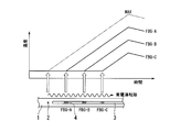
- ⁇ Propagation speed of normal conduction transition ⁇ As shown in FIG. 1, when the temperature change of each FBG is continuously measured from before to after the normal conducting transition occurs in the superconducting wire 1, the time when the temperature rise of each FBG starts can be obtained. Specifically, if the temperature change in the time range before the normal conduction transition occurs is considered as the baseline, the start of the temperature rise is a line representing the temperature change (temperature rise) after the normal conduction transition occurs (or its (Tangent line) is obtained from the position on the time axis where it intersects the baseline.
- the propagation speed of the normal conduction transition can be calculated from the time difference at which the temperature rise of the plurality of FBGs starts and the interval between the plurality of FBGs.
- the interval between the plurality of FBGs is known because a preset value can be used when the FBG is formed in the core of the optical fiber.
- the quotient obtained by dividing the FBG interval by the time difference of the temperature rise start corresponds to the propagation speed of the normal conduction transition.
- the propagation speed of the normal conduction transition can be similarly determined by a statistical method such as taking an average.
- the temperature of the superconducting wire before the occurrence of the normal conducting transition is approximately the same at various places.
- the rate of temperature increase at the location where the normal conducting transition has occurred is approximately the same at each location.
- the temperature rise rate is a temperature difference that rises per unit time, and can be obtained, for example, by averaging time derivatives of temperature changes.
- the maximum temperature Tmax FBG in the FBG in which the normal conduction transition has propagated is that the temperature of the superconducting wire 1 before the occurrence of the normal conduction transition is T 0 , the temperature rise speed due to the normal conduction transition is ⁇ , and the temperature rise at the FBG position.
- the time difference from the start until temperature reached a maximum as a Delta] t 1 it can be determined by approximation by Tmax FBG ⁇ T 0 + ⁇ t 1 .
- the maximum temperature measured in any of the plurality of FBGs is Tmax (corresponding to the above Tmax FBG ), the distance from this FBG to the starting point 2 of the normal conduction transition is L, the temperature rise rate in this FBG is ⁇ , and the normal conduction
- the maximum temperature Tmax O at the starting point 2 of the normal conducting transition can be calculated by (L / V) ⁇ + Tmax, where V is the propagation speed of the transition.
- the value of the temperature rise speed ⁇ in the FBG may be slightly different depending on the distance from the starting part 2, in order to obtain the maximum temperature at the starting part 2 of the normal conduction transition with higher accuracy, It is preferable to use the temperature change measured by the FBG closest to the starting point portion 2.
- the temperature increase rate in each of the plurality of FBGs is obtained from the temperature change of each FBG, and whether or not the temperature increase rate is equal to or higher than a predetermined threshold value, the normal conduction transition occurs at the position of the FBG. It can be determined whether or not the propagation has occurred. As described above, when estimating the propagation speed and maximum temperature of the normal conduction transition, it is necessary that the normal conduction transition propagates to the position of the FBG used for estimation. If the temperature rise rate in the FBG used is equal to or higher than a predetermined threshold value, it can be confirmed that the normal conduction transition has propagated to the position of the FBG.
- the range where the normal conduction transition has occurred can be estimated by doubling the distance from the starting point 2 of the normal conduction transition to the farthest FBG. .
- the propagation range of the normal conducting transition is about twice the distance from the starting point 2 to the FBG-B. Can be estimated.
- the heat generation due to the normal conduction transition is mainly Joule heat according to the current value flowing through the metal stabilization layer 1c and the resistance value of the metal stabilization layer 1c, and the amount of heat generation strongly depends on the current value.
- the predetermined threshold value for determining whether or not the normal conducting transition has propagated to the position of the FBG is preferably set to a different value for each current value to be applied to the superconducting wire.
- the detection method of the normal conduction transition of the superconducting wire according to the present embodiment can be used for a protection device for a superconducting wire during operation.
- the superconducting protection device receives an electrical signal output from the light receiving element 14 in the temperature measuring instrument 10 of FIG. 3, and automatically analyzes it according to the above-described temperature measuring method or normal conducting transition detection method.
- a control device that controls the amount of current applied to the superconducting wire by limiting (decreasing) or shutting down (stopping) the current when an abnormality is detected, an alarm device that issues an alarm to the operator when an abnormality is detected, and operation
- a status display device, a temperature history recording device, and the like can be provided. Thereby, even if a normal conduction transition should occur, the superconducting wire 1 can be prevented from being blown out or burned out, and the superconducting wire 1 can be protected in a good state.
- This embodiment can also be applied to a superconducting coil that can generate an electromagnetic force (hoop stress) by making a superconducting wire into a coil shape and passing a current through the superconducting wire.
- the superconducting coil may be, for example, a pancake-type coil body obtained by bending a superconducting wire in its thickness direction and winding it many times concentrically. Further, two or three or more coil bodies may be laminated. In this case, when converting the Bragg wavelength shift into the temperature of the superconducting wire using the relational expression for measuring the temperature of the superconducting wire from the Bragg wavelength shift (change in Bragg wavelength), input (substitution) into this relational expression.
- the Bragg wavelength shift resulting from subtracting the Bragg wavelength shift of the FBG due to the electromagnetic force is used as the Bragg wavelength shift. It is preferable to apply to the relational expression. Thereby, the temperature change which arises in a superconducting wire can be calculated
- the Bragg wavelength shift of the FBG due to electromagnetic force depends on the current value flowing through the superconducting wire.
- the current value flowing through the superconducting wire and the Bragg wavelength shift due to the electromagnetic force with respect to the current value are measured under conditions where there is no temperature change in advance, and the relationship between the current value and the Bragg wavelength shift due to the electromagnetic force is obtained. It is preferable to keep it.
- the Bragg wavelength shift value due to electromagnetic force can be accurately estimated from this relationship and the value of the current actually energized.
- Example 1 of temperature measurement method In the temperature measuring instrument 10 of the superconducting wire 1 shown in FIG. 3, the optical fiber 3 is bonded and fixed to the superconducting wire 1 as shown in FIG.
- Hastelloy C276 having a width of 5 mm and a thickness of 0.1 mm was used for the base material 1 a of the superconducting wire 1.
- GdBCO GaBa 2 Cu 3 O 7-x
- 0.001 mm that is, 1 ⁇ m
- This superconducting layer has a critical temperature of about 90K and a critical current of about 230A (temperature 77K, value in a magnetic field 0T environment).
- a critical temperature of about 90K and a critical current of about 230A (temperature 77K, value in a magnetic field 0T environment).
- copper having a width of 5 mm and a thickness of 0.1 mm was used.
- the optical fiber 3 in which the fiber Bragg grating 4 (FBG) is formed has an outer diameter of a core made of quartz glass doped with Ge of about 8 ⁇ m and an outer diameter of a clad made of pure silica glass of about 125 ⁇ m. It is covered with a coating layer made of polyimide and having an outer diameter of 150 ⁇ m. As shown in FIG. 4, the optical fiber 3 on which the FBG was formed was fixed on the metal stabilization layer 1c using a polyimide resin (HD Microsystems PI2525: model number) to be the adhesive layer 5.
- a polyimide resin HD Microsystems PI2525: model number
- a polyimide resin to be the adhesive layer 5 is applied so as to cover the periphery of the optical fiber 3, The polyimide resin was cured by heating at 200 ° C. for 1 minute and fixed.
- FBGs 1 to 4 are formed at intervals of 10 mm in the longitudinal direction. These FBGs were produced by a known exposure method using a KrF excimer laser and a uniform phase mask. In this example, the grating length of FBGs 1 to 4 was 6 mm.
- the Bragg wavelengths at room temperature (295 K) and unstrained were prepared at a wavelength interval of about 10 nm with target values of about 1540 nm for FBG1, about 1550 nm for FBG2, about 1560 nm for FBG3, and about 1570 nm for FBG4. The measured value of the Bragg wavelength will be described later together with the measuring method.
- the measuring instrument includes a broadband light source 11 that outputs measurement light, a circulator 12, wavelength reference FBGs 1 and 2 (not shown), a wavelength reference FBGs 1 and 2, and a spectral element 13 that splits Bragg reflected light from FBGs 1 to 4.
- a photodiode (PD) 14 is generally configured. More specifically, an amplified spontaneous emission (ASE) light source is used for the broadband light source 11 and a wavelength variable filter (AOTF) using an acoustooptic effect is used for the spectroscopic element 13.
- ASE amplified spontaneous emission
- AOTF wavelength variable filter
- the ASE light source 11 As the ASE light source 11, a light source that outputs light in the wavelength range of 1520 to 1610 nm was used, and the total light output was 50 mW (that is, 17 dBm).
- the measurement light output from the ASE light source 11 passes through the circulator 12 and enters the wavelength reference FBGs 1 and 2 and the FBGs 1 to 4 of the optical fiber 3 bonded and fixed to the superconducting wire 1. Only the light corresponding to the Bragg wavelength of each FBG is reflected from the measurement light incident on the FBG, and is input to the spectroscopic element 13 via the circulator 12.
- the AOTF used as the spectroscopic element 13 is composed of a planar optical waveguide made of LiNbO 3.
- the AOTF By applying a sine wave having a frequency of 160 to 180 MHz to a comb-shaped electrode provided on the upper surface of the waveguide, the AOTF has a frequency of about 1510 to 1680 nm.
- Light in the wavelength range can be selectively transmitted. Since there is a unique relationship between the frequency of the applied sine wave and the wavelength of transmitted light, the frequency is swept digitally (stepwise) in the above range with respect to time, and input to the PD 14 with respect to time.
- the wavelength of the emitted light can be changed in the range of 1510 to 1680 nm.
- the step frequency of the frequency sweep (frequency interval when performing the frequency sweep in a staircase pattern) is 1.5 kHz, the step time (holding time per step) is 4 ⁇ s, and a high frequency (180 MHz in the range of 160 to 180 MHz). ) To the low frequency (160 MHz) direction. Under this condition, the time required for one frequency sweep is about 53.3 ms from Equation (1).
- the Bragg wavelength of the FBG can be measured at a repetition frequency of 1 / 0.0533 s, that is, 18.75 Hz.
- the wavelength reference FBGs 1 and 2 were used to obtain the relationship between the frequency of the sine wave applied to the AOTF and the transmitted light wavelength.
- the Bragg wavelengths of these wavelength reference FBGs are previously measured to be 1532.100 nm and 1584.500 nm, respectively, at room temperature (295 K) and no strain.
- FIG. 5 is a graph showing the AOTF applied frequency on the horizontal axis and the transmitted light wavelength on the vertical axis. In this way, by complementing the relationship between the applied frequency and the transmitted light wavelength with a linear function, it is possible to precisely associate the applied frequency with the transmitted light wavelength on a one-to-one basis.
- AOTF the relationship between the applied frequency and the transmitted light wavelength changes due to changes and fluctuations in the temperature environment and the like. In actual measurement, this relationship is calculated for each sweep, and the Bragg of FBGs 1 to 4 is based on this. The wavelength was determined.
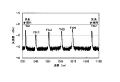
- FIG. 6 shows the reflection spectra of the reference FBGs 1 and 2 and FBGs 1 to 4 measured at room temperature (295 K) and no strain using the measuring instrument described above.
- the Bragg wavelengths of FBGs 1 to 4 obtained from this reflection spectrum were 1540.367 nm for FBG1, 1550.634 nm for FBG2, 1560.660 nm for FBG3, and 1569.300 nm for FBG4.
- FIG. 7A shows a schematic configuration of the test apparatus 20 used in this embodiment. 7B, in the superconducting wire 1 in which the optical fiber 3 in which a plurality of fiber Bragg gratings 4 are formed is bonded and fixed, a heater 6 for generating a normal conducting transition of the superconducting wire 1 is provided in the vicinity of the optical fiber 3.
- a heater 6 for generating a normal conducting transition of the superconducting wire 1 is provided in the vicinity of the optical fiber 3.
- An example of the configuration is shown.
- the superconducting wire 1 was fixed in a coil shape to a cylindrical jig 24 and cooled in a cryogenic vessel 25.
- the inside of the cryogenic container 25 is hermetically sealed by a container body 25a and a lid 25b, and is thermally insulated by vacuum evacuation by a vacuum pump (not shown), and the cooling performance of a refrigerator (not shown) that cools the inside of the cryogenic container 25. Is increasing.
- the superconducting wire 1 was cooled to a predetermined temperature in the cryocontainer 25 using a refrigerator and a semiconductor temperature sensor (Cellnox thermometer: trade name, not shown) provided thereon.
- the optical fiber 3 adhered and fixed to the superconducting wire 1 was taken out of the cryogenic vessel 25 through a vacuum feedthrough that can connect the optical fibers, and the terminal was connected to the temperature measuring instrument 10.
- the heater 6 installed on the superconducting wire 1 is a heater for heating the superconducting wire 1. When the heater 6 is energized, the temperature of the superconducting wire 1 can be raised to a temperature equal to or higher than the critical temperature of the superconducting layer 1b, and a normal conducting transition can be intentionally generated.
- the electrodes 23 provided at both ends of the superconducting wire 1 are connected via a vacuum feedthrough capable of connecting the power cables 22 to each other, and the superconducting wire 1 can be energized from the current terminal of the power source 21.
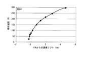
- FIG. 8 shows the relationship between the absolute temperature of the FBG 1 and the Bragg wavelength shift, and the sensitivity (the Bragg wavelength shift amount per unit temperature change) obtained from this Bragg wavelength shift characteristic.
- the sensitivity (indicated by a line without the symbol ( ⁇ ) in FIG.
- Equation (2) is the result obtained by approximating the relationship between the absolute temperature (x) and the Bragg wavelength shift (y) shown in Equation (2) with a quartic equation as x. Obtained by differentiating. This result can be expressed by equation (3).
- the units in the formulas (2) and (3) are absolute temperature (x) K, wavelength shift (y) pm, and sensitivity (y ′) pm / K.
- Example 2 of temperature measurement method In the above described (Embodiment 1 of the temperature measurement method), the temperature is calculated using the approximate expression obtained for each FBG. However, the temperature may be calculated using one approximate expression given in advance. . Table 2 shows the results of calculating the temperature using the above equations (4) to (7) with respect to the wavelength shift of the FBG 1. Since the equation (4) is a relational expression between the absolute temperature and the Bragg wavelength shift obtained in the experiment using the FBG1, the same result as in Table 1 is obtained, but it is obtained in the experiment using the FBGs 2 to 4. Even using the equations (5) to (7), a measurement accuracy of ⁇ 20 K was obtained in the temperature range of 25 to 295 K.
- FIG. 13 is a diagram in which the results of FIGS. 9 to 12 are plotted in one graph.
- FBGs 1 to 4 indicate that the relationship between the Bragg wavelength shift and the temperature change is very close. Further, in the normal conduction transition detection at 77K to be performed thereafter, it is considered that the temperature measurement accuracy is about ⁇ 20K. Although the temperature accuracy is inferior to the case of calculating from the approximate expression obtained by each FBG in the above (Example 1 of temperature measurement method), by using one approximate expression given in advance, for each FBG This method is useful in that it is not necessary to previously calculate the relationship between absolute temperature and Bragg wavelength shift.
- Example 1 of detection method of normal conduction transition Next, using the test apparatus shown in FIG. 7A and FIG. 7B, the normal conducting transition is intentionally generated for the superconducting wire 1 of the present embodiment, the normal conducting transition is detected by FBG, and the temperature generated at this time is detected. Measurement was performed.
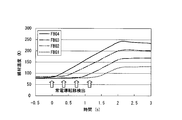
- the superconducting wire 1 is cooled and held at 77 K, which is lower than the critical temperature of the superconducting layer, and the superconducting layer 1 is locally heated by energizing the heater 6 for 3 seconds with a current of 160 A being passed through the superconducting layer. This is the result of measuring the wire temperature at each of the FBGs 1 to 4.
- the FBG 4 adjacent to the heater 6 detected the heat generation earliest, and the FBG 1 far from the heater 6 detected the heat generation the latest.
- the time when the FBG 4 adjacent to the heater 6 detects heat generation is defined as 0 seconds, and when the heat generation of the FBG 1 far from the heater 6 is detected and time sufficiently passes, it is 2.1 seconds.
- the electric current supplied to the superconducting wire 1 is interrupted. This result indicates that the normal conduction transition generated in the heater 6 propagates in the longitudinal direction of the superconducting wire 1.
- the detection time difference of each FBG shows the propagation speed of a normal conduction transition, and the inclination of a wire temperature change shows a temperature rise rate.
- the propagation speed obtained from this result was about 25 mm / s, and the temperature rise speed was about 80 K / s. From these speeds, the maximum temperature generated at the starting point of the normal conduction transition, that is, at the center of the heater 6, can be obtained using the equation (8).
- 10 mm is the distance between the FBG 4 and the heater 6, and 245K is the maximum temperature measured by the FBG 4 shown in FIG. Since the result of Equation (8) is 277K and the temperature measurement accuracy at 77 to 295K obtained in advance is ⁇ 5K, it can be estimated that the maximum temperature generated in the wire is about 277 ⁇ 5K.
- the propagation speed of the normal conduction transition and the temperature rise speed of the superconducting wire can be measured. Further, the maximum temperature at the starting point of the normal conduction transition, that is, the maximum temperature generated in the superconducting wire can be measured from these speeds. From the comparison between the maximum temperature and a preset safety reference temperature, it is possible to determine the necessity for inspection and repair of the superconducting wire.
- FIG. 15 is a result of measuring the wire temperature by FBG when the superconducting wire 1 is locally heated by energizing the heater for 1.5 seconds.
- the time when the FBG 4 detects heat generation is defined as 0 seconds, and the current flowing through the superconducting wire 1 is cut off at 1.1 seconds.
- the rate of temperature increase was about 80 K / s for FBG4, about 65 K / s for FBG3, about 40 K / s for FBG2, and about 15 K / s for FBG1.
- the range showing the normal conduction transition in this embodiment is from the center of the heater to the FBG 3 and the distance is about 20 mm.
- the range in which the normal conduction transition is actually performed is about 40 mm.
- the normal conducting transition range can be detected. Therefore, even if it is determined that inspection or repair of the superconducting wire is necessary, the range can be limited, and the work efficiency can be improved.
- any one of the FBGs FBG4 detects heat generation, and then interrupts the current that is applied to the superconducting wire 1 at an early stage. It can be seen that the range of the normal conducting transition can be reduced.
- a control device that controls the amount of current supplied to the superconducting wire by limiting (decreasing) or interrupting (stopping) the current, and an alarm device that issues an alarm to the worker when an abnormality is detected
- a control device that controls the amount of current supplied to the superconducting wire by limiting (decreasing) or interrupting (stopping) the current
- an alarm device that issues an alarm to the worker when an abnormality is detected
- FIG. 16 is a graph showing changes over time in the wire temperature measured by the FBG 4 when the current supplied to the superconducting wire is changed to 160A, 190A, and 220A and the heater is supplied for 1.5 seconds.
- the plot of 160A cites the result of Example 2 (FIG. 15).
- the time when the FBG 4 detects heat generation is defined as 0 seconds, and the current flowing to the superconducting wire 1 is cut off when the FBG reaches 150K or more.
- the rate of temperature increase was about 80 K / s at 160 A, about 140 K / s at 190 A, and about 160 K / s at 220 A.
- FIG. 17 is a graph showing the relationship between the square value of the current passed through the superconducting wire 1 and the temperature rise rate.
- the rate of temperature increase increased almost in direct proportion to the square value of the current passed through the superconducting wire 1.
- current value current value is I
- R resistance value
- the generated Joule heat is directly proportional to R ⁇ I 2 . That is, the reason why the rate of temperature rise is directly proportional to the square value of the current passed through the superconducting wire is that the heat generated in the normal conducting transition portion is caused by Joule heat generated in the metal stabilizing layer.
- the temperature increase due to the normal conduction transition increases as the value of the current applied to the superconducting wire increases. It is necessary to consider that the speed increases.
- the maximum temperature measured on the FBG 4 is about 160 to 170 K, but the maximum temperature at the starting point 2 is the same as in the above (Example 1 of the normal conduction transition detection method). As a result of the estimation, a result is obtained that the higher the current value, the higher the maximum temperature at the starting point.
- the superconducting wire 1 is fixed in a coil shape, but the present invention is not limited to these embodiments.
- the superconducting wire that converts a superconducting wire into a cable and transmits a large current is used. It can also be used for cables.
- Example 4 of detection method of normal conduction transition
- the superconducting wire 1 was cooled and held at 50K, and a 3T magnetic field was applied to an electromagnet (not shown) provided on the outer periphery of the superconducting wire 1.
- the critical current of the superconducting wire 1 at 50K and 3T is about 200A.
- an electromagnetic force hoop stress
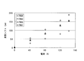
- FIG. 18 is a graph showing changes in the Bragg wavelengths of the FBGs 1 to 4 when the value of the current applied to the superconducting wire 1 is changed to 40A, 80A, 120A, and 140A.
- a tensile strain is generated in the longitudinal direction of the superconducting wire 1, so that the tensile strain is transmitted to the FBGs 1 to 4. Therefore, the lattice spacing ⁇ of the FBG is extended, and the Bragg wavelength ⁇ B is shifted to the long wavelength side. It has been confirmed that the value of the current applied to the superconducting wire 1 and the change in the Bragg wavelength are almost directly proportional to the value of the current applied to the superconducting wire 1, although there is a slight difference between FBGs 1 to 4.
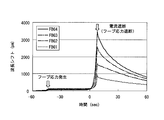
- FIG. 19 shows the result of measuring the change in the Bragg wavelength of each of the FBGs 1 to 4 at this time.
- FIG. 20 is an enlarged graph of the section of ⁇ 2 to 12 seconds in FIG.
- the time when the Bragg wavelength of the FBG 4 has greatly changed is defined as 0 seconds, and the current supplied to the superconducting wire 1 is cut off at the time of 8 seconds.
- FIG. 21 shows the result of the Bragg wavelength shift obtained by subtracting the Bragg wavelength shift caused by the hoop stress.
- the temperature of the superconducting wire 1 is obtained based on the Bragg wavelength shift obtained in FIG. From the relationship between the absolute temperature and the Bragg wavelength shift obtained in advance in Example 1, the relationship between the wavelength shift from 50K and the absolute temperature is obtained, and a result obtained by approximating this to a quartic function and the correlation function (R 2 ) of this approximate expression Is shown in equations (9) to (12).
- the units in the equations (9) to (12) are K for the absolute temperature (y) and nm for the wavelength shift (x).
- FIG. 21 The Bragg wavelength shift obtained in FIG. 21 was converted into the temperature of the superconducting wire 1 using the mathematical formulas (9) to (12) obtained above.
- FIG. 22 is a graph showing the results converted to the temperature of the superconducting wire 1.
- the temperature change generated in the superconducting wire 1 could be accurately obtained without converting the Bragg wavelength shift due to the hoop stress as a temperature.
- the propagation speed obtained from this result was about 11 mm / s, and the temperature rise rate was about 25 K / s.
- the maximum temperature was estimated at 284K.
- an electromagnetic force (hoop stress) was generated by the electromagnet provided on the outer periphery of the superconducting wire 1, but a large coil was produced using a long superconducting wire and a current was passed through the hoop.
- the present invention can also be used when stress is generated.
Landscapes
- Physics & Mathematics (AREA)
- General Physics & Mathematics (AREA)
- Biochemistry (AREA)
- Life Sciences & Earth Sciences (AREA)
- Chemical & Material Sciences (AREA)
- Analytical Chemistry (AREA)
- Health & Medical Sciences (AREA)
- General Health & Medical Sciences (AREA)
- Immunology (AREA)
- Pathology (AREA)
- Superconductors And Manufacturing Methods Therefor (AREA)
- Measuring Temperature Or Quantity Of Heat (AREA)
- Investigating Or Analyzing Materials Using Thermal Means (AREA)
Abstract
Cette invention concerne un procédé de détection du passage à un courant normal d'une bobine supraconductrice, ladite bobine comprenant un matériau de base, une couche supraconductrice d'une température critique de 77 °K ou plus et une couche de stabilisation métallique. Une fibre optique, les nombreuses fibres optiques à réseau de Bragg étant formées dans le sens longitudinal d'un cœur, est liée et fixée à la bobine supraconductrice ; les variations de la longueur d'onde de Bragg des fibres optiques à réseau de Bragg en rapport avec les variations thermiques de la bobine supraconductrice sont calculées au préalable, et une formule permettant de calculer la température de la bobine supraconductrice d'après les variations de la longueur d'onde de Bragg est définie ; les nombreuses variations thermiques des fibres optiques à réseau de Bragg avant et après le passage au courant normal par la bobine supraconductrice sont déterminées à l'aide de la formule ; et la vitesse de propagation du passage au courant normal est calculée d'après la différence de temps entre le début de l'augmentation de la température des nombreuses fibres optiques à réseau de Bragg et l'intervalle entre lesdites fibres optiques à réseau de Bragg.
Priority Applications (4)
| Application Number | Priority Date | Filing Date | Title |
|---|---|---|---|
| JP2012522487A JP5393888B2 (ja) | 2010-06-28 | 2011-04-06 | 超電導線材の常電導転移の検出方法 |
| CN201180005090.8A CN102667456B (zh) | 2010-06-28 | 2011-04-06 | 超导线材的常导转变的检测方法 |
| EP11800486.0A EP2587254B1 (fr) | 2010-06-28 | 2011-04-06 | Procédé de détection du passage à l'état normal d'une bobine supraconductrice |
| US13/728,570 US9488606B2 (en) | 2010-06-28 | 2012-12-27 | Method for detecting non-superconducting transition of superconducting wire |
Applications Claiming Priority (4)
| Application Number | Priority Date | Filing Date | Title |
|---|---|---|---|
| JP2010146304 | 2010-06-28 | ||
| JP2010-146304 | 2010-06-28 | ||
| JP2011057939 | 2011-03-16 | ||
| JP2011-057939 | 2011-03-16 |
Related Child Applications (1)
| Application Number | Title | Priority Date | Filing Date |
|---|---|---|---|
| US13/728,570 Continuation US9488606B2 (en) | 2010-06-28 | 2012-12-27 | Method for detecting non-superconducting transition of superconducting wire |
Publications (1)
| Publication Number | Publication Date |
|---|---|
| WO2012002016A1 true WO2012002016A1 (fr) | 2012-01-05 |
Family
ID=45401753
Family Applications (1)
| Application Number | Title | Priority Date | Filing Date |
|---|---|---|---|
| PCT/JP2011/058700 Ceased WO2012002016A1 (fr) | 2010-06-28 | 2011-04-06 | Procédé de détection du passage au courant normal d'une bobine supraconductrice |
Country Status (5)
| Country | Link |
|---|---|
| US (1) | US9488606B2 (fr) |
| EP (1) | EP2587254B1 (fr) |
| JP (1) | JP5393888B2 (fr) |
| CN (1) | CN102667456B (fr) |
| WO (1) | WO2012002016A1 (fr) |
Cited By (3)
| Publication number | Priority date | Publication date | Assignee | Title |
|---|---|---|---|---|
| RU2637398C2 (ru) * | 2012-11-15 | 2017-12-04 | Конинклейке Филипс Н.В. | Мрт с участием распределенного датчика для контроля температуры и/или деформации кабелей катушки и фильтров |
| RU2642125C2 (ru) * | 2012-12-18 | 2018-01-24 | Конинклейке Филипс Н.В. | Многократно используемый температурный датчик, безопасный при проведении магнитно-резонансной томографии, для измерения температуры поверхности и тела |
| CN109682853A (zh) * | 2019-01-09 | 2019-04-26 | 南京大学 | 一种基于fbg的冻土含冰量分布式原位测量方法及装置 |
Families Citing this family (18)
| Publication number | Priority date | Publication date | Assignee | Title |
|---|---|---|---|---|
| CN104157366B (zh) * | 2014-07-31 | 2017-08-08 | 上海超导科技股份有限公司 | 内封测量光纤的超导带材及其制备方法、装置 |
| CN104390721A (zh) * | 2014-11-24 | 2015-03-04 | 南京信息工程大学 | 温度传感器、温度测量方法及装置 |
| CN104614641A (zh) * | 2015-01-09 | 2015-05-13 | 山东航天电子技术研究所 | 一种准分布式光纤光栅导线故障定位系统与方法 |
| US20200123052A1 (en) * | 2016-01-08 | 2020-04-23 | North Carolina State University | Enhanced optical fibers for low temperature sensing |
| JP6328683B2 (ja) * | 2016-04-12 | 2018-05-23 | ファナック株式会社 | 小型チラーが使用可能なレーザ装置 |
| CN105997016B (zh) * | 2016-06-14 | 2018-11-02 | 广州视源电子科技股份有限公司 | 基于电子体温计识别测量对象的方法及其系统 |
| WO2019027964A1 (fr) * | 2017-07-31 | 2019-02-07 | North Carolina State University | Câbles supraconducteurs à auto-surveillance ayant des fibres optiques intégrées |
| DE102017119810B4 (de) * | 2017-08-29 | 2019-05-09 | fos4X GmbH | Optoelektrischer Chip |
| US11879789B2 (en) * | 2019-07-02 | 2024-01-23 | International Business Machines Corporation | On-chip thermometer for superconducting quantum computing devices |
| US11674854B2 (en) | 2019-07-02 | 2023-06-13 | International Business Machines Corporation | Mapping temperature distribution in superconducting devices |
| US12070753B2 (en) * | 2020-03-30 | 2024-08-27 | Fei Company | Method for temperature monitoring in cryo-electron microscopy |
| GB202007785D0 (en) * | 2020-05-26 | 2020-07-08 | Royal Holloway & Bedford New College | Current sensing noise thermometer |
| CN111665462B (zh) * | 2020-06-08 | 2024-06-04 | 华中科技大学 | 一种高温超导磁体失超检测装置及方法 |
| CN112098776B (zh) * | 2020-09-18 | 2022-11-08 | 国网江苏省电力有限公司无锡供电分公司 | 一种覆冰及污闪电流监测系统及方法 |
| EP4381259A1 (fr) * | 2021-08-06 | 2024-06-12 | Massachusetts Institute Of Technology | Détection de transition résistive de fibre optique |
| CN115773770A (zh) * | 2022-11-03 | 2023-03-10 | 先进能源科学与技术广东省实验室 | 一种分布式光纤传感器、应用及制作方法 |
| WO2024186379A2 (fr) * | 2022-12-28 | 2024-09-12 | The Penn State Research Foundation | Gestion dynamique d'aimants supraconducteurs |
| WO2024173669A1 (fr) * | 2023-02-16 | 2024-08-22 | Commonwealth Fusion Systems Llc | Motif de réseau de bragg à rampe linéaire dense pour détection de trempe dans des aimants supraconducteurs à haute température |
Citations (4)
| Publication number | Priority date | Publication date | Assignee | Title |
|---|---|---|---|---|
| JPH07170721A (ja) | 1992-06-26 | 1995-07-04 | Canon Inc | 超伝導モーター、超伝導マグネット装置、超伝導アクチュエーター、超伝導線のクエンチ検出方法及び超伝導線 |
| JPH08304271A (ja) | 1995-05-11 | 1996-11-22 | Canon Inc | 超伝導体クエンチ検出装置及び検出方法 |
| JP2577682B2 (ja) | 1992-04-20 | 1997-02-05 | 株式会社日立製作所 | 超電導体の温度測定方法及び装置並びに超電導マグネットのクエンチ予知方法及び装置 |
| US6072922A (en) | 1998-06-19 | 2000-06-06 | Science And Engineering Applications Company, Inc. | Cryogenic fiber optic temperature sensor |
Family Cites Families (7)
| Publication number | Priority date | Publication date | Assignee | Title |
|---|---|---|---|---|
| US5065087A (en) * | 1988-10-04 | 1991-11-12 | Sharp Kabushiki Kaisha | Apparatus for observing a superconductive phenomenon in a superconductor |
| JPH11162269A (ja) * | 1997-11-27 | 1999-06-18 | Toshiba Corp | 超電導機器 |
| JP3519333B2 (ja) * | 2000-02-10 | 2004-04-12 | エヌ・ティ・ティ・アドバンステクノロジ株式会社 | 光ファイバセンサ |
| DE102006025700B4 (de) * | 2006-06-01 | 2009-04-16 | Siemens Ag | Optische Messeinrichtung zur Temperaturbestimmung in einer kryogenen Umgebung und temperaturüberwachbare Wickelanordnung |
| CN1963477B (zh) * | 2006-11-08 | 2011-03-30 | 中国科学院电工研究所 | 一种非接触连续测量超导线/带材n指数均匀性的方法和装置 |
| CN101126787B (zh) * | 2007-09-28 | 2010-06-09 | 中国科学院电工研究所 | 一种超导线圈失超检测方法 |
| CN102305804B (zh) * | 2011-05-19 | 2013-06-05 | 北京鼎臣超导科技有限公司 | 一种高温超导材料超导转变温度测量装置及测量方法 |
-
2011
- 2011-04-06 WO PCT/JP2011/058700 patent/WO2012002016A1/fr not_active Ceased
- 2011-04-06 EP EP11800486.0A patent/EP2587254B1/fr not_active Not-in-force
- 2011-04-06 CN CN201180005090.8A patent/CN102667456B/zh not_active Expired - Fee Related
- 2011-04-06 JP JP2012522487A patent/JP5393888B2/ja not_active Expired - Fee Related
-
2012
- 2012-12-27 US US13/728,570 patent/US9488606B2/en active Active
Patent Citations (4)
| Publication number | Priority date | Publication date | Assignee | Title |
|---|---|---|---|---|
| JP2577682B2 (ja) | 1992-04-20 | 1997-02-05 | 株式会社日立製作所 | 超電導体の温度測定方法及び装置並びに超電導マグネットのクエンチ予知方法及び装置 |
| JPH07170721A (ja) | 1992-06-26 | 1995-07-04 | Canon Inc | 超伝導モーター、超伝導マグネット装置、超伝導アクチュエーター、超伝導線のクエンチ検出方法及び超伝導線 |
| JPH08304271A (ja) | 1995-05-11 | 1996-11-22 | Canon Inc | 超伝導体クエンチ検出装置及び検出方法 |
| US6072922A (en) | 1998-06-19 | 2000-06-06 | Science And Engineering Applications Company, Inc. | Cryogenic fiber optic temperature sensor |
Non-Patent Citations (3)
| Title |
|---|
| See also references of EP2587254A4 |
| WOLFGANG ECKE ET AL.: "Fiber optical grating sensors for structural health monitoring at cryogenic temperatures", PROCEEDINGS OF SPIE, vol. 6530, 2007, pages 653002, XP002741377 |
| WOLFGANG ECKE ET AL.: "Fiber-optic Bragg grating sensors for structural health monitoring at cryogenic temperatures", PROCEEDINGS OF SPIE, vol. 6530, 2007, pages 1 - 10, XP055074586 * |
Cited By (4)
| Publication number | Priority date | Publication date | Assignee | Title |
|---|---|---|---|---|
| RU2637398C2 (ru) * | 2012-11-15 | 2017-12-04 | Конинклейке Филипс Н.В. | Мрт с участием распределенного датчика для контроля температуры и/или деформации кабелей катушки и фильтров |
| RU2642125C2 (ru) * | 2012-12-18 | 2018-01-24 | Конинклейке Филипс Н.В. | Многократно используемый температурный датчик, безопасный при проведении магнитно-резонансной томографии, для измерения температуры поверхности и тела |
| CN109682853A (zh) * | 2019-01-09 | 2019-04-26 | 南京大学 | 一种基于fbg的冻土含冰量分布式原位测量方法及装置 |
| CN109682853B (zh) * | 2019-01-09 | 2024-02-13 | 南京大学 | 一种基于fbg的冻土含冰量分布式原位测量方法及装置 |
Also Published As
| Publication number | Publication date |
|---|---|
| US9488606B2 (en) | 2016-11-08 |
| JP5393888B2 (ja) | 2014-01-22 |
| JPWO2012002016A1 (ja) | 2013-08-22 |
| CN102667456B (zh) | 2014-06-25 |
| EP2587254A1 (fr) | 2013-05-01 |
| EP2587254B1 (fr) | 2017-11-29 |
| CN102667456A (zh) | 2012-09-12 |
| US20160047763A1 (en) | 2016-02-18 |
| EP2587254A4 (fr) | 2015-08-05 |
Similar Documents
| Publication | Publication Date | Title |
|---|---|---|
| JP5393888B2 (ja) | 超電導線材の常電導転移の検出方法 | |
| US20140268130A1 (en) | Method for detecting non-superconducting transition of superconducting wire | |
| US6876785B1 (en) | Embedded sensor, method for producing, and temperature/strain fiber optic sensing system | |
| Rai | Temperature sensors and optical sensors | |
| Wanser | Fundamental phase noise limit in optical fibres due to temperature fluctuations | |
| Chiuchiolo et al. | Cryogenic-temperature profiling of high-power superconducting lines using local and distributed optical-fiber sensors | |
| Li et al. | Shape deposition manufacturing of smart metallic structures with embedded sensors | |
| JP5645713B2 (ja) | 超電導コイル装置、及び超電導コイルの常電導転移の検出方法 | |
| KR970007812B1 (ko) | 복굴절 온도센서 | |
| Dedyulin et al. | Packaging and precision testing of fiber-Bragg-grating and silicon ring-resonator thermometers: current status and challenges | |
| JP2006047154A (ja) | 光ファイバ温度センサ及びその製造方法 | |
| DeMiguel-Soto et al. | Interferometric vs wavelength selective optical fiber sensors for cryogenic temperature measurements | |
| Soman et al. | Design of cryogenic temperature sensors using copper-coated fiber Bragg gratings | |
| EP4022689B1 (fr) | Système de surveillance hotspot pour dispositif superconducteur | |
| Kajanto et al. | A silicon-based fibre-optic temperature sensor | |
| WO2017091073A1 (fr) | Dispositif capteur à fibre optique cryogénique | |
| RU2813237C1 (ru) | Волоконно-оптический датчик температуры на основе термооптического эффекта кремния | |
| CN223992647U (zh) | 一种fbg与直接带隙半导体混合式光纤温度传感器 | |
| KR102462081B1 (ko) | 광섬유 프로브 방식의 온도센서를 이용한 전기설비의 온도 열화 모니터링 시스템 | |
| JP5977698B2 (ja) | 光ファイバ温度センサ | |
| Beheim et al. | Laser-annealed thin-film fiber-optic temperature sensor | |
| Lord et al. | Remote measurement of temperature in the presence of a strong magnetic field | |
| Freitas | Optical fiber temperature sensors for cryogenic applications | |
| de Lima Junior et al. | A fiber optical thermometer for high power transformer monitoring utilizing the thermo-optical phase transition of VO2 | |
| Grattan et al. | Optical-fiber sensors: Temperature and pressure sensors |
Legal Events
| Date | Code | Title | Description |
|---|---|---|---|
| 121 | Ep: the epo has been informed by wipo that ep was designated in this application |
Ref document number: 11800486 Country of ref document: EP Kind code of ref document: A1 |
|
| WWE | Wipo information: entry into national phase |
Ref document number: 2012522487 Country of ref document: JP |
|
| NENP | Non-entry into the national phase |
Ref country code: DE |
|
| REEP | Request for entry into the european phase |
Ref document number: 2011800486 Country of ref document: EP |
|
| WWE | Wipo information: entry into national phase |
Ref document number: 2011800486 Country of ref document: EP |