WO2012002115A1 - Dispositif d'endoscope - Google Patents
Dispositif d'endoscope Download PDFInfo
- Publication number
- WO2012002115A1 WO2012002115A1 PCT/JP2011/063064 JP2011063064W WO2012002115A1 WO 2012002115 A1 WO2012002115 A1 WO 2012002115A1 JP 2011063064 W JP2011063064 W JP 2011063064W WO 2012002115 A1 WO2012002115 A1 WO 2012002115A1
- Authority
- WO
- WIPO (PCT)
- Prior art keywords
- signal
- color
- circuit
- enhancement
- matrix
- Prior art date
- Legal status (The legal status is an assumption and is not a legal conclusion. Google has not performed a legal analysis and makes no representation as to the accuracy of the status listed.)
- Ceased
Links
Images







Classifications
-
- A—HUMAN NECESSITIES
- A61—MEDICAL OR VETERINARY SCIENCE; HYGIENE
- A61B—DIAGNOSIS; SURGERY; IDENTIFICATION
- A61B1/00—Instruments for performing medical examinations of the interior of cavities or tubes of the body by visual or photographical inspection, e.g. endoscopes; Illuminating arrangements therefor
- A61B1/00002—Operational features of endoscopes
- A61B1/00004—Operational features of endoscopes characterised by electronic signal processing
- A61B1/00009—Operational features of endoscopes characterised by electronic signal processing of image signals during a use of endoscope
-
- A—HUMAN NECESSITIES
- A61—MEDICAL OR VETERINARY SCIENCE; HYGIENE
- A61B—DIAGNOSIS; SURGERY; IDENTIFICATION
- A61B1/00—Instruments for performing medical examinations of the interior of cavities or tubes of the body by visual or photographical inspection, e.g. endoscopes; Illuminating arrangements therefor
- A61B1/00163—Optical arrangements
- A61B1/00186—Optical arrangements with imaging filters
-
- A—HUMAN NECESSITIES
- A61—MEDICAL OR VETERINARY SCIENCE; HYGIENE
- A61B—DIAGNOSIS; SURGERY; IDENTIFICATION
- A61B1/00—Instruments for performing medical examinations of the interior of cavities or tubes of the body by visual or photographical inspection, e.g. endoscopes; Illuminating arrangements therefor
- A61B1/06—Instruments for performing medical examinations of the interior of cavities or tubes of the body by visual or photographical inspection, e.g. endoscopes; Illuminating arrangements therefor with illuminating arrangements
- A61B1/0638—Instruments for performing medical examinations of the interior of cavities or tubes of the body by visual or photographical inspection, e.g. endoscopes; Illuminating arrangements therefor with illuminating arrangements providing two or more wavelengths
-
- A—HUMAN NECESSITIES
- A61—MEDICAL OR VETERINARY SCIENCE; HYGIENE
- A61B—DIAGNOSIS; SURGERY; IDENTIFICATION
- A61B1/00—Instruments for performing medical examinations of the interior of cavities or tubes of the body by visual or photographical inspection, e.g. endoscopes; Illuminating arrangements therefor
- A61B1/06—Instruments for performing medical examinations of the interior of cavities or tubes of the body by visual or photographical inspection, e.g. endoscopes; Illuminating arrangements therefor with illuminating arrangements
- A61B1/0646—Instruments for performing medical examinations of the interior of cavities or tubes of the body by visual or photographical inspection, e.g. endoscopes; Illuminating arrangements therefor with illuminating arrangements with illumination filters
-
- A—HUMAN NECESSITIES
- A61—MEDICAL OR VETERINARY SCIENCE; HYGIENE
- A61B—DIAGNOSIS; SURGERY; IDENTIFICATION
- A61B1/00—Instruments for performing medical examinations of the interior of cavities or tubes of the body by visual or photographical inspection, e.g. endoscopes; Illuminating arrangements therefor
- A61B1/06—Instruments for performing medical examinations of the interior of cavities or tubes of the body by visual or photographical inspection, e.g. endoscopes; Illuminating arrangements therefor with illuminating arrangements
- A61B1/0655—Control therefor
-
- A—HUMAN NECESSITIES
- A61—MEDICAL OR VETERINARY SCIENCE; HYGIENE
- A61B—DIAGNOSIS; SURGERY; IDENTIFICATION
- A61B1/00—Instruments for performing medical examinations of the interior of cavities or tubes of the body by visual or photographical inspection, e.g. endoscopes; Illuminating arrangements therefor
- A61B1/00002—Operational features of endoscopes
- A61B1/00059—Operational features of endoscopes provided with identification means for the endoscope
-
- A—HUMAN NECESSITIES
- A61—MEDICAL OR VETERINARY SCIENCE; HYGIENE
- A61B—DIAGNOSIS; SURGERY; IDENTIFICATION
- A61B1/00—Instruments for performing medical examinations of the interior of cavities or tubes of the body by visual or photographical inspection, e.g. endoscopes; Illuminating arrangements therefor
- A61B1/04—Instruments for performing medical examinations of the interior of cavities or tubes of the body by visual or photographical inspection, e.g. endoscopes; Illuminating arrangements therefor combined with photographic or television appliances
- A61B1/043—Instruments for performing medical examinations of the interior of cavities or tubes of the body by visual or photographical inspection, e.g. endoscopes; Illuminating arrangements therefor combined with photographic or television appliances for fluorescence imaging
-
- A—HUMAN NECESSITIES
- A61—MEDICAL OR VETERINARY SCIENCE; HYGIENE
- A61B—DIAGNOSIS; SURGERY; IDENTIFICATION
- A61B1/00—Instruments for performing medical examinations of the interior of cavities or tubes of the body by visual or photographical inspection, e.g. endoscopes; Illuminating arrangements therefor
- A61B1/04—Instruments for performing medical examinations of the interior of cavities or tubes of the body by visual or photographical inspection, e.g. endoscopes; Illuminating arrangements therefor combined with photographic or television appliances
- A61B1/05—Instruments for performing medical examinations of the interior of cavities or tubes of the body by visual or photographical inspection, e.g. endoscopes; Illuminating arrangements therefor combined with photographic or television appliances characterised by the image sensor, e.g. camera, being in the distal end portion
- A61B1/051—Details of CCD assembly
-
- A—HUMAN NECESSITIES
- A61—MEDICAL OR VETERINARY SCIENCE; HYGIENE
- A61B—DIAGNOSIS; SURGERY; IDENTIFICATION
- A61B1/00—Instruments for performing medical examinations of the interior of cavities or tubes of the body by visual or photographical inspection, e.g. endoscopes; Illuminating arrangements therefor
- A61B1/06—Instruments for performing medical examinations of the interior of cavities or tubes of the body by visual or photographical inspection, e.g. endoscopes; Illuminating arrangements therefor with illuminating arrangements
- A61B1/0661—Endoscope light sources
- A61B1/0669—Endoscope light sources at proximal end of an endoscope
Definitions
- the present invention relates to an endoscope apparatus that performs image processing on imaging means mounted on an endoscope.
- the circuit scale can be reduced because an enhancement circuit that performs one system of signal processing is sufficient.
- the RGB signal as the three primary color signals generated based on the enhanced luminance signal and the unenhanced color difference signal
- the image information reproduced for each color component changes, and blood vessels in the observation image of the endoscope Changes in brightness and color tone occur in an image or the like.
- Japanese Patent Application Laid-Open No. 2006-61621 as a second conventional example of an endoscope apparatus using an electronic endoscope equipped with an image pickup device having a color filter includes a luminance signal, a color difference signal, What performs emphasis processing is disclosed.
- the present invention has been made in view of the above points, and an object thereof is to provide an endoscope apparatus capable of performing enhancement processing while suppressing false color and color moire while improving the reproducibility of a living mucous membrane. To do.
- An endoscope apparatus includes: an imaging unit including a color separation unit that color-separates and receives a return light of light irradiated on a subject by an illumination unit; Enhancement processing means for performing sharpness enhancement processing on the image signal based thereon, and processing of the enhancement processing means according to the spectral characteristics of the return light incident on the imaging means, which differs depending on the type and observation mode of the imaging means.
- Storage means for storing information for changing the contents, and control means for performing control to change the processing contents of the emphasis processing means based on the information in the storage means.
- sequence of the color filter of 2nd Embodiment The figure which shows the structure of the 2 plate imaging part periphery part provided in the front-end
- the image pickup unit has an enhancement characteristic for an emphasized signal that is enhanced by an enhancement circuit according to a complementary color single plate, primary color single plate / 2 plate, and primary color 3 plate.
- the imaging unit has an enhancement characteristic for an emphasized signal that is emphasized by an enhancement circuit according to a complementary color single plate, primary color single plate, two plates, or three plates
- an enhancement circuit according to a complementary color single plate, primary color single plate, two plates, or three plates
- the figure which shows the example of a setting The figure which shows the example of a setting of the emphasis characteristic with respect to the to-be-enhanced signal in which the imaging part is emphasized by the emphasis circuit according to a complementary color single board, primary color single board, 2 board, and 3 board in the case of producing an observation image by imaging blue light .
- an endoscope apparatus 1 includes an electronic endoscope (hereinafter simply referred to as an endoscope) 2 that is inserted into a body cavity and performs an endoscopic examination, A light source device 3 for supplying illumination light to the endoscope 2.
- the endoscope apparatus 1 drives an imaging means built in the endoscope 2 and also performs a video processor 4 as an endoscope video signal processing apparatus that performs signal processing on an output signal of the imaging means, A monitor 5 that displays an image obtained by performing signal processing on the captured image captured by the imaging unit as an endoscopic image when the video signal output from the video processor 4 is input.
- the endoscope 2 includes an elongated insertion portion 7, an operation portion 8 provided at the rear end of the insertion portion 7, and a universal cable 9 extending from the operation portion 8.
- the light guide connector 11 at the end of this is detachably connected to the light source device 3, and the signal connector is detachably connected to the video processor 4.
- a light guide 13 that transmits illumination light is inserted into the insertion portion 7, and the light guide connector 11 at the end on the hand side of the light guide 13 is connected to the light source device 3.
- Illumination light is supplied to the light guide 13.
- the light source device 3 In the normal white light observation (WLI) mode, the light source device 3 generates white illumination light that covers the visible wavelength region as illumination light and supplies it to the light guide 13.
- WLI normal white light observation
- narrow-band illumination light is generated as illumination light and supplied to the light guide 13.
- the switching instruction between the WLI mode and the NBI mode can be performed by, for example, the mode switch 14 configured by a scope switch provided in the operation unit 8 of the endoscope 2.
- the mode change switch 14 may be constituted by a foot switch, or a mode change switch may be provided on the front panel of the video processor 4. You may comprise with the keyboard which is not illustrated.
- the switching signal from the mode switch 14 is input to the control circuit 15 in the video processor 4. When the switching signal is input, the control circuit 15 controls the filter insertion / removal mechanism 16 of the light source device 3 to perform normal operation. Selectively switch between white light and narrowband illumination light.
- control circuit 15 also performs control for switching characteristics of the signal processing system in the video processor 4 in conjunction with switching control of illumination light supplied from the light source device 3 to the light guide 13. Then, by switching the characteristics of the signal processing system by the switching operation by the mode selector switch 14, signal processing suitable for each observation mode of the WLI mode and the NBI mode can be performed.
- the light source device 3 incorporates a lamp 20 that generates illumination light, and the lamp 20 generates illumination light including a visible wavelength region.
- the illumination light is incident on the diaphragm 22 after the infrared light is cut by the infrared cut filter 21 so that the illumination light is close to the wavelength band of substantially white light.
- the aperture of the diaphragm 22 is adjusted by a diaphragm driving circuit 23 and the amount of light passing therethrough is controlled.
- the illumination light that has passed through the diaphragm 22 passes through the narrow band filter 24 inserted into and removed from the illumination optical path by the filter insertion / removal mechanism 16 constituted by a plunger or the like, or does not pass through the narrow band filter 24 in the NBI mode.
- the light is condensed by the condensing lens 25 and is incident on the proximal end surface of the light guide 13, that is, the incident end surface.
- FIG. 2 shows an example of the spectral characteristics of the narrowband filter 24.
- the narrowband filter 24 exhibits bimodal filter characteristics, and has narrowband transmission filter characteristics portions Ga and Ba, for example, in each wavelength range of green (G) and blue (B). More specifically, the narrow band transmission filter characteristic portions Ga and Ba have bandpass characteristics with center wavelengths of 540 nm and 420 nm, respectively, and a half width of 20 to 40 nm.
- the narrow band filter 24 when the narrow band filter 24 is disposed in the illumination optical path, the two bands of narrow band illumination light that has passed through the narrow band transmission filter characteristic portions Ga and Ba are incident on the light guide 13.
- broadband white light is supplied to the light guide 13.
- Illumination light from the light guide 13 is transmitted to the distal end surface by the light guide 13, and is emitted to the outside through an illumination lens 27 that constitutes illumination means attached to an illumination window provided at the distal end portion 26 of the insertion portion 7.
- the surface of a living tissue such as an affected part in a body cavity as a subject is irradiated, and this surface is illuminated with illumination light.
- the distal end portion 26 is provided with an observation window adjacent to the illumination window, and an objective lens 28 is attached to the observation window.
- the objective lens 28 forms an optical image of, for example, reflected light as return light (or incident light) from a living tissue as a subject.
- CCD charge coupled device
- one charge coupled device (abbreviated as CCD) 29 is arranged as an imaging device constituting the imaging means, and photoelectric conversion is performed by the CCD 29.
- a complementary color system color filter shown in FIG. That is, the imaging unit (imaging device) of the present embodiment is a complementary color single plate imaging device.
- This complementary color filter has four color chips of magenta (Mg), green (G), cyan (Cy), and yellow (Ye) in front of each pixel. They are arranged alternately, and in the vertical direction, they are arranged in the order of arrangement of Mg, Cy, Mg, Ye and G, Ye, G, Cy.
- This two-dimensional array structure is a (two-dimensional) array structure of a unit for performing color imaging in which a total of eight pixels of two pixels in the horizontal direction and four pixels in the vertical direction are periodically arranged.
- the CCD 29 using the complementary color filter pixels in two columns adjacent in the vertical direction are added and sequentially read out. At this time, the pixel columns are shifted in the odd field and the even field.
- the signal read from the CCD 29 generates a luminance signal and a color difference signal by a Y / C separation circuit 37 (as a first color separation means) on the subsequent stage side as is well known. .
- the emphasis characteristic by the emphasis circuit 48 described later is set according to the unit arrangement structure of the color filter 30 of FIG. 3, that is, the pixel density (pixel density) for each color signal.
- the CCD 29 is connected to one end of a signal line. By connecting a signal connector to which the other end of the signal line is connected to the video processor 4, the CCD driving circuit 31 and the CDS circuit 32 in the video processor 4 are connected. Connected to.
- Each endoscope 2 includes an ID generation unit 33 that generates identification information (ID) unique to the endoscope 2, and the ID generated by the ID generation unit 33 is input to the control circuit 15, and the control circuit 15 Identifies the type of endoscope 2 connected to the video processor 4 and the number and types of pixels of the CCD 29 built in the endoscope 2 by ID.
- ID identification information
- the control circuit 15 controls the CCD drive circuit 31 so as to appropriately drive the identified CCD 29 of the endoscope 2.
- the CCD 29 receives the CCD drive signal from the CCD drive circuit 31 and inputs the photoelectrically converted imaging signal to a correlated double sampling circuit (abbreviated as CDS circuit) 32.
- CDS circuit correlated double sampling circuit
- a signal component is extracted from the imaging signal by the CDS circuit 32 and converted into a baseband signal, which is then input to the A / D conversion circuit 34, converted into a digital signal, and input to the brightness detection circuit 35. , Brightness (average luminance of the signal) is detected.
- the brightness signal detected by the brightness detection circuit 35 is input to the dimming circuit 36, and a dimming signal for dimming is generated based on the difference from the reference brightness (target dimming value).
- the dimming signal from the dimming circuit 36 is input to the aperture driving circuit 23, and the aperture driving circuit 23 adjusts the opening amount of the aperture 22 so that the reference brightness is obtained.
- the digital signal output from the A / D conversion circuit 34 is input to the Y / C separation circuit 37.
- the Y / C separation circuit 37 detects the luminance signal Y and the line-sequential color difference (as the color signal C in a broad sense). Signals Cr ′ and Cb ′ are generated.
- the Y / C separation circuit 37 forms first color separation means.
- the luminance signal Y is input to the enlargement circuit 47 via the ⁇ circuit 38 (this luminance signal is referred to as Yh) and is also input to a first low-pass filter (abbreviated as LPF) 41a that restricts the pass band of the signal.
- the LPF 41a is set in a wide pass band corresponding to the luminance signal Y, and the luminance signal Yl in the band set by the pass band characteristic of the LPF 41a is input to the first matrix circuit.
- the color difference signals Cr ′ and Cb ′ are input to the synchronization circuit 43 (line-sequentially) via the second LPF 41b that limits the pass band of the signal.
- the characteristics of the pass band of the second LPF 41b are changed by the control circuit 15 in accordance with the observation mode.
- the second LPF 41b is set to a lower band than the first LPF 41a. That is, in the WLI mode, the signal processing (image processing) conforming to the standard video signal standard is set.
- the second LPF 41b is changed to a band wider than the low band in the WLI mode.
- the second LPF 41b is set (changed) in a wide band in substantially the same manner as the first LPF 41a.
- the second LPF 41b forms processing characteristic changing means for changing the processing characteristic for limiting the pass band for the color difference signals Cr ′ and Cb ′ in conjunction with the switching of the observation mode.
- the band characteristics of the signal passage of the second LPF 41b are widened, so that the G color signal imaged under the G illumination light that is close to the luminance state signal of the traveling state of the capillary blood vessels and the narrow band transmission filter characteristic section Ga.
- the resolution (resolution) of the blood vessel running state near the surface layer obtained by the above can be improved, and an image with good image quality that is easy to diagnose can be obtained.
- the synchronization circuit 43 generates synchronized color difference signals Cr ′ and Cb ′, and the color difference signals Cr ′ and Cb ′ are input to the first matrix circuit 42.
- the first matrix circuit 42 converts the luminance signal Yl and the color difference signals Cr ′ and Cb ′ into the three primary color signals R1, G1, and B1.
- the first matrix circuit 42 outputs the generated three primary color signals R1, G1, and B1 to the ⁇ circuit 44 that performs gamma correction.
- the illumination light in the red wavelength band is not used, but the color signal R1 becomes equal to the color signal G1 by the matrix Mat1 shown in [Expression 4] described later.
- the three primary color signals R1, G1, and B1 are also input to the control circuit 15, for example, and the signal intensity ratio calculation circuit 45 in the control circuit 15 receives the color signals in the NBI mode.
- the signal intensity ratio between G1 and B1 is calculated.
- the signal strength ratio calculation circuit 45 is not limited to the case where the signal strength ratio calculation circuit 45 is provided inside the control circuit 15, but may be provided outside the control circuit 15 and output the calculated signal strength ratio to the control circuit 15.
- the signal intensity ratio calculation circuit 45 integrates the signal levels of the color signals G1 and B1 in units of fields or frames, and calculates the signal intensity ratios t and u of the color signals G1 and B1 based on the integration result. For example, the signal intensity ratio calculation circuit 45 may calculate the signal intensity ratios t and u by integrating within a predetermined area set in an image area of one field or one frame.
- the values of the signal intensity ratios t and u are reflected in a matrix Mat3 that performs a matrix operation by a third matrix circuit 49 described later.
- the signal intensity ratios t and u are dynamically calculated by integrating each field or frame (that is, the signal intensity ratios t and u dynamically change), but the initial setting timing or technique is not limited.
- the signal intensity ratios t and u may be calculated at a timing instructed by a user such as a person and fixed to the calculated values.
- the first matrix circuit 42 is controlled by the control circuit 15 and determines the matrix coefficient value according to the characteristics of the color filter 30 of the CCD 29 and the characteristics of the narrowband filter 24 (determining the conversion characteristics of the first matrix circuit 42). Conversion to the changed three primary color signals R1, G1, and B1.
- the characteristics of the color filter 30 of the CCD 29 mounted on the endoscope 2 may differ depending on the endoscope 2 actually connected to the video processor 4, and the control circuit 15 actually uses the ID information.
- the matrix coefficients to be converted into the three primary color signals R1, G1, and B1 are changed by the first matrix circuit 42 in accordance with the type of the CCD 29 used for the color filter 30 and the spectral characteristics of the color filter 30.
- the control circuit 15 incorporates a reference table 15a that is referred to for setting matrix coefficients by the first matrix circuit 42, a second matrix circuit 46 and a third matrix circuit 49 described later.
- the ⁇ circuit 44 is also controlled by the control circuit 15. Specifically, in the NBI mode, the ⁇ characteristics are changed to emphasize the ⁇ correction characteristics than in the WLI mode. As a result, the contrast on the low signal level side is enhanced, and the display characteristics are more easily identified.
- the three primary color signals R2, G2, and B2 that have been ⁇ -corrected by the ⁇ circuit 44 are input to the second matrix circuit 46, and the second matrix circuit 46 converts the color difference signals RY and BY as follows. Converted. [Equation 1]
- the matrix Mat2 is expressed as shown in the equation (2b).
- the second matrix circuit 46 employs a fixed fixed value (common setting value) matrix coefficient, for example, regardless of which observation mode is switched between the WLI mode and the NBI mode.
- the color difference signals RY and BY output from the second matrix circuit 46 are input to an enlargement circuit 47 that performs enlargement processing together with the luminance signal Yh that has been gamma corrected by the ⁇ circuit 38.
- An enhancement circuit as an enhancement processing means for enhancing the sharpness after the luminance signal Yh hereinafter referred to as Y for simplification
- Y for simplification an enhancement processing means for enhancing the sharpness after the luminance signal Yh
- Y for simplification an enhancement processing means for enhancing the sharpness after the luminance signal Yh
- Y for simplification an enhancement processing means for enhancing the sharpness after the luminance signal Yh
- Y for simplification an enhancement processing means for enhancing the sharpness after the luminance signal Yh
- Y for simplification the color difference signals RY and BY are
- the enhancement circuit 48 enhances the sharpness of the outline or structure of the mucous membrane image reproduced in the image signal, and the enhanced luminance signal Y and color difference signals RY and BY are used as the second color separation means. 3 to the matrix circuit 49.
- the enlargement process by the enlargement circuit 47 and the enhancement process by the enhancement circuit 48 are controlled by the control circuit 15 as control means. Further, the control circuit 15 changes (switches) the processing content of the enhancement circuit 48 in accordance with the type (type) of the CCD 29 as the image pickup means and the spectral characteristics of light that differs depending on the observation mode (incident on the CCD 29).
- a table 15b as storage means for storing information may be provided outside the control circuit 15. The table 15b may be provided in the emphasis circuit 48.
- the control circuit 15 reads out information corresponding to the type of the CCD 29 and the observation mode from the table 15b, and forms control means for performing control for automatically changing the processing content of the enhancement circuit 48 in accordance with the information.
- the control circuit 15 recognizes the type of the CCD 29 based on the ID from the ID generation unit 33. Further, the control circuit 15 recognizes the observation mode by the switching operation of the mode switch 14.
- the control circuit 15 performs control to automatically change the processing content of the enhancement circuit 48 to different processing content in the WLI mode and the NBI mode in accordance with the observation mode from the type of the CCD 29 and the observation mode.
- the control circuit 15 can change the sharpness enhancement amount in response to the instruction. .
- the third matrix circuit 49 converts the input luminance signal Y and color difference signals RY, BY into three primary color signals R, G, B.
- the three primary color signals R, G, and B generated by the third matrix circuit 49 are converted into analog video signals by a D / A conversion circuit (not shown) and output to the monitor 5 from the video signal output terminal.
- the third matrix circuit 49 is set so that the matrix Mat3 is an inverse matrix of the matrix Mat2 of the second matrix circuit 42 in the WLI mode.
- Mat3 Mat2 ⁇ 1 (2a)
- the matrix Mat2 uses the following known arithmetic coefficients as a matrix for converting RGB signals into Y color difference signals.
- Mat3 Mat2 ′ ⁇ 1 (2c)
- the first matrix circuit 42 is set to a matrix Mat1 composed of matrix elements m21,..., M33 as shown in the following equation (3).
- the matrix elements m21, m22, m23 in the first row and the matrix elements in the second row are the same, and the conversion output is the same in the first row and the second row.
- Equation 4 In the present embodiment, for example, in the setting unit 50, an endoscopic image in the NBI mode is displayed with a display color converted so that it can be displayed in a color so that the surgeon can easily view it.
- a display color conversion setting unit 50a for performing settings for the purpose.
- the matrix Mat3 obtained by multiplying the inverse matrix of the matrix Mat2 ′ by the matrix Mat NBI-C-Tf for performing display color conversion is used.
- the control circuit 15 controls.
- the matrix Mat NBI-C-Tf has a matrix having matrix elements k1, k2, and k3 as K.
- Equation 5 It is represented by Note that the operator may be able to variably set the values of the matrix elements k1, k2, and k3 for color conversion when performing display color conversion by operating the display color conversion setting unit 50a.
- the processing content for the emphasized signal as the image signal to be emphasized in the enhancement circuit 48 according to the observation mode is performed differently depending on the observation mode.
- An enhancement process is performed in which the result of the operation is added to the input signal (luminance signal Y and the two color difference signals RY and BY) to the enhancement circuit 48.
- the table 15b stores the filter coefficients of the digital filter to be enhanced by the enhancement circuit 48 for the WLI mode and the NBI mode.
- the filter coefficient is set as follows according to the arrangement structure corresponding to the pixel density. In other words, the filter coefficient is set so that an enhancement characteristic with a larger enhancement amount is applied to an image signal with a high pixel density than in the case of an image signal with a low pixel density. In other embodiments described later, basically, filter coefficients are set in accordance with the arrangement structure corresponding to the pixel density of the color separation unit.
- the filter coefficients for enhancement processing for the WLI mode are the filter coefficient WLI-Y for the luminance signal, the filter coefficient WLI-RY for the color difference signal RY (that is, WLI-Cr), and the color difference signal BY.
- Filter coefficient WLI-BY (WLI-Cb) is stored.
- values obtained by multiplying all the filter coefficients of the luminance signal filter coefficients WLI-Y by a constant ka (ka ⁇ 1) are stored.
- the filter coefficient for enhancement processing for the NBI mode includes the filter coefficient NBI-Y for the luminance signal, the filter coefficient NBI-RY for the color difference signal RY (that is, NBI-Cr), and for the color difference signal Filter coefficient NBI-BY (NBI-Cb) is stored, and the filter coefficient NBI-Y for the luminance signal stores a value equal to the filter coefficient WLI-Y for the luminance signal.
- the filter coefficient NBI-Cr of the filter coefficient NBI-Cr is all zero, and the filter coefficient NBI-Cb for the color difference signal is the constant kb (kb ⁇ 1) for all the filter coefficients of the filter coefficient NBI-Y for the luminance signal. Stores the doubled value.
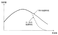
- the constants ka and kb are set so that ka ⁇ kb, that is, in the NBI mode, the enhancement amount for the color difference signal Cb is larger (stronger) than in the WLI mode. . Therefore, an outline of an enhancement characteristic example when the enhancement circuit 48 performs enhancement processing using the above-described enhancement processing coefficient in the WLI mode and the NBI mode is as shown in FIG.
- the enhancement amount is set to be larger than the color difference signals Cr and Cb indicated by the dotted line in the entire frequency region.
- the luminance signal Y and one color difference signal Cb are set to have substantially the same tendency.
- the relative enhancement characteristic of the color difference signal Cb with respect to the luminance signal Y is set to be larger than that in the WLI mode as described above. This state is indicated by a two-dot chain line in FIG.
- the emphasis processing by the emphasis circuit 48 may be configured such that the emphasis characteristics can be changed according to the type of the CCD 29, the color filter 30, and the like via the control circuit 15 in accordance with an operation from the emphasis setting unit in the setting unit 50.
- the endoscope apparatus 1 in the present embodiment having such a configuration includes a color filter 30 as a color separation unit that color-separates and receives and captures the return light of the light irradiated to the subject by the illumination unit.
- the endoscope apparatus 1 stores information for changing the processing content of the enhancement processing unit according to the spectral characteristics of the return light incident on the imaging unit, which differs depending on the type and observation mode of the imaging unit. It has a table 15b as storage means and a control circuit 15 as control means for performing control to change the processing content of the emphasis processing means based on the information of the storage means.
- the surgeon connects the endoscope 2 to the light source device 3 and the video processor 4 and turns on the power, whereby the control circuit 15 of the video processor 4 starts an initial setting process.
- the control circuit 15 sets the light source device 3 and the video processor 4 to the operation mode setting state corresponding to the observation mode in the WLI mode, for example.
- the control circuit 15 may be set to the observation mode instructed by the operator.
- the light source device 3 is set in a state in which the narrow band filter 24 is separated from the illumination optical path as shown by a solid line in FIG.
- the mirror 2 is in a state of taking an image.
- each unit on the video processor 4 side is also set to perform signal processing in the WLI mode.
- the control circuit 15 uses the ID from the ID generation unit 33 to select the type of image pickup means, that is, the type of the CCD 29, and the color filter 30 of the CCD 29 is a single plate complementary color filter. Identify something. Then, as shown in step S3, the control circuit 15 refers to the table 15b using the observation mode and the information on the type of the CCD 30, and sets filter coefficients used when the enhancement circuit 48 performs enhancement processing, that is, Set the emphasis characteristics.
- the enhancement circuit 48 in which the filter coefficients are set in this way has the enhancement characteristic as shown in FIG. As shown in FIG. 4, the luminance signal is set to have a larger enhancement amount than the color difference signal. By setting in this way, when the sharpness is enhanced so that the edge portion of a living tissue or the like becomes clearer, the emphasis characteristic corresponding to the pixel density is set, so that false color and color moire are generated. This can be suppressed and emphasized.
- control circuit 15 refers to the table 15a and sets matrix coefficients for performing matrix calculation by the first matrix circuit 42, the second matrix circuit 46, and the third matrix circuit 49, respectively.
- the video processor 4 performs image processing using the filter coefficient and the matrix coefficient, and passes through the third matrix circuit 49 to output the three primary color signals R, G, B as the image signal of the endoscopic image. Is output to the monitor 5.
- An endoscopic image as an observation image corresponding to this image signal is displayed on the monitor 5. The surgeon performs an endoscopic examination on a tissue to be examined such as an affected part in a body cavity while observing the endoscopic image.
- step S6 the control circuit 15 monitors whether or not a mode switching operation has been performed. If the mode switching operation has not been performed, the process returns to step S5, and the process of displaying the endoscopic image in the WLI mode is continued.
- the surgeon intends to observe the running state of the blood vessels on the surface of the tissue to be examined in more detail, the surgeon operates the mode switch 14.
- the control circuit 15 changes the observation mode of the light source device 3 and the video processor 4 to the setting state of the NBI mode as shown in step S7.
- the control circuit 15 controls the light source device 3 so that the narrowband filter 24 is arranged in the illumination optical path as indicated by a two-dot chain line in FIG. As shown in FIG. 2, the narrow band filter 24 is arranged in the illumination optical path so that the illumination is performed by the narrow band illumination light from the narrow band transmission filter characteristic portions Ga and Ba.
- the control circuit 15 changes the setting of each unit in the video processor 4. Specifically, the control circuit 15 widens the band characteristic of the LPF 41b. Further, the band characteristics of the signal passing of the LPF 41b are widened, and the G color imaged under the G illumination light that is close to the luminance state signal of the traveling state of the capillary blood vessels and the narrow band transmission filter characteristic unit Ga as described above. The resolution (resolution) of the blood vessel running state near the surface layer obtained by the signal is improved.
- the control circuit 15 sets the filter coefficient used in the enhancement process by the enhancement circuit 48 with reference to the table 15b, that is, the enhancement characteristic, according to the change to the NBI mode.
- the enhancement circuit 48 in which the filter coefficients are set in this way has the enhancement characteristic as shown in FIG.
- the luminance signal Y is set to have a larger enhancement amount than the color difference signal Cb as in the case of the WLI mode.
- the signal strength ratio calculation circuit 45 calculates the signal strength ratio t.
- the control circuit 15 refers to the calculated value of the signal strength ratio t and the table 15a, and performs matrix calculation by the first matrix circuit 42, the second matrix circuit 46, and the third matrix circuit 49, respectively.
- the video processor 4 performs image processing using the filter coefficient and the matrix coefficient, and passes through the third matrix circuit 49 to output the three primary color signals R, G, B as the image signal of the endoscopic image. Is output to the monitor 5. An endoscopic image as an observation image corresponding to this image signal is displayed on the monitor 5.
- the third matrix circuit 49 When the display color conversion setting unit 50a is OFF, the third matrix circuit 49 generates color signals R, G, and B as three primary color signals that are not subjected to display color conversion, and the display color conversion setting unit 50 is ON. In this case, the third matrix circuit 49 generates the three primary color signals R, G, and B whose display colors have been converted. While observing this endoscopic image, the operator performs an endoscopic examination in a state where it is easy to identify in detail the running state of capillaries and the like near the surface of the tissue to be examined in the body cavity. In the next step S11, the control circuit 15 monitors whether or not a mode switching operation has been performed. If the mode switching operation has not been performed, the process returns to step S10, and the process of displaying the endoscopic image in the set state of the NBI mode is continued. On the other hand, when the mode switching operation is performed, the process returns to step S1.
- the enhancement circuit 48 can perform enhancement processing while suppressing the occurrence of false colors and color moire. Therefore, according to the present embodiment, it is possible to provide an endoscopic image as a high-quality observation image that is easy for an operator to make a diagnosis or the like. Further, according to the present embodiment, even in the NBI mode, since the signal band of the color difference signal is increased, an endoscopic image with good resolution can be obtained and the running state of capillaries and the like can be made clearer. It can be displayed in a state where it can be easily identified.
- the image signal is generated by the matrix calculation in the third matrix circuit 49 according to the signal intensity ratios t and u of the color signals G1 and B1, so that the color signal G1 , B1 can be converted into a color signal of a luminance signal according to the signal intensity, and the contrast of the endoscopic image in the NBI mode can be prevented from being lowered.
- a narrow band light source device can be easily formed by providing means for inserting / removing the narrow band filter 24 in / from the optical path in addition to the normal white light illumination means.
- the emphasis characteristic by the emphasis circuit 48 is set as shown in FIG. 4, but the emphasis characteristic shown in FIG. 6 may be set as a modification of the emphasis characteristic. good.
- the enhancement characteristic shown in FIG. 6 is set to the enhancement characteristic similar to that shown in FIG. 4 for the luminance signal Y in both the WLI mode and the NBI mode, while the color difference signals Cr and Cb (in the WLI mode).
- the filter coefficient is set so that the frequency characteristic has a small enhancement amount on the high frequency band side where the frequency is high.
- the spectral characteristic of the narrowband filter is trimodal, and further has a narrowband transmission filter characteristic part Ra (center wavelength 600 nm, half width 20 to 40 nm).
- the luminance signal Y and The color difference signals Cb (BY) and Cr (RY) are used as emphasized signals
- the enhancement circuit 48 makes the color difference signals Cb and Cr weaker than the luminance signal Y, and the color enhancement signals Cb and Cr have the same enhancement characteristics.
- the luminance signal Y and the color difference signals Cb and Cr may be enhanced so that
- FIG. 7 shows an overall configuration of an endoscope apparatus 1B according to a first modification of the first embodiment of the present invention.
- a fourth matrix circuit 51 is provided in the preceding stage of the enhancement circuit 48 in the video processor 4 in the first embodiment shown in FIG.
- the fourth matrix circuit 51 reduces the color moire by using the matrix Mat4 for the luminance signal Y and the color difference signals RY and BY output from the enlargement circuit 47 and input to the fourth matrix circuit 51. Matrix calculation for generating highly emphasized signals Y, Cr, and Cb is performed.
- the fourth matrix circuit 51 converts the equation (6) as well as in the WLI mode.
- a matrix Mat4 as shown in equations (7) and (8) is employed.
- Mat3 Mat2 ⁇ 1 in the WLI mode as in the first embodiment (9)
- Mat3 Mat NBI-C- Tf.Mat41 NBI ⁇ 1 (10)
- the matrix Mat41 NBI is [Equation 11] It is represented by
- the matrix elements m11, m12, and m13 are predetermined values.
- the matrix elements m11, m12, and m13 are set based on the signal intensity ratio of R, G, and B in the luminance signal Yh.
- Other configurations are the same as those of the first embodiment.
- an emphasized signal having a high effect of reducing color moiré is generated and the enhancement process is performed by the enhancement circuit 48. Therefore, the color moiré is further reduced as compared with the case of the first embodiment. can do.
- Others have the same operational effects as the first embodiment.
- Mat4 Mat42 NBI / Mat41 NBI ⁇ 1 (12) May be used.
- the matrix Mat3 by the third matrix circuit 49 is the same as in the first embodiment in the WLI mode.
- Mat3 Mat2 ⁇ 1 (14)
- Mat3 Mat NBI-C-Tf ⁇ Mat42 NBI ⁇ 1 (15) Set by.
- the matrix Mat NBI-C-Tf is expressed by the equation (5).
- the matrix Mat42 NBI ⁇ 1 is not limited to the case of the inverse matrix of the Mat42 NBI expressed by the equation (13).
- a pseudo inverse matrix (3 rows and 2 columns) of a matrix (2 rows and 3 columns) composed of the elements of the 1st and 3rd rows of the matrix Mat42 NBI is derived, and the elements of the 1st and 2nd columns are respectively set to the first column.
- a matrix with 3 rows and 3 columns may be used as the elements in the third column (the elements in the second column are all 0).
- This second modification has substantially the same function and effect as the first modification.
- FIG. 8 shows an overall configuration of an endoscope apparatus 1C according to the second embodiment of the present invention.
- the endoscope apparatus 1C includes an endoscope 2C, a light source device 3, a video processor 4C, and a monitor 5.
- a primary color single plate image sensor is employed instead of the complementary color single plate image sensor in the endoscope 2 of FIG. That is, as shown in FIG. 9, a primary color single plate Bayer color filter 30 c is employed on the imaging surface of the CCD 29.
- the color filter 30c is a filter array periodically arranged in the horizontal and vertical directions in units of four filter elements of 2 rows and 2 columns in the horizontal direction and the vertical direction. In this case, R, G and G, B color filter elements are alternately arranged in the horizontal direction and the vertical direction.
- the CCD 29 is driven by a CCD drive circuit 31 as in the first embodiment, for example.
- the video processor 4C in this case is configured such that the output signal of the A / D conversion circuit 34 in the video processor 4 of FIG. 1 is input to the LPF 52 via a switching circuit that switches pixel by pixel (not shown).
- the LPF 52 By passing through the LPF 52, the pixel value of the missing color signal is calculated at each pixel position, and the synchronized three primary color signals R, G, and B are generated.
- the three primary color signals R, G, and B generated through the LPF 52 are subjected to white balance processing by a white balance circuit (abbreviated as WB circuit) 53 and then input to a ⁇ circuit 54 that performs gamma correction.
- WB circuit white balance circuit
- the three primary color signals R, G, and B output from the ⁇ circuit 54 are input to the enlargement circuit 47 and subjected to enlargement processing similarly to the configuration of the video processor 4 in FIG.
- the data is input to an emphasis circuit 48 that performs an emphasis process.
- three primary color signals R, G, B as image signals of an endoscopic image as an observation image are generated by the third matrix circuit 49 and output to the monitor 5.
- the emphasized signals become the three primary color signals R, G, and B, and the enhancement circuit 48 performs enhancement processing on the three primary color signals R, G, and B as the emphasized signals.
- the WLI filter coefficients are stored in the table 15b so that the enhancement amount for G is larger than the enhancement amounts for the other R and B.
- the signals to be enhanced are the three primary color signals (two color signals) G and B, and the enhancement circuit 48 performs enhancement processing on the signals to be emphasized (as color signals) G and B.
- the NBI filter coefficients are stored in the table 15b so that the enhancement amount for G is larger than the enhancement amount for the other B. That is, the table 15b stores the WLI-RB filter coefficient and the WLI-G filter coefficient as the WLI filter coefficient, and also the NBI-B filter coefficient and the NBI-G filter coefficient as the NBI filter coefficient. Stores filter coefficients.
- the WLI-RB filter coefficient and the NBI-B filter coefficient are set to values obtained by multiplying all of the WLI-G filter coefficient and the NBI-G filter coefficient by a constant ka (ka ⁇ 1).
- the common constant ka is set in the WLI mode and the NBI mode.
- the constants ka and kb are set in the WLI mode and the NBI mode as in the first embodiment.
- ka ⁇ kb may be set.
- the third matrix circuit 49 performs a matrix operation in a unit matrix in the WLI mode.
- the third matrix circuit 49 performs a matrix operation using the matrix Mat NBI-C-Tf shown in the above equation (5). That is, when the input / output signals RGB to the third matrix circuit 49 are Rin, Gin, Bin, Rout, Gout, and Bout, respectively, the third matrix circuit 49 performs the following matrix calculation.
- Equation 16 The table 15 a stores matrix coefficients used in the third matrix circuit 49. The operation of this embodiment having such a configuration differs from that of the first embodiment in the emphasized signal, but the basic operation is similar to that of the first embodiment.
- the emphasis circuit 48 of the present embodiment is also set to the emphasis characteristic corresponding to the pixel density, the emphasis process can be performed while suppressing the occurrence of false colors and color moire. Therefore, according to the present embodiment, it is possible to provide an endoscopic image as a high-quality observation image that is easy for an operator to make a diagnosis or the like. Further, according to the present embodiment, no band limitation is performed even in the NBI mode, so that an endoscopic image with a good resolution can be obtained and the running state of capillaries and the like can be displayed in a state that can be more clearly identified. can do.
- the present embodiment it is possible to easily cope with both the WLI mode and the NBI mode by switching a part of processing characteristics in the signal processing system, so that it is very convenient and useful for endoscopy.
- Device In the present embodiment, the case of an image sensor with a primary color single plate has been described. However, an image sensor with two primary colors, that is, an image pickup unit including two image sensors may be employed.
- FIG. 10 shows the configuration of the periphery of the imaging unit at the distal end portion 26 of the endoscope 2C ′ in this case.
- a first CCD 29 a is disposed at the image forming position on the optical axis of the objective lens 28.
- a half mirror 56 that transmits and reflects approximately 50% of incident light is disposed in the middle of the optical axis.
- a second CCD 29b is disposed at the image forming position on the optical axis reflected by the half mirror 56.
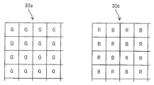
- primary color filters 30a and 30b as shown in FIG. 11 are arranged as color separation units.
- the color filter 30a includes only G as a filter element.
- the color filter 30b is composed of R and B as filter elements.
- An arrangement structure of units for generating color signals for color imaging using both color filters 30a and 30b corresponds to pixels in 2 rows and 2 columns, and a color signal generated from the unit pixels is 4G + 2 (R + B). It becomes.
- the color signal generated from the pixels in 2 rows and 2 columns corresponding to the unit array for generating the color signal is 2G + R + B.
- the first CCD 29 a and the second CCD 29 b are driven by a common CCD drive circuit 31.
- the output signals of the first CCD 29a and the second CCD 29b are converted into baseband signal components by the CDS circuits 32a and 32b, respectively.
- the output signals of the CDS circuits 32a and 32b are subjected to gain adjustment for correcting the characteristics of the half mirror 56 by an amplifier (not shown), added by an adder 57, and input to the A / D conversion circuit 34 shown in FIG. .
- the signal input to the A / D conversion circuit 34 is a signal having a resolution twice that in the case of FIG.
- the processing after the A / D conversion circuit 34 is the same as in FIG. According to this modification, an endoscope image with higher resolution can be generated.
- the other effects are the same as those of the second embodiment.
- the color signal G is replaced with a high frequency instead of the enhancement amount of the color signal R and B (in the WLI mode) or B (in the NBI mode).
- the filter coefficient may be set so that the enhancement amount for the color signal G only on the side is larger than the color signals R and B (in the WLI mode) or B (in the NBI mode).
- the enhancement circuit 48 is configured to perform enhancement processing on the color signals R, G, B (in the WLI mode) or G, B (in the NBI mode).
- the luminance circuit Y and the color difference signals Cr and Cb may be converted into the luminance signal Y and the color difference signals Cr and Cb, and the enhancement circuit 48 may perform an enhancement process.
- FIG. 12 shows an overall configuration of an endoscope apparatus 1D according to the third embodiment of the present invention.
- the endoscope apparatus 1D includes an endoscope 2D, a light source device 3, a video processor 4D, and a monitor 5.
- the endoscope 2D is mounted with an image pickup unit using an image pickup element of three primary colors instead of one image pickup element (an image pickup unit made up of) that is arranged at the distal end portion 26 of the insertion portion 7 in the endoscope 2 of FIG. ing.
- color separation prisms 61a, 61b, and 61c as color separation units for color separation into R, G, and B, and three CCDs 29R, 29G, and 29B disposed at image forming positions, respectively.
- the three CCDs 29R, 29G, and 29B output R, G, and B color signals for each pixel unit. In the present embodiment, this corresponds to an array of units when one pixel performs color imaging.
- signals separated into R, G, and B for each pixel unit are output.
- 12 is not limited to the configuration example of the image pickup unit including the three primary color image pickup elements having the structure shown in FIG. 12, and three plates each having primary color filters for color separation as shown in FIG. An image sensor may be used.
- the CCDs 29R, 29G, and 29B are driven by a common CCD drive circuit 31.
- the output signals from the CCDs 29R, 29G, and 29B are input to a three-system CDS circuit 32 ', and baseband color signals R, G, and B are output from the CDS circuit 32' to an A / D conversion circuit that includes three systems. 34 'and output to the brightness detection circuit 35.
- the processing configuration for the luminance signal Y as the output signal from the RGB-Y / C separation circuit 62 and the color difference signals Cr, Cb and thereafter is the same as the configuration example shown in FIG. However, the emphasis characteristic by the emphasis circuit 48 is different from that in FIG. Also in this embodiment, the filter coefficient to be enhanced by the enhancement circuit 48 is stored in the table 15b.
- WLI-Y / Cr / Cb filter coefficients and NBI-Y / Cb filter coefficients are stored as filter coefficients for emphasis processing stored in the table 15b.
- WLI-Y / Cr The / Cb filter coefficient and the NBI-Y / Cb filter coefficient all store the same value (the NBI-Cr filter coefficient is zero).
- the control circuit 15 refers to the table 15b for each observation mode and sets a filter coefficient to be enhanced by the enhancement circuit 48.
- the table 15a stores matrix coefficients of the first matrix circuit 42, the second matrix circuit 46, and the third matrix circuit 49, as in the first embodiment. Then, the same matrix calculation as in the first embodiment is performed.
- the operation according to the present embodiment has been changed from the case of the image pickup unit made up of a single-plate image pickup device having a complementary color filter in the first embodiment to the image pickup unit made up of an image pickup device of three primary colors. The behavior is similar to the case.
- enhancement processing is performed with the same enhancement characteristics on the luminance signal Y and the color difference signals Cr and Cb corresponding to the three primary color image sensors.
- the enhancement process corresponding to the three primary color image sensors is performed, so that the reproducibility of the blood vessel image and the like by the enhancement process can be improved.
- an image sensor with three primary colors is used, an endoscopic image with higher resolution than in the first embodiment can be obtained.
- the output signal of the A / D conversion circuit 34 ′ in FIG. 12 may be output to the WB circuit 53 in FIG.
- WLI-RGB filter coefficients and NBI-GB filter coefficients are stored as filter coefficients for emphasis processing stored in the table 15b, and WLI-RGB filter coefficients and NBI-GB filters are stored. All the coefficients are stored with the same value (the NBI-R filter coefficient is zero).
- the control circuit 15 refers to the table 15b for each observation mode and sets a filter coefficient to be enhanced by the enhancement circuit 48.
- the table 15a stores the matrix coefficients of the first matrix circuit 42, the second matrix circuit 46, and the third matrix circuit 49, as in the second embodiment. Then, the same matrix calculation as in the second embodiment is performed.
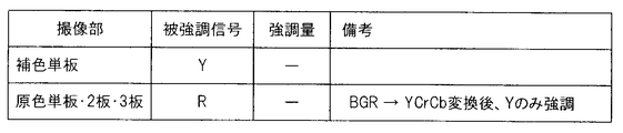
- the image pickup unit displays the signal to be emphasized according to the complementary color single plate, primary color single plate, two plates, and three primary color plates as shown in the column of enhancement amount. Emphasize. Even in this case, it is possible to improve the reproducibility of the biological mucous membrane and reduce the occurrence of false color and color moire, and obtain an endoscopic image that is easy to diagnose.
- the imaging unit is, for example, a primary color single plate or two plates
- enhancement processing is performed on the color signals G and R so that the enhancement amount of the color signal G is larger than the enhancement amount of the color signal R.
- the enhancement circuit 48 makes the enhancement amount of the luminance signal Y larger than the enhancement amount of the color difference signal Cr. Emphasis processing may be performed.
- the image pickup unit is a primary color 3 plate
- the enhancement amount of the color signal G and the enhancement amount of the color signal R are equal to the color signals G and R in the case of the primary color single plate / two plates. To emphasize.
- the enhancement circuit 48 equalizes the enhancement amount of the luminance signal Y and the enhancement amount of the color difference signal Cr.
- the emphasis processing may be performed as described above.
- a filter coefficient in which the enhancement amount is weakened only in the high range may be set. Even in such a case, it is possible to improve the reproducibility of the biological mucous membrane and reduce the occurrence of false colors due to color moire, and obtain an endoscopic image that is easy to diagnose. Further, as a first observation mode in other observation modes, when an endoscopic image as an observation image is generated by imaging reflected light of blue light and fluorescence of red light, as shown in FIG. In addition, the emphasized signal may be emphasized as in the column of enhancement amount according to the complementary color single plate, primary color single plate, two plates, and three plates.
- a complementary color single plate, a primary color single plate, 2 Emphasis may be performed on only one signal to be emphasized Y or B in accordance with the three plates.
- the column of enhancement amount indicating the relationship of the enhancement amount with respect to a plurality of signals to be enhanced is unnecessary, and is indicated by ⁇ .
- a complementary color single plate, primary color single plate, 2 The signal to be emphasized may be emphasized as shown in the column of the amount of enhancement in accordance with the three plates.
- FIG. 18 shows the characteristics of incident light, a signal to be emphasized / a signal for weakening the enhancement amount, and the like for the above-described embodiment as a whole.
- the image capturing unit is a complementary color single plate or a primary color single plate.
- the enhancement amount of the color difference signals Cr and Cb is set to be weakened (relative to the enhancement amount of the luminance signal Y).
- two primary color plates it represents the same as the case of the left complementary color single plate or primary color single plate indicated by ⁇ .
- the signals to be enhanced are the color signals R, G, and B, and in this case, there is no signal that weakens the enhancement amount (in other words, the signals of the R, G, and B signals are set). Set the same amount of emphasis). Other cases are shown in the same notation.
Landscapes
- Life Sciences & Earth Sciences (AREA)
- Health & Medical Sciences (AREA)
- Surgery (AREA)
- Engineering & Computer Science (AREA)
- Biophysics (AREA)
- Medical Informatics (AREA)
- Nuclear Medicine, Radiotherapy & Molecular Imaging (AREA)
- Optics & Photonics (AREA)
- Pathology (AREA)
- Radiology & Medical Imaging (AREA)
- Veterinary Medicine (AREA)
- Biomedical Technology (AREA)
- Heart & Thoracic Surgery (AREA)
- Physics & Mathematics (AREA)
- Molecular Biology (AREA)
- Animal Behavior & Ethology (AREA)
- General Health & Medical Sciences (AREA)
- Public Health (AREA)
- Signal Processing (AREA)
- Endoscopes (AREA)
- Closed-Circuit Television Systems (AREA)
- Instruments For Viewing The Inside Of Hollow Bodies (AREA)
Abstract
Selon l'invention, un dispositif d'endoscope met en image un rayon lumineux renvoyé par un spécimen à étudier éclairé par un moyen d'éclairage, à l'aide d'un dispositif à transfert de charge (DTC) possédant un filtre. Lorsque le degré d'acuité est renforcé par le circuit de renforcement, par rapport au signal de brillance en tant que signal d'image et aux signaux de différence des couleurs R-Y, B-Y, les caractéristiques de renforcement en fonction du type de DTC sont commutées en mode observation et les phénomènes de bruit de couleur et de moirage sont réduits.
Priority Applications (4)
| Application Number | Priority Date | Filing Date | Title |
|---|---|---|---|
| CN201180005842.0A CN102740760B (zh) | 2010-06-28 | 2011-06-07 | 内窥镜装置 |
| EP11800583.4A EP2586359B1 (fr) | 2010-06-28 | 2011-06-07 | Dispositif d'endoscope |
| JP2011548499A JP4996773B2 (ja) | 2010-06-28 | 2011-06-07 | 内視鏡装置 |
| US13/299,863 US8854445B2 (en) | 2010-06-28 | 2011-11-18 | Endoscope apparatus |
Applications Claiming Priority (2)
| Application Number | Priority Date | Filing Date | Title |
|---|---|---|---|
| JP2010-146537 | 2010-06-28 | ||
| JP2010146537 | 2010-06-28 |
Related Child Applications (1)
| Application Number | Title | Priority Date | Filing Date |
|---|---|---|---|
| US13/299,863 Continuation US8854445B2 (en) | 2010-06-28 | 2011-11-18 | Endoscope apparatus |
Publications (1)
| Publication Number | Publication Date |
|---|---|
| WO2012002115A1 true WO2012002115A1 (fr) | 2012-01-05 |
Family
ID=45401845
Family Applications (1)
| Application Number | Title | Priority Date | Filing Date |
|---|---|---|---|
| PCT/JP2011/063064 Ceased WO2012002115A1 (fr) | 2010-06-28 | 2011-06-07 | Dispositif d'endoscope |
Country Status (5)
| Country | Link |
|---|---|
| US (1) | US8854445B2 (fr) |
| EP (1) | EP2586359B1 (fr) |
| JP (1) | JP4996773B2 (fr) |
| CN (1) | CN102740760B (fr) |
| WO (1) | WO2012002115A1 (fr) |
Cited By (6)
| Publication number | Priority date | Publication date | Assignee | Title |
|---|---|---|---|---|
| JP2014103597A (ja) * | 2012-11-21 | 2014-06-05 | Olympus Corp | 撮像装置 |
| JP2015066131A (ja) * | 2013-09-27 | 2015-04-13 | 富士フイルム株式会社 | 内視鏡システム及び光源装置 |
| JP2015091467A (ja) * | 2015-02-12 | 2015-05-14 | 富士フイルム株式会社 | 内視鏡システム |
| CN104936503A (zh) * | 2013-03-25 | 2015-09-23 | 奥林巴斯株式会社 | 内窥镜装置 |
| JP2016214941A (ja) * | 2016-09-12 | 2016-12-22 | 富士フイルム株式会社 | 内視鏡システム及びその作動方法 |
| JP2020512068A (ja) * | 2017-03-09 | 2020-04-23 | クエスト・フォトニック・デバイシーズ・ビー.ブイ.Quest Photonic Devices B.V. | 蛍光イメージングのための医用イメージングヘッドを用いた方法および装置 |
Families Citing this family (18)
| Publication number | Priority date | Publication date | Assignee | Title |
|---|---|---|---|---|
| JP5628062B2 (ja) * | 2011-02-01 | 2014-11-19 | 富士フイルム株式会社 | 電子内視鏡システム |
| JP5178898B1 (ja) * | 2011-10-21 | 2013-04-10 | 株式会社東芝 | 画像信号補正装置、撮像装置、内視鏡装置 |
| JP5925169B2 (ja) | 2013-09-27 | 2016-05-25 | 富士フイルム株式会社 | 内視鏡システム及びその作動方法並びに内視鏡用光源装置 |
| JP6008812B2 (ja) * | 2013-09-27 | 2016-10-19 | 富士フイルム株式会社 | 内視鏡システム及びその作動方法 |
| JP5820960B1 (ja) * | 2013-12-06 | 2015-11-24 | オリンパス株式会社 | 撮像装置、撮像装置の作動方法 |
| JP5932188B1 (ja) * | 2014-07-29 | 2016-06-08 | オリンパス株式会社 | 内視鏡のためのビデオプロセッサ及びそれを備えた内視鏡システム |
| DE112015005595T5 (de) * | 2015-01-20 | 2017-09-28 | Olympus Corporation | Bildverabeitungsvorrichtung, Verfahren zum Bedienen der Bildverarbeitungsvorrichtung, Programm zum Bedienen der Bildverarbeitungsvorrichtung und Endoskopvorrichtung |
| JP6639920B2 (ja) * | 2016-01-15 | 2020-02-05 | ソニー・オリンパスメディカルソリューションズ株式会社 | 医療用信号処理装置、及び医療用観察システム |
| JP6654051B2 (ja) * | 2016-01-15 | 2020-02-26 | ソニー・オリンパスメディカルソリューションズ株式会社 | 医療用観察システム |
| JP6826455B2 (ja) * | 2017-02-14 | 2021-02-03 | 株式会社日立製作所 | 画像形成装置 |
| JP7235540B2 (ja) * | 2019-03-07 | 2023-03-08 | ソニー・オリンパスメディカルソリューションズ株式会社 | 医療用画像処理装置及び医療用観察システム |
| DE102019123356B4 (de) * | 2019-08-30 | 2025-02-27 | Schölly Fiberoptic GmbH | Sensoranordnung, Verfahren zur Berechnung eines Farbbildes und eines hyperspektralen Bildes, Verfahren zur Durchführung eines Weißabgleichs und Verwendung der Sensoranordnung in der medizinischen Bildgebung |
| TWI754863B (zh) * | 2019-11-29 | 2022-02-11 | 聯陽半導體股份有限公司 | 影像擷取裝置及方法 |
| US12178389B2 (en) * | 2020-03-05 | 2024-12-31 | Stryker Corporation | Systems and methods for endoscope type detection |
| US12089802B2 (en) * | 2020-03-17 | 2024-09-17 | Sony Olympus Medical Solutions Inc. | Medical image processing apparatus and medical observation system |
| JP7503019B2 (ja) * | 2021-03-31 | 2024-06-19 | Hoya株式会社 | 電子内視鏡用プロセッサ及び電子内視鏡システム |
| US12239409B2 (en) | 2022-02-28 | 2025-03-04 | Visionsense Ltd. | Fluorescence imaging camera assembly for open surgery |
| JP2024137021A (ja) * | 2023-03-24 | 2024-10-04 | ソニー・オリンパスメディカルソリューションズ株式会社 | 医療用画像処理装置及び制御方法 |
Citations (8)
| Publication number | Priority date | Publication date | Assignee | Title |
|---|---|---|---|---|
| JPH02271822A (ja) * | 1989-04-13 | 1990-11-06 | Olympus Optical Co Ltd | 内視鏡用ビデオプロセッサ |
| JPH049626B2 (fr) | 1983-10-25 | 1992-02-20 | ||
| JPH06339458A (ja) * | 1993-06-01 | 1994-12-13 | Olympus Optical Co Ltd | 内視鏡装置 |
| JP2006061621A (ja) | 2004-08-30 | 2006-03-09 | Olympus Corp | 内視鏡用調光信号生成装置 |
| JP2006061620A (ja) * | 2004-08-30 | 2006-03-09 | Olympus Corp | 内視鏡用映像信号処理装置 |
| JP2006068321A (ja) * | 2004-09-02 | 2006-03-16 | Olympus Corp | 内視鏡装置 |
| JP2007300972A (ja) * | 2006-05-08 | 2007-11-22 | Olympus Medical Systems Corp | 内視鏡用画像処理装置 |
| JP2008086605A (ja) * | 2006-10-03 | 2008-04-17 | Pentax Corp | 内視鏡プロセッサ、自家蛍光画像表示プログラム、及び内視鏡システム |
Family Cites Families (6)
| Publication number | Priority date | Publication date | Assignee | Title |
|---|---|---|---|---|
| US4885633A (en) * | 1988-06-13 | 1989-12-05 | The United States Of America As Represented By The Administrator Of The National Aeronautics And Space Administration | Quantitative surface temperature measurement using two-color thermographic phosphors and video equipment |
| KR100961591B1 (ko) * | 2004-08-30 | 2010-06-04 | 올림푸스 가부시키가이샤 | 내시경 장치 |
| JP4732769B2 (ja) * | 2005-03-04 | 2011-07-27 | 富士フイルム株式会社 | 内視鏡装置 |
| JP5179035B2 (ja) * | 2005-09-30 | 2013-04-10 | Hoya株式会社 | 電子内視鏡装置 |
| CN101536329A (zh) * | 2005-10-21 | 2009-09-16 | 阿密蒙有限公司 | 用于视频的未压缩无线传输的装置和方法 |
| US7860180B2 (en) * | 2005-10-21 | 2010-12-28 | Amimon Ltd | OFDM modem for transmission of continuous complex numbers |
-
2011
- 2011-06-07 JP JP2011548499A patent/JP4996773B2/ja active Active
- 2011-06-07 CN CN201180005842.0A patent/CN102740760B/zh active Active
- 2011-06-07 WO PCT/JP2011/063064 patent/WO2012002115A1/fr not_active Ceased
- 2011-06-07 EP EP11800583.4A patent/EP2586359B1/fr active Active
- 2011-11-18 US US13/299,863 patent/US8854445B2/en active Active
Patent Citations (8)
| Publication number | Priority date | Publication date | Assignee | Title |
|---|---|---|---|---|
| JPH049626B2 (fr) | 1983-10-25 | 1992-02-20 | ||
| JPH02271822A (ja) * | 1989-04-13 | 1990-11-06 | Olympus Optical Co Ltd | 内視鏡用ビデオプロセッサ |
| JPH06339458A (ja) * | 1993-06-01 | 1994-12-13 | Olympus Optical Co Ltd | 内視鏡装置 |
| JP2006061621A (ja) | 2004-08-30 | 2006-03-09 | Olympus Corp | 内視鏡用調光信号生成装置 |
| JP2006061620A (ja) * | 2004-08-30 | 2006-03-09 | Olympus Corp | 内視鏡用映像信号処理装置 |
| JP2006068321A (ja) * | 2004-09-02 | 2006-03-16 | Olympus Corp | 内視鏡装置 |
| JP2007300972A (ja) * | 2006-05-08 | 2007-11-22 | Olympus Medical Systems Corp | 内視鏡用画像処理装置 |
| JP2008086605A (ja) * | 2006-10-03 | 2008-04-17 | Pentax Corp | 内視鏡プロセッサ、自家蛍光画像表示プログラム、及び内視鏡システム |
Non-Patent Citations (1)
| Title |
|---|
| See also references of EP2586359A4 |
Cited By (8)
| Publication number | Priority date | Publication date | Assignee | Title |
|---|---|---|---|---|
| JP2014103597A (ja) * | 2012-11-21 | 2014-06-05 | Olympus Corp | 撮像装置 |
| CN104936503A (zh) * | 2013-03-25 | 2015-09-23 | 奥林巴斯株式会社 | 内窥镜装置 |
| CN104936503B (zh) * | 2013-03-25 | 2016-10-26 | 奥林巴斯株式会社 | 内窥镜装置 |
| JP2015066131A (ja) * | 2013-09-27 | 2015-04-13 | 富士フイルム株式会社 | 内視鏡システム及び光源装置 |
| JP2015091467A (ja) * | 2015-02-12 | 2015-05-14 | 富士フイルム株式会社 | 内視鏡システム |
| JP2016214941A (ja) * | 2016-09-12 | 2016-12-22 | 富士フイルム株式会社 | 内視鏡システム及びその作動方法 |
| JP2020512068A (ja) * | 2017-03-09 | 2020-04-23 | クエスト・フォトニック・デバイシーズ・ビー.ブイ.Quest Photonic Devices B.V. | 蛍光イメージングのための医用イメージングヘッドを用いた方法および装置 |
| JP7102432B2 (ja) | 2017-03-09 | 2022-07-19 | クエスト・フォトニック・デバイシーズ・ビー.ブイ. | 蛍光イメージングのための医用イメージングヘッドを用いた方法および装置 |
Also Published As
| Publication number | Publication date |
|---|---|
| US8854445B2 (en) | 2014-10-07 |
| CN102740760B (zh) | 2015-05-20 |
| EP2586359A4 (fr) | 2017-07-05 |
| JPWO2012002115A1 (ja) | 2013-08-22 |
| CN102740760A (zh) | 2012-10-17 |
| EP2586359B1 (fr) | 2018-12-05 |
| JP4996773B2 (ja) | 2012-08-08 |
| US20120127292A1 (en) | 2012-05-24 |
| EP2586359A1 (fr) | 2013-05-01 |
Similar Documents
| Publication | Publication Date | Title |
|---|---|---|
| JP4996773B2 (ja) | 内視鏡装置 | |
| JP4009626B2 (ja) | 内視鏡用映像信号処理装置 | |
| JP5143293B2 (ja) | 内視鏡装置 | |
| JP4891990B2 (ja) | 内視鏡装置 | |
| US8237783B2 (en) | Image processing device for endoscope and endoscope apparatus | |
| US8773522B2 (en) | Endoscope apparatus | |
| JP5308815B2 (ja) | 生体観測システム | |
| EP3117759B1 (fr) | Système d'endoscope | |
| WO2013042396A1 (fr) | Instrument médical | |
| JP5041936B2 (ja) | 生体観測装置 | |
| JP3958761B2 (ja) | 内視鏡用調光信号生成装置 |
Legal Events
| Date | Code | Title | Description |
|---|---|---|---|
| WWE | Wipo information: entry into national phase |
Ref document number: 201180005842.0 Country of ref document: CN |
|
| WWE | Wipo information: entry into national phase |
Ref document number: 2011548499 Country of ref document: JP |
|
| 121 | Ep: the epo has been informed by wipo that ep was designated in this application |
Ref document number: 11800583 Country of ref document: EP Kind code of ref document: A1 |
|
| WWE | Wipo information: entry into national phase |
Ref document number: 2011800583 Country of ref document: EP |
|
| NENP | Non-entry into the national phase |
Ref country code: DE |