WO2012002204A1 - Distributeur pour mousse et liquide - Google Patents
Distributeur pour mousse et liquide Download PDFInfo
- Publication number
- WO2012002204A1 WO2012002204A1 PCT/JP2011/064222 JP2011064222W WO2012002204A1 WO 2012002204 A1 WO2012002204 A1 WO 2012002204A1 JP 2011064222 W JP2011064222 W JP 2011064222W WO 2012002204 A1 WO2012002204 A1 WO 2012002204A1
- Authority
- WO
- WIPO (PCT)
- Prior art keywords
- liquid
- dispenser
- passage
- foaming chamber
- conduit
- Prior art date
- Legal status (The legal status is an assumption and is not a legal conclusion. Google has not performed a legal analysis and makes no representation as to the accuracy of the status listed.)
- Ceased
Links
Images





Classifications
-
- B—PERFORMING OPERATIONS; TRANSPORTING
- B65—CONVEYING; PACKING; STORING; HANDLING THIN OR FILAMENTARY MATERIAL
- B65D—CONTAINERS FOR STORAGE OR TRANSPORT OF ARTICLES OR MATERIALS, e.g. BAGS, BARRELS, BOTTLES, BOXES, CANS, CARTONS, CRATES, DRUMS, JARS, TANKS, HOPPERS, FORWARDING CONTAINERS; ACCESSORIES, CLOSURES, OR FITTINGS THEREFOR; PACKAGING ELEMENTS; PACKAGES
- B65D47/00—Closures with filling and discharging, or with discharging, devices
- B65D47/04—Closures with discharging devices other than pumps
- B65D47/06—Closures with discharging devices other than pumps with pouring spouts or tubes; with discharge nozzles or passages
-
- B—PERFORMING OPERATIONS; TRANSPORTING
- B05—SPRAYING OR ATOMISING IN GENERAL; APPLYING FLUENT MATERIALS TO SURFACES, IN GENERAL
- B05B—SPRAYING APPARATUS; ATOMISING APPARATUS; NOZZLES
- B05B7/00—Spraying apparatus for discharge of liquids or other fluent materials from two or more sources, e.g. of liquid and air, of powder and gas
- B05B7/0018—Spraying apparatus for discharge of liquids or other fluent materials from two or more sources, e.g. of liquid and air, of powder and gas with devices for making foam
- B05B7/0025—Spraying apparatus for discharge of liquids or other fluent materials from two or more sources, e.g. of liquid and air, of powder and gas with devices for making foam with a compressed gas supply
- B05B7/0031—Spraying apparatus for discharge of liquids or other fluent materials from two or more sources, e.g. of liquid and air, of powder and gas with devices for making foam with a compressed gas supply with disturbing means promoting mixing, e.g. balls, crowns
- B05B7/0037—Spraying apparatus for discharge of liquids or other fluent materials from two or more sources, e.g. of liquid and air, of powder and gas with devices for making foam with a compressed gas supply with disturbing means promoting mixing, e.g. balls, crowns including sieves, porous members or the like
-
- B—PERFORMING OPERATIONS; TRANSPORTING
- B05—SPRAYING OR ATOMISING IN GENERAL; APPLYING FLUENT MATERIALS TO SURFACES, IN GENERAL
- B05B—SPRAYING APPARATUS; ATOMISING APPARATUS; NOZZLES
- B05B11/00—Single-unit hand-held apparatus in which flow of contents is produced by the muscular force of the operator at the moment of use
- B05B11/0005—Components or details
- B05B11/0059—Components or details allowing operation in any orientation, e.g. for discharge in inverted position
-
- B—PERFORMING OPERATIONS; TRANSPORTING
- B05—SPRAYING OR ATOMISING IN GENERAL; APPLYING FLUENT MATERIALS TO SURFACES, IN GENERAL
- B05B—SPRAYING APPARATUS; ATOMISING APPARATUS; NOZZLES
- B05B11/00—Single-unit hand-held apparatus in which flow of contents is produced by the muscular force of the operator at the moment of use
- B05B11/01—Single-unit hand-held apparatus in which flow of contents is produced by the muscular force of the operator at the moment of use characterised by the means producing the flow
- B05B11/02—Membranes or pistons acting on the contents inside the container, e.g. follower pistons
- B05B11/026—Membranes separating the content remaining in the container from the atmospheric air to compensate underpressure inside the container
-
- B—PERFORMING OPERATIONS; TRANSPORTING
- B05—SPRAYING OR ATOMISING IN GENERAL; APPLYING FLUENT MATERIALS TO SURFACES, IN GENERAL
- B05B—SPRAYING APPARATUS; ATOMISING APPARATUS; NOZZLES
- B05B11/00—Single-unit hand-held apparatus in which flow of contents is produced by the muscular force of the operator at the moment of use
- B05B11/01—Single-unit hand-held apparatus in which flow of contents is produced by the muscular force of the operator at the moment of use characterised by the means producing the flow
- B05B11/04—Deformable containers producing the flow, e.g. squeeze bottles
-
- B—PERFORMING OPERATIONS; TRANSPORTING
- B05—SPRAYING OR ATOMISING IN GENERAL; APPLYING FLUENT MATERIALS TO SURFACES, IN GENERAL
- B05B—SPRAYING APPARATUS; ATOMISING APPARATUS; NOZZLES
- B05B11/00—Single-unit hand-held apparatus in which flow of contents is produced by the muscular force of the operator at the moment of use
- B05B11/01—Single-unit hand-held apparatus in which flow of contents is produced by the muscular force of the operator at the moment of use characterised by the means producing the flow
- B05B11/04—Deformable containers producing the flow, e.g. squeeze bottles
- B05B11/047—Deformable containers producing the flow, e.g. squeeze bottles characterised by the outlet or venting means
-
- G—PHYSICS
- G02—OPTICS
- G02C—SPECTACLES; SUNGLASSES OR GOGGLES INSOFAR AS THEY HAVE THE SAME FEATURES AS SPECTACLES; CONTACT LENSES
- G02C13/00—Assembling; Repairing; Cleaning
- G02C13/008—Devices specially adapted for cleaning contact lenses
-
- A—HUMAN NECESSITIES
- A61—MEDICAL OR VETERINARY SCIENCE; HYGIENE
- A61L—METHODS OR APPARATUS FOR STERILISING MATERIALS OR OBJECTS IN GENERAL; DISINFECTION, STERILISATION OR DEODORISATION OF AIR; CHEMICAL ASPECTS OF BANDAGES, DRESSINGS, ABSORBENT PADS OR SURGICAL ARTICLES; MATERIALS FOR BANDAGES, DRESSINGS, ABSORBENT PADS OR SURGICAL ARTICLES
- A61L12/00—Methods or apparatus for disinfecting or sterilising contact lenses; Accessories therefor
- A61L12/08—Methods or apparatus for disinfecting or sterilising contact lenses; Accessories therefor using chemical substances
-
- B—PERFORMING OPERATIONS; TRANSPORTING
- B05—SPRAYING OR ATOMISING IN GENERAL; APPLYING FLUENT MATERIALS TO SURFACES, IN GENERAL
- B05B—SPRAYING APPARATUS; ATOMISING APPARATUS; NOZZLES
- B05B1/00—Nozzles, spray heads or other outlets, with or without auxiliary devices such as valves, heating means
- B05B1/14—Nozzles, spray heads or other outlets, with or without auxiliary devices such as valves, heating means with multiple outlet openings; with strainers in or outside the outlet opening
- B05B1/16—Nozzles, spray heads or other outlets, with or without auxiliary devices such as valves, heating means with multiple outlet openings; with strainers in or outside the outlet opening having selectively- effective outlets
-
- B—PERFORMING OPERATIONS; TRANSPORTING
- B05—SPRAYING OR ATOMISING IN GENERAL; APPLYING FLUENT MATERIALS TO SURFACES, IN GENERAL
- B05B—SPRAYING APPARATUS; ATOMISING APPARATUS; NOZZLES
- B05B7/00—Spraying apparatus for discharge of liquids or other fluent materials from two or more sources, e.g. of liquid and air, of powder and gas
- B05B7/0018—Spraying apparatus for discharge of liquids or other fluent materials from two or more sources, e.g. of liquid and air, of powder and gas with devices for making foam
-
- B—PERFORMING OPERATIONS; TRANSPORTING
- B05—SPRAYING OR ATOMISING IN GENERAL; APPLYING FLUENT MATERIALS TO SURFACES, IN GENERAL
- B05B—SPRAYING APPARATUS; ATOMISING APPARATUS; NOZZLES
- B05B7/00—Spraying apparatus for discharge of liquids or other fluent materials from two or more sources, e.g. of liquid and air, of powder and gas
- B05B7/02—Spray pistols; Apparatus for discharge
- B05B7/04—Spray pistols; Apparatus for discharge with arrangements for mixing liquids or other fluent materials before discharge
- B05B7/0416—Spray pistols; Apparatus for discharge with arrangements for mixing liquids or other fluent materials before discharge with arrangements for mixing one gas and one liquid
Definitions
- the present invention relates to a dispenser that can be attached to an opening of a squeeze bottle that inverts a bottle and discharges a liquid content, and discharges a straight liquid and a foam liquid, respectively.
- the present invention relates to a dispenser that can switch the discharge between a straight liquid and a foam liquid.
- the present invention relates to a method of using the dispenser for cleaning and storing contact lenses.
- Liquid agents containing surfactants such as hand soap, body soap, shampoo, dishwashing liquid, or contact lens cleaning liquid are stored in a predetermined container and distributed in the market.
- Such a liquid agent is basically made into a foam state by the action of a surfactant contained in the cleaning liquid. Then, the oily soil is removed without damaging the object to be cleaned with the foam. That is, it is foamy at the time of washing operation, but is liquid at the time of distribution or storage. Therefore, some proposals have been made on the container so that it can be supplied in a bubble state from the container discharge port in consideration of the convenience of the user.
- Patent Document 2 An injection pump is attached to the mouth of a bottle-shaped container, and when in use, the spout of the injection pump is pushed down and released to suck up the liquid content into the liquid chamber and eject it from the spout outlet to the outside.
- Patent Document 3 Proposal relating to a discharge mode switching device for a trigger type pump dispenser that can switch all discharge modes of straight flow, vortex flow, and bubbles and that does not cause any disturbance in each discharge flow.
- Patent Document 3 Proposal of a trigger type liquid dispensing device that facilitates positioning of a nozzle cap by touching with a fingertip, visual color or pattern when selecting a desired ejection state of an ejection nozzle
- trigger-type ejection mechanisms are convenient for the user and are preferable in terms of environmental problems compared to aerosol containers.
- the trigger type nozzle has a problem to be solved in terms of its structural complexity, and is a factor that raises the ratio of the cost of containers etc. to the overall price even though the sales purpose is liquid. Can also be.
- the proposal is common in that it has a ball-shaped valve body on the liquid flow path, and the liquid that is ejected when the container is upright and inverted, and the structure is simple compared to the trigger type. Yes.
- the discharge of the foam / liquid is performed by erecting and inverting the container, there is an advantage that the selection of the foam / liquid is clear.
- the user is required to handle the container in a different direction and method, and on the other hand, it can be detrimental to the feeling of use.
- bubbles cannot be accurately placed on the lens if bubbles are put out in an upright state.
- Non-Patent Document 1 “Characteristics of Former Containers and Recent Technology Trends” includes “Non-Gas as consumers' awareness of safety and resource saving increases.
- This type of former container referring to the trigger type or squeeze bottle
- This type of former container is easy to use, and can be said to be a container that fits the current era.
- JP-T-3-503380 Japanese Patent Laid-Open No. 11-114461 JP-A-8-252508 JP 2000-246154 A Japanese Utility Model Publication No. 2-102366 JP 2008-155986 A
- the dispenser attached to the opening of the squeeze bottle has a first flow path for discharging straight liquid and a second flow path for discharging foamy liquid.
- each of the flow paths has the following configuration.
- the first flow path has a first consistent passage that connects the first inlet and the first outlet for the content liquid.
- the second channel has an opening at the bottom inside the bottle and has a pipe with an inner diameter of 0.8 to 4 mm, which is an air supply channel extending to the foaming chamber.
- a second through passage connecting the second discharge port from the foaming chamber, and the second inlet of the content liquid to the conduit has an inner diameter of 0.06 to 2 mm in the proximal portion of the foaming chamber It has been drilled.
- a straight liquid refers to a liquid in which the portion of foam occupies a volume of about 30% or less when the liquid supplied from the discharge port is poured into another container, for example, and does not necessarily contain any bubbles. It does not point to. Moreover, the liquid discharged
- the foamy liquid refers to a liquid in which the foam portion occupies a volume of about 70% or more of the whole, and does not necessarily mean that the foam is 100%.
- the first flow path is a through-passage that is not particularly obstructed in order to supply the content liquid without foaming.
- the second flow path has a conduit having a length that reaches the bottom of the bottle as an air intake in order to mix and foam air with the liquid.
- the present invention is a dispenser attached to a squeeze bottle, and when the content liquid is taken out, the bottle is turned upside down. At that time, air collects at the bottom of the bottle.
- the conduit is provided to supply this air to the foaming chamber.
- a second inlet for the content liquid is formed in front of the foaming chamber in order to simultaneously supply the content liquid into the foaming chamber.
- the discharge ports of the first channel and the second channel are provided with caps that close the respective ports, so that the straight liquid and the foam liquid can be used properly according to the purpose of the user.
- the system which switches discharge by opening / closing of each flow path instead of the presence or absence of a cap may be used.
- the dispenser includes a hollow support member in which the first and second flow paths are separately formed, and a rotation member that is rotatably supported inside the hollow of the support member, It is preferable that at least a part of the first consistent passage and the foaming chamber are provided independently on the rotating member.
- the foaming chamber when the first integrated passage communicates with the first discharge port (that is, when the first flow path communicates) by rotating the rotating member at a predetermined angle, the foaming chamber is connected to the conduit or It is blocked from the second through path (that is, the second flow path is blocked).
- the conduit, the foaming chamber, and the second through passage communicate with each other (that is, when the second flow path communicates)
- the first integrated passage is blocked (that is, the first flow path is blocked).
- the discharge port can be shared in the case of the switching method.
- the first integrated passage when a part of the first integrated passage provided in the rotating member is a third through passage, the first integrated passage includes a second through passage and a third through passage.
- the second through path is shared by the second flow path and the first flow path.
- the dispenser structure can be made simpler by sharing the second through path connected to the discharge port with the first flow path and the second flow path.
- the ratio of the inner diameter of the second inlet to the inner diameter of the conduit at the position where the air and the content liquid merge is 1/50 to 40/50.
- the air and the content liquid are mixed efficiently, and a soft and smooth bubble can be formed.
- the inner diameter of the conduit is preferably reduced to about 1/5 to 4/5 immediately before communicating with the second inlet, so that the liquid from the second inlet can easily entrain air. .
- the foaming chamber is a hollow tube having openings on the discharge port side and the inflow port side, and the openings of the hollow tube are each covered with a screen filter.
- the mesh of the screen filter is set to be coarser on the inlet side than on the outlet side. This is because the foaming effect is further improved by adopting such a structure.
- the contact lens can be stored in a contact lens storage container filled with a straight liquid by washing the contact lens with the foam liquid discharged using the dispenser having the above structure.
- the dispenser of the present invention has a simple structure and can be manufactured at low cost without requiring special equipment. Moreover, it can apply to a squeeze-type bottle opening part, and can eject the liquid of a foaming state and a straight-ahead state according to a use, respectively. After the bottle content liquid is used, the dispenser can be removed and filled with the content liquid, or it can be re-applied to a replacement bottle and used repeatedly, thereby providing an environmentally friendly dispenser.
- this dispenser is suitable for applications where it is assumed that the same solution is used in two forms, a foamed state and a straight-ahead state. Specifically, it is easy to use by being used for cleaning and storing contact lenses. We can propose good care methods.
- FIG. 1 is a cross-sectional view showing an embodiment of the dispenser of the present invention.
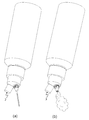
- FIG. 2 is a diagram showing (a) straight liquid and (b) foam liquid discharge.
- FIG. 3 is a cross-sectional view showing a portion where air and content liquid meet.
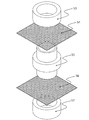
- FIG. 4 is an exploded view showing an example of a foaming chamber.
- FIG. 5 is a cross-sectional view showing another embodiment of the dispenser of the present invention.
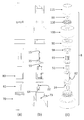
- FIG. 6 is an exploded view of an example of the dispenser of the present invention, (a) a front view, (b) a sectional view, and (c) a perspective view.
- FIG. 1 is a cross-sectional view showing an embodiment of the dispenser of the present invention.
- FIG. 2 is a diagram showing (a) straight liquid and (b) foam liquid discharge.
- FIG. 3 is a cross-sectional view showing a portion where air and content liquid meet.
- FIG. 4 is an exploded view showing an example of a foaming chamber.
- FIG. 7 is a diagram showing a disassembled state of another example of the dispenser of the present invention, (a) a front view, (b) a sectional view, and (c) a perspective view.
- FIG. 8 shows a state in which an example of a dispenser of the present invention is used in a contact lens solution, and is a schematic diagram showing (a) when a lens is washed and (b) when a lens is stored.
- FIG. 1 schematically shows a longitudinal section of one embodiment of the dispenser 1 of the present invention.
- a first discharge port 10 is formed on the upper right side of the drawing, and a second discharge port 11 is formed on the upper left side.
- the first inflow port 20 of the content liquid communicates with the first discharge port 10, and the first consistent passage 30 extends.
- the first flow path for discharging the straight liquid is composed of a first inlet, a first consistent passage, and a first outlet.
- the first consistent passage is shown bent in a dogleg shape, but it may extend linearly from the first inlet 20 toward the first outlet 10.
- the horizontal cross-sectional shape of the first integrated passage may be not only a circle or an ellipse but also a polygon.
- the inner diameter is 0.5 to 2.0 mm and may be constant over the entire length, or may be narrower as the inlet 20 side widens toward the outlet 10 or vice versa. If the discharge port 10 side is narrowed, the content liquid can be discharged vigorously, and it is easy to aim when pouring the liquid into another container.
- a conduit 40 having a length reaching the bottom of the bottle and an air supply port 41 and connecting to the foaming chamber 50 is shown.
- a second inlet 21 for the content liquid is formed in the proximal portion of the foaming chamber 50.
- the conduit 40 and the foaming chamber 50 are connected via the connecting pipe 60, but the conduit and the foaming chamber may be directly connected without using the connecting pipe.
- the 2nd inflow port 21 is formed in the connection pipe 60, this may be formed in the conduit
- any structure that feeds both air and content liquid into the foaming chamber may be used.
- the second inlet is separated from the proximal portion of the foaming chamber (more specifically, within a range of 0.4 to 2.0 mm). And it is preferably formed.
- the inner diameter of the conduit is generally 0.8 to 4 mm and may be appropriately designed.
- the liquid initially poured out may not be in the form of a suitable foam because the liquid held in the conduit is discharged as it is. is there. Further, if the diameter is made smaller than the above range, the content liquid component may be dried and clogged in the middle of the conduit.
- the shape and inner diameter of the horizontal cross section of the conduit are the same as those of the first integrated passage, and do not necessarily have the same diameter over the entire length.
- the conduit preferably has an appropriate shape retaining property that does not easily be bent by its own weight.
- it is made of a material such as polyethylene, polypropylene, silicon, nylon, polystyrene, or polyvinyl chloride, preferably polyethylene, polypropylene, or silicon.
- the shape of the supply port 41 is good to have the shape cut
- the second inlet is drilled with an inner diameter of 0.06 to 2 mm.
- the mixing ratio of air and liquid is susceptible to the ratio of the inner diameter of the second inlet to the inner diameter of the conduit. Therefore, in order to obtain a desired bubble state, the ratio with the inner diameter of the conduit may be adjusted as appropriate.
- the ratio of the inner diameter of the second inlet to the inner diameter of the conduit at the position where the air and the content liquid merge is preferably 1/50 to 40/50, more preferably 1/20 to 2/3. Is more preferable, and 1/10 to 5/10 is most preferable.
- the liquid that has entered the connecting pipe 60 from the second inlet 21 is mixed in such a way that it once travels in parallel with the air flow and merges perpendicularly to the air flow just before the foaming chamber.
- Such a merging method is not necessarily limited to the one shown in the figure, and may be mixed with air vertically (see FIG. 3) immediately after entering the connecting pipe, or with a predetermined flow rate.
- the liquid contents may be joined at an angle.
- the conduit 40 is connected to the foaming chamber 50 via a connecting pipe 60.
- the foaming chamber 50 is shown as a cavity in which a mesh filter is stretched on the side 58 (hereinafter referred to as the inflow side) where the content liquid and air enter, and the side 52 where the foamed liquid is discharged (hereinafter referred to as the discharge port side).
- the foaming means is not particularly limited, and for example, a sponge having a through hole or a hollow fiber may be disposed in the foaming chamber.
- the mesh filter mesh is not shown in FIG. 1, it is preferable to make the mesh on the inlet side rougher than the mesh on the outlet side. More specifically, it is preferable that the outlet side is 100 to 300 mesh and the opening is 200 to 40 ⁇ m, the inlet side is 75 to 250 mesh and the opening is 300 to 50 ⁇ m.
- the foaming chamber 50 shown in FIG. 1 has a structure as shown in FIG. In FIG. 4, from above, an annular ring 53 on the discharge port side 52, a mesh filter 54 having a mesh 200 opening of 82 ⁇ m, a tubular foaming chamber main body 55 having a diameter inserted vertically into the annular ring, and a mesh 100 opening having a mesh opening of 183 ⁇ m
- the foaming chamber 50 having a cavity whose upper and lower sides are covered with a mesh filter is formed.
- the material of the mesh filter is polyester, nylon, polypropylene, polyethylene, Teflon (registered trademark), etc., preferably polyester or nylon.
- a second through passage 31 communicating with the second discharge port 11 is formed on the foaming chamber 50.
- the second through passage 31 is a through passage having a diameter larger than that of the first integrated passage 30 and allows the foamed liquid discharged from the foaming chamber 50 to pass smoothly.
- the inner diameter of this through passage is about 1.5 to 4.5 mm.
- the second flow path includes a conduit 40, a connecting pipe 60 having a second inlet 21, a foaming chamber 50, a second through-passage 31, and a second discharge port 11, and a foam liquid ( It can be seen that (see FIG. 2B) can be discharged. As shown in FIG. 2, by moving the caps 2 and 3 that close the discharge ports respectively, it is possible to properly use the straight liquid and the foam liquid depending on the purpose.
- FIG. 6 is a view showing the arrangement before assembling the dispenser of FIG.
- the explanation will be made together with the structure of each part of this example based on FIG. 6 including the operation method.
- a support member 70 that becomes the main body of the dispenser 5.
- the support member 70 includes a screw 71 screwed into the squeeze bottle opening on the lower inner peripheral surface, an inner peripheral rib 72 for holding the connecting member 61 connected to the conduit 42 inside the support member, and a foaming chamber above the rib.
- 51 has a space 73 that accommodates a rotating member 80 that houses interior 51 and the like, and a component presser 90 for screwing together with a component presser 90 for setting each component on a support member.
- the connecting member 61 is connected by the insertion portion 62 being inserted into the conduit 42, and the rotating member 80 is slidably mounted on the upper plate 63.
- An air passage 64 for sending air through the conduit is formed in the insertion portion 62 through the connecting member, and a second inlet 22 is formed so as to be orthogonal to the air passage.
- the first inlet 23 is formed as a hole that penetrates the upper plate 63. This hole further forms a part of the first flow path of the straight liquid by aligning linearly with the groove 82 formed on the side surface of the rotating member 80 (as a part of the first consistent passage).
- Rotating member 80 includes foam chamber 51 in hollow interior 83 and supports the foam chamber by bottom 84. Further, the hollow portion 83 has a hole 85 for allowing air and liquid to pass therethrough so as to coincide with the opening 65 of the air passage 64 formed in the upper plate 63 of the connecting member 61 at a predetermined position. Therefore, when the groove 82 is aligned with the position of the hole from the first inflow port 23 by rotating the rotating member to a predetermined position, the first consistent passage is communicated. On the other hand, when the holes 85 and the opening 65 of the upper plate are aligned, the foaming chamber 51 communicates with the conduit 42 and the air and the content liquid fed through the conduit etc. are introduced into the foaming chamber 51. .
- a notch groove 86 that is engaged with two ribs 92 formed in the lower portion of the valve 91 is provided. Thereby, it is possible to transmit the discharge of the straight liquid or the foamed liquid selected by the user to the rotating member (which is rotated and aligned).
- the foaming chamber 51 has the same configuration as the foaming chamber 50 (see FIG. 4). After the foaming chamber 51 is accommodated in the hollow interior 83 of the rotating member 80, the two ribs 92 formed at the lower part of the valve 91 are inserted into the notch groove 86 at the upper end of the rotating member 80 and attached from above. Fix by holding down. At this time, the height from the bottom of the rotating member 80 to the lower end of the valve 91 substantially matches the height of the foaming chamber 51.
- the valve 91 is fed through the through-passage 32 (a part of the first integrated passage) that passes through the content liquid fed through the groove 82 and connects the first discharge port 12 and the foaming chamber 51. It has a nozzle portion 94 that internally includes a second through passage 33 that connects the foam liquid to the second discharge port 13.
- a screw part 95 for fixing the valve 91 to the switching cover 100 by screwing a stopper 110 is formed on the outer periphery of the nozzle part 94. Further, the screw portion 95 has a quadrangular horizontal cross section, and is inserted into a square hole 101 formed on the upper surface of the switching cover 100 so that the switching operation of the user can be transmitted to the valve 91. It has become.
- the formation of the cross section of the threaded portion and the hole on the upper surface of the switching cover is not limited to a square, and can be appropriately selected from polygons such as triangles and five strokes, and elliptical shapes. However, as can be understood from the drawing, in the case of a circular or substantially circular shape, slipping may occur between the switching cover and the side of the valve, which may hinder the switching of the valve. .
- the valve 91 is set, the silicon rubber annular packing 98 is passed through the nozzle portion 94, the hole of the component presser 90 is similarly passed, and the inner peripheral screw 97 of the component presser 90 is inserted into the outer peripheral screw 74 of the support member 70. Screw together. Thereby, a rotation member, a foaming chamber, etc. are fixed.
- the switching cover 100 is fixed so as to be interlocked with the valve 91 by a stopper 110, and the dispenser 5 is configured. Furthermore, the liquid tightness of the squeeze bottle fitted with the dispenser is maintained by the packing 99 and the cap 115 that cover the first and second discharge ports.
- the dispenser 5 does not switch the discharge of the straight liquid and the foam liquid by attaching and detaching the cap, but can be switched easily and continuously by the operation of the switching cover. Therefore, it can be said that it is superior to the previous dispenser 1 in terms of convenience.
- the first discharge port and the second discharge port independently in the nozzle part, it is necessary to set the diameter of the nozzle part large, and when transferring the content liquid to another container or the like, the aim of the discharge liquid There is also an aspect that it is difficult to determine. Then, the dispenser which shares the discharge outlet of a nozzle part is demonstrated below.
- FIG. 7 shows a state before disassembly by disassembling the dispenser 8 shared by the discharge port 15 for the straight liquid and the foam liquid. Since the dispenser 5 is composed of many similar components, the parts and parts having basically the same functions and functions are denoted by the same reference numerals and description thereof is omitted.
- a connecting member 61 is inserted into a space 73 of the support member 70, and a flow path from the first inlet 24 to the rotating member 80 is formed as a groove in the connecting member.
- the dispenser 5 is formed as a through-hole, this may have either structure.
- the liquid traveling straight in the groove 82 flows on the upper surface of the outlet 55 of the foaming chamber 51 in the rotating member 80, passes through the through-passage 35 of the valve 93, and is discharged from the discharge port 15. That is, the straightly traveling liquid passes from the first inflow port 24 through the connecting member, bypasses the foaming chamber 51 of the rotating member (third through passage), and is discharged through the first flow passage through the through passage 35 (second through passage). Will be.
- the air supplied through the conduit merges with the content liquid entering from the second inflow port 22 through the air passage 64, and is sufficiently mixed with the air in the foaming chamber 51, so It is discharged through the second flow path that passes through the two through paths.
- the penetrating path 35 (second penetrating path) is shared by the first flow path and the second flow path, and the discharge port 15 for the straight liquid and the foam liquid is shared. Accordingly, the dispenser 8 can reduce the diameter of the valve 93 relative to the dispenser 5. Thereby, it is possible to easily aim the discharged liquid. Further, there is an advantage that molding is easy because there is one through passage formed in the valve.
- the dispenser 8 has a case where the liquid remaining on the shared flow path is not desired by the user (for example, the liquid in the form of foaming liquid is desired to go straight, but remains in the flow path). For example, the other liquid may come out and be confused during the first discharge.
- the dispenser 5 has an advantage that such a situation can be avoided.
- a part of the first flow path is formed between the side surface of the rotating member 80 and the inner surface of the support member 70, but the groove 82 is formed on the side surface of the foaming chamber 51. And the inner surface of the rotating member 80 may be formed. This is effective when the through-passage 35 is employed as a shared flow path for the straight liquid and the foaming liquid.
- the entire rotating member can be a foaming chamber, and a groove for the first flow path can be provided on the side surface thereof, so that switching between the straight solution and the foaming liquid can be performed by aligning with the connecting member.
- the groove forms a first flow path between the inner surface of the support member, and the number of equipment can be reduced to reduce costs.
- the connecting member is prepared as a separate part from the support member, it is of course possible to mold this as a unit.
- the dispenser 5 in FIG. 6 has a structure in which the liquid is switched at a position where the rotating member is rotated by about 90 °
- the dispenser 8 in FIG. 7 also has a structure in which the liquid is switched at about 90 °. It can be set arbitrarily.
- the ribs of the valve (and the corresponding notch grooves of the rotating member) used for transmitting the rotation are not limited to the two illustrated, and may be one to several, such as an adhesive. Can also be fixed.
- the dispenser 8 having the above-described configuration is used for, for example, care of a contact lens (hereinafter simply referred to as a lens)
- a lens a contact lens
- Many lens care solutions contain a surfactant to facilitate removal of dirt such as lipids adhering to the lens.
- After removing the lens from the eye store it in the same solution. Therefore, it is preferable to apply a foamed solution to the lens in advance so as not to damage the lens surface during cleaning.
- a liquid solution can be supplied to the container.
- the dispenser 8 when the dispenser 8 is set in the bottle opening of the care solution as shown in FIG. 8 and the lens is cleaned by operating the switching cover (a) and when the lens is stored (b) It is very convenient to use because it can be used properly depending on the situation.
- the advantage of being able to discharge in a foam form as compared with a conventional bottle is that an appropriate amount of solution is used without waste for a small object to be cleaned such as a lens, and the cleaning feeling is excellent.
- the operation method when storing, since the liquid can be poured into the storage container as before, the operation method is not particularly complicated. Further, since the foam cleaning agent can be used as a preservative solution, a contact lens treatment method with high usability during cleaning and excellent storage operability is possible.
- the dispenser 8 is economical because it can be used continuously by resetting the solution in another bottle or replenishing only the solution when the solution is used.
- the dispenser for foam liquid of the present invention has a simple structure and can be easily operated, it can be set in various bottles such as hand soap, body soap and shampoo as well as the container for the contact lens care solution illustrated. Thus, it can be used to switch the discharge of the liquid according to the use situation.
Landscapes
- Physics & Mathematics (AREA)
- Health & Medical Sciences (AREA)
- General Physics & Mathematics (AREA)
- Ophthalmology & Optometry (AREA)
- Optics & Photonics (AREA)
- Engineering & Computer Science (AREA)
- Mechanical Engineering (AREA)
- Containers And Packaging Bodies Having A Special Means To Remove Contents (AREA)
- Closures For Containers (AREA)
Abstract
Priority Applications (2)
| Application Number | Priority Date | Filing Date | Title |
|---|---|---|---|
| US13/807,826 US8740017B2 (en) | 2010-07-01 | 2011-06-22 | Dispenser for both foam and liquid |
| JP2012506836A JP5076056B2 (ja) | 2010-07-01 | 2011-06-22 | 泡液兼用ディスペンサー |
Applications Claiming Priority (2)
| Application Number | Priority Date | Filing Date | Title |
|---|---|---|---|
| JP2010-151483 | 2010-07-01 | ||
| JP2010151483 | 2010-07-01 |
Publications (1)
| Publication Number | Publication Date |
|---|---|
| WO2012002204A1 true WO2012002204A1 (fr) | 2012-01-05 |
Family
ID=45401924
Family Applications (1)
| Application Number | Title | Priority Date | Filing Date |
|---|---|---|---|
| PCT/JP2011/064222 Ceased WO2012002204A1 (fr) | 2010-07-01 | 2011-06-22 | Distributeur pour mousse et liquide |
Country Status (3)
| Country | Link |
|---|---|
| US (1) | US8740017B2 (fr) |
| JP (1) | JP5076056B2 (fr) |
| WO (1) | WO2012002204A1 (fr) |
Cited By (7)
| Publication number | Priority date | Publication date | Assignee | Title |
|---|---|---|---|---|
| JP2015044620A (ja) * | 2013-08-29 | 2015-03-12 | 株式会社吉野工業所 | キャップ |
| JP2015143110A (ja) * | 2014-01-31 | 2015-08-06 | 株式会社吉野工業所 | 合成樹脂製吐出キャップ |
| JP2016069033A (ja) * | 2014-09-30 | 2016-05-09 | 株式会社吉野工業所 | 吐出容器 |
| JP2016069030A (ja) * | 2014-09-30 | 2016-05-09 | 株式会社吉野工業所 | 吐出容器 |
| JP2016159919A (ja) * | 2015-02-27 | 2016-09-05 | 株式会社吉野工業所 | 二重容器 |
| JP2020175940A (ja) * | 2019-04-22 | 2020-10-29 | 株式会社 資生堂 | 泡吐出ディスペンサー及び泡吐出容器 |
| US20230271100A1 (en) * | 2021-02-17 | 2023-08-31 | Vladimir Vladimirovich ASKAROV | Soap bubble-blowing cap for a flexible container (variants) |
Families Citing this family (7)
| Publication number | Priority date | Publication date | Assignee | Title |
|---|---|---|---|---|
| EP2982444B1 (fr) * | 2014-08-05 | 2019-11-13 | Goizper, S. Coop. | Appareil de pulvérisation sous pression |
| US11541409B2 (en) * | 2014-12-04 | 2023-01-03 | S. C. Johnson & Son, Inc. | Apparatus and method for providing an improved spray pattern with a squeeze bottle |
| US10919063B2 (en) * | 2016-09-27 | 2021-02-16 | Rieke Packaging Systems Limited | Squeeze sprayer for fluid products |
| CN110027795B (zh) * | 2019-05-22 | 2023-12-26 | 安吉鲁沃夫生物科技有限公司 | 一种泡沫发生瓶盖及泡沫发生瓶 |
| JP6892564B1 (ja) | 2019-08-26 | 2021-06-23 | 株式会社メニコン | 眼用デバイスケースおよび該眼用デバイスケースに用いられる補充容器 |
| CN116113581A (zh) * | 2020-08-25 | 2023-05-12 | 福尔顿控股公司 | 用于分配粉末的分配装置、分配系统和方法 |
| US20220112003A1 (en) * | 2020-10-09 | 2022-04-14 | Dionne Sanders | Dispensers for guiding contents of a container |
Citations (4)
| Publication number | Priority date | Publication date | Assignee | Title |
|---|---|---|---|---|
| JPS60163249U (ja) * | 1984-04-06 | 1985-10-30 | カネボウ株式会社 | 吐出方向切換キヤツプ |
| JPS6190752U (fr) * | 1984-11-14 | 1986-06-12 | ||
| JPH02102366U (fr) * | 1989-02-03 | 1990-08-15 | ||
| JP2008155986A (ja) * | 2006-12-26 | 2008-07-10 | Yoshino Kogyosho Co Ltd | スクイズ容器 |
Family Cites Families (20)
| Publication number | Priority date | Publication date | Assignee | Title |
|---|---|---|---|---|
| US3850346A (en) * | 1972-04-10 | 1974-11-26 | Cambridge Res & Dev Group | Hand squeezable, plural chambered, liquid dispenser |
| JPS59193163U (ja) * | 1983-06-09 | 1984-12-21 | 加藤 裕三 | コ−ルドパ−マ用薬液塗布器 |
| JPS6260555U (fr) * | 1985-10-03 | 1987-04-15 | ||
| JPH0634849Y2 (ja) * | 1986-02-21 | 1994-09-14 | 株式会社吉野工業所 | 噴霧、液体注出兼用容器 |
| US4890792A (en) | 1988-02-19 | 1990-01-02 | Afa Products Inc. | Nozzle assembly |
| US5174475A (en) * | 1991-03-26 | 1992-12-29 | Glaxo Inc. | Sequential dosing of antifungal and antiinflammatory compositions |
| JPH08252508A (ja) | 1995-03-15 | 1996-10-01 | Toyo Seikan Kaisha Ltd | ポンプディスペンサの吐出モード切換え装置 |
| US5730322A (en) * | 1995-12-26 | 1998-03-24 | Allergan | Multiple flow volume dispensing cap |
| JP3842881B2 (ja) | 1997-10-14 | 2006-11-08 | 株式会社三谷バルブ | 噴出器 |
| JP2000246154A (ja) | 1999-02-26 | 2000-09-12 | Yoshino Kogyosho Co Ltd | 液体注出容器の噴射ノズル |
| US6164495A (en) * | 1999-11-02 | 2000-12-26 | Manesis; Nick J. | Metered dispensing device |
| US20020153389A1 (en) * | 2000-05-08 | 2002-10-24 | Creaghan David Michael Ross | Squeeze operated foam dispenser |
| US6769573B1 (en) * | 2002-09-13 | 2004-08-03 | Randal N. Kazarian | Multi-chambered container fluid selection valve |
| JP2004271614A (ja) * | 2003-03-05 | 2004-09-30 | Eye Medical System:Kk | コンタクトレンズ洗浄消毒方法およびコンタクトレンズ洗浄消毒液包装体,コンタクトレンズ洗浄消毒液計量具 |
| JP4232560B2 (ja) * | 2003-07-25 | 2009-03-04 | 阪神化成工業株式会社 | 液体収納容器 |
| JP2005119698A (ja) * | 2003-10-16 | 2005-05-12 | Peacock Vacuum Bottle Co Ltd | 携帯飲料容器 |
| US20090008412A1 (en) * | 2007-04-10 | 2009-01-08 | Choi Hee Jin | Foam pump dispenser having leakage prevention function against reverse flow |
| US8104650B2 (en) * | 2008-06-06 | 2012-01-31 | Pibed Ltd. | Anti drip device for liquid dispensers |
| CA2634981C (fr) * | 2008-06-12 | 2016-08-09 | Gotohti.Com Inc. | Pompe a piston a dechargement par retrait |
| US20110272432A1 (en) * | 2010-05-10 | 2011-11-10 | Baughman Gary M | Foam dispenser |
-
2011
- 2011-06-22 US US13/807,826 patent/US8740017B2/en not_active Expired - Fee Related
- 2011-06-22 WO PCT/JP2011/064222 patent/WO2012002204A1/fr not_active Ceased
- 2011-06-22 JP JP2012506836A patent/JP5076056B2/ja not_active Expired - Fee Related
Patent Citations (4)
| Publication number | Priority date | Publication date | Assignee | Title |
|---|---|---|---|---|
| JPS60163249U (ja) * | 1984-04-06 | 1985-10-30 | カネボウ株式会社 | 吐出方向切換キヤツプ |
| JPS6190752U (fr) * | 1984-11-14 | 1986-06-12 | ||
| JPH02102366U (fr) * | 1989-02-03 | 1990-08-15 | ||
| JP2008155986A (ja) * | 2006-12-26 | 2008-07-10 | Yoshino Kogyosho Co Ltd | スクイズ容器 |
Non-Patent Citations (1)
| Title |
|---|
| DAISUKE SAITO: "Former Yoki no Tokucho to Saikin no Gijutsu Doko", FRAGRANCE JOURNAL, vol. 34, no. 7, 15 July 2006 (2006-07-15), pages 54 - 59 * |
Cited By (10)
| Publication number | Priority date | Publication date | Assignee | Title |
|---|---|---|---|---|
| JP2015044620A (ja) * | 2013-08-29 | 2015-03-12 | 株式会社吉野工業所 | キャップ |
| JP2015143110A (ja) * | 2014-01-31 | 2015-08-06 | 株式会社吉野工業所 | 合成樹脂製吐出キャップ |
| JP2016069033A (ja) * | 2014-09-30 | 2016-05-09 | 株式会社吉野工業所 | 吐出容器 |
| JP2016069030A (ja) * | 2014-09-30 | 2016-05-09 | 株式会社吉野工業所 | 吐出容器 |
| JP2016159919A (ja) * | 2015-02-27 | 2016-09-05 | 株式会社吉野工業所 | 二重容器 |
| JP2020175940A (ja) * | 2019-04-22 | 2020-10-29 | 株式会社 資生堂 | 泡吐出ディスペンサー及び泡吐出容器 |
| WO2020218156A1 (fr) * | 2019-04-22 | 2020-10-29 | 株式会社資生堂 | Distributeur d'éjection de mousse et récipient d'éjection de mousse |
| JP7744117B2 (ja) | 2019-04-22 | 2025-09-25 | 株式会社 資生堂 | 泡吐出ディスペンサー及び泡吐出容器 |
| US20230271100A1 (en) * | 2021-02-17 | 2023-08-31 | Vladimir Vladimirovich ASKAROV | Soap bubble-blowing cap for a flexible container (variants) |
| US12434168B2 (en) * | 2021-02-17 | 2025-10-07 | Vladimir Vladimirovich ASKAROV | Soap bubble-blowing cap for a flexible container (variants) |
Also Published As
| Publication number | Publication date |
|---|---|
| JP5076056B2 (ja) | 2012-11-21 |
| US20130104939A1 (en) | 2013-05-02 |
| US8740017B2 (en) | 2014-06-03 |
| JPWO2012002204A1 (ja) | 2013-08-22 |
Similar Documents
| Publication | Publication Date | Title |
|---|---|---|
| JP5076056B2 (ja) | 泡液兼用ディスペンサー | |
| CA2634981C (fr) | Pompe a piston a dechargement par retrait | |
| JP5965064B2 (ja) | 泡生成ディスペンサ | |
| JP6402945B2 (ja) | 部品数が低減された水平ポンプ、リフィルユニット及びディスペンサー | |
| JPH0725326Y2 (ja) | 泡液兼用噴出容器 | |
| KR20140023539A (ko) | 멀티컨테이너를 갖는 화장수 분사장치 | |
| US11096551B2 (en) | Foam dispensing cleaning tool | |
| JP2013133134A (ja) | 泡噴出容器 | |
| JP2009107705A (ja) | 泡噴出容器 | |
| JP2018052527A (ja) | スクイズ式泡ディスペンサおよびスクイズ式泡ディスペンサを備えた容器 | |
| JP7455487B2 (ja) | フォーマーディスペンサー及びフォーマーディスペンサー付き容器 | |
| US9066636B2 (en) | Grit and foam dispenser | |
| US11033919B2 (en) | Dispenser | |
| JP7761518B2 (ja) | 吐出ポンプ及び吐出容器 | |
| JP6785703B2 (ja) | スクイズフォーマー容器 | |
| CN103976672A (zh) | 携带用卫生清洗装置 | |
| JP5467991B2 (ja) | 液体噴出容器 | |
| JP2009106870A (ja) | 泡噴出容器 | |
| JP2024137162A (ja) | スクイズ吐出容器 | |
| JP3058468U (ja) | ローラー式泡状薬液塗布具 | |
| JP2026080627A (ja) | トリガー式液体噴出具及びトリガー式液体噴出容器 | |
| JP2022072413A (ja) | 泡吐出具及び泡吐出容器 | |
| CN121004079A (zh) | 液体施配器 | |
| JP2010063942A (ja) | 清掃具 | |
| JP2019081601A (ja) | 泡噴出容器 |
Legal Events
| Date | Code | Title | Description |
|---|---|---|---|
| WWE | Wipo information: entry into national phase |
Ref document number: 2012506836 Country of ref document: JP |
|
| 121 | Ep: the epo has been informed by wipo that ep was designated in this application |
Ref document number: 11800669 Country of ref document: EP Kind code of ref document: A1 |
|
| WWE | Wipo information: entry into national phase |
Ref document number: 13807826 Country of ref document: US |
|
| NENP | Non-entry into the national phase |
Ref country code: DE |
|
| 122 | Ep: pct application non-entry in european phase |
Ref document number: 11800669 Country of ref document: EP Kind code of ref document: A1 |