WO2012002273A1 - 接合構造体製造方法および加熱溶融処理方法ならびにこれらのシステム - Google Patents
接合構造体製造方法および加熱溶融処理方法ならびにこれらのシステム Download PDFInfo
- Publication number
- WO2012002273A1 WO2012002273A1 PCT/JP2011/064532 JP2011064532W WO2012002273A1 WO 2012002273 A1 WO2012002273 A1 WO 2012002273A1 JP 2011064532 W JP2011064532 W JP 2011064532W WO 2012002273 A1 WO2012002273 A1 WO 2012002273A1
- Authority
- WO
- WIPO (PCT)
- Prior art keywords
- solder
- agent
- melting
- bonding
- joined
- Prior art date
- Legal status (The legal status is an assumption and is not a legal conclusion. Google has not performed a legal analysis and makes no representation as to the accuracy of the status listed.)
- Ceased
Links
Images


Classifications
-
- B—PERFORMING OPERATIONS; TRANSPORTING
- B23—MACHINE TOOLS; METAL-WORKING NOT OTHERWISE PROVIDED FOR
- B23K—SOLDERING OR UNSOLDERING; WELDING; CLADDING OR PLATING BY SOLDERING OR WELDING; CUTTING BY APPLYING HEAT LOCALLY, e.g. FLAME CUTTING; WORKING BY LASER BEAM
- B23K3/00—Tools, devices or special appurtenances for soldering, e.g. brazing, or unsoldering, not specially adapted for particular methods
- B23K3/06—Solder feeding devices; Solder melting pans
- B23K3/0607—Solder feeding devices
-
- B—PERFORMING OPERATIONS; TRANSPORTING
- B23—MACHINE TOOLS; METAL-WORKING NOT OTHERWISE PROVIDED FOR
- B23K—SOLDERING OR UNSOLDERING; WELDING; CLADDING OR PLATING BY SOLDERING OR WELDING; CUTTING BY APPLYING HEAT LOCALLY, e.g. FLAME CUTTING; WORKING BY LASER BEAM
- B23K1/00—Soldering, e.g. brazing, or unsoldering
- B23K1/0008—Soldering, e.g. brazing, or unsoldering specially adapted for particular articles or work
- B23K1/0016—Soldering of electronic components
-
- B—PERFORMING OPERATIONS; TRANSPORTING
- B23—MACHINE TOOLS; METAL-WORKING NOT OTHERWISE PROVIDED FOR
- B23K—SOLDERING OR UNSOLDERING; WELDING; CLADDING OR PLATING BY SOLDERING OR WELDING; CUTTING BY APPLYING HEAT LOCALLY, e.g. FLAME CUTTING; WORKING BY LASER BEAM
- B23K1/00—Soldering, e.g. brazing, or unsoldering
- B23K1/008—Soldering within a furnace
-
- B—PERFORMING OPERATIONS; TRANSPORTING
- B23—MACHINE TOOLS; METAL-WORKING NOT OTHERWISE PROVIDED FOR
- B23K—SOLDERING OR UNSOLDERING; WELDING; CLADDING OR PLATING BY SOLDERING OR WELDING; CUTTING BY APPLYING HEAT LOCALLY, e.g. FLAME CUTTING; WORKING BY LASER BEAM
- B23K1/00—Soldering, e.g. brazing, or unsoldering
- B23K1/20—Preliminary treatment of work or areas to be soldered, e.g. in respect of a galvanic coating
- B23K1/206—Cleaning
-
- B—PERFORMING OPERATIONS; TRANSPORTING
- B23—MACHINE TOOLS; METAL-WORKING NOT OTHERWISE PROVIDED FOR
- B23K—SOLDERING OR UNSOLDERING; WELDING; CLADDING OR PLATING BY SOLDERING OR WELDING; CUTTING BY APPLYING HEAT LOCALLY, e.g. FLAME CUTTING; WORKING BY LASER BEAM
- B23K3/00—Tools, devices or special appurtenances for soldering, e.g. brazing, or unsoldering, not specially adapted for particular methods
- B23K3/04—Heating appliances
-
- B—PERFORMING OPERATIONS; TRANSPORTING
- B23—MACHINE TOOLS; METAL-WORKING NOT OTHERWISE PROVIDED FOR
- B23K—SOLDERING OR UNSOLDERING; WELDING; CLADDING OR PLATING BY SOLDERING OR WELDING; CUTTING BY APPLYING HEAT LOCALLY, e.g. FLAME CUTTING; WORKING BY LASER BEAM
- B23K3/00—Tools, devices or special appurtenances for soldering, e.g. brazing, or unsoldering, not specially adapted for particular methods
- B23K3/08—Auxiliary devices therefor
- B23K3/082—Flux dispensers; Apparatus for applying flux
-
- B—PERFORMING OPERATIONS; TRANSPORTING
- B23—MACHINE TOOLS; METAL-WORKING NOT OTHERWISE PROVIDED FOR
- B23K—SOLDERING OR UNSOLDERING; WELDING; CLADDING OR PLATING BY SOLDERING OR WELDING; CUTTING BY APPLYING HEAT LOCALLY, e.g. FLAME CUTTING; WORKING BY LASER BEAM
- B23K31/00—Processes relevant to this subclass, specially adapted for particular articles or purposes, but not covered by any single one of main groups B23K1/00 - B23K28/00
- B23K31/02—Processes relevant to this subclass, specially adapted for particular articles or purposes, but not covered by any single one of main groups B23K1/00 - B23K28/00 relating to soldering or welding
-
- B—PERFORMING OPERATIONS; TRANSPORTING
- B23—MACHINE TOOLS; METAL-WORKING NOT OTHERWISE PROVIDED FOR
- B23K—SOLDERING OR UNSOLDERING; WELDING; CLADDING OR PLATING BY SOLDERING OR WELDING; CUTTING BY APPLYING HEAT LOCALLY, e.g. FLAME CUTTING; WORKING BY LASER BEAM
- B23K35/00—Rods, electrodes, materials, or media, for use in soldering, welding, or cutting
- B23K35/22—Rods, electrodes, materials, or media, for use in soldering, welding, or cutting characterised by the composition or nature of the material
- B23K35/38—Selection of media, e.g. special atmospheres for surrounding the working area
-
- H—ELECTRICITY
- H05—ELECTRIC TECHNIQUES NOT OTHERWISE PROVIDED FOR
- H05K—PRINTED CIRCUITS; CASINGS OR CONSTRUCTIONAL DETAILS OF ELECTRIC APPARATUS; MANUFACTURE OF ASSEMBLAGES OF ELECTRICAL COMPONENTS
- H05K13/00—Apparatus or processes specially adapted for manufacturing or adjusting assemblages of electric components
- H05K13/04—Mounting of components, e.g. of leadless components
- H05K13/046—Surface mounting
- H05K13/0465—Surface mounting by soldering
-
- H—ELECTRICITY
- H05—ELECTRIC TECHNIQUES NOT OTHERWISE PROVIDED FOR
- H05K—PRINTED CIRCUITS; CASINGS OR CONSTRUCTIONAL DETAILS OF ELECTRIC APPARATUS; MANUFACTURE OF ASSEMBLAGES OF ELECTRICAL COMPONENTS
- H05K3/00—Apparatus or processes for manufacturing printed circuits
- H05K3/30—Assembling printed circuits with electric components, e.g. with resistors
- H05K3/303—Assembling printed circuits with electric components, e.g. with resistors with surface mounted components
- H05K3/305—Affixing by adhesive
-
- H—ELECTRICITY
- H05—ELECTRIC TECHNIQUES NOT OTHERWISE PROVIDED FOR
- H05K—PRINTED CIRCUITS; CASINGS OR CONSTRUCTIONAL DETAILS OF ELECTRIC APPARATUS; MANUFACTURE OF ASSEMBLAGES OF ELECTRICAL COMPONENTS
- H05K3/00—Apparatus or processes for manufacturing printed circuits
- H05K3/30—Assembling printed circuits with electric components, e.g. with resistors
- H05K3/32—Assembling printed circuits with electric components, e.g. with resistors electrically connecting electric components or wires to printed circuits
- H05K3/34—Assembling printed circuits with electric components, e.g. with resistors electrically connecting electric components or wires to printed circuits by soldering
- H05K3/341—Surface mounted components
- H05K3/3431—Leadless components
- H05K3/3436—Leadless components having an array of bottom contacts, e.g. pad grid array or ball grid array components
-
- H—ELECTRICITY
- H10—SEMICONDUCTOR DEVICES; ELECTRIC SOLID-STATE DEVICES NOT OTHERWISE PROVIDED FOR
- H10W—GENERIC PACKAGES, INTERCONNECTIONS, CONNECTORS OR OTHER CONSTRUCTIONAL DETAILS OF DEVICES COVERED BY CLASS H10
- H10W72/00—Interconnections or connectors in packages
- H10W72/071—Connecting or disconnecting
- H10W72/0711—Apparatus therefor
-
- H—ELECTRICITY
- H10—SEMICONDUCTOR DEVICES; ELECTRIC SOLID-STATE DEVICES NOT OTHERWISE PROVIDED FOR
- H10W—GENERIC PACKAGES, INTERCONNECTIONS, CONNECTORS OR OTHER CONSTRUCTIONAL DETAILS OF DEVICES COVERED BY CLASS H10
- H10W72/00—Interconnections or connectors in packages
- H10W72/20—Bump connectors, e.g. solder bumps or copper pillars; Dummy bumps; Thermal bumps
-
- B—PERFORMING OPERATIONS; TRANSPORTING
- B23—MACHINE TOOLS; METAL-WORKING NOT OTHERWISE PROVIDED FOR
- B23K—SOLDERING OR UNSOLDERING; WELDING; CLADDING OR PLATING BY SOLDERING OR WELDING; CUTTING BY APPLYING HEAT LOCALLY, e.g. FLAME CUTTING; WORKING BY LASER BEAM
- B23K2101/00—Articles made by soldering, welding or cutting
- B23K2101/36—Electric or electronic devices
- B23K2101/40—Semiconductor devices
-
- H—ELECTRICITY
- H05—ELECTRIC TECHNIQUES NOT OTHERWISE PROVIDED FOR
- H05K—PRINTED CIRCUITS; CASINGS OR CONSTRUCTIONAL DETAILS OF ELECTRIC APPARATUS; MANUFACTURE OF ASSEMBLAGES OF ELECTRICAL COMPONENTS
- H05K2203/00—Indexing scheme relating to apparatus or processes for manufacturing printed circuits covered by H05K3/00
- H05K2203/08—Treatments involving gases
- H05K2203/083—Evaporation or sublimation of a compound, e.g. gas bubble generating agent
-
- H—ELECTRICITY
- H05—ELECTRIC TECHNIQUES NOT OTHERWISE PROVIDED FOR
- H05K—PRINTED CIRCUITS; CASINGS OR CONSTRUCTIONAL DETAILS OF ELECTRIC APPARATUS; MANUFACTURE OF ASSEMBLAGES OF ELECTRICAL COMPONENTS
- H05K2203/00—Indexing scheme relating to apparatus or processes for manufacturing printed circuits covered by H05K3/00
- H05K2203/08—Treatments involving gases
- H05K2203/085—Using vacuum or low pressure
-
- H—ELECTRICITY
- H05—ELECTRIC TECHNIQUES NOT OTHERWISE PROVIDED FOR
- H05K—PRINTED CIRCUITS; CASINGS OR CONSTRUCTIONAL DETAILS OF ELECTRIC APPARATUS; MANUFACTURE OF ASSEMBLAGES OF ELECTRICAL COMPONENTS
- H05K2203/00—Indexing scheme relating to apparatus or processes for manufacturing printed circuits covered by H05K3/00
- H05K2203/08—Treatments involving gases
- H05K2203/087—Using a reactive gas
-
- H—ELECTRICITY
- H10—SEMICONDUCTOR DEVICES; ELECTRIC SOLID-STATE DEVICES NOT OTHERWISE PROVIDED FOR
- H10W—GENERIC PACKAGES, INTERCONNECTIONS, CONNECTORS OR OTHER CONSTRUCTIONAL DETAILS OF DEVICES COVERED BY CLASS H10
- H10W72/00—Interconnections or connectors in packages
- H10W72/01—Manufacture or treatment
- H10W72/012—Manufacture or treatment of bump connectors, dummy bumps or thermal bumps
- H10W72/01271—Cleaning, e.g. oxide removal or de-smearing
-
- H—ELECTRICITY
- H10—SEMICONDUCTOR DEVICES; ELECTRIC SOLID-STATE DEVICES NOT OTHERWISE PROVIDED FOR
- H10W—GENERIC PACKAGES, INTERCONNECTIONS, CONNECTORS OR OTHER CONSTRUCTIONAL DETAILS OF DEVICES COVERED BY CLASS H10
- H10W72/00—Interconnections or connectors in packages
- H10W72/01—Manufacture or treatment
- H10W72/016—Manufacture or treatment of strap connectors
-
- H—ELECTRICITY
- H10—SEMICONDUCTOR DEVICES; ELECTRIC SOLID-STATE DEVICES NOT OTHERWISE PROVIDED FOR
- H10W—GENERIC PACKAGES, INTERCONNECTIONS, CONNECTORS OR OTHER CONSTRUCTIONAL DETAILS OF DEVICES COVERED BY CLASS H10
- H10W72/00—Interconnections or connectors in packages
- H10W72/071—Connecting or disconnecting
- H10W72/0711—Apparatus therefor
- H10W72/07125—Means for controlling the bonding environment, e.g. valves or vacuum pumps
-
- H—ELECTRICITY
- H10—SEMICONDUCTOR DEVICES; ELECTRIC SOLID-STATE DEVICES NOT OTHERWISE PROVIDED FOR
- H10W—GENERIC PACKAGES, INTERCONNECTIONS, CONNECTORS OR OTHER CONSTRUCTIONAL DETAILS OF DEVICES COVERED BY CLASS H10
- H10W72/00—Interconnections or connectors in packages
- H10W72/071—Connecting or disconnecting
- H10W72/0711—Apparatus therefor
- H10W72/07131—Means for applying material, e.g. for deposition or forming coatings
-
- H—ELECTRICITY
- H10—SEMICONDUCTOR DEVICES; ELECTRIC SOLID-STATE DEVICES NOT OTHERWISE PROVIDED FOR
- H10W—GENERIC PACKAGES, INTERCONNECTIONS, CONNECTORS OR OTHER CONSTRUCTIONAL DETAILS OF DEVICES COVERED BY CLASS H10
- H10W72/00—Interconnections or connectors in packages
- H10W72/071—Connecting or disconnecting
- H10W72/0711—Apparatus therefor
- H10W72/07141—Means for applying energy, e.g. ovens or lasers
-
- H—ELECTRICITY
- H10—SEMICONDUCTOR DEVICES; ELECTRIC SOLID-STATE DEVICES NOT OTHERWISE PROVIDED FOR
- H10W—GENERIC PACKAGES, INTERCONNECTIONS, CONNECTORS OR OTHER CONSTRUCTIONAL DETAILS OF DEVICES COVERED BY CLASS H10
- H10W72/00—Interconnections or connectors in packages
- H10W72/071—Connecting or disconnecting
- H10W72/072—Connecting or disconnecting of bump connectors
- H10W72/07202—Connecting or disconnecting of bump connectors using auxiliary members
- H10W72/07204—Connecting or disconnecting of bump connectors using auxiliary members using temporary auxiliary members, e.g. sacrificial coatings
-
- H—ELECTRICITY
- H10—SEMICONDUCTOR DEVICES; ELECTRIC SOLID-STATE DEVICES NOT OTHERWISE PROVIDED FOR
- H10W—GENERIC PACKAGES, INTERCONNECTIONS, CONNECTORS OR OTHER CONSTRUCTIONAL DETAILS OF DEVICES COVERED BY CLASS H10
- H10W72/00—Interconnections or connectors in packages
- H10W72/071—Connecting or disconnecting
- H10W72/072—Connecting or disconnecting of bump connectors
- H10W72/07231—Techniques
- H10W72/07234—Using a reflow oven
-
- H—ELECTRICITY
- H10—SEMICONDUCTOR DEVICES; ELECTRIC SOLID-STATE DEVICES NOT OTHERWISE PROVIDED FOR
- H10W—GENERIC PACKAGES, INTERCONNECTIONS, CONNECTORS OR OTHER CONSTRUCTIONAL DETAILS OF DEVICES COVERED BY CLASS H10
- H10W72/00—Interconnections or connectors in packages
- H10W72/071—Connecting or disconnecting
- H10W72/072—Connecting or disconnecting of bump connectors
- H10W72/07231—Techniques
- H10W72/07236—Soldering or alloying
-
- H—ELECTRICITY
- H10—SEMICONDUCTOR DEVICES; ELECTRIC SOLID-STATE DEVICES NOT OTHERWISE PROVIDED FOR
- H10W—GENERIC PACKAGES, INTERCONNECTIONS, CONNECTORS OR OTHER CONSTRUCTIONAL DETAILS OF DEVICES COVERED BY CLASS H10
- H10W72/00—Interconnections or connectors in packages
- H10W72/071—Connecting or disconnecting
- H10W72/073—Connecting or disconnecting of die-attach connectors
-
- H—ELECTRICITY
- H10—SEMICONDUCTOR DEVICES; ELECTRIC SOLID-STATE DEVICES NOT OTHERWISE PROVIDED FOR
- H10W—GENERIC PACKAGES, INTERCONNECTIONS, CONNECTORS OR OTHER CONSTRUCTIONAL DETAILS OF DEVICES COVERED BY CLASS H10
- H10W72/00—Interconnections or connectors in packages
- H10W72/20—Bump connectors, e.g. solder bumps or copper pillars; Dummy bumps; Thermal bumps
- H10W72/221—Structures or relative sizes
- H10W72/222—Multilayered bumps, e.g. a coating on top and side surfaces of a bump core
-
- H—ELECTRICITY
- H10—SEMICONDUCTOR DEVICES; ELECTRIC SOLID-STATE DEVICES NOT OTHERWISE PROVIDED FOR
- H10W—GENERIC PACKAGES, INTERCONNECTIONS, CONNECTORS OR OTHER CONSTRUCTIONAL DETAILS OF DEVICES COVERED BY CLASS H10
- H10W72/00—Interconnections or connectors in packages
- H10W72/20—Bump connectors, e.g. solder bumps or copper pillars; Dummy bumps; Thermal bumps
- H10W72/241—Dispositions, e.g. layouts
-
- H—ELECTRICITY
- H10—SEMICONDUCTOR DEVICES; ELECTRIC SOLID-STATE DEVICES NOT OTHERWISE PROVIDED FOR
- H10W—GENERIC PACKAGES, INTERCONNECTIONS, CONNECTORS OR OTHER CONSTRUCTIONAL DETAILS OF DEVICES COVERED BY CLASS H10
- H10W72/00—Interconnections or connectors in packages
- H10W72/20—Bump connectors, e.g. solder bumps or copper pillars; Dummy bumps; Thermal bumps
- H10W72/251—Materials
- H10W72/252—Materials comprising solid metals or solid metalloids, e.g. PbSn, Ag or Cu
-
- H—ELECTRICITY
- H10—SEMICONDUCTOR DEVICES; ELECTRIC SOLID-STATE DEVICES NOT OTHERWISE PROVIDED FOR
- H10W—GENERIC PACKAGES, INTERCONNECTIONS, CONNECTORS OR OTHER CONSTRUCTIONAL DETAILS OF DEVICES COVERED BY CLASS H10
- H10W74/00—Encapsulations, e.g. protective coatings
- H10W74/10—Encapsulations, e.g. protective coatings characterised by their shape or disposition
- H10W74/15—Encapsulations, e.g. protective coatings characterised by their shape or disposition on active surfaces of flip-chip devices, e.g. underfills
-
- H—ELECTRICITY
- H10—SEMICONDUCTOR DEVICES; ELECTRIC SOLID-STATE DEVICES NOT OTHERWISE PROVIDED FOR
- H10W—GENERIC PACKAGES, INTERCONNECTIONS, CONNECTORS OR OTHER CONSTRUCTIONAL DETAILS OF DEVICES COVERED BY CLASS H10
- H10W90/00—Package configurations
- H10W90/701—Package configurations characterised by the relative positions of pads or connectors relative to package parts
- H10W90/721—Package configurations characterised by the relative positions of pads or connectors relative to package parts of bump connectors
- H10W90/724—Package configurations characterised by the relative positions of pads or connectors relative to package parts of bump connectors between a chip and a stacked insulating package substrate, interposer or RDL
-
- H—ELECTRICITY
- H10—SEMICONDUCTOR DEVICES; ELECTRIC SOLID-STATE DEVICES NOT OTHERWISE PROVIDED FOR
- H10W—GENERIC PACKAGES, INTERCONNECTIONS, CONNECTORS OR OTHER CONSTRUCTIONAL DETAILS OF DEVICES COVERED BY CLASS H10
- H10W90/00—Package configurations
- H10W90/701—Package configurations characterised by the relative positions of pads or connectors relative to package parts
- H10W90/731—Package configurations characterised by the relative positions of pads or connectors relative to package parts of die-attach connectors
- H10W90/734—Package configurations characterised by the relative positions of pads or connectors relative to package parts of die-attach connectors between a chip and a stacked insulating package substrate, interposer or RDL
-
- Y—GENERAL TAGGING OF NEW TECHNOLOGICAL DEVELOPMENTS; GENERAL TAGGING OF CROSS-SECTIONAL TECHNOLOGIES SPANNING OVER SEVERAL SECTIONS OF THE IPC; TECHNICAL SUBJECTS COVERED BY FORMER USPC CROSS-REFERENCE ART COLLECTIONS [XRACs] AND DIGESTS
- Y02—TECHNOLOGIES OR APPLICATIONS FOR MITIGATION OR ADAPTATION AGAINST CLIMATE CHANGE
- Y02P—CLIMATE CHANGE MITIGATION TECHNOLOGIES IN THE PRODUCTION OR PROCESSING OF GOODS
- Y02P70/00—Climate change mitigation technologies in the production process for final industrial or consumer products
- Y02P70/50—Manufacturing or production processes characterised by the final manufactured product
Definitions
- the present invention relates to a method of manufacturing a bonded structure, a method of heating and melting treatment, and a system for bonding a plurality of members to be joined via a heating and melting material such as solder and insert metal for eutectic bonding.
- a technique for manufacturing a bonded structure by solder bonding or eutectic bonding between a plurality of members to be bonded via a solder such as a solder bump or a solder sheet or an insert metal for eutectic bonding is widely used in a semiconductor mounting process. ing.
- a technique is adopted in which an organic substrate and a semiconductor substrate are soldered together via solder bumps, or a semiconductor substrate and a semiconductor chip are soldered together via solder bumps.
- the oxide film on the surface of the solder bumps has to be removed in order to melt the solder bumps and solder join between a plurality of substrates.
- a plurality of substrates are stacked and heated in a state where a rosin-based reducing organic agent called "flux" is applied to the substrate surface.
- flux is removed by cleaning processing such as solution cleaning and ion etching after solder bonding.
- the recent miniaturization of the solder bump structure makes it difficult to remove the flux.
- the diameter of the solder bumps and the pitch interval between adjacent solder bumps are several tens of ⁇ m or less, it is difficult to remove the flux sufficiently.
- the flux that could not be removed causes flux residue.
- the flux residue may cause an insulation failure called migration between adjacent electrode structures (solder bumps) due to the action of chlorine or the like contained in the flux.
- the flux residue may not sufficiently fill the underfill resin, which may cause a void called a void.
- fluxless solder bonding has a new problem that positional deviation between substrates is likely to occur. That is, as described above, in the case of using a flux, the flux interposed between a plurality of substrates produces a holding force (stacking force), which prevents the positional deviation between the substrates. In the case of a solderless joint, there is no flux between the substrates, and a holding force (stacking force) can not be applied between the substrates. For this reason, in the cleaningless method using fluxless solder bonding, positional deviation is likely to occur between the substrates, and the case where the cleaningless method can be applied has been limited.
- a positioning accuracy of about 1 to 2 ⁇ m may be required, so that a cleaningless method that easily causes misalignment may be applied. It was difficult. The same problem may also occur in the case of eutectic bonding.
- the present invention solves the problems of the prior art as described above. That is, although the present invention can omit the cleaning process when manufacturing a bonded structure by bonding a plurality of members to be bonded with each other via a heating melting material, positional deviation among the plurality of members to be bonded It is an object of the present invention to provide a method and system for manufacturing a junction structure which can reduce the
- Another object of the present invention is to provide a heating and melting processing apparatus and a heating and melting processing system capable of reducing the positional deviation of solder formation when the solder material is heat-melted to form solder bumps and the like.
- a method for manufacturing a bonded structure according to the present invention is a method for manufacturing a bonded structure by bonding a plurality of members to be bonded via a heating melting material, at least at least a plurality of the members to be bonded.
- the step of preparing a member to be joined on which a heat melting material is formed on one side, and an organic agent is applied on the surfaces of the plurality of members to be joined facing each other, and the plurality of members to be joined are intervened via the organic agent.
- a bonded structure manufacturing system is a bonded structure manufacturing system for manufacturing a bonded structure by bonding a plurality of members to be bonded via a heating melting material, at least at least a plurality of the members to be bonded.
- heating means for heating the members to be joined, and supply means for supplying carboxylic acid vapor to the plurality of members to be joined, wherein the heating means is used to melt the heating / melting material or the heating / melting It is characterized in that while the temporary tacking agent is evaporated during melting of the material, the bonded member is heated in order to perform fluxless bonding in the atmosphere containing the carboxylic acid vapor.
- the heating and melting method according to the present invention is a heating and melting method in which a member to which a solder material is attached is heated to heat and melt the solder material to form solder, and the solder material is adhered on the member Applying an organic agent to the surface of the member and temporarily holding the solder material through the organic agent, and the organic agent before melting the solder material or during melting of the solder material And a forming step of melting the solder material to form a solder.
- the heating and melting processing system heats and melts the solder material by heating the member to which the solder material is attached, and forms the solder by forming the solder material on the member.
- Coating means for applying an organic agent to the surface of the member to temporarily fix the solder material heating means for heating the member to which the solder material has been temporarily fixed via the temporary fixing agent, and carboxylic acid to the member
- supplying means for supplying acid vapor wherein the heating means evaporates the temporary fixing agent before or during melting of the solder material, while in an atmosphere containing the carboxylic acid vapor. And heating the member to form solder in a fluxless manner.
- the cleaning process when manufacturing a joined structure by soldering a plurality of members to be joined, although the cleaning process can be omitted, positional deviation between the plurality of members can be reduced. Moreover, also when shaping
- FIG. 3 is a view of a subsequent step to the substrate of FIG. 2 in the first embodiment of the present invention.
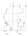
- FIG. 5 is a figure of temperature conditions and vacuum degree conditions in a 1st embodiment of the present invention. It is a figure of the process of following FIG.
- the bonding structure manufacturing technology of the present invention is a technology for manufacturing a bonding structure by bonding (particularly, solder bonding or eutectic bonding) between a plurality of members to be bonded via a heat melting member (such as solder or insert metal). About.
- the bonded structure manufacturing technology of the first embodiment of the present invention relates to a technology of manufacturing a bonded structure by solder bonding or eutectic bonding between a plurality of members to be bonded.
- This bonding structure manufacturing technique can be used also for mechanical solder bonding, but is preferably a technique for solder bonding substrates to each other or chips to each other, and an electrode structure of a pair of substrates The electrode structures of the chips, and the electrode structures of the substrate and the electrode structures of the chips are electrically connected by solder bonding.
- the substrate may be an organic substrate such as a print substrate, or a semiconductor substrate such as a silicon substrate or a compound semiconductor substrate or a dielectric substrate.
- the chip may be a semiconductor chip or a dielectric chip.
- an organic agent is applied on the semiconductor substrate, and the substrates are temporarily fixed by this organic agent. . Then, in the chamber, the organic agent is evaporated before the melting of the solder or during the melting of the solder to perform solder bonding.
- the substrate is introduced into the chamber although the cleaningless method using fluxless solder bonding is adopted in which the carboxylic acid is introduced into the chamber to reduce the oxide film of the solder.
- an organic agent that is not flux that is, a temporary tacking agent that is a non-reducing organic agent, is applied to the substrate to temporarily fix the substrates.
- the temporary tacking agent for the purpose of imparting a holding force (stacking force) between the substrates is used to prevent the displacement of the substrate by the temporary tacking agent, and prior to the reduction treatment of the oxide film with carboxylic acid or At the same time, the temporary tacking agent is evaporated and then the substrates are joined.
- the present invention can omit the cleaning process, the positional deviation between the plurality of members to be joined can be reduced.
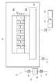
- FIG. 1 is a view showing a schematic configuration of a bonded structure manufacturing system of the present embodiment.
- the bonded structure manufacturing system 1 is a substrate soldering system for bonding substrates to each other.
- the manufacturing system 1 roughly includes a temporary fixing device 20 and a solder melting device 30.
- the temporary fixing device 20 includes a dispenser 21 and an alignment mechanism 22.
- the dispenser 21 is an application means for applying a temporary tacking agent, which is a non-reducing organic agent, to a substrate surface on which solder is formed, such as solder bumps.
- the application of the organic agent can be performed in a planar manner on one surface of the substrate surface or in discrete spots, but in the present embodiment, it is applied in a planar manner.
- the alignment mechanism 22 is a positioning means which makes the plurality of substrates face each other so as to sandwich the applied temporary tacking agent, aligns the electrode structures between the substrates, and temporarily clamps the substrates.
- Such a temporary fixing device 20 is common to a device called a flip chip bonder except that the organic agent to be applied is not a flux agent, so detailed description will be omitted.
- the solder melting apparatus 30 has a chamber 31, a supply portion 32 of carboxylic acid, and a heater 33 in the chamber 31.
- a substrate temporarily fixed by the temporary fixing device 20 is carried into the chamber 31.
- the supply unit 32 supplies carboxylic acid vapor to the chamber 31 at a predetermined timing. However, in some cases, processing may be performed in an open environment rather than in the chamber 31.
- the supply unit 32 has a carboxylic acid vapor supply system 34 and a valve 35 that opens and closes at a predetermined timing.
- the supply system 34 mixes a carrier gas such as hydrogen, a reducing gas such as carbon monoxide, or a non-oxidizing gas such as nitrogen into the carboxylic acid vapor and introduces it into the chamber 31.
- the supply system 34 has, for example, a closed vessel 36 containing a liquid of carboxylic acid, and a carrier gas supply pipe 38 for supplying a carrier gas via a valve 37.
- the carrier gas supply pipe 38 generates bubbles (bubbling) in the closed container 36.
- the supply unit 32 may be configured differently from the present embodiment.
- the heater 33 will be described.
- the heater 33 is a heating unit provided in the chamber 31.
- the heater 33 evaporates the temporary fixing agent before melting the solder or during the melting of the solder, heats the heat treatment in an atmosphere containing a carboxylic acid vapor, and solders the substrate to be a solderless joint without flux. Heat up.
- the heater 33 evaporates the temporary tacking agent prior to or simultaneously with the reduction treatment of the oxide film of the solder with a carboxylic acid.
- the solder melting apparatus 30 has an exhaust pump 39 for exhausting, and a carboxylic acid recovery unit (recovery mechanism) 40 provided on or attached to the intake or exhaust side of the exhaust pump 39 to recover the vaporized carboxylic acid.
- the carboxylic acid recovery unit 40 may be a filter attached to the intake side or the exhaust side of the exhaust pump 39, or may be a scrubber attached to the exhaust side.
- the solder melting apparatus 30 is connected via a valve 42 with a nitrogen supply pipe 41 for replacing (purging) the inside with a nitrogen atmosphere.
- the substrate temporarily fixed via the temporary bonding agent is carried into the chamber.
- the temporary tacking agent may evaporate before the solder melts, in particular, prior to, or simultaneously with, the reduction of the oxide film of the solder with carboxylic acid. Supply of carboxylic acid vapor by 32 and heating by the heater 33 are performed. Except for these points, the detailed configuration is the same as the configuration of a general solder melting apparatus, so detailed description will be omitted.
- a transfer robot or the like may be provided for delivery of the substrate between the temporary fixing device 20 and the solder melting device 30.
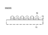
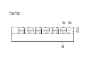
- substrates 50a and 50b (hereinafter collectively referred to collectively as the substrate 50) having solder bumps formed on the surface thereof are prepared.
- the substrate 50 is a semiconductor substrate.
- the substrate 50 has a semiconductor substrate body 51 and an electrode structure on the substrate body 51.
- a copper post 52, a barrier layer 53 on the copper post 52, and a solder bump 54 formed on the barrier layer 53 are provided on the semiconductor substrate body 51.
- the copper post 52 is a first protrusion made of copper (Cu) or a copper alloy.
- the barrier layer 53 is an under barrier metal for preventing the solder component from diffusing to the copper post 52 when the solder bump 54 is melted.
- the barrier layer 53 is a Ni / Pd / Au laminated layer laminated in the order of nickel (Ni), palladium (Pd), and gold (Au) from the substrate body 51 side.
- the copper post 52 (1st projection part) is provided as an electrode part, an electrode part is not restricted to the form which has protruded, Moreover, a material is also copper or copper alloy It is not limited to.
- the solder bumps 54 are formed of lead-free solder such as Sn—Ag (tin-silver) solder not containing lead (Pb), lead-containing solder such as Pb—Sn solder, or other solder.
- the formation itself of the solder bumps 54 is the same as the formation technique of the solder bumps 54 by the conventional plating, so detailed description will be omitted.
- insert metals for eutectic bonding can also be used.
- mass transfer occurs due to mutual diffusion of two or more kinds of substances at a processing temperature, and an alloying reaction proceeds to complete bonding.
- a type of liquid phase diffusion bonding in which insert metal etc. is temporarily melted and dissolved between bonding surfaces and then isothermally solidified and bonded using diffusion, which is a bonding method using eutectic reaction for liquefaction .
- both of the prepared pair of semiconductor substrates 50 may be configured as shown in FIG. 2, the present invention is not limited to this.
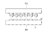
- a substrate having a first electrode portion (for example, copper post) 52, a barrier layer 53, and a solder bump 54 is used, and in the other substrate 50b, as shown in FIGS.
- the solder bumps 54 can be omitted (FIG. 3).
- the solder bumps 54 and the barrier layer 53 can be omitted on the other substrate 50b (FIG. 4).
- the substrate manufacturing burden is reduced.
- the reduction treatment can be sufficiently performed by the carboxylic acid, it is possible to solder directly to the second electrode portion even if the barrier layer and the solder bumps on one substrate 50b are omitted.
- the bonding structure manufacturing technique of the present embodiment is suitably used for the substrate 50 in which a plurality of solder bumps having a diameter of 100 ⁇ m or less are provided at a pitch interval of 150 ⁇ m or less between adjacent solder bumps.
- the substrate 50 is not limited to this case.
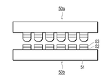
- a temporary tacking agent 55 is applied onto the substrate 50.
- the temporary tacking agent 55 is applied on the surfaces (hereinafter referred to as “bonding surfaces”) on which the plurality of substrates 50 a and 50 b face each other.
- the bonding surface corresponds to the surface on which the electrode structure such as the solder bump 54 is formed.
- the temporary tacking agent may be applied to both bonding surfaces of the plurality of substrates 50a and 50b, but may be applied only to the bonding surface of one of the substrates 50a.
- the temporary tacking agent intervenes between the pair of substrates 50a and 50b by contacting with the other substrate 50b, and holding between the substrates 50a and 50b Force (stacking force) can be applied.
- the temporary tacking agent 55 is applied in a planar manner on the substrate 50 which is a member to be joined. By uniformly applying in this manner, the holding force (stacking force) is enhanced.
- the temporary tacking agent 55 is an organic agent that is not a flux, that is, a non-reducing organic agent. That is, in the present embodiment, in spite of fluxless solder bonding, the temporary tacking agent 55 for applying a holding force (stacking force) between the substrates is applied on the bonding surface of the substrate 50 instead of the flux. .
- the non-reducing organic agent is desirable in order to prevent the possibility of causing an insulation failure called migration, even if a residue of the organic agent remains. That is, it is desirable that the temporary tacking agent 55 does not contain a component such as chlorine which adversely affects the substrate.
- the temporary tacking agent 55 can include an organic agent and a viscosity modifier (a thin liquid). This is to adjust the viscosity.
- the viscosity of the temporary tacking agent 55 is preferably in the range of 100 to 100000 (30 ° C. mPa ⁇ S), and more preferably in the range of 1600 to 66000 (30 ° C. mPa ⁇ S). This is because when the viscosity is too high, coating becomes difficult, while when the viscosity is too low, the holding force (stacking force) between the substrates is low, and the temporary tacking effect is not sufficiently obtained.
- the temporary tacking agent 55 when the substrate 50 is heated in the chamber 31, a material that evaporates before melting the solder bumps 54 (before reaching the melting point of the solder) is selected. .
- a material is selected which evaporates prior to or in parallel with the reduction treatment of the oxide film of the solder with carboxylic acid vapor.
- the boiling point of the temporary tacking agent 55 is set based on the pressure in the chamber 31 before and during the reduction treatment of the oxide film of the solder, and the substrate temperature in the reduction treatment.
- the pressure in the chamber 31 in terms of the pressure in the chamber 31, in the present embodiment, it is preferable to set the pressure in the chamber 31 to any pressure of 1 ⁇ 10 2 to 1 ⁇ 10 5 Pa before or during the reduction treatment. .
- Such a range is preferable, for example, when the pressure is lower than 1 ⁇ 10 2 Pa, the substrate may shift due to bumping of the temporary fixing agent 55, for example, and when the pressure is 1 ⁇ 10 5 Pa or higher, the pressure becomes higher than atmospheric pressure. It is because.
- the substrate temperature range in the reduction process is preferably 100 ° C. to 350 ° C.
- Such a temperature range is preferable because, for example, formic acid, which is a carboxylic acid used for reduction treatment, starts to be decomposed at about 350 ° C., it is desirable to set it to 350 ° C. or less, but depending on the type of solder, carboxylic acid vapor In some cases, the reduction treatment is performed at about 100.degree.
- the temporary tacking agent 55 has a boiling point of 100 ° C. to 350 ° C. at any pressure of 1 ⁇ 10 2 to 1 ⁇ 10 5 Pa. Is desirable.
- the type of organic agent that evaporates before or during reduction treatment may be used properly. It can.
- the melting point is 314 ° C., and about 330 ° C. to 350 ° C. is used as the solder bonding temperature.
- the melting point is 221 ° C., and about 230 ° C. to 250 ° C. is used as the solder bonding temperature.
- the temporary fixing agent 55 may be selected according to the type of material of these solders.
- the temporary tacking agent 55 have at least one non-reducing organic agent selected from isobornyl cyclohexanol, terpineol, and propylene glycol phenyl ether.
- Isobornyl cyclohexanol (MTPH) has a viscosity of 65500 (30 ° C. mPa ⁇ S) and a boiling point of 308 ° C. (5%) 313 ° C. (15%).
- Terpineol (generic name pine oil component contains ⁇ -terpineol as the main component, isomeric ⁇ -, ⁇ -terpineol and other terpine alcohols such as 97% or more) has a viscosity lower than isobornylcyclohexanol (MTPH) and has a boiling point It is 213-223 ° C. Further, propylene glycol phenyl ether has a viscosity of 22.7 (25 ° C. mPa ⁇ S) and a boiling point of 243 ° C. (760 mmHg). In particular, in the case of Sn-Ag, isobornyl cyclohexanol (MTPH) is preferred.
- MTPH isobornyl cyclohexanol
- a viscosity modifier it can select suitably from what is lower in viscosity than said isobornyl cyclohexanol, terpineol, and a propylene glycol phenyl ether.
- 2,4-diethyl-1,5-pentanediol (C 9 H 20 O 2 ) can be used as a viscosity modifier.
- the proportion of the viscosity modifier to be added to the stock solution of the organic substance can be appropriately selected, but can be 0 to 90% by weight.
- a temporary tacking agent 55 containing a plurality of non-reducing organic agents having different boiling points it is also possible to use a temporary tacking agent 55 containing a plurality of non-reducing organic agents having different boiling points.
- the temporary tacking agent component evaporates earlier than the other temporary tacking agent components, and the portion of the evaporated temporary tacking agent component is exposed earlier on the surface of the solder bump. The reduction process is started and soldered quickly.
- the temporary tacking agent does not evaporate all at one time, the temporary tacking effect can be maintained over a relatively wide temperature range, whereby the effect of preventing misalignment can be enhanced.
- some temporary tacking agent components evaporate before melting the solder, and other temporary tacking agent components evaporate while melting the solder, and a mixture of these components is tentatively It can be used as a stopper 55.
- the alignment mechanisms 22 make the plurality of substrates 50a and 50b face each other so as to sandwich the temporary tacking agent 55, align the substrates 50a and 50b with each other, and then, the substrates 50a and 50b. Match each other.
- a holding force (stacking force) is applied between the substrates 50a and 50b by the temporary bonding agent 55, and the substrates 50a and 50b are temporarily fixed to each other.
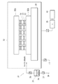
- the substrates 50 a and 50 b in the temporarily fixed state are carried into the chamber 31.
- the substrates 50a and 50b are disposed on the heater 33, for example, via a tray (not shown).
- FIG. 6 shows a pair of substrates 50a and 50b, a plurality of pairs of substrates, a plurality of pairs of chips, a plurality of pairs of substrates and chips, etc. may be carried in as members to be joined at one time. .
- the process is performed under the temperature conditions and the degree of vacuum as shown in FIG.
- the inside of the chamber 31 is evacuated to, for example, about 10 to 50 Pa by the pump 39.
- the degree of evacuation is not limited to about 10 to 50 Pa, and can be appropriately adjusted.
- the substrates 50a and 50b are heated by the heater 33 to raise the substrate temperature.
- carboxylic acid vapor is introduced into the chamber 31.
- the inside of the chamber 31 becomes about 100 to 10000 Pa.
- carboxylic acid vapor at least before the temperature of the substrates 50a, 50b reaches the melting point of the solder.
- the solder is Sn-3.5Ag (melting point 221 ° C.)
- it is heated to about 230 ° C. to 250 ° C. suitable for soldering, but the reduction effect by carboxylic acid is strengthened above about 200 ° C. Processing is started.
- Pb-5Sn melting point 314 ° C.
- heating to about 330 ° C. to 350 ° C. suitable for soldering is performed, but at 250 ° C. or more, the reduction effect by carboxylic acid is intensified, and the reduction treatment is started.
- the temporary tacking agent 55 is evaporated prior to or in parallel with the reduction treatment of the oxide film of the solder with the carboxylic acid vapor. That is, when the solder is Sn-3.5Ag, reduction treatment is performed at about 200 ° C., for example, at about 180 ° C. to 250 ° C., and solder bonding is performed at about 230 ° C. to 250 ° C. Or, the temporary holding agent 55 evaporates in parallel with the reduction treatment. Similarly, when the solder is Pb-5Sn, reduction processing is performed at around 250 ° C., for example, at around 220 ° C. to 350 ° C., and solder bonding is performed at about 330 ° C. to 350 ° C.
- the temporary holding agent 55 evaporates in parallel with the reduction treatment. Even in the case of using a solder of another material, the temporary tacking agent 55 is evaporated prior to or in parallel with the reduction treatment of the oxide film of the solder with a carboxylic acid vapor. As shown in FIG. 7, evacuation to about 10 to 50 Pa facilitates evaporation of the temporary fixing agent 55. That is, it is useful to temporarily increase the degree of vacuum in the chamber 31 so that the temporary tacking agent 55 is easily evaporated.
- the temporary tacking agent 55 gradually evaporates, the solder bumps 54 are gradually exposed to carboxylic acid vapor. As a result, the oxide film on the surface of the solder bump 54 is reduced.
- the temporary tacking agent 55 one containing plural kinds of non-reducing organic agents having different boiling points can be used.
- at least some of the tackifier components evaporate faster than the other tackifier components.
- the reduction treatment was started earlier, but all the temporary tackifier components did not evaporate at one time due to the difference in boiling point, so a relatively wide temperature range Can maintain the temporary holding effect.
- the temporary bonding agent 55 may be partially or entirely evaporated before the solder bump 54 is melted, and may be evaporated during the melting of the solder bump 54. From the viewpoint of preventing misalignment, it is desirable to evaporate the temporary tacking agent 55 only during melting of the solder bumps 54, but it is sufficient to expose the surface of the solder bumps 54 to contact with carboxylic acid vapor at an early stage. From the viewpoint of reduction treatment, it is desirable to evaporate part or all of the temporary tacking agent before melting the solder bumps 54. Specifically, at least a portion of the temporary tacking agent 55 is evaporated to expose the solder bumps 54, and the oxide film is reduced and removed at the exposed portions.
- solder bonding Even if the temporary bonding agent 55 evaporates completely before the solder bumps 54 are melted, the solder bonding can be performed without positional deviation. Then, when the temperature of the substrates 50a and 50b is a solder bonding temperature (for example, about 230 ° C. to 250 ° C. when the solder is Sn-3.5Ag), the solder is melted at that portion and soldering (solder bonding) Will be The soldering agent (reflow) is completed when the temporary bonding agent 55 is completely evaporated, the solder bump 54 is completely exposed, the reduction treatment is performed, and the solder is completely melted by sufficiently melting the solder. .
- a solder bonding temperature for example, about 230 ° C. to 250 ° C. when the solder is Sn-3.5Ag
- the temporary tacking agent 55 If a large displacement can be prevented by the temporary tacking agent 55, the surface tension of the solder acts on itself to be self-aligned (self-aligned) to correct the displacement.
- the temporary tacking agent 55 is evaporated during the melting of the solder 54, the temporary holding effect can be maintained until the soldering effect by the melting of the solder 54 is produced. Further, even when the temporary tacking agent 55 is evaporated before the melting of the solder 54, the time taken from the temporary tacking effect to completely disappear and the temporary tacking effect disappears to the completion of the soldering process becomes short. Therefore, positional deviation of the substrates 50a and 50b is prevented or reduced.
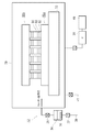
- the temperature drop of the substrate temperature is started, and the exhaust pump 39 exhausts the carboxylic acid vapor.
- the carboxylic acid recovery unit (recovery mechanism) 40 recovers the vaporized carboxylic acid. Thereafter, the inside of the chamber 31 is purged (purged) by a gas such as nitrogen introduced from the nitrogen supply pipe 41, and then the bonded structure in which the solder bonding is completed, that is, the solder bonded substrate 50 is taken out.
- underfill resin 56 is filled between the plurality of substrates 50a and 50b with respect to the solder bonded substrate 50 taken out. This is to increase the bonding strength of the solder bonded substrate 50 and to protect the same.
- the organic agent (temporary fixing agent) between the substrates 50a and 50b is already evaporated and removed. Therefore, unlike the case of ordinary solder bonding using flux, substantially no organic agent is present between the substrates 50a and 50b, and no residue is left even after cleaning.
- the step of filling the underfill resin between the substrates it is possible to prevent the void from being generated due to the residue not being able to be sufficiently filled with the underfill resin.
- the temporary tacking agent is not a rosin-based reducing organic agent but a non-reducing organic agent. Since it is an agent, the occurrence of insulation defects called migration is also prevented.
- fluxless solder bonding is performed with a positional deviation of 2 ⁇ m or less even in the bonding of a substrate on which solder bumps having a diameter and pitch of about several tens of ⁇ m are formed by the technique of this embodiment. Can.
- the present invention is not limited to this case, and can be changed suitably.
- the temperature conditions and the vacuum degree conditions are not limited to those shown in FIG.
- the reduction treatment may be performed by holding the substrate temperature at a temperature about 50 to 80 ° C. lower than the solder bonding temperature for a certain period of time.
- the temperature of the substrate may be controlled by carrying the substrates 50 a and 50 b on and off the heater 33 while keeping the temperature of the heater 33 constant.
- the organic agent 55 evaporates before the solder 54 melts or during the melting of the solder 54. Therefore, no cleaning for removing the organic agent 55 is necessary after the solder bonding. Accordingly, no residue of the organic agent 55 remains, so that migration or other contamination does not occur particularly when the electrode structure of the substrate 50a and the electrode structure of the substrate 50b are soldered to each other. Further, in the step of filling the underfill resin in the gap, it is possible to prevent the void from being generated due to the underfill resin not being sufficiently filled by the residue of the organic substance.
- solder bonding is performed fluxless using the temporary fixing agent 55 which is a non-reducing organic agent as the organic agent. Therefore, the holding force (stacking force) can be applied to the substrate by the temporary bonding agent 55 while the fluxless solder bonding is performed, and the positional deviation can be prevented. Also, even if a trace amount of temporary tacking agent remains, unlike the case of the fluxing agent, migration or other contamination does not occur.
- the temporary tacking agent 55 since the temporary tacking agent is evaporated prior to or in parallel with the reduction treatment of the oxide film of the solder 54 with the carboxylic acid vapor, the solder bumps are gradually evaporated as the temporary tacking agent 55 gradually evaporates. 54 is gradually exposed to carboxylic acid vapor. Therefore, the temporary tacking agent 55 does not inhibit the reduction process by the carboxylic acid vapor while preventing the positional deviation of the substrates 50a and 50b. Even if the temporary bonding agent 55 evaporates completely before the solder bumps 54 are melted, the solder bonding can be performed without positional deviation. That is, the positional deviation at the time of loading of the substrate is prevented, and the surface tension of the solder due to the melting of the solder bumps 54 causes self alignment (self alignment) to correct the positional deviation.
- the temporary tacking agent 55 has a boiling point of 100 ° C. to 350 ° C. at any pressure of 1 ⁇ 10 2 to 1 ⁇ 10 5 Pa. While the agent 55 remains to provide retention, it does not inhibit the reduction process.
- the temporary fixing agent 55 is at least one non-reducing organic agent selected from isobornyl cyclohexanol, terpineol, and propylene glycol phenyl ether. While the temporary tacking agent remains to provide holding power, it does not inhibit the reduction treatment. Also, it does not contain substances that cause migration or other contamination. Furthermore, the viscosity is appropriate and can provide sufficient holding force (stacking force).
- the temporary tacking agent 55 contains plural kinds of non-reducing organic agents having different boiling points, at least a portion of the temporary tacking agent component evaporates earlier than the other temporary tacking agent components. In the part where the evaporated temporary tackifier component was present, the reduction treatment can be started early. On the other hand, since the temporary tacking agent does not evaporate all at one time, the temporary tacking effect can be maintained over a relatively wide temperature range, whereby the effect of preventing misalignment can be enhanced.
- the temporary tacking agent 55 is diluted by the viscosity modifier so as to have a viscosity of 1 ⁇ 10 2 to 1 ⁇ 10 5 mPa ⁇ s, so that the viscosity is too high to prevent application. It can be prevented that the viscosity is too low and the holding power of the substrate is too small.
- solder bumps 54 with a diameter of 100 ⁇ m or less are useful in bonding of substrates in which the pitch between adjacent bumps is 150 ⁇ m or less.
- the oxide film can be sufficiently reduced by carboxylic acid vapor, so one of the pair of substrates 50a and 50b is The barrier layer 53 and the solder bumps 54 can be omitted, and only the copper posts (second protrusions made of copper) 52 can be formed and soldered directly. Thereby, the burden of manufacturing the substrate 50b can be reduced.
- the temporary tacking agent 55 is coated in a planar shape on the substrate 50, the amount of the temporary tacking agent 55 is increased, and the holding force (stacking force) is increased.
- the temporary tacking agent is applied in a planar manner on the substrate.
- the temporary tacking agent is applied in the form of spots at a plurality of locations.
- the joint structure manufacturing technique of the present embodiment is the same as that of the first embodiment, and therefore, the same members as those of the first embodiment are the same as those of the first embodiment. While showing using a number, detailed explanation is omitted.
- the dispenser 21 discretely spots temporary fixing agents, which are non-reducing organic agents, on the substrate surface on which solder such as solder bumps is formed.
- FIG. 11 shows an example where the temporary tacking agent 55 is discretely applied in the form of spots.
- 11 (a) is a top view of the substrate 50a, and
- FIG. 11 (b) shows a state in which the substrates 50a and 50b are temporarily fixed.
- temporary fixing agents 55 are applied in the form of spots at the four corners of a rectangular substrate (chip).
- the flux has to be applied so as to be in contact with the solder surface because the main purpose is to reduce and remove the oxide film on the solder surface by the flux.
- the temporary fixing agent 55 since the reduction of the oxide film on the surface of the solder 54 is performed by the carboxylic acid vapor, it is sufficient if the temporary fixing agent 55 merely provides a holding force (stacking force) between the substrates. Therefore, it is not necessary to apply the temporary tacking agent 55 in contact with the surface of the solder 54. Therefore, as shown in FIG. 11, the temporary tacking agent 55 may be applied so as not to contact the surface of the solder 54.
- the type of temporary tacking agent 55, temperature conditions, vacuum degree conditions, carboxylic acid gas, solder bump diameter, pitch size and the like are the same as in the first embodiment.
- the self-alignment is performed to correct the misalignment.
- the effect of self alignment is high.
- the temporary tacking agent 55 is applied in a spot shape (point shape) has been described, but the present embodiment is not limited to this case, and the temporary tacking agent 55 is formed in a line shape (linear shape). It can also be applied. Also, the temporary tacking agent 55 can be applied in the form of one spot or one line instead of discretely applying to a plurality of places.
- the temporary tacking agent in the case where the temporary tacking agent is applied so as not to contact the solder surface, the temporary tacking agent does not enter the gap between the solder bumps, and it is easy to evaporate and remove it.
- the temporary tacking agent 55 is an organic agent that is not a flux, that is, a temporary tacking agent that is a non-reducing organic agent is applied to the substrate to temporarily tack between the substrates Explained.
- the temporary tacking agent 55 is not a flux agent but a non-reductive organic agent as a temporary tacking agent 55 in the sense that migration or other contamination does not occur even if a trace amount of the temporary tacking agent 55 remains without being completely evaporated. Is desirable, but the invention is not limited in this case.
- the organic agent is evaporated before the solder is melted, so that the flux agent is temporarily used as the organic agent.
- the step of removing the flux by cleaning processing such as solution cleaning and ion etching after solder bonding is not necessary. Therefore, for example, even when the diameter of the solder bump 54 and the pitch interval between adjacent solder bumps are several tens of ⁇ m or less, it is not necessary to be aware of the problem that the flux is difficult to remove. Therefore, according to the present invention, even if a flux agent is used, since no flux residue is generated after solder bonding, it is possible to prevent the occurrence of insulation failure called migration. In addition, in the step of finally filling the underfill resin 56 between the substrates, it is possible to prevent the occurrence of a void called a void because the underfill resin 56 can not be sufficiently filled by the flux residue.
- the organic agent is applied so as to be sandwiched between the plurality of substrates 50a and 50b, and the plurality of substrates are temporarily fixed and temporarily fixed via the organic agent. Heating a plurality of members to be joined, evaporating the organic agent before melting of the solder or during melting of the solder, melting the solder in the chamber 31 and solder-bonding the plurality of substrates via the solder As long as it is, it is widely applicable.
- the present invention can also be applied to the technology of solder molding. That is, the present embodiment relates to a heating and melting method for forming solder bumps on the substrate 50a which is a member to which the solder material 54b is attached.
- the temporary bonding agent 55 which is an organic agent is applied to the surface of the substrate 50a, and the position of the solder material 54b is set via the temporary bonding agent (organic agent) 55. Temporarily fix. Then, the temporary tacking agent 55 is evaporated before melting of the solder material 54 b or during melting of the solder material 54 b. Then, the solder material 54b is melted to form the solder bumps 54. Also in this case, displacement of the solder material 54b is prevented.
- a heated melt processing system is provided for such processing.
- This system is similar to the system of FIG. It is a heating and melting processing system which heats the member to which the solder material 54b adheres, heat-melts the solder material 54b, and shapes a solder. Then, the solder material 54b is attached to the member, and the temporary fixing device 20 for applying the organic agent to the surface of the member to temporarily fix the solder material 54b, and the solder material is temporarily fixed via the temporary fixing agent.
- heating means solder melting device 30 which heats a member, and supply means which supplies carboxylic acid vapor to the member, and the heating means melts the solder material before melting the solder material or While evaporating the temporary tacking agent, the member is heated to form solder in a fluxless manner in an atmosphere containing the carboxylic acid vapor.
- Example> First Embodiment Copper posts 52 made of copper, barrier layers (Ni / Pd / Au) 53 on the copper posts 52, and Sn—Ag solder bumps 54 formed on the barrier layer 53 on a silicon substrate (5 mm square, 25 mm square)
- the substrates 50a and 50b having the above were formed. A pair of the substrates 50a and 50b was prepared.
- the diameter of the solder bumps 54 was 100 microns, and the pitch (distance between centers) between adjacent solder bumps was 250 microns.
- a temporary tacking agent was prepared by diluting isobornyl cyclohexanol with a viscosity modifier (2,4-diethyl-1,5-pentanediol). At this time, the ratio of the viscosity modifier was 0 wt%, 30 wt%, 50 wt%, 70 wt%, 90 wt%, respectively.
- the temporary fixing agent 55 was apply
- the substrates 50a and 50b were soldered well without positional deviation.
- the diameter of the solder bump 54 was 20 microns, and the pitch (distance between centers) between adjacent solder bumps was 40 microns.
- the other conditions are the same as in the first embodiment. Also in this case, the positional deviation of the substrates 50a and 50b is 2 ⁇ m or less, and the substrates are soldered well.
- terpineol was temporarily fixed using a temporary adhesive prepared by diluting with a viscosity modifier (2,4-diethyl-1,5-pentanediol).
- the ratio of the viscosity modifier was 0 wt%, 30 wt%, 50 wt%, 70 wt%, and 90 wt%, respectively.
- the positional deviation is small, and solder bonding is satisfactorily performed.
- the yield slightly decreased compared to the case of the first example.
- terpineol was temporarily fixed using a temporary tacking agent prepared by diluting with a viscosity modifier (2,4-diethyl-1,5-pentanediol). Also in this case, as in the second embodiment, the positional deviation is small, and the solder bonding is good. However, the yield was worse than in the second example.
- propylene glycol phenyl ether was temporarily fixed using a temporary adhesive prepared by diluting it with a viscosity modifier (2,4-diethyl-1,5-pentanediol).
- the ratio of the viscosity modifier was 0 wt%, 30 wt%, 50 wt%, 70 wt%, and 90 wt%, respectively.
- the misalignment was small, and the solder was well bonded.
- the yield was worse than in the first and third examples.
- the same temporary tacking agent was discretely applied in the form of spots on the same substrate as in the first embodiment described above at four points (four points). At this time, it was possible to reduce the positional deviation by the temporary fixing action by the temporary fixing agent, and to perform the solder bonding.
- the solder bumps 54 were melted to cause self-alignment (self-alignment) by the action of the surface tension of the solder, and the misalignment was eliminated. Therefore, in practice, even when the temporary bonding agent is applied discretely, the plurality of substrates can be soldered together to manufacture a soldered substrate, although the cleaning process can be omitted. It was found that the positional deviation between them could be reduced.
- the ninth embodiment On the same substrate as in the first embodiment, the temporary adhesive prepared by diluting terpineol to 0% to 90% by weight with a viscosity modifier (2,4-diethyl-1,5-pentanediol) was spotted at 4 points Applied discretely. Further, also on the same substrate as in the second embodiment, the temporary tacking agent was applied discretely in the form of spots at four locations. Also in these cases, it is possible to reduce the positional deviation between the plurality of substrates, and it was at a practical level.
- a viscosity modifier 2,4-diethyl-1,5-pentanediol
Landscapes
- Engineering & Computer Science (AREA)
- Mechanical Engineering (AREA)
- Manufacturing & Machinery (AREA)
- Microelectronics & Electronic Packaging (AREA)
- Electric Connection Of Electric Components To Printed Circuits (AREA)
- Wire Bonding (AREA)
Abstract
Description
本発明の第1実施形態の接合構造体製造技術は、複数の被接合部材間を半田接合または共晶接合して接合構造体を製造する技術に関する。この接合構造体製造技術は、機械的な半田接合にも用いることができるが、好ましくは、基板同士、チップ同士、あるいは、基板とチップとを半田接合する技術であり、一対の基板の電極構造同士、チップの電極構造同士、および基板の電極構造とチップの電極構造とを半田接合により電気的に接続するものである。
次に、本発明の第2実施形態について説明する。上記の第1実施形態では、仮止め剤を基板上に面状に塗布する場合を説明した。しかしながら、第2実施形態では、複数の箇所においてスポット状に仮止め剤が塗布される。この点を除いて、本実施形態の接合構造体製造技術は、第1実施形態の場合と同様であるので、第1実施形態にける部材と同様の部材には、本実施形態においても同じ部材番号を用いて示すとともに、詳しい説明を省略する。
上記の第1、第2実施形態においては、仮止め剤55として、フラックスではない有機剤、つまり、非還元性の有機剤である仮止め剤を基板に塗布して基板間を仮止めする場合を説明した。
次に本発明の第4実施形態について説明する。
<第1実施例>
シリコン基板(5mm角、25mm角)に、銅製のカッパーポスト52と、カッパーポスト52上のバリア層(Ni/Pd/Au)53と、バリア層53上に形成されたSn-Ag半田バンプ54とが形成された基板50a、50bを用意した。上記の基板50a、50bは、一対用意した。なお、半田バンプ54の直径が100ミクロンであり、隣接する半田バンプ間のピッチ(中心間の距離)が250ミクロンのものを用いた。
半田バンプ54の直径が20ミクロンであり、隣接する半田バンプ間のピッチ(中心間の距離)が40ミクロンのものを用いた。その他の条件は、上記第1実施例と同様とした。この場合も、基板50a、50bの位置ずれは、2μm以下となっており、良好に半田接合された。
上記の第1実施例と同じ基板において、ターピネオールを粘度調整剤(2,4-ジエチル-1,5-ペンタンジオール)で薄めて製造した仮止め剤を用いて仮止めした。粘度調整剤の割合は0重量%、30重量%、50重量%、70重量%、90重量%とした場合で、それぞれ実施した。この場合も、第1実施例と同様に、位置ずれが少なく、良好に半田接合された。ただし、収率は、第1実施例の場合と比べて若干低下した。
上記の第2実施例と同じ基板において、ターピネオールを粘度調整剤(2,4-ジエチル-1,5-ペンタンジオール)で薄めて製造した仮止め剤を用いて仮止めした。この場合も、第2実施例と同様に、位置ずれが少なく、良好に半田接合された。ただし、収率は、第2実施例の場合と比べて悪かった。
上記の第1実施例と同じ基板において、プロピレングリコールフェニル・エーテルを粘度調整剤(2,4-ジエチル-1,5-ペンタンジオール)で薄めて製造した仮止め剤を用いて仮止めした。粘度調整剤の割合は0重量%、30重量%、50重量%、70重量%、90重量%とした場合で、それぞれ実施した。この場合も、位置ずれが少なく、良好に半田接合された。ただし、収率は、第1実施例および第3実施例の場合と比べて悪かった。
上記の第2実施例と同じ基板において、プロピレングリコールフェニル・エーテルを粘度調整剤(2,4-ジエチル-1,5-ペンタンジオール)で薄めて製造した仮止め剤を用いて仮止めした。この場合も、第2実施例と同様に、位置ずれが少なく、良好に半田接合された。ただし、収率は、第2実施例および第4実施例の場合と比べて悪かった。
上記の第1実施例と同じ基板において、同じ仮止め剤を4箇所(4点)において、スポット状に離散的に塗布した。このとき、仮止め剤による仮止め作用により位置ずれを軽減して、半田接合することができた。なお、本実施例においては、半田接合前の時点で、基板50a、50b間に20μm程度の小さな位置ずれを生じさせたサンプルでも実験してみたが、仮止め作用により大きな位置ずれを防止することができれば、半田バンプ54が溶融することによる半田の表面張力の作用によって、セルフアライメント(自己整合)されて、位置ずれが解消した。したがって、実用的には、仮止め剤を離散的に塗布するによっても、複数の基板同士を半田接合して半田付け基板を製造する際に、クリーニング処理を省略できるにもかかわらず、複数の基板間の位置ずれを軽減できることがわかった。
上記の第2実施例と同じ基板において、同じ仮止め剤を4箇所において、スポット状に離散的に塗布した。この場合も、複数の基板間の位置ずれを軽減できた。
第1実施例と同じ基板において、ターピネオールを粘度調整剤(2,4-ジエチル-1,5-ペンタンジオール)で0%~90重量%に薄めて製造した仮止め剤を、4箇所でスポット状に離散的に塗布した。また、第2実施例と同じ基板においても、同様に、仮止め剤を、4箇所でスポット状に離散的に塗布した。これらにおいても、複数の基板間の位置ずれを軽減でき、実用できる水準であった。
第1実施例と同じ基板において、プロピレングリコールフェニル・エーテルを粘度調整剤(2,4-ジエチル-1,5-ペンタンジオール)で0~90重量%に薄めて製造した仮止め剤を、4箇所でスポット状に離散的に塗布した。また、第2実施例と同じ基板においても、同様に、仮止め剤を、4箇所でスポット状に離散的に塗布した。これらにおいても、複数の基板間の位置ずれを軽減でき、実用できる水準であった。
20 仮止め装置、
21 ディスペンサ、
22 アライメント機構、
30 半田溶融装置、
31 チャンバ、
32 カルボン酸の供給部、
33 ヒータ、
34 供給系、
35 バルブ、
36 密閉容器、
37 バルブ、
38 キャリアガス供給管、
39 排気ポンプ、
40 カルボン酸回収部、
41 窒素供給管、
42 バルブ、
50(50a、50b) 半導体基板、
51 半導体基板本体、
52 カッパーポスト(第1突起部)、
53 バリア層、
54 半田バンプ、
55 仮止め剤、
56 アンダーフィル樹脂。
Claims (25)
- 加熱溶融材を介して複数の被接合部材間を接合して接合構造体を製造する接合構造体製造方法において、
前記複数の被接合部材の少なくとも一方に加熱溶融材が形成された被接合部材を準備する段階と、
前記複数の被接合部材が互いに対向する面上に有機剤を塗布して、当該有機剤を介して複数の被接合部材間を仮止めする仮止め段階と、
前記加熱溶融材を溶融して当該加熱溶融材を介して複数の被接合部材間を接合する接合段階と、
前記接合段階の前または後に、前記有機剤を加熱により蒸発させる蒸発段階と、を有することを特徴とする接合構造体製造方法。 - 加熱溶融材を介して複数の被接合部材間を接合して接合構造体を製造する接合構造体製造方法において、
前記複数の被接合部材の少なくとも一方に加熱溶融材が形成された被接合部材を準備する段階と、
前記複数の被接合部材が互いに対向する面上に有機剤を塗布して、当該有機剤を介して複数の被接合部材間を仮止めする仮止め段階と、
仮止めされた複数の被接合部材を加熱して、前記加熱溶融材の溶融する前または前記加熱溶融材の溶融中に前記有機剤を蒸発させる蒸発段階と、
前記加熱溶融材を溶融して当該加熱溶融材を介して複数の被接合部材間を接合する接合段階と、を有することを特徴とする請求項1に記載の接合構造体製造方法。 - 前記加熱溶融材は、半田材または共晶接合材であり、前記接合段階は、複数の被接合部材間を半田接合または共晶接合することを特徴とする請求項2に記載の接合構造体製造方法。
- 前記接合段階は、前記複数の被接合部材のうちの一方の被接合部材に設けられた電極構造と、他方の被接合部材に設けられた電極構造とを電気的に接続することを特徴とする2または3に記載の接合構造体製造方法。
- 前記加熱溶融材を全て蒸発させた後に、前記接合段階において前記加熱溶融材を溶融することを特徴とする請求項2~4のいずれか1項に記載の接合構造体製造方法。
- 前記仮止め段階は、前記有機剤として非還元性の有機剤である仮止め剤を塗布するものであり、
前記接合段階は、カルボン酸蒸気を含む雰囲気中で加熱処理し、フラックスレスで半田接合または共晶接合するものである、ことを特徴とする請求項5に記載の接合構造体製造方法。 - チャンバ中に前記カルボン酸蒸気を供給する供給段階を有し、
前記接合段階は、前記チャンバ内で行われることを特徴とする請求項6に記載の接合構造体製造方法。 - 前記接合段階に先立って前記カルボン酸蒸気を供給し、
前記蒸発段階は、前記カルボン酸蒸気による前記加熱溶融材の酸化膜の還元処理に先立ってまたは当該還元処理と並行して前記仮止め剤を蒸発させる、ことを特徴とする請求項5または6に記載の接合構造体製造方法。 - 前記蒸発段階は、前記加熱溶融材の溶融する前に前記有機剤を蒸発させることを特徴とする請求項6~8のいずれか1項に記載の接合構造体製造方法。
- 前記接合段階の後に、前記有機剤を洗浄除去する作業をすることなく前記複数の被接合部材間にアンダーフィル樹脂を充填することを特徴とする請求項5~9のいずれか1項に記載の接合構造体製造方法。
- 前記蒸発段階では、前記仮止め剤が蒸発しやすいように、前記チャンバ内の真空度を一時的に高めることを特徴とする請求項6~10のいずれか1項に記載の接合構造体製造方法。
- 前記仮止め剤は、圧力1×10²乃至1×10⁵Paのいずれかの圧力において、100℃乃至350℃の沸点を有することを特徴とする請求項6~11のいずれか1項に記載の接合構造体製造方法。
- 前記仮止め剤は、イソボルニルシクロヘキサノール、ターピネオール、およびプロピレングリコールフェニル・エーテルから選ばれた少なくとも1つの非還元性の有機剤であることを特徴とする請求項6~12のいずれか1項に記載の接合構造体製造方法。
- 前記仮止め剤は、互いに沸点の異なる複数種類の非還元性の有機剤を含むことを特徴とする請求項6~13のいずれか1項に記載の接合構造体製造方法。
- 前記仮止め剤は、粘度1×10²乃至1×10⁵mPa・sになるように粘度調整剤により希釈されていることを特徴とする請求項6~14のいずれか1項に記載の接合構造体製造方法。
- 前記複数の被接合部材の少なくとも一方に形成された半田は、直径が100μm以下の半田バンプであり、隣接する半田バンプ間のピッチ間隔が150μm以下であることを特徴とする請求項6~15のいずれか1項に記載の接合構造体製造方法。
- 前記仮止め段階は、前記被接合部材上にスポット状またはライン状に前記仮止め剤が塗布されることを特徴とする請求項6~16のいずれか1項に記載の接合構造体製造方法。
- 前記仮止め段階は、前記被接合部材上に、複数の箇所に離散して前記仮止め剤が塗布されることを特徴とする請求項17に記載の接合構造体製造方法。
- 前記仮止め剤は、前記半田の表面から離隔されて前記被接合部材上に塗布されることを特徴とする請求項17または18に記載の接合構造体製造方法。
- 前記仮止め段階は、前記被接合部材上に、面状に前記仮止め剤が塗布されることを特徴とする請求項6~16のいずれか1項に記載の接合構造体製造方法。
- 前記複数の被接合部材の一方に設けられた電極構造は、第1電極層と、前記第1電極部上に形成されたバリア層と、前記バリア層上に形成された半田バンプとからなり、
前記複数の被接合部材の他方に設けられた電極構造は、第2電極層とからなり、
半田接合によって、前記半田バンプと前記第2電極層とが接合されることを特徴とする請求項6~20のいずれか1項に記載の接合構造体製造方法。 - 加熱溶融材を介して複数の被接合部材間を接合して接合構造体を製造する接合構造体製造システムにおいて、
前記複数の被接合部材の少なくとも一方に加熱溶融材が形成された被接合部材に非還元性の有機剤である仮止め剤を塗布する塗布手段と、
前記仮止め剤を介して積層された状態で仮止めされた前記複数の被接合部材を加熱する加熱手段と、
前記複数の被接合部材に対してカルボン酸蒸気を供給する供給手段と、を有し、
前記加熱手段は、前記加熱溶融材の溶融する前または前記加熱溶融材の溶融中に前記仮止め剤を蒸発させる一方、前記カルボン酸蒸気を含む雰囲気中においてフラックスレスで接合するために前記被接合部材を加熱することを特徴とする接合構造体製造システム。 - 半田材が付着した部材を加熱して半田材を加熱溶融処理して半田を成形する加熱溶融処理方法であって、
前記部材上に半田材を付着させるとともに、部材の表面に有機剤を塗布して、当該有機剤を介して前記半田材の位置を仮止めする仮止め段階と、
前記加熱溶融材の溶融する前または前記加熱溶融材の溶融中に前記有機剤を蒸発させる蒸発段階と、
前記加熱溶融材を溶融して半田を成形する成形段階と、を有することを特徴とする請求項1に記載の加熱溶融処理方法。 - 半田材が付着した部材を加熱して半田材を加熱溶融処理して半田を成形する加熱溶融処理方法であって、
前記部材上に半田材を付着させるとともに、部材の表面に有機剤を塗布して、当該有機剤を介して前記半田材を仮止めする仮止め段階と、
前記半田材の溶融する前または前記半田材の溶融中に前記有機剤を蒸発させる蒸発段階と、
前記半田材を溶融して半田を成形する成形段階と、を有することを特徴とする加熱溶融処理方法。 - 半田材が付着した部材を加熱して半田材を加熱溶融処理して半田を成形する加熱溶融処理システムにおいて
前記部材上に半田材を付着させるとともに、半田材を仮止めするために部材の表面に有機剤を塗布する塗布手段と、
前記仮止め剤を介して半田材が仮止めされた部材を加熱する加熱手段と、
前記部材に対してカルボン酸蒸気を供給する供給手段と、を有し、
前記加熱手段は、前記半田材の溶融する前または前記半田材の溶融中に前記仮止め剤を蒸発させる一方、前記カルボン酸蒸気を含む雰囲気中においてフラックスレスで半田を成形するために前記部材を加熱することを特徴とする加熱溶融処理システム。
Priority Applications (6)
| Application Number | Priority Date | Filing Date | Title |
|---|---|---|---|
| US13/806,907 US8757474B2 (en) | 2010-06-28 | 2011-06-24 | Bonding structure manufacturing method, heating and melting treatment method, and system therefor |
| KR1020127033994A KR101805147B1 (ko) | 2010-06-28 | 2011-06-24 | 접합 구조체 제조 방법 및 가열 용융 처리 방법과 그 시스템 |
| CN201180031174.9A CN102960077B (zh) | 2010-06-28 | 2011-06-24 | 接合构造体制造方法及加热熔融处理方法以及它们的系统 |
| EP11800738.4A EP2587900B1 (en) | 2010-06-28 | 2011-06-24 | Joint structure manufacturing method, heating and melting treatment method, and system for same |
| US14/275,153 US9119336B2 (en) | 2010-06-28 | 2014-05-12 | Bonding structure manufacturing method, heating and melting treatment method, and system therefor |
| US14/799,796 US20150314385A1 (en) | 2010-06-28 | 2015-07-15 | Bonding structure manufacturing method, heating and melting treatment method, and system therefor |
Applications Claiming Priority (4)
| Application Number | Priority Date | Filing Date | Title |
|---|---|---|---|
| JP2010-146337 | 2010-06-28 | ||
| JP2010146337 | 2010-06-28 | ||
| JP2010-166448 | 2010-07-23 | ||
| JP2010166448A JP5807221B2 (ja) | 2010-06-28 | 2010-07-23 | 接合構造体製造方法および加熱溶融処理方法ならびにこれらのシステム |
Related Child Applications (2)
| Application Number | Title | Priority Date | Filing Date |
|---|---|---|---|
| US13/806,907 A-371-Of-International US8757474B2 (en) | 2010-06-28 | 2011-06-24 | Bonding structure manufacturing method, heating and melting treatment method, and system therefor |
| US14/275,153 Division US9119336B2 (en) | 2010-06-28 | 2014-05-12 | Bonding structure manufacturing method, heating and melting treatment method, and system therefor |
Publications (1)
| Publication Number | Publication Date |
|---|---|
| WO2012002273A1 true WO2012002273A1 (ja) | 2012-01-05 |
Family
ID=45401990
Family Applications (1)
| Application Number | Title | Priority Date | Filing Date |
|---|---|---|---|
| PCT/JP2011/064532 Ceased WO2012002273A1 (ja) | 2010-06-28 | 2011-06-24 | 接合構造体製造方法および加熱溶融処理方法ならびにこれらのシステム |
Country Status (7)
| Country | Link |
|---|---|
| US (3) | US8757474B2 (ja) |
| EP (1) | EP2587900B1 (ja) |
| JP (1) | JP5807221B2 (ja) |
| KR (1) | KR101805147B1 (ja) |
| CN (1) | CN102960077B (ja) |
| TW (1) | TWI548317B (ja) |
| WO (1) | WO2012002273A1 (ja) |
Cited By (4)
| Publication number | Priority date | Publication date | Assignee | Title |
|---|---|---|---|---|
| WO2014156835A1 (ja) * | 2013-03-29 | 2014-10-02 | 三菱マテリアル株式会社 | 金属-セラミックス板積層体の製造装置及び製造方法、パワーモジュール用基板の製造装置及び製造方法 |
| US20180326545A1 (en) * | 2015-09-30 | 2018-11-15 | Origin Electric Company, Limited | Method for producing soldered product |
| US20220173069A1 (en) * | 2019-02-20 | 2022-06-02 | Commissariat A L'energie Atomique Et Aux Energies Alternatives | Method for assembling components implementing a pre-treatment of the solder bumps allowing an assembly by fluxless and residue-free soldering |
| US20220293436A1 (en) * | 2021-03-11 | 2022-09-15 | Taiwan Semiconductor Manufacturing Company Limited | Semiconductor substrate bonding tool and methods of operation |
Families Citing this family (44)
| Publication number | Priority date | Publication date | Assignee | Title |
|---|---|---|---|---|
| JP5807221B2 (ja) | 2010-06-28 | 2015-11-10 | アユミ工業株式会社 | 接合構造体製造方法および加熱溶融処理方法ならびにこれらのシステム |
| KR20130084893A (ko) * | 2012-01-18 | 2013-07-26 | 삼성전자주식회사 | 멀티-칩 패키지 및 그의 제조 방법 |
| KR101330225B1 (ko) * | 2012-05-25 | 2013-11-18 | 피에스케이 주식회사 | 기판 접합 방법 및 기판 리플로우 처리 장치 |
| JP2014036165A (ja) * | 2012-08-09 | 2014-02-24 | Shinko Electric Ind Co Ltd | 半導体装置 |
| JP6138464B2 (ja) * | 2012-11-22 | 2017-05-31 | 株式会社タムラ製作所 | レーザーはんだ付け用はんだ組成物およびそれを用いた実装方法 |
| JP6061664B2 (ja) * | 2012-12-19 | 2017-01-18 | 株式会社タムラ製作所 | はんだ付け用フラックス |
| JP6213946B2 (ja) * | 2013-03-29 | 2017-10-18 | 国立研究開発法人産業技術総合研究所 | 回路基板の接合方法及び半導体モジュールの製造方法 |
| JP5548813B1 (ja) * | 2013-09-30 | 2014-07-16 | オリジン電気株式会社 | ギ酸分解用装置、半田付け装置、ギ酸の分解方法 |
| JP5661957B1 (ja) * | 2014-01-22 | 2015-01-28 | オリジン電気株式会社 | カルボン酸ガス濃度の推定方法及び半田付け装置 |
| JP2016006812A (ja) * | 2014-06-20 | 2016-01-14 | 富士通株式会社 | 端子構造、半導体装置、電子装置及び端子の形成方法 |
| KR102275705B1 (ko) | 2014-07-11 | 2021-07-09 | 삼성전자주식회사 | 웨이퍼 대 웨이퍼 접합 구조 |
| JP6305887B2 (ja) * | 2014-09-16 | 2018-04-04 | 東芝メモリ株式会社 | 半導体装置の製造方法及び半導体製造装置 |
| WO2016088594A1 (ja) * | 2014-12-01 | 2016-06-09 | シャープ株式会社 | 実装基板の製造装置、及び実装基板の製造方法 |
| US9824998B2 (en) | 2015-02-06 | 2017-11-21 | Semigear, Inc. | Device packaging facility and method, and device processing apparatus utilizing DEHT |
| US9472531B2 (en) | 2015-02-06 | 2016-10-18 | Semigear, Inc. | Device packaging facility and method, and device processing apparatus utilizing phthalate |
| EP3086361A3 (de) * | 2015-04-02 | 2017-01-25 | Heraeus Deutschland GmbH & Co. KG | Verfahren zum herstellen einer substratanordnung mit einem vorfixiermittel, entsprechende substratanordnung, verfahren zum verbinden eines elektronikbauteils mit einer substratanordnung mit anwendung eines auf dem elektronikbauteil und/oder der substratanordnung aufgebrachten vorfixiermittels und mit einer substratanordnung verbundenes elektronikbauteil |
| US9508671B2 (en) * | 2015-04-20 | 2016-11-29 | Advanced Semiconductor Engineering, Inc. | Semiconductor device and semiconductor package |
| KR20170034597A (ko) * | 2015-09-21 | 2017-03-29 | 에스케이하이닉스 주식회사 | 복수의 칩들이 내장된 반도체 패키지 |
| JP6786781B2 (ja) * | 2015-09-25 | 2020-11-18 | 日亜化学工業株式会社 | 発光装置の製造方法 |
| CN108025402B (zh) * | 2015-09-30 | 2019-05-31 | 株式会社欧利生 | 还原气体用焊料膏、焊接制品的制造方法 |
| JP6160788B1 (ja) * | 2017-01-13 | 2017-07-12 | 千住金属工業株式会社 | フラックス |
| US9818736B1 (en) | 2017-03-03 | 2017-11-14 | Tdk Corporation | Method for producing semiconductor package |
| US10163847B2 (en) | 2017-03-03 | 2018-12-25 | Tdk Corporation | Method for producing semiconductor package |
| JP6322746B1 (ja) * | 2017-03-30 | 2018-05-09 | オリジン電気株式会社 | ワーク処理装置及び処理済ワークの製造方法 |
| US10269756B2 (en) | 2017-04-21 | 2019-04-23 | Invensas Bonding Technologies, Inc. | Die processing |
| EP3618993B1 (de) * | 2017-05-05 | 2021-07-07 | PINK GmbH Thermosysteme | Verfahren zum herstellen einer lötverbindung von bauteilen unter verwendung von haftmaterial für provisorische verbindung der bauteile |
| PT3618994T (pt) * | 2017-05-05 | 2021-09-21 | Pink Gmbh Thermosysteme | Dispositivo de soldadura por brasagem e processo para realização de uma união de soldadura por brasagem mediante utilização de placas-base e placas de compressão e de um dispositivo de batente |
| US11766729B2 (en) * | 2017-09-28 | 2023-09-26 | International Business Machines Corporation | Molten solder injection head with vacuum filter and differential gauge system |
| US10727219B2 (en) | 2018-02-15 | 2020-07-28 | Invensas Bonding Technologies, Inc. | Techniques for processing devices |
| DE102018209143A1 (de) * | 2018-06-08 | 2019-12-12 | Robert Bosch Gmbh | Verfahren zur Herstellung einer stoffschlüssigen Laserbondverbindung sowie Vorrichtung zur Ausbildung einer Laserbondverbindung |
| CN110756943A (zh) * | 2019-09-20 | 2020-02-07 | 西安中车永电电气有限公司 | 一种提高焊接质量的底板结构及其焊接方法 |
| KR102696450B1 (ko) * | 2019-12-05 | 2024-08-16 | 주식회사 두산 | 반도체 패키지용 언더필 필름 및 이를 이용하는 반도체 패키지의 제조방법 |
| JP7145839B2 (ja) * | 2019-12-18 | 2022-10-03 | 株式会社オリジン | はんだ付け基板の製造方法及びはんだ付け装置 |
| JP6879482B1 (ja) * | 2020-01-09 | 2021-06-02 | 株式会社オリジン | 酸化物除去済部材の製造方法及び酸化物除去装置 |
| WO2021193150A1 (ja) * | 2020-03-27 | 2021-09-30 | 三井金属鉱業株式会社 | 仮固定用組成物及び接合構造体の製造方法 |
| US11742314B2 (en) | 2020-03-31 | 2023-08-29 | Adeia Semiconductor Bonding Technologies Inc. | Reliable hybrid bonded apparatus |
| JP7007607B2 (ja) * | 2020-04-16 | 2022-01-24 | 日亜化学工業株式会社 | 発光装置の製造方法 |
| JP7714291B2 (ja) * | 2020-12-31 | 2025-07-29 | インターナショナル・ビジネス・マシーンズ・コーポレーション | 方法および装置(基板へのチップの組立て) |
| US11824037B2 (en) | 2020-12-31 | 2023-11-21 | International Business Machines Corporation | Assembly of a chip to a substrate |
| US12550799B2 (en) | 2021-03-31 | 2026-02-10 | Adeia Semiconductor Bonding Technologies Inc. | Direct bonding methods and structures |
| US12604771B2 (en) | 2021-10-28 | 2026-04-14 | Adeia Semiconductor Bonding Technologies Inc. | Direct bonding methods and structures |
| CN114433971B (zh) * | 2021-12-20 | 2023-07-25 | 中国电子科技集团公司第二十九研究所 | 一种使用磁振颗粒辅助进行堆叠焊接的方法 |
| US12062636B2 (en) | 2022-04-08 | 2024-08-13 | Kulicke And Soffa Industries, Inc. | Bonding systems, and methods of providing a reducing gas on a bonding system |
| KR20240018915A (ko) * | 2022-08-03 | 2024-02-14 | 삼성전자주식회사 | 솔더 리플로우 장치 및 이를 이용한 전자 장치의 제조 방법 |
Citations (8)
| Publication number | Priority date | Publication date | Assignee | Title |
|---|---|---|---|---|
| JPH06326449A (ja) * | 1993-05-12 | 1994-11-25 | Hitachi Ltd | 電子部品の固定方法 |
| JPH08242069A (ja) * | 1995-03-06 | 1996-09-17 | Hitachi Ltd | 電子回路基板の製造装置、はんだ付け装置及び製造方法 |
| JPH11233934A (ja) | 1998-02-06 | 1999-08-27 | Shinko Seiki Co Ltd | 半田付け装置 |
| JP2001244618A (ja) | 1999-12-20 | 2001-09-07 | Fujitsu Ltd | 加熱溶融処理装置 |
| WO2007004658A1 (ja) * | 2005-06-30 | 2007-01-11 | Ibiden Co., Ltd. | プリント配線板 |
| JP2008041980A (ja) * | 2006-08-08 | 2008-02-21 | Shinko Seiki Co Ltd | はんだ付け方法およびはんだ付け装置 |
| JP2009248114A (ja) * | 2008-04-03 | 2009-10-29 | Denki Kagaku Kogyo Kk | はんだ用フラックス |
| JP2010087277A (ja) * | 2008-09-30 | 2010-04-15 | Fujitsu Ltd | 半導体装置及びその製造方法 |
Family Cites Families (63)
| Publication number | Priority date | Publication date | Assignee | Title |
|---|---|---|---|---|
| US4942998A (en) * | 1988-12-15 | 1990-07-24 | Horvath Bruce B | Apparatus and process for automatically dispensing metal alloy paste material for joining metal components |
| US4941929A (en) * | 1989-08-24 | 1990-07-17 | E. I. Du Pont De Nemours And Company | Solder paste formulation containing stannous fluoride |
| US5469854A (en) * | 1989-12-22 | 1995-11-28 | Imarx Pharmaceutical Corp. | Methods of preparing gas-filled liposomes |
| US5045127A (en) * | 1990-06-04 | 1991-09-03 | Quantum Materials, Inc. | Non-ionic, water washable soldering paste |
| JPH04220192A (ja) * | 1990-12-14 | 1992-08-11 | Senju Metal Ind Co Ltd | 低残渣はんだペースト |
| US5234149A (en) * | 1992-08-28 | 1993-08-10 | At&T Bell Laboratories | Debondable metallic bonding method |
| EP0628370A4 (en) * | 1992-12-25 | 1995-05-17 | Nippon Oxygen Co Ltd | WELDING METHOD AND APPARATUS. |
| JPH06236449A (ja) | 1993-01-11 | 1994-08-23 | Nec Corp | アナログ乗算器 |
| JPH07164141A (ja) * | 1993-10-22 | 1995-06-27 | Nippon Sanso Kk | はんだ付け方法及び装置 |
| DE4432774C2 (de) * | 1994-09-15 | 2000-04-06 | Fraunhofer Ges Forschung | Verfahren zur Herstellung meniskusförmiger Lotbumps |
| US5842626A (en) * | 1995-03-31 | 1998-12-01 | Intel Corporation | Method for coupling surface mounted capacitors to semiconductor packages |
| US6036084A (en) * | 1997-02-06 | 2000-03-14 | Tdk Corporation | Screen printing method and apparatus therefor, and electronic component soldering method using screen printing and apparatus therefor |
| JP3578581B2 (ja) * | 1997-02-28 | 2004-10-20 | 富士通株式会社 | ベアチップの実装構造および実装方法およびそれに用いるインターポーザ |
| US6010577A (en) * | 1997-06-23 | 2000-01-04 | Delco Electronics Corporation | Multifunctional soldering flux with borneol |
| JP3410639B2 (ja) * | 1997-07-23 | 2003-05-26 | 株式会社日立製作所 | ペースト充填方法及びはんだ付け方法及びペースト印刷機 |
| US6367150B1 (en) * | 1997-09-05 | 2002-04-09 | Northrop Grumman Corporation | Solder flux compatible with flip-chip underfill material |
| US6197435B1 (en) * | 1997-11-07 | 2001-03-06 | Denki Kagaku Kogyo Kabushiki Kaisha | Substrate |
| US6228681B1 (en) * | 1999-03-10 | 2001-05-08 | Fry's Metals, Inc. | Flip chip having integral mask and underfill providing two-stage bump formation |
| JP3397313B2 (ja) | 1999-12-20 | 2003-04-14 | 富士通株式会社 | 半導体装置の製造方法及び電子部品の実装方法 |
| WO2001052316A1 (en) * | 2000-01-14 | 2001-07-19 | Toray Engineering Co., Ltd. | Chip mounting method |
| JP4609617B2 (ja) * | 2000-08-01 | 2011-01-12 | 日本電気株式会社 | 半導体装置の実装方法及び実装構造体 |
| TW570856B (en) * | 2001-01-18 | 2004-01-11 | Fujitsu Ltd | Solder jointing system, solder jointing method, semiconductor device manufacturing method, and semiconductor device manufacturing system |
| JP3404021B2 (ja) * | 2001-01-18 | 2003-05-06 | 富士通株式会社 | はんだ接合装置 |
| US6648213B1 (en) * | 2001-03-05 | 2003-11-18 | Saturn Electronics & Engineering, Inc. | Manufacturing method for attaching components to a substrate |
| US6550665B1 (en) * | 2001-06-06 | 2003-04-22 | Indigo Systems Corporation | Method for electrically interconnecting large contact arrays using eutectic alloy bumping |
| US6936115B2 (en) * | 2001-06-07 | 2005-08-30 | Fry's Metals, Inc. | Soldering flux vehicle additive and fine pitch printing method |
| GB2380964B (en) * | 2001-09-04 | 2005-01-12 | Multicore Solders Ltd | Lead-free solder paste |
| US6586843B2 (en) * | 2001-11-08 | 2003-07-01 | Intel Corporation | Integrated circuit device with covalently bonded connection structure |
| JP3717899B2 (ja) * | 2002-04-01 | 2005-11-16 | Necエレクトロニクス株式会社 | 半導体装置及びその製造方法 |
| US6911624B2 (en) * | 2002-08-23 | 2005-06-28 | Micron Technology, Inc. | Component installation, removal, and replacement apparatus and method |
| KR100521081B1 (ko) * | 2002-10-12 | 2005-10-14 | 삼성전자주식회사 | 플립 칩의 제조 및 실장 방법 |
| US7059512B2 (en) * | 2002-11-06 | 2006-06-13 | Ricoh Company, Ltd. | Solder alloy material layer composition, electroconductive and adhesive composition, flux material layer composition, solder ball transferring sheet, bump and bump forming process, and semiconductor device |
| WO2004089573A1 (ja) * | 2003-04-01 | 2004-10-21 | Senju Metal Industry Co., Ltd. | ソルダペーストおよびプリント基板 |
| JP2004339583A (ja) * | 2003-05-16 | 2004-12-02 | Sony Corp | 錫又は錫合金材の表面処理剤、錫又は錫合金材及びその表面処理方法、錫合金系はんだ材料及びこれを用いたはんだペースト、錫合金系はんだ材料の製造方法、電子部品、プリント配線板、並びに電子部品の実装構造 |
| US7026376B2 (en) * | 2003-06-30 | 2006-04-11 | Intel Corporation | Fluxing agent for underfill materials |
| US20050139643A1 (en) * | 2003-12-30 | 2005-06-30 | Texas Instruments Incorporated | Method and system for applying solder |
| EP1736273B1 (en) | 2004-01-29 | 2013-12-04 | Panasonic Corporation | Soldering flux and soldering method |
| EP1873819A4 (en) * | 2005-04-06 | 2012-07-11 | Panasonic Corp | FLIP-CHIP ATTACHING METHOD AND ASSEMBLY PROCESSING |
| DE102005053553A1 (de) * | 2005-11-08 | 2007-05-16 | Heraeus Gmbh W C | Lotpasten mit harzfreien Flussmittel |
| JP4251458B2 (ja) * | 2005-12-21 | 2009-04-08 | Tdk株式会社 | チップ部品の実装方法及び回路基板 |
| JP4591399B2 (ja) * | 2006-04-03 | 2010-12-01 | パナソニック株式会社 | 部品接合方法ならびに部品接合構造 |
| US7767032B2 (en) * | 2006-06-30 | 2010-08-03 | W.C. Heraeus Holding GmbH | No-clean low-residue solder paste for semiconductor device applications |
| JP4793187B2 (ja) * | 2006-09-11 | 2011-10-12 | パナソニック株式会社 | 電子部品実装システムおよび電子部品実装方法 |
| JP2008141034A (ja) * | 2006-12-04 | 2008-06-19 | Showa Denko Kk | 導電性回路基板の製造方法 |
| US7703658B2 (en) * | 2007-03-29 | 2010-04-27 | Suss Microtec Ag | Apparatus and method for semiconductor wafer bumping via injection molded solder |
| CN101393953A (zh) * | 2007-09-19 | 2009-03-25 | 台达电子工业股份有限公司 | 发光二极管装置及其制造方法 |
| JP5159273B2 (ja) * | 2007-11-28 | 2013-03-06 | ルネサスエレクトロニクス株式会社 | 電子装置の製造方法 |
| JP4463864B2 (ja) * | 2007-12-28 | 2010-05-19 | パナソニック株式会社 | はんだ付け装置 |
| JP5343566B2 (ja) * | 2009-01-08 | 2013-11-13 | 富士通株式会社 | 接合方法及びリフロー装置 |
| TWI462676B (zh) * | 2009-02-13 | 2014-11-21 | 千住金屬工業股份有限公司 | The solder bumps for the circuit substrate are formed using the transfer sheet |
| DE102009009828A1 (de) * | 2009-02-19 | 2010-09-02 | Fraunhofer-Gesellschaft zur Förderung der angewandten Forschung e.V. | Bauteilanordnung und Verfahren zu dessen Herstellung |
| JP5378078B2 (ja) * | 2009-06-19 | 2013-12-25 | 株式会社東芝 | 半導体装置の製造方法 |
| US8858700B2 (en) * | 2009-07-14 | 2014-10-14 | Dowa Electronics Materials Co., Ltd. | Bonding material using metal nanoparticles coated with C6-C8 fatty acids, and bonding method |
| JP5378190B2 (ja) * | 2009-12-14 | 2013-12-25 | 三菱電機株式会社 | はんだ接合装置 |
| KR101061048B1 (ko) * | 2010-02-17 | 2011-09-01 | (주)덕산테코피아 | 솔더 잉크 및 이를 이용한 전자소자 패키지 |
| JP5807221B2 (ja) | 2010-06-28 | 2015-11-10 | アユミ工業株式会社 | 接合構造体製造方法および加熱溶融処理方法ならびにこれらのシステム |
| JP5467469B2 (ja) * | 2011-01-04 | 2014-04-09 | 山栄化学株式会社 | プリント配線基板に表面実装する方法 |
| JP4897932B1 (ja) * | 2011-05-25 | 2012-03-14 | ハリマ化成株式会社 | はんだペースト用フラックスおよびはんだペースト |
| US9010616B2 (en) * | 2011-05-31 | 2015-04-21 | Indium Corporation | Low void solder joint for multiple reflow applications |
| JP2013074093A (ja) * | 2011-09-28 | 2013-04-22 | Renesas Electronics Corp | リフロー前処理装置およびリフロー前処理方法 |
| US20130234317A1 (en) * | 2012-03-09 | 2013-09-12 | Taiwan Semiconductor Manufacturing Company, Ltd. | Packaging Methods and Packaged Semiconductor Devices |
| JP5947238B2 (ja) * | 2013-03-25 | 2016-07-06 | 株式会社日立製作所 | ペースト、アルミニウム電線体、アルミニウム電線体の製造方法、モータ及びモータの製造方法 |
| US9966479B2 (en) * | 2014-06-12 | 2018-05-08 | E I Du Pont De Nemours And Company | Aluminum-tin paste and its use in manufacturing solderable electrical conductors |
-
2010
- 2010-07-23 JP JP2010166448A patent/JP5807221B2/ja active Active
-
2011
- 2011-06-24 US US13/806,907 patent/US8757474B2/en active Active
- 2011-06-24 KR KR1020127033994A patent/KR101805147B1/ko active Active
- 2011-06-24 CN CN201180031174.9A patent/CN102960077B/zh active Active
- 2011-06-24 EP EP11800738.4A patent/EP2587900B1/en active Active
- 2011-06-24 WO PCT/JP2011/064532 patent/WO2012002273A1/ja not_active Ceased
- 2011-06-28 TW TW100122568A patent/TWI548317B/zh active
-
2014
- 2014-05-12 US US14/275,153 patent/US9119336B2/en active Active
-
2015
- 2015-07-15 US US14/799,796 patent/US20150314385A1/en not_active Abandoned
Patent Citations (8)
| Publication number | Priority date | Publication date | Assignee | Title |
|---|---|---|---|---|
| JPH06326449A (ja) * | 1993-05-12 | 1994-11-25 | Hitachi Ltd | 電子部品の固定方法 |
| JPH08242069A (ja) * | 1995-03-06 | 1996-09-17 | Hitachi Ltd | 電子回路基板の製造装置、はんだ付け装置及び製造方法 |
| JPH11233934A (ja) | 1998-02-06 | 1999-08-27 | Shinko Seiki Co Ltd | 半田付け装置 |
| JP2001244618A (ja) | 1999-12-20 | 2001-09-07 | Fujitsu Ltd | 加熱溶融処理装置 |
| WO2007004658A1 (ja) * | 2005-06-30 | 2007-01-11 | Ibiden Co., Ltd. | プリント配線板 |
| JP2008041980A (ja) * | 2006-08-08 | 2008-02-21 | Shinko Seiki Co Ltd | はんだ付け方法およびはんだ付け装置 |
| JP2009248114A (ja) * | 2008-04-03 | 2009-10-29 | Denki Kagaku Kogyo Kk | はんだ用フラックス |
| JP2010087277A (ja) * | 2008-09-30 | 2010-04-15 | Fujitsu Ltd | 半導体装置及びその製造方法 |
Non-Patent Citations (1)
| Title |
|---|
| See also references of EP2587900A4 |
Cited By (10)
| Publication number | Priority date | Publication date | Assignee | Title |
|---|---|---|---|---|
| WO2014156835A1 (ja) * | 2013-03-29 | 2014-10-02 | 三菱マテリアル株式会社 | 金属-セラミックス板積層体の製造装置及び製造方法、パワーモジュール用基板の製造装置及び製造方法 |
| JP2014209591A (ja) * | 2013-03-29 | 2014-11-06 | 三菱マテリアル株式会社 | 金属−セラミックス板積層体の製造装置及び製造方法、パワーモジュール用基板の製造装置及び製造方法 |
| US9725367B2 (en) | 2013-03-29 | 2017-08-08 | Mitsubishi Materials Corporation | Apparatus and method for producing (metal plate)-(ceramic board) laminated assembly, and apparatus and method for producing power-module substrate |
| US20180326545A1 (en) * | 2015-09-30 | 2018-11-15 | Origin Electric Company, Limited | Method for producing soldered product |
| US10843300B2 (en) * | 2015-09-30 | 2020-11-24 | Origin Company, Limited | Method for producing soldered product |
| US20220173069A1 (en) * | 2019-02-20 | 2022-06-02 | Commissariat A L'energie Atomique Et Aux Energies Alternatives | Method for assembling components implementing a pre-treatment of the solder bumps allowing an assembly by fluxless and residue-free soldering |
| US11855038B2 (en) * | 2019-02-20 | 2023-12-26 | Commissariat A L'energie Atomique Et Aux Energies Alternatives | Method for assembling components implementing a pre-treatment of the solder bumps allowing an assembly by fluxless and residue-free soldering |
| US20220293436A1 (en) * | 2021-03-11 | 2022-09-15 | Taiwan Semiconductor Manufacturing Company Limited | Semiconductor substrate bonding tool and methods of operation |
| US11862482B2 (en) * | 2021-03-11 | 2024-01-02 | Taiwan Semiconductor Manufacturing Company, Ltd. | Semiconductor substrate bonding tool and methods of operation |
| US12518980B2 (en) | 2021-03-11 | 2026-01-06 | Taiwan Semiconductor Manufacturing Company, Ltd. | Semiconductor substrate bonding tool and methods of operation |
Also Published As
| Publication number | Publication date |
|---|---|
| TWI548317B (zh) | 2016-09-01 |
| JP2012033518A (ja) | 2012-02-16 |
| US8757474B2 (en) | 2014-06-24 |
| EP2587900A4 (en) | 2015-10-28 |
| US20130105558A1 (en) | 2013-05-02 |
| US9119336B2 (en) | 2015-08-25 |
| US20140246481A1 (en) | 2014-09-04 |
| TW201212762A (en) | 2012-03-16 |
| CN102960077A (zh) | 2013-03-06 |
| KR101805147B1 (ko) | 2017-12-05 |
| JP5807221B2 (ja) | 2015-11-10 |
| EP2587900B1 (en) | 2019-04-24 |
| CN102960077B (zh) | 2017-12-29 |
| KR20130087407A (ko) | 2013-08-06 |
| US20150314385A1 (en) | 2015-11-05 |
| EP2587900A1 (en) | 2013-05-01 |
Similar Documents
| Publication | Publication Date | Title |
|---|---|---|
| JP5807221B2 (ja) | 接合構造体製造方法および加熱溶融処理方法ならびにこれらのシステム | |
| EP1386356B1 (en) | Fluxless flip chip interconnection | |
| EP1374297B1 (en) | Flip chip interconnection using no-clean flux | |
| JP4901933B2 (ja) | 半導体装置の製造方法 | |
| JP2786700B2 (ja) | 半導体集積回路装置の製造方法および製造装置 | |
| JP2009110995A (ja) | 3次元実装方法及び装置 | |
| JP3553300B2 (ja) | 半導体装置の製造方法及び半導体装置の実装方法 | |
| JP4136844B2 (ja) | 電子部品の実装方法 | |
| JP5885135B2 (ja) | 加熱溶融処理方法および加熱溶融処理装置 | |
| JP4552934B2 (ja) | 電子部品の実装方法 | |
| Kang et al. | Flip-chip interconnections: Past, present, and future | |
| JP3998484B2 (ja) | 電子部品の接続方法 | |
| JP2009009994A (ja) | 半導体装置およびその製造方法 | |
| US7648901B2 (en) | Manufacturing process and apparatus therefor utilizing reducing gas | |
| JP2015103688A (ja) | 接合方法、半導体装置、製造システムおよび酸化膜除去装置(無洗浄フラックスを用いたチップ接合プロセス) | |
| JP5560713B2 (ja) | 電子部品の実装方法等 | |
| JP3214995B2 (ja) | 電子回路の製造方法 | |
| Bajwa et al. | Fluxless bonding via in-situ oxide reduction | |
| JP2002368044A (ja) | はんだボール付電子部品の組立方法及び電子部品 | |
| KR101214683B1 (ko) | 반도체 장치의 제조 방법 | |
| JP2000299551A (ja) | バンプ形成方法 | |
| JP2003100805A (ja) | 半導体装置の製造方法 | |
| HK1061741B (en) | Fluxless flip chip interconnection | |
| HK1060938B (en) | Flip chip interconnection using no-clean flux |
Legal Events
| Date | Code | Title | Description |
|---|---|---|---|
| WWE | Wipo information: entry into national phase |
Ref document number: 201180031174.9 Country of ref document: CN |
|
| 121 | Ep: the epo has been informed by wipo that ep was designated in this application |
Ref document number: 11800738 Country of ref document: EP Kind code of ref document: A1 |
|
| WWE | Wipo information: entry into national phase |
Ref document number: 2011800738 Country of ref document: EP |
|
| WWE | Wipo information: entry into national phase |
Ref document number: 13806907 Country of ref document: US |
|
| ENP | Entry into the national phase |
Ref document number: 20127033994 Country of ref document: KR Kind code of ref document: A |
|
| NENP | Non-entry into the national phase |
Ref country code: DE |