WO2012002607A1 - 풍·조력 발전선 - Google Patents
풍·조력 발전선 Download PDFInfo
- Publication number
- WO2012002607A1 WO2012002607A1 PCT/KR2010/005295 KR2010005295W WO2012002607A1 WO 2012002607 A1 WO2012002607 A1 WO 2012002607A1 KR 2010005295 W KR2010005295 W KR 2010005295W WO 2012002607 A1 WO2012002607 A1 WO 2012002607A1
- Authority
- WO
- WIPO (PCT)
- Prior art keywords
- wind
- plate
- generator
- support body
- power
- Prior art date
- Legal status (The legal status is an assumption and is not a legal conclusion. Google has not performed a legal analysis and makes no representation as to the accuracy of the status listed.)
- Ceased
Links
Images

Classifications
-
- F—MECHANICAL ENGINEERING; LIGHTING; HEATING; WEAPONS; BLASTING
- F03—MACHINES OR ENGINES FOR LIQUIDS; WIND, SPRING, OR WEIGHT MOTORS; PRODUCING MECHANICAL POWER OR A REACTIVE PROPULSIVE THRUST, NOT OTHERWISE PROVIDED FOR
- F03B—MACHINES OR ENGINES FOR LIQUIDS
- F03B13/00—Adaptations of machines or engines for special use; Combinations of machines or engines with driving or driven apparatus; Power stations or aggregates
- F03B13/12—Adaptations of machines or engines for special use; Combinations of machines or engines with driving or driven apparatus; Power stations or aggregates characterised by using wave or tide energy
- F03B13/26—Adaptations of machines or engines for special use; Combinations of machines or engines with driving or driven apparatus; Power stations or aggregates characterised by using wave or tide energy using tide energy
- F03B13/264—Adaptations of machines or engines for special use; Combinations of machines or engines with driving or driven apparatus; Power stations or aggregates characterised by using wave or tide energy using tide energy using the horizontal flow of water resulting from tide movement
-
- B—PERFORMING OPERATIONS; TRANSPORTING
- B63—SHIPS OR OTHER WATERBORNE VESSELS; RELATED EQUIPMENT
- B63H—MARINE PROPULSION OR STEERING
- B63H21/00—Use of propulsion power plant or units on vessels
- B63H21/20—Use of propulsion power plant or units on vessels the vessels being powered by combinations of different types of propulsion units
-
- F—MECHANICAL ENGINEERING; LIGHTING; HEATING; WEAPONS; BLASTING
- F03—MACHINES OR ENGINES FOR LIQUIDS; WIND, SPRING, OR WEIGHT MOTORS; PRODUCING MECHANICAL POWER OR A REACTIVE PROPULSIVE THRUST, NOT OTHERWISE PROVIDED FOR
- F03B—MACHINES OR ENGINES FOR LIQUIDS
- F03B17/00—Other machines or engines
- F03B17/06—Other machines or engines using liquid flow with predominantly kinetic energy conversion, e.g. of swinging-flap type, "run-of-river", "ultra-low head"
- F03B17/062—Other machines or engines using liquid flow with predominantly kinetic energy conversion, e.g. of swinging-flap type, "run-of-river", "ultra-low head" with rotation axis substantially at right angle to flow direction
- F03B17/065—Other machines or engines using liquid flow with predominantly kinetic energy conversion, e.g. of swinging-flap type, "run-of-river", "ultra-low head" with rotation axis substantially at right angle to flow direction the flow engaging parts having a cyclic movement relative to the rotor during its rotation
- F03B17/066—Other machines or engines using liquid flow with predominantly kinetic energy conversion, e.g. of swinging-flap type, "run-of-river", "ultra-low head" with rotation axis substantially at right angle to flow direction the flow engaging parts having a cyclic movement relative to the rotor during its rotation and a rotor of the endless-chain type
-
- F—MECHANICAL ENGINEERING; LIGHTING; HEATING; WEAPONS; BLASTING
- F03—MACHINES OR ENGINES FOR LIQUIDS; WIND, SPRING, OR WEIGHT MOTORS; PRODUCING MECHANICAL POWER OR A REACTIVE PROPULSIVE THRUST, NOT OTHERWISE PROVIDED FOR
- F03D—WIND MOTORS
- F03D5/00—Other wind motors
- F03D5/02—Other wind motors the wind-engaging parts being attached to endless chains or the like
-
- B—PERFORMING OPERATIONS; TRANSPORTING
- B63—SHIPS OR OTHER WATERBORNE VESSELS; RELATED EQUIPMENT
- B63B—SHIPS OR OTHER WATERBORNE VESSELS; EQUIPMENT FOR SHIPPING
- B63B35/00—Vessels or similar floating structures specially adapted for specific purposes and not otherwise provided for
- B63B35/44—Floating buildings, stores, drilling platforms, or workshops, e.g. carrying water-oil separating devices
- B63B2035/4433—Floating structures carrying electric power plants
- B63B2035/446—Floating structures carrying electric power plants for converting wind energy into electric energy
-
- B—PERFORMING OPERATIONS; TRANSPORTING
- B63—SHIPS OR OTHER WATERBORNE VESSELS; RELATED EQUIPMENT
- B63B—SHIPS OR OTHER WATERBORNE VESSELS; EQUIPMENT FOR SHIPPING
- B63B35/00—Vessels or similar floating structures specially adapted for specific purposes and not otherwise provided for
- B63B35/44—Floating buildings, stores, drilling platforms, or workshops, e.g. carrying water-oil separating devices
- B63B2035/4433—Floating structures carrying electric power plants
- B63B2035/4466—Floating structures carrying electric power plants for converting water energy into electric energy, e.g. from tidal flows, waves or currents
-
- F—MECHANICAL ENGINEERING; LIGHTING; HEATING; WEAPONS; BLASTING
- F05—INDEXING SCHEMES RELATING TO ENGINES OR PUMPS IN VARIOUS SUBCLASSES OF CLASSES F01-F04
- F05B—INDEXING SCHEME RELATING TO WIND, SPRING, WEIGHT, INERTIA OR LIKE MOTORS, TO MACHINES OR ENGINES FOR LIQUIDS COVERED BY SUBCLASSES F03B, F03D AND F03G
- F05B2210/00—Working fluid
- F05B2210/18—Air and water being simultaneously used as working fluid
-
- F—MECHANICAL ENGINEERING; LIGHTING; HEATING; WEAPONS; BLASTING
- F05—INDEXING SCHEMES RELATING TO ENGINES OR PUMPS IN VARIOUS SUBCLASSES OF CLASSES F01-F04
- F05B—INDEXING SCHEME RELATING TO WIND, SPRING, WEIGHT, INERTIA OR LIKE MOTORS, TO MACHINES OR ENGINES FOR LIQUIDS COVERED BY SUBCLASSES F03B, F03D AND F03G
- F05B2240/00—Components
- F05B2240/90—Mounting on supporting structures or systems
- F05B2240/93—Mounting on supporting structures or systems on a structure floating on a liquid surface
-
- Y—GENERAL TAGGING OF NEW TECHNOLOGICAL DEVELOPMENTS; GENERAL TAGGING OF CROSS-SECTIONAL TECHNOLOGIES SPANNING OVER SEVERAL SECTIONS OF THE IPC; TECHNICAL SUBJECTS COVERED BY FORMER USPC CROSS-REFERENCE ART COLLECTIONS [XRACs] AND DIGESTS
- Y02—TECHNOLOGIES OR APPLICATIONS FOR MITIGATION OR ADAPTATION AGAINST CLIMATE CHANGE
- Y02E—REDUCTION OF GREENHOUSE GAS [GHG] EMISSIONS, RELATED TO ENERGY GENERATION, TRANSMISSION OR DISTRIBUTION
- Y02E10/00—Energy generation through renewable energy sources
- Y02E10/20—Hydro energy
-
- Y—GENERAL TAGGING OF NEW TECHNOLOGICAL DEVELOPMENTS; GENERAL TAGGING OF CROSS-SECTIONAL TECHNOLOGIES SPANNING OVER SEVERAL SECTIONS OF THE IPC; TECHNICAL SUBJECTS COVERED BY FORMER USPC CROSS-REFERENCE ART COLLECTIONS [XRACs] AND DIGESTS
- Y02—TECHNOLOGIES OR APPLICATIONS FOR MITIGATION OR ADAPTATION AGAINST CLIMATE CHANGE
- Y02E—REDUCTION OF GREENHOUSE GAS [GHG] EMISSIONS, RELATED TO ENERGY GENERATION, TRANSMISSION OR DISTRIBUTION
- Y02E10/00—Energy generation through renewable energy sources
- Y02E10/30—Energy from the sea, e.g. using wave energy or salinity gradient
-
- Y—GENERAL TAGGING OF NEW TECHNOLOGICAL DEVELOPMENTS; GENERAL TAGGING OF CROSS-SECTIONAL TECHNOLOGIES SPANNING OVER SEVERAL SECTIONS OF THE IPC; TECHNICAL SUBJECTS COVERED BY FORMER USPC CROSS-REFERENCE ART COLLECTIONS [XRACs] AND DIGESTS
- Y02—TECHNOLOGIES OR APPLICATIONS FOR MITIGATION OR ADAPTATION AGAINST CLIMATE CHANGE
- Y02E—REDUCTION OF GREENHOUSE GAS [GHG] EMISSIONS, RELATED TO ENERGY GENERATION, TRANSMISSION OR DISTRIBUTION
- Y02E10/00—Energy generation through renewable energy sources
- Y02E10/70—Wind energy
-
- Y—GENERAL TAGGING OF NEW TECHNOLOGICAL DEVELOPMENTS; GENERAL TAGGING OF CROSS-SECTIONAL TECHNOLOGIES SPANNING OVER SEVERAL SECTIONS OF THE IPC; TECHNICAL SUBJECTS COVERED BY FORMER USPC CROSS-REFERENCE ART COLLECTIONS [XRACs] AND DIGESTS
- Y02—TECHNOLOGIES OR APPLICATIONS FOR MITIGATION OR ADAPTATION AGAINST CLIMATE CHANGE
- Y02E—REDUCTION OF GREENHOUSE GAS [GHG] EMISSIONS, RELATED TO ENERGY GENERATION, TRANSMISSION OR DISTRIBUTION
- Y02E10/00—Energy generation through renewable energy sources
- Y02E10/70—Wind energy
- Y02E10/72—Wind turbines with rotation axis in wind direction
Definitions
- the present invention relates to a wind and tidal power line, and more particularly, to a wind and tidal power line that sails while covering the power by using wind and tidal power.
- power generation methods that generate electricity using natural power include hydroelectric power, wind power, and thermal power generation.
- Korean Patent Laid-Open Publication No. 10-2008-0054321 name of the invention: structure of a low-speed hydraulic device), a pair of conveyor rollers, a conveyor rope equipped with a plurality of feldspar type resistance plates driven at 90 degrees, and a chain connected to a conveyor roller Hydropower system consists of a rope, a coupling connected to the gearbox and a generator connected to the coupling.
- Korean Patent Laid-Open Publication No. 2001-78479 (name of the invention: generator 70 using the current) consists of a load rail equipped with a plurality of power boards, a speed reducer connected to a roller, and a generator connected to a speed reducer. A generator is featured.
- the conventional invention generates electricity by using a resistance value generated between the flow of water and the object floated on the flowing water. Most of the time, the slower flow rate lowered the power generation efficiency.
- the conventional wind turbines have low power generation efficiency due to the small rotational moment for rotating the windmills, and because the wind power of the windmills is strong under low wind, it requires a separate power for starting. there was.
- the present invention has been made to solve the above problems, the problem to be solved of the present invention is to provide a wind and tidal power line to increase the power generation efficiency by using the tidal power and wind power by floating the power line on the flowing water. Its purpose is to.
- the plate used in the present invention is to provide a wind and tidal power generation line to minimize the loss of power due to less torsional phenomenon or slimming phenomenon in the resistance or strong wind caused by running water.
- the present invention has an object to provide a wind and tidal power generation line capable of self-driving because the ship's direction can be adjusted according to the direction of the wind, and it can supply power by itself.
- the present invention is developed by using the difference between the tidal power, the buoyancy body generating buoyancy is provided with a tide hydroelectric power generation device formed to float on the water, and the support plate formed on the top of the tide hydroelectric power generation device Is equipped with a central axis that is rotated and supported by the bearing, and the wind power generation, and is formed on the top of the central axis made of a wind power generator which is rotatable in accordance with the direction of the wind, the central shaft at the front end of the wind turbine The distance to reach, characterized in that formed shorter than the distance from the central axis to the rear end of the wind turbine.
- the tide hydroelectric generator is a pair of conveyor rollers, which are wound around the support rollers, which are formed on both ends of the support body, and a pair of drive rollers installed at both ends of the support body, and are rotatably supported and installed next to each other.
- Rope a plurality of plates hinged to the conveyor rope spaced apart at regular intervals, connecting wires between the plate and the conveyor rope between the plate and the plate, and a generator installed in the drive roller and the support body It is preferable that the power transmission belt is connected to each other.
- the wind power generator includes a support body forming an outline, a pair of drive rollers installed at both ends of the support body, and a pair of conveyor ropes wound around the drive rollers to be rotatably supported and installed next to each other. And a plurality of plates hinged to the conveyor rope to be spaced apart at regular intervals, a connecting wire connecting the conveyor rope between the plate and the plate, and a generator installed on the driving roller and the support body. Characterized in that consisting of a power transmission belt.
- central axis is characterized in that located at 1/3 of the length of the wind turbine.
- the plate has a through hole formed in the center, and the wind passing through the through hole is characterized in that it is transmitted to the plate of the rear end.
- the wind turbine is characterized in that it further comprises a wind collecting port for collecting the wind in one place.
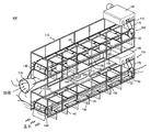
- FIG. 1 is a perspective view showing a wind and tidal power line according to a preferred embodiment of the present invention.
- Figure 2 (a), (b) is a view for explaining a wind power generator rotated left and right according to the direction of the wind, according to a preferred embodiment of the present invention.
- FIG. 1 is a view for explaining a wind power tidal power line according to a preferred embodiment of the present invention.
- the present invention 400 is largely composed of the tidal hydroelectric generator 100, the central shaft 200, the wind turbine 300.
- the tide hydroelectric generator 100 is generated by using the difference between the tidal power, and is provided with a buoyancy body (not shown) that generates buoyancy is formed to float on the water.
- the tide hydroelectric generator 100 is a support body 110 and the pair of drive rollers 130, 130 'installed on both ends of the support body 110 to form an outer, so as to support the rotation, A pair of conveyor ropes 120 and 120 'wound around the driving rollers 130 and 130' and installed adjacent to each other, and a plurality of plates 140 hinged to the conveyor ropes 120 and 120 'at regular intervals; And a connection wire 150 connecting the conveyor rope 120 and the plate 140 between the plate 140 and the plate 140, and installed on the driving roller 130 and the support body 110. It consists of a power transmission belt 170 connecting the generator 160 to each other.
- the support body 110 may be referred to as a frame forming the overall outline.
- the conveyor rope 120 is installed in the support body 110 in a flow length direction, and is wound on and supported by a pair of driving rollers 130 and 130 'installed at both ends of the support body 110.
- the plurality of plates 140 are attached to the conveyor rope 120 at regular intervals and are coupled by hinge coupling.
- connection wire 150 serves to connect the conveyor rope 120 and the plate 140 to prevent the plate 140 from being flipped more than 90 degrees.
- connection wire 150 is connected to the plate 140, it is preferable to be connected to the lower side of the plate 140 to prevent the twist or derailment of the plate 140.
- both sides of the lower plate 140 is connected to the conveyor rope 120 by the connection wire 150, respectively, so that the plate 140 is not twisted or derailed to one side.
- connection wire 150 is preferably made of a rigid material such as iron wire that is not easily broken or worn.
- the power transmission belt 170 is a belt for transmitting the power generated by the conveyor rope 120 to the generator 160, serves to convert the rotational force into electrical energy.
- the central shaft 200 is mounted on the support plate 210 formed on the top of the tidal hydroelectric generator 100, and is supported by rotation by a bearing (not shown).
- the bearing plate 210 is accommodated in a bearing (not shown), the central axis 200 is rolling by the bearing, so less friction and easy rotation.
- the upper end of the central axis is provided with a wind turbine to be described later, so that the wind turbine is rotated according to the direction of the wind.
- the wind power generator 300 is generated by using wind power, is fixed to the upper end of the central axis 200 is rotatable according to the direction of the wind.
- the wind power generator 300 the support body 110 to form an outer, a pair of drive rollers 130, 130 'installed on both ends of the support body 110, so that the rotation is supported, A pair of conveyor ropes 120 and 120 'wound around the drive rollers 130 and 130' and installed next to each other, and a plurality of plates 140 hinged to the conveyor ropes 120 at regular intervals; , A connection wire 150 connecting the conveyor rope 120 and the plate 140 between the plate 140 and the plate 140, and a generator installed in the driving roller 130 and the support body 110. It consists of a power transmission belt 170 connecting the 160.
- Each plate 140 rotates the conveyor rope 120 by receiving resistance when wind blows from the front surface.
- the plate 140 does not bend or twist more than 90 degrees.
- wind collecting port 310 is installed on the front side of the wind power generator 300, so that the wind is collected in one place.
- And plate 140 forms a through hole (not shown) in the center, so that the wind passing through the plate 140 of the front end is transmitted to the rear plate 140 to increase the power generation efficiency.
- FIGS. 2A and 2B are plan views illustrating a wind turbine that rotates according to wind.
- the position where the central shaft is installed the distance from the front end of the wind turbine 100 to the central shaft 200, the rear end of the wind turbine 100 from the central shaft 200 Where it is formed shorter than the distance, approximately one third of the length of the wind turbine is preferable.
- the length of h2 is formed longer than h1, so that the number of plates attached to h2 is relatively larger.
- the h2 part is more wind-resistant and moves more toward the other side.
- the wind tidal power generation line of the present invention can adjust the direction according to the wind blowing direction.
- Floating wind power generation line 400 of the present invention is floating in the water flow.
- the flowing water rotates the conveyor rope 120 while pushing the plate 140 attached to the conveyor rope 120 of the tidal hydroelectric generator 100.
- Power is transmitted to the generator 160 connected to the conveyor rope 120 by this rotational force to convert the flowing energy into mechanical energy.
- the wind blowing in the air is collected by the wind collecting port 310 to rotate the conveyor rope 120 while pushing the plate 140 attached to the conveyor rope 120 of the wind power generator (300).
- This rotational force is transmitted to the generator 160 to convert the wind energy into mechanical energy.
- the wind power generating line 400 to supply power on its own, the direction is adjusted according to the wind blowing direction is self-driving.
- the present invention can be used for wind and tidal power generation lines, and more specifically, can be used for wind and tidal power generation lines sailing while supplying electric power by using wind and tidal power.
Landscapes
- Engineering & Computer Science (AREA)
- Chemical & Material Sciences (AREA)
- Combustion & Propulsion (AREA)
- Mechanical Engineering (AREA)
- General Engineering & Computer Science (AREA)
- Life Sciences & Earth Sciences (AREA)
- Aviation & Aerospace Engineering (AREA)
- Sustainable Development (AREA)
- Sustainable Energy (AREA)
- Ocean & Marine Engineering (AREA)
- Power Engineering (AREA)
- General Life Sciences & Earth Sciences (AREA)
- Oceanography (AREA)
- Hydraulic Turbines (AREA)
- Other Liquid Machine Or Engine Such As Wave Power Use (AREA)
Abstract
본 발명은 조수 간만의 차이를 이용하여 발전하며, 부력을 발생시키는 부력체가 구비되어 물 위에 뜨도록 형성된 조수 수력 발전장치와; 상기 조수 수력 발전장치의 상단에 형성된 받침판에 장착되어, 베어링에 의해 회전지지되는 중심축과; 풍력을 이용하여 발전하며, 상기 중심축의 상단에 형성되어 바람의 방향에 따라 회전가능한 풍력 발전장치; 로 이루어지되, 상기 풍력발전장치의 전단에서 중심축에 이르는 거리는, 상기 중심축에서 상기 풍력발전장치의 후단에 이르는 거리보다 짧게 형성됨을 특징으로 한다.
Description
본 발명은 풍·조력 발전선에 관한 것으로, 보다 상세하게는 풍력과 조력을 이용하여 스스로 전력을 충당하면서 항해하는 풍·조력 발전선에 관한 것이다.
일반적으로 자연력을 이용하여 전기를 생산하는 발전방법에는 수력발전, 풍력발전, 화력발전 등이 있다.
그 중에서 조수간만의 차이로 인하여 유속이 빠른 바다나, 강 등에 유속을 이용하여 발전을 하는 수력발전 장치들이 다수 제안되고 있다.
대한민국 공개특허공보 제10-2008-0054321호(발명의 명칭: 저속 수력이용 장치의 구조)에서는 한 쌍의 콘베어 롤러, 90도로 구동하는 장석형식의 저항판이 다수 장착된 콘베어 로프, 콘베어 롤러에 연결된 체인로프, 증속기에 연결된 커플링과 커플링과 연결된 발전기로 구성되는 수력이용 장치를 제시하고 있다.
그리고, 대한민국 공개특허공보 제2001-78479호(발명의 명칭: 해류를 이용한 발전기(70))에서는 다수의 파워보드가 장착된 로드레일, 로울러에 연결된 증감속기, 증감속기와 연결된 발전기로 구성되는 것을 특징으로 하는 발전기를 제시하고 있다.
그러나 상기 종래의 발명은 흐르는 물 위에 띄워진 물체와 물의 흐름 사이에서 일어나는 저항값을 이용하여 전기를 발전시켰으나. 대부분 느린 유속에 의하여 발전효율이 떨어졌다.
그리고 저항판이나 보드판이 물 흐름의 전면측에서 저항을 받는 경우 유속에 의한 탈선, 비틀림, 슬림 현상으로 90도 이상 회전하여 동력이 손실되는 문제점이 있었으며, 저항판이 단단히 고정되지 않은 경우에 빠른 유속으로 인하여 저항판이 파손되는 위험이 있었다.
그리고 종래에는 풍력을 이용하여 발전을 하는 풍력발전장치들도 다수 제안되어 왔다.
그러나 종래의 풍력 발전장치들은 풍차를 회전시키는 회전 모멘트가 작아서 발전 효율이 낮으며, 약풍 하에서는 풍차의 공력(空力:헛되이 들이는 힘)이 강하기 때문에, 기동을 위해서는 별도의 동력을 필요로 한다는 문제가 있었다.
본 발명은 상기 문제점을 해결하기 위해 안출된 것으로서, 본 발명의 해결하고자 하는 과제는, 흐르는 물 위에 발전선을 띄워서 조력과 풍력을 동시에 이용함으로써 발전효율을 높이도록 하는 풍·조력 발전선을 제공하고자 하는 데에 그 목적이 있다.
또한, 본 발명에서 사용되는 플레이트는 유수에 의한 저항이나 강풍에도 비틀림 현상이나 슬림 현상이 적어서 동력의 손실을 최소화하도록 하는 풍·조력 발전선을 제공하고자 하는 데에 그 목적이 있다.
마지막으로 본 발명은 바람이 부는 방향에 따라 배의 방향 조절이 자체적으로 가능하고, 스스로 전력을 충당할 수 있으므로 자가운행이 가능한 풍·조력 발전선을 제공하고자 하는 데에 그 목적이 있다.
상기의 목적을 달성하기 위해 본 발명은 조수 간만의 차이를 이용하여 발전하며, 부력을 발생시키는 부력체가 구비되어 물 위에 뜨도록 형성된 조수 수력 발전장치와, 상기 조수 수력 발전장치의 상단에 형성된 받침판에 장착되어, 베어링에 의해 회전지지되는 중심축과, 풍력을 이용하여 발전하며, 상기 중심축의 상단에 형성되어 바람의 방향에 따라 회전가능한 풍력 발전장치로 이루어지되, 상기 풍력발전장치의 전단에서 중심축에 이르는 거리는, 상기 중심축에서 상기 풍력발전장치의 후단에 이르는 거리보다 짧게 형성됨을 특징으로 한다.
여기서, 상기 조수 수력 발전장치는 외곽을 형성하는 지지대 몸체와, 상기 지지대 몸체의 양단에 설치된 한 쌍의 구동롤러와, 회전지지되도록, 상기 구동롤러에 권취되며, 서로 이웃하게 나란히 설치된 한 쌍의 컨베이어 로프와, 상기 컨베이어 로프에, 일정한 간격으로 이격되게 힌지 결합하는 다수개의 플레이트와, 상기 플레이트와 플레이트 사이에 있는, 컨베이어 로프와 상기 플레이트 사이를 이어주는 연결 와이어와, 상기 구동롤러와 지지대 몸체에 설치된 발전기를 서로 연결하는 동력전달벨트로 이루어지는 것이 바람직하다.
그리고 상기 풍력발전장치는 외곽을 형성하는 지지대 몸체와, 상기 지지대 몸체의 양단에 설치된 한 쌍의 구동롤러와, 회전지지되도록, 상기 구동롤러에 권취되며, 서로 이웃하게 나란히 설치된 한 쌍의 컨베이어 로프와, 상기 컨베이어 로프에, 일정한 간격으로 이격되게 힌지 결합하는 다수개의 플레이트와, 상기 플레이트와 플레이트 사이에 있는 컨베이어 로프와 상기 플레이트 사이를 이어주는 연결 와이어와, 상기 구동롤러와 지지대 몸체에 설치된 발전기를 서로 연결하는 동력전달벨트로 이루어지는 것을 특징으로 한다.
또한, 상기 중심축은 상기 풍력발전장치 길이의 1/3 지점에 위치함을 특징으로 한다.
그리고 상기 플레이트는 가운데에 관통홀이 형성되어, 상기 관통홀을 통과한 바람이 후단의 플레이트에 전달됨을 특징으로 한다.
또한, 상기 풍력발전장치는 바람을 한곳으로 수집하는 바람수집구를 더 구비하는 것을 특징으로 한다.
상기와 같은 구성의 본 발명에 따르면, 다음과 같은 효과를 기대할 수 있을 것이다.
우선, 조력과 풍력을 동시에 이용하여 에너지를 창출하므로 발전 효율이 높은 효과가 있다.
또한, 빠른 유속이나 강풍 등으로 인하여 큰 저항을 받는 경우에도 플레이트의 탈선이나 비틀림 현상을 방지하여 동력손실을 예방하는 효과가 있다.
또한, 흐르는 물 위에서 배의 방향조절과 전력 충당이 자체적으로 이루어지므로 자가 발전 선박으로 유용한 효과가 있다.
마지막으로, 흐르는 물 위에서는 어디든지 장착될 수 있으며, 단기간에 설치할 수 있고 설치 공간이 많이 차지하지 않아 설치 비용을 감소시키는 효과가 있다.
도1 은 본 발명의 바람직한 실시예에 따른, 풍·조력 발전선을 나타내는 사시도이다.
도 2(a),(b)는 본 발명의 바람직한 실시예에 따른, 바람의 방향에 따라 좌우로 회전되는 풍력발전장치를 설명하기 위한 도면이다.
- 부호의 설명 -
100: 조수 수력 발전장치
110: 지지대 몸체
120,120'; 컨베이어 로프
130: 구동롤러
140,140': 플레이트
150,150': 연결와이어
160: 발전기
170: 동력전달벨트
200: 중심축
210: 받침판
300: 풍력발전장치
310: 바람수집구
400: 풍·조력발전선
이하, 첨부된 도면을 참조로 하여 본 발명의 풍·조력 발전선을 보다 상세히 설명하기로 한다.
도 1은 본 발명의 바람직한 실시예에 따른 풍·조력 발전선을 설명하기 위한 도면이다.
도시된 바와 같이 본 발명(400)은 크게, 조수 수력 발전장치(100), 중심축(200), 풍력 발전장치(300)로 이루어진다.
먼저 조수 수력 발전장치(100)에 대해 설명하고자 한다.
상기 조수 수력 발전장치(100)는 조수 간만의 차이를 이용하여 발전하며, 부력을 발생시키는 부력체(미도시)구비되어 물 위에 뜨도록 형성된다.
보다 상세하게 살펴보면, 조수 수력 발전장치(100)는 외곽을 형성하는 지지대 몸체(110)와, 상기 지지대 몸체(110)의 양단에 설치된 한 쌍의 구동롤러(130,130')와, 회전지지되도록, 상기 구동롤러(130,130')에 권취되며, 서로 이웃하게 나란히 설치된 한 쌍의 컨베이어 로프(120,120')와, 상기 컨베이어 로프(120,120')에, 일정한 간격으로 이격되게 힌지 결합하는 다수개의 플레이트(140)와, 상기 플레이트(140)와 플레이트(140) 사이에 있는, 컨베이어 로프(120)와 상기 플레이트(140) 사이를 이어주는 연결 와이어(150)와, 상기 구동롤러(130)와 지지대 몸체(110)에 설치된 발전기(160)를 서로 연결하는 동력전달벨트(170)로 이루어진다.
여기서 지지대 몸체(110)는 전체적인 외곽을 이루는 프레임이라 할 수 있다.
그리고 컨베이어 로프(120)는 지지대 몸체(110)에 유수길이 방향으로 설치되며, 지지대 몸체(110)의 양단에 설치된 한쌍의 구동롤러(130,130')에 권취되어 회전지지된다.
상기 다수개의 플레이트(140)는 상기 컨베이어 로프(120)에 일정간격으로 다수 개가 부착되며 힌지결합으로 결합되어 있다.
특히, 상기 연결 와이어(150)는 상기 컨베이어 로프(120)와 상기 플레이트(140) 사이를 연결하여 상기 플레이트(140)가 90도 이상으로 젖혀지는 것을 방지하는 역할을 한다.
이러한 연결 와이어(150)는 플레이트(140)에 연결되되, 상기 플레이트(140)의 하부측에 연결되는 것이 플레이트(140)의 비틀림이나 탈선을 예방하는 데에 바람직하다.
즉, 상기 플레이트(140) 하부의 양측은 각각 연결 와이어(150)에 의하여, 컨베이어 로프(120)에 연결되어 지지되므로, 플레이트(140)가 일측으로 비틀리거나 탈선되지 않게 된다.
상기 연결 와이어(150)은 쉽게 끊어지거나, 마모되지 않는 철선 등의 강성의 재질로 이루어지는 것이 바람직하다.
그리고 상기 동력전달벨트(170)는 컨베이어 로프(120)에 의해서 발생된 동력을 발전기(160)에 전달하는 벨트로써, 회전력을 전기에너지로 변환시키는 역할을 한다.
다음은 중심축(200)에 대해 설명하고자 한다.
상기 중심축(200)은 상기 조수 수력 발전장치(100)의 상단에 형성된 받침판(210)에 장착되어, 베어링(미도시)에 의해 회전지지된다.
상기 받침판(210)에는 베어링(미도시)이 수용되어, 상기 중심축(200)은 베어링에 의해 구름 운동하므로 마찰이 적고 회전이 용이하게 된다.
이러한 중심축의 상단에는 후술할 풍력발전장치가 설치되어, 바람의 방향에 따라 상기 풍력발전장치가 회전되도록 한다.
다음은 풍력발전장치(300)에 대해 설명하고자 한다.
상기 풍력발전장치(300)는 풍력을 이용하여 발전하며, 상기 중심축(200)의 상단에 고정형성되어 바람의 방향에 따라 회전가능하다.
보다 상세하게 살펴보면, 상기 풍력발전장치(300)는, 외곽을 형성하는 지지대 몸체(110)와, 상기 지지대 몸체(110)의 양단에 설치된 한 쌍의 구동롤러(130,130')와, 회전지지되도록, 상기 구동롤러(130,130')에 권취되며, 서로 이웃하게 나란히 설치된 한 쌍의 컨베이어 로프(120,120')와, 상기 컨베이어 로프(120)에, 일정한 간격으로 이격되게 힌지 결합하는 다수개의 플레이트(140)와, 상기 플레이트(140)와 플레이트(140) 사이에 있는, 컨베이어 로프(120)와 상기 플레이트(140) 사이를 이어주는 연결 와이어(150), 상기 구동롤러(130)와 지지대 몸체(110)에 설치된 발전기(160)를 연결하는 동력전달벨트(170)로 이루어진다.
상기 각 플레이트(140)는 전면에서 바람이 불어오면 저항을 받아 컨베이어 로프(120)를 회전시킨다.
이때 플레이트(140)의 양측은 연결 와이어(150)에 의해 컨베이어 로프(120)와 연결되어 있으므로 90도 이상 휘어지거나 비틀림 현상이 일어나지 않는다.
여기서 상기 지지대 몸체(110), 구동롤러(130), 컨베이어 로프(120), 플레이트(140),발전기(160), 동력전달밸트(170)에 대한 설명은 조수 수력 발전장치(100)에서 설명하였는바, 여기서의 설명은 생략하기로 한다.
그리고 상기 풍력발전 장치(300)의 전측에는 바람수집구(310)가 설치되어, 바람이 한곳으로 수집되도록 한다.
그리고 플레이트(140)는 가운데에 관통홀(미도시)을 형성하여, 전단의 플레이트(140)를 통과한 바람이 후단 플레이트(140)에 전달되도록 하여 발전효율을 높이도록 한다.
다음으로 도2(a)와 도2(b)는 바람에 따라 회전하는 풍력발전장치를 나타내는 평면도이다.
도시된 바에 따르면, 중심축이 설치되는 위치는, 상기 풍력 발전장치(100)의 전단에서 중심축(200)까지의 거리가, 상기 중심축(200)에서 상기 풍력 발전장치(100)의 후단에 이르는 거리보다 짧게 형성되는 곳으로, 대략 풍력발전장치 길이의 1/3 지점이 바람직하다.
즉, h1보다 h2의 길이가 더 길게 형성되어, 상대적으로 h2에 부착된 플레이트 수가 더 많게 된다.
그리하여 h2 부분이 바람에 의한 저항을 많이 받게 되어 반대편으로 더 많이 이동한다.
따라서, 도2(a)와 같이 바람이 우측에서 불어오면, 풍력발전장치는 전단보다 후단이 좌측으로 더 많이 이동하여, 상대적으로 머리부분이 우측을 향하게 된다.
그리고 도2(b)와 같이 바람이 좌측에서 불어오면, 풍력발전장치(300)는 전단보다 후단이 우측으로 더 많이 이동하여, 상대적으로 머리부분이 좌측을 향하게 된다.
이와 같이, 본 발명의 풍조력 발전선은 바람이 부는 방향에 따라 스스로 방향조절이 가능하다.
다음은 본 발명의 적용례에 대해 살펴본다.
본 발명의 풍조발전선(400)을 물이 흐르는 곳에 띄어둔다.
흐르는 물은 조수 수력 발전장치(100)의, 컨베이어 로프(120)에 부착된 플레이트(140)를 밀어내면서, 상기 컨베이어 로프(120)를 회전시킨다.
이러한 회전력으로 컨베이어 로프(120)에 연결된 발전기(160)에 동력이 전달되어 유수에너지를 기계에너지로 변환시킨다.
이때 상기 플레이트(140)는 연결 와이어(150)에 의해 지지되므로, 물의 저항을 받을 때에도 뒤로 접혀짐이 수직으로 유지된다.
그리고 공기 중에 부는 바람은 바람수집구(310)에 의해 한곳을 수집되어 풍력발전장치(300)의, 컨베이어 로프(120)에 부착된 플레이트(140)를 밀어내면서 컨베이어 로프(120)를 회전시킨다.
이러한 회전력이 발전기(160)에 전달되어 풍력 에너지가 기계에너지로 변환된다.
이와 같이 풍조발전선(400)을 흐르는 물위에서 스스로 전력을 충당하며, 바람이 부는 방향에 따라 방향이 조절되어 자가운행한다.
이상에서 설명한 본 발명은 흐르는 물 위에 발전선을 띄워서 조력과 풍력을 동시에 이용함으로써 발전효율을 높이도록 하는 풍·조력 발전선을 제공하는 것을 기본적인 기술적인 사상으로 하고 있음을 알 수 있으며, 이와 같은 본 발명의 기본적인 사상의 범주내에서, 당업계의 통상의 지식을 가진 자에게 있어서는 다른 많은 변형이 가능함은 물론이다.
본 발명은 풍·조력 발전선에 이용 가능한 것으로, 보다 상세하게는 풍력과 조력을 이용하여 스스로 전력을 충당하면서 항해하는 풍·조력 발전선에 이용 가능한 것이다.
Claims (6)
- 조수 간만의 차이를 이용하여 발전하며, 부력을 발생시키는 부력체가 구비되어 물 위에 뜨도록 형성된 조수 수력 발전장치와;상기 조수 수력 발전장치의 상단에 형성된 받침판에 장착되어, 베어링에 의해 회전지지되는 중심축과;풍력을 이용하여 발전하며, 상기 중심축의 상단에 형성되어 바람의 방향에 따라 회전가능한 풍력 발전장치;로 이루어지되, 상기 풍력발전장치의 전단에서 중심축에 이르는 거리는, 상기 중심축에서 상기 풍력발전장치의 후단에 이르는 거리보다 짧게 형성됨을 특징으로 하는 풍·조력 발전선.
- 제1항에 있어서,상기 조수 수력 발전장치는,외곽을 형성하는 지지대 몸체와, 상기 지지대 몸체의 양단에 설치된 한 쌍의 구동롤러와, 회전지지되도록, 상기 구동롤러에 권취되며, 서로 이웃하게 나란히 설치된 한 쌍의 컨베이어 로프와, 상기 컨베이어 로프에, 일정한 간격으로 이격되게 힌지 결합하는 다수개의 플레이트와, 상기 플레이트와 플레이트 사이에 있는 컨베이어 로프와 상기 플레이트 사이를 이어주는 연결 와이어와, 상기 구동롤러와 지지대 몸체에 설치된 발전기를 서로 연결하는 동력전달벨트로 이루어지는 것을 특징으로 하는 풍·조력 발전선.
- 제1항에 있어서,상기 풍력발전장치는,외곽을 형성하는 지지대 몸체와, 상기 지지대 몸체의 양단에 설치된 한 쌍의 구동롤러와, 회전지지되도록, 상기 구동롤러에 권취되며, 서로 이웃하게 나란히 설치된 한 쌍의 컨베이어 로프와, 상기 컨베이어 로프에, 일정한 간격으로 이격되게 힌지 결합하는 다수개의 플레이트와, 상기 플레이트와 플레이트 사이에 있는 컨베이어 로프와 상기 플레이트 사이를 이어주는 연결 와이어와, 상기 구동롤러와 지지대 몸체에 설치된 발전기를 서로 연결하는 동력전달벨트로 이루어지는 것을 특징으로 하는 풍·조력 발전선.
- 제1항에 있어서,상기 중심축은,상기 풍력발전장치 길이의 1/3 지점에 위치함을 특징으로 하는 풍·조력 발전선.
- 제3항에 있어서,상기 플레이트는,가운데에 관통홀이 형성되어, 상기 관통홀을 통과한 바람이 후단의 플레이트에 전달됨을 특징으로 하는 풍·조력 발전선.
- 제3항에 있어서,상기 풍력발전장치는,바람을 한곳으로 수집하는 바람수집구를 더 구비하는 것을 특징으로 하는 풍·조력 발전선.
Priority Applications (1)
| Application Number | Priority Date | Filing Date | Title |
|---|---|---|---|
| US13/286,492 US8344540B2 (en) | 2010-06-28 | 2011-11-01 | Wind and water power generator ship |
Applications Claiming Priority (2)
| Application Number | Priority Date | Filing Date | Title |
|---|---|---|---|
| KR1020100061144A KR101138377B1 (ko) | 2010-06-28 | 2010-06-28 | 풍?조력 발전선 |
| KR10-2010-0061144 | 2010-07-28 |
Related Child Applications (1)
| Application Number | Title | Priority Date | Filing Date |
|---|---|---|---|
| US13/286,492 Continuation US8344540B2 (en) | 2010-06-28 | 2011-11-01 | Wind and water power generator ship |
Publications (1)
| Publication Number | Publication Date |
|---|---|
| WO2012002607A1 true WO2012002607A1 (ko) | 2012-01-05 |
Family
ID=45402295
Family Applications (1)
| Application Number | Title | Priority Date | Filing Date |
|---|---|---|---|
| PCT/KR2010/005295 Ceased WO2012002607A1 (ko) | 2010-06-28 | 2010-08-12 | 풍·조력 발전선 |
Country Status (3)
| Country | Link |
|---|---|
| US (1) | US8344540B2 (ko) |
| KR (1) | KR101138377B1 (ko) |
| WO (1) | WO2012002607A1 (ko) |
Families Citing this family (8)
| Publication number | Priority date | Publication date | Assignee | Title |
|---|---|---|---|---|
| US9689369B2 (en) * | 2012-02-17 | 2017-06-27 | Joseph Sieber | Endless belt energy converter |
| US8890353B2 (en) * | 2012-05-22 | 2014-11-18 | Frank Patrick Cunnane | Power generating hydroconveyor |
| KR101334635B1 (ko) | 2012-08-07 | 2013-12-02 | 삼성중공업 주식회사 | 플레이트 타입 풍력 발전 장치 및 플레이트 타입 풍력 발전 장치가 설치된 건물 |
| US10415536B2 (en) * | 2013-12-31 | 2019-09-17 | Chong Hun Kim | Moving window frame with multiple windows and its application in the ocean, river, and wind |
| JP5652929B1 (ja) * | 2014-07-09 | 2015-01-14 | 良輔 三澤 | 風力発電装置 |
| US10837421B2 (en) * | 2017-07-13 | 2020-11-17 | Yong Soo Cho | Tidal current power generator |
| KR101851909B1 (ko) | 2017-11-27 | 2018-06-29 | 노아신재생에너지 주식회사 | 선박을 이용한 조력발전장치 |
| KR20190065559A (ko) | 2017-12-04 | 2019-06-12 | 이성암 | 원호날개 유체통로 발전터빈 |
Citations (4)
| Publication number | Priority date | Publication date | Assignee | Title |
|---|---|---|---|---|
| KR20010078479A (ko) * | 2001-03-14 | 2001-08-21 | 곽양진 | 해류를 이용한 발전기 |
| KR20080054321A (ko) * | 2006-12-12 | 2008-06-17 | 김영생 | 저속 수력이용 장치의 구조 |
| JP2009073455A (ja) * | 2007-09-20 | 2009-04-09 | Kenichiro Kato | 玄武船による海流発電新工法。 |
| KR20090097089A (ko) * | 2008-03-10 | 2009-09-15 | 곽양진 | 유속 발전장치 |
Family Cites Families (2)
| Publication number | Priority date | Publication date | Assignee | Title |
|---|---|---|---|---|
| US4346305A (en) * | 1976-11-30 | 1982-08-24 | White Forest B | Governor for fluid current motor |
| US8206106B2 (en) * | 2006-11-16 | 2012-06-26 | Windflo, Llc | Oscillating windmill |
-
2010
- 2010-06-28 KR KR1020100061144A patent/KR101138377B1/ko not_active Expired - Fee Related
- 2010-08-12 WO PCT/KR2010/005295 patent/WO2012002607A1/ko not_active Ceased
-
2011
- 2011-11-01 US US13/286,492 patent/US8344540B2/en not_active Expired - Fee Related
Patent Citations (4)
| Publication number | Priority date | Publication date | Assignee | Title |
|---|---|---|---|---|
| KR20010078479A (ko) * | 2001-03-14 | 2001-08-21 | 곽양진 | 해류를 이용한 발전기 |
| KR20080054321A (ko) * | 2006-12-12 | 2008-06-17 | 김영생 | 저속 수력이용 장치의 구조 |
| JP2009073455A (ja) * | 2007-09-20 | 2009-04-09 | Kenichiro Kato | 玄武船による海流発電新工法。 |
| KR20090097089A (ko) * | 2008-03-10 | 2009-09-15 | 곽양진 | 유속 발전장치 |
Also Published As
| Publication number | Publication date |
|---|---|
| US8344540B2 (en) | 2013-01-01 |
| KR101138377B1 (ko) | 2012-04-26 |
| KR20120000726A (ko) | 2012-01-04 |
| US20120043764A1 (en) | 2012-02-23 |
Similar Documents
| Publication | Publication Date | Title |
|---|---|---|
| WO2012002607A1 (ko) | 풍·조력 발전선 | |
| WO2013095033A1 (ko) | 나셀 펜스를 갖는 풍력발전기 | |
| WO2014025124A1 (ko) | 풍력발전장치 | |
| WO2017086693A1 (ko) | 중력과 부력을 이용한 자가 발전장치 및 구조물을 이용한 자가 발전장치 그리고 이를 이용한 해양 경계등 | |
| WO2012102433A1 (ko) | 조류 발전 장치 | |
| WO2015156613A1 (ko) | 수상태양광 발전장치 부유 구조물 및 구조물간의 연결방법 | |
| WO2012030051A1 (ko) | 수차 및 이를 이용한 수력발전 구조물 | |
| WO2010134690A2 (ko) | 수직축 풍차용 회전 조립체 | |
| WO2012011645A1 (ko) | 파력발전장치 | |
| CN108069526A (zh) | 太阳能风力双发电水生态修复曝气设备 | |
| WO2013115581A1 (ko) | 파력발전장치 | |
| CN104265550A (zh) | 一种漂浮式波浪能发电系统 | |
| WO2011102638A2 (ko) | 회전동력 발생기 및 이를 이용한 구심력 동작형 수차 | |
| WO2017204437A1 (ko) | 조류 발전기 | |
| WO2013089398A1 (ko) | 해류 또는 조류를 이용하는 발전장치 | |
| WO2016085065A1 (ko) | 부유식 해상 풍력발전설비 | |
| WO2011025343A2 (ko) | 기구 풍력 집중식 발전기 | |
| WO2016060498A1 (ko) | 스크린 파력 발전장치 | |
| WO2010143922A2 (ko) | 하수처리장 방류수 및 정수장 유출수를 이용한 부유식 소수력 발전장치 | |
| WO2017090790A1 (ko) | 부유식 발전장치 및 이를 갖는 복합 발전시스템 | |
| WO2013065987A2 (ko) | 공중 풍력 발전 시스템 | |
| WO2012087064A2 (ko) | 조류발전장치 | |
| WO2013109007A1 (ko) | 풍력발전장치 | |
| WO2010117173A2 (ko) | 파력 발전 장치 | |
| WO2014084493A1 (ko) | 수력, 자력 및 풍력을 이용한 발전장치 |
Legal Events
| Date | Code | Title | Description |
|---|---|---|---|
| 121 | Ep: the epo has been informed by wipo that ep was designated in this application |
Ref document number: 10854153 Country of ref document: EP Kind code of ref document: A1 |
|
| NENP | Non-entry into the national phase |
Ref country code: DE |
|
| 122 | Ep: pct application non-entry in european phase |
Ref document number: 10854153 Country of ref document: EP Kind code of ref document: A1 |