WO2012005037A1 - 固定部材 - Google Patents
固定部材 Download PDFInfo
- Publication number
- WO2012005037A1 WO2012005037A1 PCT/JP2011/058998 JP2011058998W WO2012005037A1 WO 2012005037 A1 WO2012005037 A1 WO 2012005037A1 JP 2011058998 W JP2011058998 W JP 2011058998W WO 2012005037 A1 WO2012005037 A1 WO 2012005037A1
- Authority
- WO
- WIPO (PCT)
- Prior art keywords
- plate
- module
- piece
- fixing member
- lower piece
- Prior art date
- Legal status (The legal status is an assumption and is not a legal conclusion. Google has not performed a legal analysis and makes no representation as to the accuracy of the status listed.)
- Ceased
Links
Images



Classifications
-
- F—MECHANICAL ENGINEERING; LIGHTING; HEATING; WEAPONS; BLASTING
- F16—ENGINEERING ELEMENTS AND UNITS; GENERAL MEASURES FOR PRODUCING AND MAINTAINING EFFECTIVE FUNCTIONING OF MACHINES OR INSTALLATIONS; THERMAL INSULATION IN GENERAL
- F16M—FRAMES, CASINGS OR BEDS OF ENGINES, MACHINES OR APPARATUS, NOT SPECIFIC TO ENGINES, MACHINES OR APPARATUS PROVIDED FOR ELSEWHERE; STANDS; SUPPORTS
- F16M13/00—Other supports for positioning apparatus or articles; Means for steadying hand-held apparatus or articles
- F16M13/02—Other supports for positioning apparatus or articles; Means for steadying hand-held apparatus or articles for supporting on, or attaching to, an object, e.g. tree, gate, window-frame, cycle
-
- F—MECHANICAL ENGINEERING; LIGHTING; HEATING; WEAPONS; BLASTING
- F24—HEATING; RANGES; VENTILATING
- F24S—SOLAR HEAT COLLECTORS; SOLAR HEAT SYSTEMS
- F24S25/00—Arrangement of stationary mountings or supports for solar heat collector modules
- F24S25/60—Fixation means, e.g. fasteners, specially adapted for supporting solar heat collector modules
- F24S25/61—Fixation means, e.g. fasteners, specially adapted for supporting solar heat collector modules for fixing to the ground or to building structures
-
- F—MECHANICAL ENGINEERING; LIGHTING; HEATING; WEAPONS; BLASTING
- F24—HEATING; RANGES; VENTILATING
- F24S—SOLAR HEAT COLLECTORS; SOLAR HEAT SYSTEMS
- F24S25/00—Arrangement of stationary mountings or supports for solar heat collector modules
- F24S25/60—Fixation means, e.g. fasteners, specially adapted for supporting solar heat collector modules
- F24S25/63—Fixation means, e.g. fasteners, specially adapted for supporting solar heat collector modules for fixing modules or their peripheral frames to supporting elements
- F24S25/632—Side connectors; Base connectors
-
- F—MECHANICAL ENGINEERING; LIGHTING; HEATING; WEAPONS; BLASTING
- F24—HEATING; RANGES; VENTILATING
- F24S—SOLAR HEAT COLLECTORS; SOLAR HEAT SYSTEMS
- F24S25/00—Arrangement of stationary mountings or supports for solar heat collector modules
- F24S25/60—Fixation means, e.g. fasteners, specially adapted for supporting solar heat collector modules
- F24S25/63—Fixation means, e.g. fasteners, specially adapted for supporting solar heat collector modules for fixing modules or their peripheral frames to supporting elements
- F24S25/634—Clamps; Clips
-
- F—MECHANICAL ENGINEERING; LIGHTING; HEATING; WEAPONS; BLASTING
- F24—HEATING; RANGES; VENTILATING
- F24S—SOLAR HEAT COLLECTORS; SOLAR HEAT SYSTEMS
- F24S25/00—Arrangement of stationary mountings or supports for solar heat collector modules
- F24S25/60—Fixation means, e.g. fasteners, specially adapted for supporting solar heat collector modules
- F24S25/67—Fixation means, e.g. fasteners, specially adapted for supporting solar heat collector modules for coupling adjacent modules or their peripheral frames
-
- H—ELECTRICITY
- H02—GENERATION; CONVERSION OR DISTRIBUTION OF ELECTRIC POWER
- H02S—GENERATION OF ELECTRIC POWER BY CONVERSION OF INFRARED RADIATION, VISIBLE LIGHT OR ULTRAVIOLET LIGHT, e.g. USING PHOTOVOLTAIC [PV] MODULES
- H02S20/00—Supporting structures for PV modules
- H02S20/20—Supporting structures directly fixed to an immovable object
- H02S20/22—Supporting structures directly fixed to an immovable object specially adapted for buildings
- H02S20/23—Supporting structures directly fixed to an immovable object specially adapted for buildings specially adapted for roof structures
-
- Y—GENERAL TAGGING OF NEW TECHNOLOGICAL DEVELOPMENTS; GENERAL TAGGING OF CROSS-SECTIONAL TECHNOLOGIES SPANNING OVER SEVERAL SECTIONS OF THE IPC; TECHNICAL SUBJECTS COVERED BY FORMER USPC CROSS-REFERENCE ART COLLECTIONS [XRACs] AND DIGESTS
- Y02—TECHNOLOGIES OR APPLICATIONS FOR MITIGATION OR ADAPTATION AGAINST CLIMATE CHANGE
- Y02B—CLIMATE CHANGE MITIGATION TECHNOLOGIES RELATED TO BUILDINGS, e.g. HOUSING, HOUSE APPLIANCES OR RELATED END-USER APPLICATIONS
- Y02B10/00—Integration of renewable energy sources in buildings
- Y02B10/10—Photovoltaic [PV]
-
- Y—GENERAL TAGGING OF NEW TECHNOLOGICAL DEVELOPMENTS; GENERAL TAGGING OF CROSS-SECTIONAL TECHNOLOGIES SPANNING OVER SEVERAL SECTIONS OF THE IPC; TECHNICAL SUBJECTS COVERED BY FORMER USPC CROSS-REFERENCE ART COLLECTIONS [XRACs] AND DIGESTS
- Y02—TECHNOLOGIES OR APPLICATIONS FOR MITIGATION OR ADAPTATION AGAINST CLIMATE CHANGE
- Y02E—REDUCTION OF GREENHOUSE GAS [GHG] EMISSIONS, RELATED TO ENERGY GENERATION, TRANSMISSION OR DISTRIBUTION
- Y02E10/00—Energy generation through renewable energy sources
- Y02E10/40—Solar thermal energy, e.g. solar towers
- Y02E10/47—Mountings or tracking
-
- Y—GENERAL TAGGING OF NEW TECHNOLOGICAL DEVELOPMENTS; GENERAL TAGGING OF CROSS-SECTIONAL TECHNOLOGIES SPANNING OVER SEVERAL SECTIONS OF THE IPC; TECHNICAL SUBJECTS COVERED BY FORMER USPC CROSS-REFERENCE ART COLLECTIONS [XRACs] AND DIGESTS
- Y02—TECHNOLOGIES OR APPLICATIONS FOR MITIGATION OR ADAPTATION AGAINST CLIMATE CHANGE
- Y02E—REDUCTION OF GREENHOUSE GAS [GHG] EMISSIONS, RELATED TO ENERGY GENERATION, TRANSMISSION OR DISTRIBUTION
- Y02E10/00—Energy generation through renewable energy sources
- Y02E10/50—Photovoltaic [PV] energy
Definitions
- the present invention relates to a fixing member for fixing a plate-like module such as a solar water heater or a solar cell module installed on a roof or the like to the roof or the like.
- Patent Document 1 a concave shape formed on a side surface of a frame body in a solar cell module. A joined portion to be inserted into the joined portion, a shaft portion depending from the center of the joined portion, and a pedestal portion that is connected to the lower end of the shaft portion and on which the frame of the solar cell module is placed.
- a fixing member has been proposed.
- the frame on one end side of the solar cell module is supported on the pedestal portion and the joined portion of the fixing member in a state where the fixing member is attached to the mounting member such as a roof plate or a roof material, and the solar cell module
- the solar cell module can be fixed on a roof or the like by attaching another fixing member to the frame on the other end side of this and attaching the fixing member to the attachment member. Therefore, a plurality of solar cell modules can be sequentially fixed from one side (eave side) to the other side (building side), and the cost for installing the solar cell modules can be reduced.
- an engaged part is provided in the frame of a solar cell module.
- An engaging portion that engages is provided, and by moving the engaged portion to the engaging portion, the movement of the frame body in the direction away from the shaft portion can be restricted.
- the solar cell module arranged on the eave side also moves to the eave side (lower side) even with the fixing member that supports the ridge side (upper side) of the solar cell module. Since it can be prevented from moving, the load of the solar cell module can be supported by the eave-side and ridge-side fixing members, respectively.
- an object of the present invention is to provide a highly versatile fixing member that can reliably fix a plate module such as a solar cell module.
- the fixing member according to the present invention is “to be able to contact the upper surface of the plate module, or to be inserted into a groove formed on the side surface of the plate module, An extended upper piece, a shaft portion extending downward from the center of the upper piece, and a lower end of the shaft portion extending from the lower end to both sides larger than the upper piece, and being able to contact the lower surface of the plate module on the upper side
- a fixing member comprising at least a lower piece having a contact portion and an attachment hole formed on either side of the lower piece with the shaft portion interposed therebetween and penetrating in the vertical direction.
- the upper piece descends and the upper surface of the plate module or the upper portion of the groove And the abutting portion of the lower piece is a lower surface of the plate-like module It characterized the formed "it to abut.
- the “plate-like module” a solar cell module in which the outer periphery of the plate-like solar cell panel is surrounded by a frame”, “solar water heater panel”, “solar heat collecting panel”, “soundproof panel”, A “light-shielding panel” can be exemplified.
- the “mounting member” includes “roof material that forms the surface of the roof”, “a roof plate to which the roof material is attached”, “a roof structural member such as a rafter for forming the roof”, “a plate-like module” "Elongated beam member attached to the object to be installed”, “Fixing base attached to the object to install the plate module”, “Installation interposed between the object to install the plate module” Examples thereof include “metal fitting”, “wall surface”, “body edge for constituting the wall surface”, and the like.
- “Mounting the lower piece to the mounting member via the mounting hole” means “inserting a bolt or screw from the upper side of the lower piece into the mounting hole and pressing the lower piece to the mounting member side with the head of the bolt or the like. "Mount the male threaded part protruding from the mounting member side through the mounting hole from the lower side of the lower piece and press the lower piece to the mounting member side with a nut screwed into the male threaded part from the upper side of the lower piece.” For example, “attach and attach”.
- the “side surface of the plate module” includes a general side surface of the plate module and an end surface protruding from the general side surface.
- the state in which the side surface of the plate-shaped module is approached is a state in which the side surface of the plate-shaped module is positioned closer to the shaft portion than the center between the tip of the upper piece and the shaft portion. Is a state of being positioned closer to the shaft portion than 1 ⁇ 4 of the distance between the tip of the upper piece and the shaft portion. Thereby, a plate-shaped module can fully be clamped and fixed by the contact part of an upper piece and a lower piece.
- the upper piece when the lower piece is attached to the attachment member, the upper piece is lowered” means that “the bottom part of the lower piece is bent or bent so that the position directly below the shaft portion is lifted from the upper surface of the attachment member.
- the lower piece is deformed by attaching it to the attachment member, and the upper piece is lowered ”,“ Only the tip opposite to the attachment hole across the shaft portion of the lower piece is in contact with the attachment member, "Upper part is lowered by mounting so that the bottom surface of the piece generally follows the mounting member", “By providing protrusions projecting downward near both ends of the bottom surface of the lower piece, the mounting member is directly below the shaft portion.
- the lower piece is deformed and the upper piece is lowered by attaching the lower piece to the attachment member, and the like.
- the plate-like module is inserted between the upper piece and the lower piece on the opposite side of the mounting hole across the shaft portion of the fixing member, and the side surface of the plate-like module is brought into contact with or close to the shaft portion.
- the fixing member is placed on a mounting member such as a roofing material, and the lower piece is attached to the mounting member with screws, bolts, nuts, etc. through the mounting holes formed in the lower piece, the upper piece together with the shaft portion Since the plate module can be fixed by sandwiching the plate module in the vertical direction between the upper piece and the lower piece, the plate module may rattle or slide in the direction in which the fixing member extends. Can be prevented, and the plate-like module can be securely fixed.
- the plate-shaped module is inclined between the upper piece and the lower piece on the attachment hole side with the shaft portion sandwiched with the fixing member attached to the attachment member.
- the plate module can be fixed on the mounting hole side with the shaft portion interposed therebetween. Therefore, according to this fixing member, the plate-like module can be fixed to both sides with the shaft portion interposed therebetween, so that a plurality of plate-like modules can be fixed sequentially from one side to the other side, and the plate-like module is installed. It is possible to simplify the labor related to the installation and to reduce the cost related to the installation.
- the plate-like module can be sandwiched and fixed between the upper and lower contact portions of the fixing member, so that even when the plate-like module is installed in an inclined state,
- the fixed members fixed on the upper and lower sides of the module can support the load of the plate-like module, and the fixed member can be deformed or damaged by the uneven load by suppressing the load from being biased to only one of the fixed members. Can be prevented.
- the fixing member and the fixing member are engaged like the frame of the solar cell module described in Patent Document 1. Even if it does not have an engaging part for joining, if it is a plate-shaped module that can be sandwiched, it can be fixed securely by a fixing member, and it can be a highly versatile fixing member, and a special plate It is not necessary to use a plate-like module, a general (commercially available) plate-like module can be used, and the cost of the entire system using the plate-like module can be reduced.
- the fixing member is formed with a mounting hole at a position as close as possible to the shaft portion, so that the lower piece is screwed with a screw, a bolt, a nut, or the like through the mounting hole.
- the fixing strength of the plate module by the upper piece when attached to the attachment member can be increased, and the plate module can be more reliably fixed.
- the fixing member according to the present invention may be “in the state before being attached to the attachment member, the bottom surface of the lower piece is curved or bent so that the position directly below the shaft portion is the highest, and the attachment member It is good also as a structure which the said bottom face deform
- the bottom surface of the lower piece of the fixing member is curved or bent so that the position directly below the shaft portion is the highest, and when the fixing member is placed on the mounting member (the state before mounting), the shaft portion A gap is formed immediately below.
- the lower piece may be made thicker in the vertical direction as it is farther from the shaft, and the thickened tip may be used as a contact portion.
- the center of the plate (position of the shaft) is lowered, and the tip of the lower piece (contact portion) is relatively raised, so that the plate module can be sandwiched more strongly between the upper piece and the contact portion. It can be fixed securely.
- the fixing member according to the present invention has, in addition to the above-described configuration, “a through-hole formed on both sides across the shaft portion of the lower piece and penetrating vertically, and inserted into the through-hole from below,
- the structure may further include an auxiliary fixing portion having a piercing portion that pierces the lower surface of the plate-like module.
- the auxiliary fixing portion “the pierced portion inserted into the through-holes formed on both sides of the shaft portion are integrally connected below the lower piece”, “the shaft portion The piercing parts inserted into the through-holes formed on both sides with respect to each other are independent, "” The piercing parts respectively inserted into the through-holes formed on both sides with the shaft part interposed are under the lower piece. " And the like having a resilient portion that is integrally connected on the side and urges the bottom surface of the lower piece away from the mounting member.
- the piercing portion of the auxiliary fixing portion inserted into the through hole of the lower piece pierces the lower surface of the plate-like module, so that the plate-like module is also rattled or fixed by the auxiliary fixing portion. It is possible to prevent the member from sliding in the extending direction, and the plate-like module can be securely fixed.
- the auxiliary fixing part may be electrically connected to the lower part of the lower piece by integrally connecting the pierced parts respectively inserted into the through holes on both sides of the shaft part.
- the plate-like modules fixed on both sides of the shaft portion can be electrically connected through the fixing portion, and the ground connection between the plate-like modules can be easily performed.
- even a plate-shaped module having an insulating film on the surface can be broken by the pierced portion of the auxiliary fixing portion, and the plate-like modules such as the solar cell module can be reliably connected to each other. Can be connected to each other and grounded.
- a plate-like module such as a solar cell module can be reliably fixed, and a highly versatile fixing member can be provided.
- FIG. 1 A is explanatory drawing which shows the state before attaching a fixing member to an attachment member in FIG. 1
- B is explanatory drawing which shows the state which attached the fixing member to the attachment member and fixed one plate-shaped module.
- C is an explanatory view showing a state in which the plate-like module is fixed on both sides of the shaft portion of the fixing member.
- A) is sectional drawing shown in the state before attaching the fixing member of other embodiment to an attachment member
- (B) is sectional drawing shown in the state which attached the fixing member of (A) to the attachment member.
- FIG. (A) is sectional drawing shown in the state before attaching still another embodiment of the fixing member which concerns on this invention to an attachment member
- (B) is a cross section shown in the state which attached the fixing member of (A) to the attachment member.
- FIG. (A) is sectional drawing shown in the state before attaching the fixing member of another embodiment to an attachment member
- (B) is sectional drawing shown in the state which attached the fixing member of (A) to the attachment member.
- (A) is sectional drawing shown in the state before attaching the fixing member of another embodiment to an attachment member
- (B) is sectional drawing shown in the state which attached the fixing member of (A) to the attachment member.
- (A) is sectional drawing shown in the state before attaching the fixing member of another embodiment to an attachment member
- (B) is sectional drawing shown in the state which attached the fixing member of (A) to the attachment member. Furthermore, it is sectional drawing shown in the state which attached the fixing member of different embodiment to the attachment member.
- a fixing member according to an embodiment of the present invention will be described in detail with reference to FIGS. 1 to 3 (A) to (C).
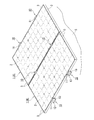
- the fixing member 10 of the present embodiment attaches a plate-like module 1 such as a solar cell module 4 in which the outer periphery of the plate-like solar cell panel 2 is surrounded by a frame 3 to a roof material or the like. It is for installation on the member 5 and is attached to the attachment member 5 by a predetermined fastening member 6 such as a screw or a bolt.
- the fixing member 10 of this example can be brought into contact with the upper surface of the plate-like module 1, and has an upper piece 11 that extends in the left-right direction, a shaft portion 12 that extends downward from the center of the upper piece 11, and a shaft portion 12.
- the fixing member 10 has an upper piece 11 and a lower piece 13 that extend substantially equally to the left and right with the shaft portion 12 interposed therebetween, and is formed in a substantially letter E shape with a short upper side when viewed from the longitudinal direction.
- the fixing member 10 includes a recess 15 that can accommodate the head of the fastening member 6 that is screwed into the mounting member 5 through the mounting hole 14 at the upper portion of the mounting hole 14 in the lower piece 13.
- the fixing member 10 is formed so that the thickness in the vertical direction increases as the lower piece 13 moves away from the shaft portion 12, and the upper end of the distal end that is farther from the shaft portion 12 contacts the lower surface of the plate-like module 1.
- the contact portion 13a is used.
- the fixing member 10 is in a state in which the bottom surface 13b of the lower piece 13 is curved so that the position directly below the shaft portion 12 is the highest before being attached to the attachment member 5. It has become.
- the upper surface of the lower piece 13 becomes so low that it goes to a front-end
- the fixing member 10 of this example is an extrusion mold material made of a metal such as an aluminum alloy, and is cut into an appropriate length (100 mm to 200 mm in this example) that is formed in an elongated shape with the same cross-sectional shape. Thus, one to three attachment holes 14, recesses 15 and the like are formed in the longitudinal direction.
- the plate-like module 1 is a general commercial product, and the length of the long side fixed by the fixing member 10 is set to 900 mm to 2000 mm.
- the fastening member 6 such as a screw or a bolt is inserted into the mounting hole 14, and the fixing member 10 The fastening member 6 is screwed into the mounting member 5 until the bottom surface 13b of the lower piece 13 coincides with the upper surface of the mounting member 5. Then, after inserting one side surface of the plate-like module 1 between the upper piece 11 and the lower piece 13 of the attached fixing member 10, a new fixing member 10 is placed on the other opposite side surface of the plate-like module 1. Insert.
- the other side surface of the plate-like module 1 is positioned between the upper piece 11 and the lower piece 14 on the opposite side to the one side where the mounting hole 14 is formed across the shaft portion 12 in the fixing member 10. Then, the fixing member 10 is inserted, and the fixing member 10 is placed on the attachment member 5 (see FIG. 3A).
- the bottom surface 13b of the fixing member 10 is in a curved state, both ends of the lower piece 13 are in contact with the upper surface of the mounting member 5, and the shaft portion 12 is between the bottom surface 13b and the upper surface of the mounting member 5.
- a gap is formed in such a way that the gap directly below becomes the largest.
- the curved bottom surface 13 b becomes a shape along the upper surface of the mounting member 5 (here, substantially linear).
- the lowering of the shaft portion 12 and the upper piece 11 via the lower piece 13 stops.
- the upper piece 11 is brought into contact with the upper surface of the plate-like module 1 by lowering, and the center of the lower piece 13 directly below the shaft portion 12 is lowered to relatively come into contact with the tip of the lower piece 13.
- the portion 13a rises and comes into contact with the lower surface of the plate-like module 1, and the plate-like module 1 is held between the upper piece 11 and the abutting portion 13a of the lower piece 13 in the vertical direction.
- the side surface is fixed (see FIG. 3B).
- the fixing member 10 When one side surface of the plate module 1 is fixed (supported) to the fixing member 10, a new fixing member 10 is inserted into the other side surface of the plate module 1, and the fixing member 10 is the same as described above.
- the 2nd plate-shaped module 1 By attaching to the attachment member 5, the 2nd plate-shaped module 1 can be fixed, and the several plate-shaped module 1 can be fixed sequentially toward the other side from one side.
- the shaft portion 12 when the lower piece 13 is attached to the attachment member 5 by the fastening member 6 such as a screw or a bolt through the attachment hole 14 formed in the lower piece 13, the shaft portion 12 At the same time, the upper piece 11 is lowered and the plate-like module 1 can be fixed with the upper piece 11 and the abutting portion 13a of the lower piece 13 sandwiched in the vertical direction. It is possible to prevent sliding in the extending direction of 10, and the plate-like module 1 can be securely fixed.
- the fastening member 6 such as a screw or a bolt
- the lower piece 13 extends larger than the upper piece 11, and the upper piece 11 and the lower piece 13 on the attachment hole 14 side are sandwiched with the shaft portion 12 in a state where the fixing member 10 is attached to the attachment member 5.
- the plate-like module 1 By inserting and pushing the plate-like module 1 in an inclined manner, the plate-like module 1 can be fixed on the mounting hole 14 side with the shaft portion 12 interposed therebetween.
- the plate-like module 1 can be fixed, and by fixing the plurality of plate-like modules 1 sequentially from one side to the other side, the labor involved in the installation of the plate-like module 1 can be simplified and the installation related Cost can be reduced.
- the plate-like module 1 can be sandwiched and fixed between the upper piece 11 of the fixing member 10 and the contact portion 13a of the lower piece 13, the plate-like module 1 is tilted, such as on an inclined roof. Even if installed, the upper and lower sides of the plate-like module 1 can be supported by the fixing members 10 respectively. It can be prevented from being deformed or damaged.
- the lower piece 13 of the fixing member 10 has a thickness that increases in the vertical direction as the distance from the shaft portion 12 increases.
- a fixing member 20 as shown in A) and (B) may be used.
- the same name as said embodiment is attached
- the upper piece 21 and the shaft portion 22 have the same form as in the above embodiment, whereas the lower piece 23 has a different form.
- the lower piece 23 extends from the shaft portion 22 in the left-right direction with a constant thickness and larger than the upper piece 21, the tip once extends upward by a predetermined amount, and then outwards in the left-right direction from the upper end. It is set as the form extended substantially parallel to the upper surface of the attachment member 5 (direction away from the axial part 22), and the extended upper surface is made into the contact part 23a.
- a mounting hole 24 penetrating in the vertical direction is formed between the shaft portion 22 and the contact portion 23a on one side (right side in FIG. 4A) across the shaft portion 22 of the lower piece 23.
- the upper surface of the lower piece 23 from the contact portion 23a to the shaft portion 22 is recessed from the contact portion 23a, and the recess 25 can accommodate the head of the fastening member 6 and the like. ing.
- the bottom surface 23 a of the lower piece 23 is curved so that the position directly below the shaft portion 22 is the highest, and the same effect as the above-described fixing member 10 is obtained. Can be played.
- the plate-like module 1 has the fixing members 10 and 20 corresponding to the flat side surfaces.
- the present invention is not limited to this.
- FIGS. The fixing member 20A corresponding to the plate module 1 having the fixing flange portion 3a extending outward from the side surface as shown in FIG.
- the fixing member 20A has a plate-like module in which the upper pieces 21 of the fixing member 20 shown in FIGS. 4A and 4B protrude downward at the left and right ends. 1 is provided with a protruding portion 21a capable of coming into contact with the upper surface of one flange portion 3a.
- this fixing member 20A it can respond also to the plate-shaped module 1 provided with the flange part 3a on the side surface, and there can exist the same effect as the above. Moreover, you may make it the protrusion part 21a pierce in the upper surface of the flange part 3a, and, thereby, the plate-shaped modules 1 arrange
- the present invention is not limited to this, and further includes auxiliary fixing portions 30 and 30A for assisting in fixing the plate-like module 1 as shown in FIGS. 6 (A) and 6 (B) and FIGS. 7 (A) and 7 (B).
- the fixing member 10A shown in FIGS. 6A and 6B has a through-hole 16 penetrating vertically on both sides of the shaft portion 12 of the lower piece 13 in addition to the configuration of the fixing member 10 described above.
- auxiliary fixing part 30 having an insertion piece 31 inserted into each through-hole 16 from below and a piercing part 32 formed at the upper end of the insertion piece 31 with a sharp tip.
- the auxiliary fixing portion 30 in this example is formed in a substantially U shape as shown in FIG. 6A in which the lower ends of the pair of insertion pieces 31 are connected by a connecting piece 33. Further, the auxiliary fixing portion 30 is formed by bending a metal plate material such as a stainless steel plate, and detailed illustration is omitted, but piercing portions 32 that are pointed upward are formed at both ends in the longitudinal direction of the upper end.
- the fixing member 10A is screwed into the mounting member 5 by screwing the fastening member 6 through the mounting hole 14 so that the curved bottom surface 13b of the lower piece 13 of the fixing member 10A substantially coincides with the upper surface of the mounting member 5.
- the piercing portion 32 of the auxiliary fixing portion 30 inserted into the through-hole 16 relatively protrudes upward from the upper surface of the lower piece 13 and pierces the lower surface of the plate-like module 1 (FIG. 6B). )).
- the piercing part 32 of the auxiliary fixing member 30 pierces the lower surface of the plate-like module 1, so that the auxiliary fixing part 30 also forms a plate shape. It is possible to prevent the module 1 from rattling or sliding in the direction in which the fixing member 10A extends or away from the shaft portion 12, and the plate-like module 1 can be fixed securely. Further, since the auxiliary fixing member 30 is formed of a conductive stainless steel plate, the plate modules 1 fixed on both sides with the shaft portion 12 interposed therebetween can be electrically connected to each other. It is possible to easily perform ground connection between one another.
- the fixing member 20B shown in FIGS. 7 (A) and 7 (B) is in a state before being attached to the attachment member 5 with respect to the configuration of the fixing member 20 shown in FIGS. 4 (A) and 4 (B).
- the bottom surface 23b of the lower piece 23 With the bottom surface 23b of the lower piece 23 in a flat state, it has through-holes 26 penetrating in the vertical direction on both sides of the shaft portion 22 of the lower piece 23, and from the lower side to each through-hole 16
- An auxiliary fixing portion 30A having an insertion piece 31 to be inserted and a piercing portion 32 is provided. As shown in FIG.
- the auxiliary fixing portion 30A in this example is flush with the connecting piece 33 from the lower end of the insertion piece 31 inserted into the through hole 26 on the mounting hole 24 side with the shaft portion 22 interposed therebetween. Further, an extension piece 34 extending in a direction away from the shaft portion 22 and an elastic piece 35 bent obliquely downward from the tip of the extension piece 34 are further provided.
- the fixing member 20B of this example is an elastic piece 35 of the auxiliary fixing portion 30A arranged on the lower side of the lower piece 23 in a state before the fixing member 20B is attached to the attachment member 5.
- the bottom 23a of the lower piece 23 is simply attached to the top surface of the mounting member 5 with the tip opposite to the mounting hole 24 (elastic piece 35) across the shaft portion 22, and the tip on the mounting hole 24 side is attached. It is in a state of floating from the upper surface of the member 5.
- the plate-like module 1 is inserted between the upper piece 21 and the lower piece 23 on the opposite side of the attachment hole 24 across the shaft portion 22, and the fastening member 6 is screwed through the attachment hole 24.
- the piercing portions 32 on both sides of the auxiliary fixing portions 30 and 30A pierce the lower surface of the plate-like module 1, respectively.
- the present invention is not limited to this.
- the piercing portion 32 on the mounting hole 14 side is sandwiched between the shaft portion 12 and the side surface of the plate-like module 1. You may make it pierce.
- the fixing member 10B has a through hole 16 on the mounting hole 14 side at the base position of the shaft portion 12 with the shaft portion 12 interposed therebetween.
- the insertion piece 31 to be inserted into the through hole 16 on the mounting hole 14 side of the auxiliary fixing portion 30B greatly extends upward along the shaft portion 12, and then from the upper end of the insertion piece 31 in the left-right direction (see FIG.
- the piercing part 32 is formed so that it may point to 8 (A) right direction).
- the fixing member 10B of this example in addition to the same effects as described above, when the plate-like module 1 is inserted between the upper piece 11 and the lower piece 13 on the mounting hole 14 side with the shaft portion 12 interposed therebetween.
- the insertion piece 31 and the piercing portion 32 protruding upward from the through hole 16 of the lower piece 13 can be prevented from interfering with each other, and the plate-like module 1 can be easily inserted.
- the upper pieces 11 and 21 of the fixing members 10 and 20 are in contact with the upper surface of the plate module 1.
- the present invention is not limited to this, for example, as shown in FIG.
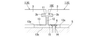
- the upper piece 11 of the fixing member 10A is inserted into the groove 3b on the side surface of the plate-like module 1 having the groove 3b formed on the side surface, and the upper piece 11 is brought into contact with the upper portion of the groove 3b.
- the upper piece 11 may not be exposed on the upper surface of the plate-like module 1 in addition to being able to achieve the same effect as described above.
- the appearance of the upper surface side of the plate module 1 can be improved.
- the fastening member 6 has a head such as a screw or a bolt and is screwed into the mounting member 5 from the upper side of the lower pieces 13 and 23 through the mounting holes 14 and 24.
- the present invention is not limited to this.
- the male screw portion is inserted into the mounting holes 14 and 24 and screwed into the male screw portion from above the lower pieces 13 and 23. It is good also as a nut to make, and also by this, there can exist an effect similar to the above.
- the portion into which the fastening member 6 of the mounting member 5 to which the fixing members 10 and 20 are attached is screwed.
- the present invention is not limited to this.
- a nut 5a may be used, and the same effect as described above may be obtained. Can play.
- the fastening member 6 is screwed into the nut 5a of the mounting member 5, the nut 5a can be slid in a direction perpendicular to the shaft portions 12 and 22 (left and right in FIG. 3A). This makes it possible to adjust the mounting positions of the fixing members 10 and 20 and improve the workability related to the installation of the plate module 1.
Landscapes
- Engineering & Computer Science (AREA)
- General Engineering & Computer Science (AREA)
- Mechanical Engineering (AREA)
- Sustainable Development (AREA)
- Sustainable Energy (AREA)
- Thermal Sciences (AREA)
- Chemical & Material Sciences (AREA)
- Combustion & Propulsion (AREA)
- Physics & Mathematics (AREA)
- Life Sciences & Earth Sciences (AREA)
- Architecture (AREA)
- Civil Engineering (AREA)
- Structural Engineering (AREA)
- Roof Covering Using Slabs Or Stiff Sheets (AREA)
Abstract
太陽電池モジュール等の板状モジュールを確実に固定することができると共に汎用性の高い固定部材を提供する。 固定部材10に、板状モジュール1の上面に当接可能とされ左右方向へ延びた上片11と、上片11の中央から下方へ延出した軸部12と、軸部12の下端から両側へ上片11よりも大きく延び上側に板状モジュール1の下面に当接可能な当接部13a及び湾曲する底面13bを有した下片13と、下片13における軸部12を挟んだ何れか一方側に形成され上下方向へ貫通した取付孔14と、を具備させた上で、固定部材10の軸部12に板状モジュール1の側面を略当接させた状態で、取付孔14を介して下片13を取付部材5に取付けると、上片11が下降して板状モジュール1の上面に当接すると共に、下片13の当接部13aが板状モジュール1の下面に当接するように形成した。
Description
本発明は、屋根上等に設置される太陽熱温水器や太陽電池モジュール等の板状モジュールを屋根上等に固定するための固定部材に関するものである。
従来より、例えば、板状モジュールとしての太陽電池モジュールを、屋根上に設置固定するための固定部材としては、特許文献1に示すような、太陽電池モジュールにおける枠体の側面に形成された凹状の接合部内に挿入される被接合部と、被接合部の中央から垂下する軸部と、軸部の下端に接続され上面に太陽電池モジュールの枠体が載置される台座部と、を備えた固定部材が提案されている。
この固定部材によると、屋地板や屋根材等の取付部材に固定部材を取付けた状態で、固定部材の台座部及び被接合部に太陽電池モジュールの一端側の枠体を支持させ、太陽電池モジュールの他端側の枠体に別の固定部材を取付けた上で、その固定部材を取付部材へ取付けることで、太陽電池モジュールを屋根上等に固定することができる。従って、複数の太陽電池モジュールを一方側(軒側)から他方側(棟側)へ順次固定することができ、太陽電池モジュールの設置に係るコストを低減させることができる。
また、特許文献1のものでは、軸部を挟んで固定部材を取付部材へ取付ける部位とは反対側に爪状の被係合部を備えると共に、太陽電池モジュールの枠体に被係合部と係合する係合部を備えており、被係合部を係合部に係合させることで、軸部から遠ざかる方向へ枠体が移動するのを規制することができるようになっている。これにより、太陽電池モジュールを傾斜した屋根上等に設置した時に、太陽電池モジュールの棟側(上側)を支持する固定部材でも、軒側に配置された太陽電池モジュールが軒側(下側)へ移動するのを阻止することができるので、太陽電池モジュールの荷重を軒側と棟側の固定部材で夫々支持することができるようになっている。
しかしながら、特許文献1のような従来の固定部材では、太陽電池モジュールの枠体が固定部材の台座部と被接合部との間に挿入されているだけなので、それらの寸法公差によっては太陽電池モジュールがガタ付いたり、太陽電池モジュールが固定部材の延びた方向へスライドしてしまったりする虞があった。
また、特許文献1の固定部材では、爪状の被係合部を太陽電池モジュールの枠体に備えられた係合部と係合させるようにしているので、係合部を備えていない太陽電池モジュールでは、棟側の固定部材によって軒側の太陽電池モジュールの荷重を支持することができない問題があると共に、太陽電池モジュールを傾斜した屋根上等に設置する場合では、係合部を備えた太陽電池モジュールを用いる必要があり、汎用性の低いものとなっていた。
そこで、本発明は上記の実情に鑑み、太陽電池モジュール等の板状モジュールを確実に固定することができると共に汎用性の高い固定部材の提供を課題とするものである。
上記の課題を解決するために、本発明に係る固定部材は、「板状モジュールの上面に当接可能、又は、板状モジュールの側面に形成された溝内に挿入可能とされ、左右方向へ延びた上片と、該上片の中央から下方へ延出した軸部と、該軸部の下端から両側へ前記上片よりも大きく延び、上側に板状モジュールの下面に当接可能な当接部を有した下片と、該下片における前記軸部を挟んだ何れか一方側に形成され上下方向へ貫通した取付孔とを少なくとも具備した固定部材であって、該固定部材を、前記軸部に板状モジュールの側面を当接又は接近させた状態で、前記取付孔を介して前記下片を取付部材に取付けると、前記上片が下降して板状モジュールの上面又は溝の上部に当接すると共に、前記下片の前記当接部が板状モジュールの下面に当接するように形成した」ことを特徴とする。
ここで、「板状モジュール」としては、「板状の太陽電池パネルの外周を枠体で囲った太陽電池モジュール」、「太陽熱温水器パネル」、「太陽熱集熱パネル」、「防音パネル」、「遮光パネル」、等を例示することができる。
また、「下片」としては、「軸部から遠ざかるほど上下方向の厚さを厚くし、軸部から遠ざかった先端側の上部を当接部としたもの」、「軸部から遠ざかった先端側に上方へ突出した突出部を形成し、突出部を当接部としたもの」、等を例示することができる。
更に、「取付部材」としては、「屋根の表面を形成する屋根材」、「屋根材が取付けられる屋地板」、「屋根を形成するための垂木等の屋根構造部材」、「板状モジュールを設置する対象物に取付けられた長尺状の桟部材」、「板状モジュールを設置する対象物に取付けられた架台」、「板状モジュールを設置する対象物との間に介装された取付金具」、「壁面」、「壁面を構成するための胴縁」、等を例示することができる。
また、「取付孔を介して下片を取付部材に取付ける」とは、「下片の上側からボルトやビス等を取付孔に挿通し、ボルト等の頭により下片を取付部材側へ押え付けて取付ける」、「取付部材側から突出した雄ネジ部を、下片の下側から取付孔に挿通させ、下片の上側から雄ネジ部に螺合したナットにより下片を取付部材側へ押え付けて取付ける」、等を例示することができる。
更に、「板状モジュールの側面」とは、板状モジュールの一般的な側面や、一般的な側面から突出した端面を含むものである。また、「板状モジュールの側面を接近させた状態」とは、板状モジュールの側面を、上片の先端と軸部との間の中央よりも軸部寄りに位置させた状態であり、望ましくは、上片の先端と軸部との間の距離の1/4よりも軸部寄りに位置させた状態である。これにより、上片と下片の当接部とで板状モジュールを充分に挟持固定することができる。
また、「下片を取付部材に取付けると、上片が下降」とは、「下片の底面を湾曲又は屈曲させることで、軸部の直下が取付部材の上面から浮いた状態とし、下片を取付部材に取付けることで下片を変形させて、上片を下降させるもの」、「下片における軸部を挟んで取付孔とは反対側の先端のみが取付部材に当接するようにし、下片の底面が全体的に取付部材と沿うように取付けることで、上片を下降させるもの」、「下片の底面の両端付近に下方へ突出した突起を備えることで軸部の直下が取付部材の上面から浮いた状態とし、下片を取付部材に取付けることで下片を変形させて、上片を下降させるもの」、等を例示することができる。
これにより、固定部材における軸部を挟んで取付孔とは反対側の上片と下片との間に板状モジュールを挿入すると共に、板状モジュールの側面を軸部に当接又は接近させた状態で、固定部材を屋根材等の取付部材に載置し、下片に形成された取付孔を介してビスやボルト、ナット等により下片を取付部材に取付けると、軸部と共に上片が下降して上片と下片の当接部とで板状モジュールを上下方向に挟んで固定することができるので、板状モジュールがガタ付いたり、固定部材の延びる方向へスライドしてしまったりするのを防止することができ、板状モジュールを確実に固定することができる。
また、上片よりも下片が大きく延び出しているので、固定部材を取付部材へ取付けた状態で、軸部を挟んで取付孔側の上片と下片との間に板状モジュールを斜めにしながら挿入して押し込むことで、軸部を挟んで取付孔側でも板状モジュールを挟んで固定することができる。従って、この固定部材によると、軸部を挟んで両側に板状モジュールを固定することができるので、複数の板状モジュールを一方側から他方側へ順次固定することができ、板状モジュールの設置に係る手間を簡略化することができると共に、設置に係るコストを低減させることができる。
更に、上述したように、固定部材の上片と下片の当接部とで板状モジュールを挟んで固定することができるので、板状モジュールを傾斜させた状態で設置する場合でも、板状モジュールの上下両側を夫々固定した固定部材によって、板状モジュールの荷重を支持することができ、一方の固定部材のみに荷重が偏るのを抑制して偏荷重により固定部材が変形したり破損したりするのを防止することができる。
また、固定部材の上片と下片の当接部とで板状モジュールを挟んで固定するようにしているので、特許文献1に記載された太陽電池モジュールの枠体のように固定部材と係合するための係合部を備えていなくても、挟める形態の板状モジュールであれば固定部材によって確実に固定することができ、汎用性の高い固定部材とすることができると共に、特別な板状モジュールを用いる必要がなく、一般的な(市販の)板状モジュールを用いることができ、板状モジュールによるシステム全体に係るコストを低減させることができる。
ところで、特許文献1では、太陽電池モジュールの枠体における係合部と、固定部材における爪状の被係合部とを、互いに係合させることで、太陽電池モジュールの枠体が軸部から離れる方向(軒側の方向)へ移動するのを規制するようにしている。この場合、太陽電池モジュールの重量によっては係合を強くする必要があり、係合を強くすることで、枠体の側面に対して直角方向から固定部材を挿入嵌合させ難くなり、作業性が悪くなる虞がある。しかしながら、本発明の固定部材によると、特許文献1のもののような爪状の被係合部を備えていないので、板状モジュールの側面に対して直角方向から固定部材を簡単に挿入嵌合させることができ、作業性を良くすることができる。
なお、固定部材は、取付孔を、軸部に対して可及的に近い位置に形成することが望ましく、これにより、取付孔を介して(通して)ビスやボルト、ナット等により下片を取付部材に取付けた時の上片による板状モジュールの固定強度を高くすることができ、板状モジュールをより確実に固定することができる。また、下片の上面に、取付孔を介して固定部材を取付部材に取付けるためのビスやボルト等の頭部、ナット等を収容可能な凹部を形成するようしても良く、これにより、ボルト等の頭部が板状モジュールと当接するのを回避させることができるので、取付孔を可及的に軸部に近付けることができる。
本発明に係る固定部材は、上記の構成に加えて、「取付部材に取付ける前の状態では、前記下片の底面が、前記軸部の直下が最も高くなるように湾曲又は屈曲し、取付部材に取付けることで前記底面が取付部材に沿った状態に変形する」構成としても良い。
これにより、固定部材における下片の底面を、軸部の直下が最も高くなるように湾曲又は屈曲させており、固定部材を取付部材上に置いた状態(取付ける前の状態)では、軸部の直下に隙間が形成された状態となる。その状態で取付孔を介して取付部材に取付けることで、下片が変形して底面が取付部材に沿った状態となり軸部の直下の隙間がなくなるので、隙間の分だけ軸部を介して上片が降下することとなり、下片を取付部材に取付けると上片が降下する固定部材を確実に具現化することができ、上述した作用効果を奏する固定部材とすることができる。
なお、下片を、軸部から遠ざかるほど上下方向の厚さを厚くするようにし、厚くなった先端を当接部とするようにしても良く、これにより、取付部材に取付けることで、下片の中央(軸部の位置)が下がり、相対的に下片の先端(当接部)が上がるので、上片と当接部とで板状モジュールをより強く挟むことができ、板状モジュールを確実に固定することができる。
本発明に係る固定部材は、上記の構成に加えて、「前記下片の前記軸部を挟んで両側に形成され上下方向へ貫通した貫通孔と、該貫通孔へ下側から挿入され、前記取付孔を介して前記下片を取付部材に取付けると、上端が板状モジュールの下面に突き刺さる突刺部を有した補助固定部とを更に具備する」構成としても良い。
ここで、「補助固定部」としては、「軸部を挟んで両側に形成された貫通孔に夫々挿入される突刺部が下片の下側で一体的に連結されたもの」、「軸部を挟んで両側に形成された貫通孔に挿入される突刺部が夫々独立しているもの」、「軸部を挟んで両側に形成された貫通孔に夫々挿入される突刺部が下片の下側で一体的に連結されると共に、下片の底面を取付部材から遠ざかる方向へ付勢する弾性部を有したもの」、等を例示することができる。
これにより、固定部材を取付部材へ取付けると、下片の貫通孔に挿入された補助固定部の突刺部が板状モジュールの下面に突き刺さるので、補助固定部によっても板状モジュールがガタ付いたり固定部材の延びた方向へスライドしたりするのを防止することができ、板状モジュールを確実に固定することができる。
なお、補助固定部を、軸部を挟んだ両側の貫通孔に夫々挿入される突刺部を下片の下側で一体的に連結すると共に導電性を有するようにしても良く、これにより、補助固定部を通じて軸部の両側に固定された板状モジュール同士を電気的に接続することができ、板状モジュール同士のアース接続を簡単に行うことができる。また、表面に絶縁性の被膜を有した板状モジュールでも、補助固定部の突刺部が突刺されることで、被膜を破ることができ、太陽電池モジュール等の板状モジュール同士を、確実に電気的に接続してアース接続することができる。
このように、本発明によると、太陽電池モジュール等の板状モジュールを確実に固定することができると共に汎用性の高い固定部材を提供することができる。
本発明の一実施形態である固定部材について、図1乃至図3(A)~(C)に基いて詳細に説明する。
本実施形態の固定部材10は、図1等に示すように、板状の太陽電池パネル2の外周を枠体3で囲った太陽電池モジュール4等の板状モジュール1を、屋根材等の取付部材5上に設置するためのものであり、ビスやボルト等の所定の締結部材6によって取付部材5へ取付けられるようになっている。本例の固定部材10は、板状モジュール1の上面に当接可能とされ、左右方向へ延びた上片11と、上片11の中央から下方へ延出した軸部12と、軸部12の下端から両側へ上片11よりも大きく延びた下片13と、下片13の軸部12を挟んで一方側に形成され上下方向へ貫通した取付孔14と、を備えている。固定部材10は、軸部12を挟んで上片11及び下片13が夫々左右に略均等に延びだしており、長手方向から見ると、上辺の短い略エ字状に形成されている。
また、固定部材10は、下片13における取付孔14の上部に、取付孔14を通して取付部材5にねじ込まれる締結部材6の頭部を収容可能な凹部15を備えている。この固定部材10は、下片13が軸部12から遠ざかるほど上下方向の厚さが厚くなるように形成されており、軸部12から遠ざかった先端上部が板状モジュール1の下面と当接する当接部13aとされている。また、固定部材10は、図3(A)に示すように、取付部材5に取付ける前の状態では、下片13の底面13bが、軸部12の直下が最も高くなるように湾曲した状態となっている。なお、取付部材5へ取付ける前の状態では、下片13の上面が、先端へ向かうほど低くなるようになっており、上片11と下片13との間に板状モジュール1を挿入し易くなっている。
本例の固定部材10は、アルミ合金等の金属を素材とした押出型材とされており、同一断面形状で長尺状に形成したものを適宜長さ(本例では、100mm~200mm)に切断して、取付孔14や凹部15等を長手方向に1つ~3つ形成したものである。因みに、板状モジュール1は、一般市販品とされ、固定部材10により固定される長辺の長さが、900mm~2000mmとされている。
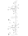
次に、本例の固定部材10を用いた板状モジュール1の固定方法について説明する。まず、例えば、取付部材5上の所定位置に描かれたケガキ線に沿って固定部材10を載置した上で、取付孔14にビスやボルト等の締結部材6を挿入し、固定部材10における下片13の底面13bが取付部材5の上面と一致するまで締結部材6を取付部材5へねじ込む。そして、取付けた固定部材10の上片11と下片13との間に板状モジュール1の一方の側面を挿入した上で、板状モジュール1の対向する他方の側面に、新たな固定部材10を挿入する。具体的には、固定部材10における軸部12を挟んで取付孔14が形成された一方側とは反対側の上片11と下片14との間に板状モジュール1の他方の側面が位置するように固定部材10を挿入し、固定部材10を取付部材5上に載置する(図3(A)を参照)。
この状態では、固定部材10の底面13bが湾曲した状態となっており、下片13の両端が取付部材5の上面と当接し、底面13bと取付部材5の上面との間で軸部12の直下が最も大きくなるような隙間が形成された状態となっている。そして、固定部材10の上側から締結部材6を取付孔14に挿入した上で、締結部材6を取付部材5へねじ込むことで、締結部材6の頭部が下降して凹部15内へ進入し、頭部が凹部15の底に当接すると、底面13bが湾曲した下片13が締結部材6の頭部によって下方へ押されることとなる。これにより、湾曲した下片13の底面13bが延びる方向へ変形し、締結部材6(頭部)の下降と共に、下片13を介して軸部12及び上片11が下降する。
そして、下片13の底面13bにおける軸部12の直下が取付部材5の上面と当接すると、湾曲した底面13bが取付部材5の上面に沿った形状(ここでは、略直線状)となると共に下片13を介した軸部12及び上片11の下降が停止する。この時、上片11が下降することで板状モジュール1の上面と当接すると共に、下片13における軸部12の直下の中央が下降することで、相対的に下片13の先端の当接部13aが上昇して板状モジュール1の下面と当接し、板状モジュール1が上片11と下片13の当接部13aとで上下方向に挟持された状態となり、板状モジュール1の他方の側面が固定された状態となる(図3(B)を参照)。
続いて、軸部12を挟んで取付孔14とは反対側で一つ目の板状モジュール1を固定した固定部材10に対し、軸部を挟んで取付孔14側の上片11と下片13との間に、別の板状モジュール1における一方の側面を挿入する。この時、図3(B)に示すように、板状モジュール1を取付部材5の上面に対して斜めに傾けた状態で、下片13の上面に沿ってスライドさせるように側面を挿入した上で、板状モジュール1を、その上面が先に固定した板状モジュール1の上面と略同一面状となるように位置させる。これにより、下降した上片11と、下片13との間に板状モジュール1を少ない力で挿入することができる。
そして、板状モジュール1の一方の側面を固定部材10に固定(支持)させたら、板状モジュール1の他方の側面に、新たな固定部材10を挿入し、その固定部材10を上述と同様に取付部材5へ取付けることで、二つ目の板状モジュール1を固定することができ、複数の板状モジュール1を一方側から他方側へ向かって順次固定することができる。
このように、本実施形態の固定部材10によると、下片13に形成された取付孔14を介してビスやボルト等の締結部材6により下片13を取付部材5に取付けると、軸部12と共に上片11が下降して上片11と下片13の当接部13aとで板状モジュール1を上下方向に挟んで固定することができるので、板状モジュール1がガタ付いたり、固定部材10の延びる方向へスライドしてしまったりするのを防止することができ、板状モジュール1を確実に固定することができる。
また、上片11よりも下片13が大きく延び出しており、固定部材10を取付部材5へ取付けた状態で、軸部12を挟んで取付孔14側の上片11と下片13との間に板状モジュール1を斜めにしながら挿入して押し込むことで、軸部12を挟んで取付孔14側でも板状モジュール1を挟んで固定することができるので、軸部12を挟んで両側に板状モジュール1を固定することができ、複数の板状モジュール1を一方側から他方側へ順次固定することで板状モジュール1の設置に係る手間を簡略化することができると共に、設置に係るコストを低減させることができる。
更に、固定部材10の上片11と下片13の当接部13aとで板状モジュール1を挟んで固定することができるので、傾斜した屋根上等、板状モジュール1を傾斜させた状態で設置しても、板状モジュール1の上下両側を夫々固定部材10によって支持することができ、一方(下側)の固定部材10のみに荷重が偏るのを抑制して偏荷重により固定部材10が変形したり破損したりするのを防止することができる。
以上、本発明について好適な実施形態を挙げて説明したが、本発明はこの実施形態に限定されるものではなく、以下に示すように、本発明の要旨を逸脱しない範囲において、種々の改良及び設計の変更が可能である。
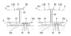
すなわち、上記の実施形態では、固定部材10の下片13が、軸部12から遠ざかるほど上下方向の厚さが厚くなるものを示したが、これに限定するものではなく、例えば、図4(A),(B)に示すような固定部材20としても良い。なお、基本的な構成については上記の実施形態と同一の名称を付し、詳細な説明は省略する。この固定部材20は、上片21及び軸部22が上記の実施形態と同様の形態となっているのに対し、下片23が異なる形態となっている。具体的には、下片23は、軸部22から左右方向へ一定厚さで上片21よりも大きく延びた上で、先端が一旦所定量上方へ延出した上で上端から左右方向外方(軸部22から遠ざかる方向)へ取付部材5の上面と略平行に延びだした形態とされており、その延びだした上面が当接部23aとされている。
なお、下片23における軸部22を挟んで一方側(図4(A)中、右側)で軸部22と当接部23aとの間に上下方向に貫通した取付孔24が形成されていると共に、下片23における当接部23aから軸部22までの上面側の間が当接部23aよりも凹んだ形態となっており、締結部材6の頭部等を収容可能な凹部25とされている。この固定部材20もまた、取付部材5へ取付ける前の状態では、下片23の底面23aが軸部22の直下が最も高くなるように湾曲しており、上記の固定部材10と同様の作用効果を奏することができる。
また、上記の実施形態では、板状モジュール1として、側面が平坦なものに対応した固定部材10,20を示したが、これに限定するものではなく、例えば、図5(A),(B)に示すような、側面から外方へ延出した固定用のフランジ部3aを有した板状モジュール1と対応した固定部材20Aとしても良い。この固定部材20Aは、図5(A),(B)に示すように、図4(A),(B)に示した固定部材20における上片21が、左右両端に下方へ突出し板状モジュール1のフランジ部3aの上面と当接可能な突出部21aを備えた形態とされているものである。この固定部材20Aによると、側面にフランジ部3aを備えた板状モジュール1にも対応することができ、上記と同様の作用効果を奏することができる。また、突出部21aがフランジ部3aの上面に突き刺さるようにしても良く、これにより、軸部22を挟んで両側に配置された板状モジュール1同士を電気的に接続することができる。
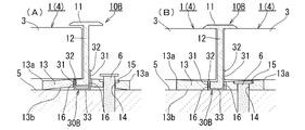
更に、上記の実施形態では、固定部材10,20,20Aの上片11,21と下片13,23の当接部13a,23aとで板状モジュール1を挟むのみのものを示したが、これに限定するものではなく、図6(A),(B)及び図7(A),(B)に示すような板状モジュール1の固定を補助する補助固定部30,30Aを更に備えるようにしても良い。まず、図6(A),(B)に示す固定部材10Aは、上記の固定部材10の構成に加えて、下片13の軸部12を挟んで両側に夫々上下方向へ貫通した貫通孔16を備えていると共に、各貫通孔16へ下側から挿入される挿入片31及び挿入片31の上端に形成され先端が尖った突刺部32を有する補助固定部30を備えている。この例の補助固定部30は、一対の挿入片31の下端同士が連結片33によって連結されており、図6(A)に示すように略コ字状に形成されている。また、この補助固定部30は、ステンレス鋼板等の金属板材を折り曲げたものであり、詳細な図示は省略するが、上端の長手方向両端に上方へ尖った突刺部32が形成されている。
この例によると、固定部材10Aにおける下片13の湾曲した底面13bが取付部材5の上面と略一致するように取付孔14を介した締結部材6をねじ込んで、固定部材10Aを取付部材5に取付けると、貫通孔16に挿入された補助固定部30の突刺部32が相対的に下片13の上面から上方へ突出して板状モジュール1の下面に突き刺さるようになっている(図6(B)を参照)。これにより、上片11と下片13の当接部13aとによる挟持に加えて、補助固定部材30の突刺部32が板状モジュール1の下面に突き刺さることで、補助固定部30によっても板状モジュール1がガタ付いたり、固定部材10Aの延びた方向や軸部12から遠ざかる方向へスライドしたりするのを防止することができ、板状モジュール1を確実に固定することができる。また、補助固定部材30は、導電性を有するステンレス鋼板により形成されているので、軸部12を挟んで両側に固定された板状モジュール1同士を電気的に接続することができ、板状モジュール1同士のアース接続を簡単に行うことができる。
一方、図7(A),(B)に示す固定部材20Bは、上記の図4(A),(B)に示した固定部材20の構成に対して、取付部材5に取付ける前の状態でも下片23の底面23bを平坦な状態とした上で、下片23の軸部22を挟んで両側に夫々上下方向へ貫通した貫通孔26を備えていると共に、各貫通孔16へ下側から挿入される挿入片31と突刺部32を有した補助固定部30Aを備えている。この例の補助固定部30Aは、図7(A)に示すように、軸部22を挟んで取付孔24側の貫通孔26に挿入される挿入片31の下端から、連結片33と同一面状に軸部22から遠ざかる方向へ延びた延長片34と、延長片34の先端から斜め下方へ屈曲された弾性片35とを更に備えている。
この例の固定部材20Bは、図7(A)に示すように、固定部材20Bを取付部材5に取付ける前の状態では、下片23の下側に配置された補助固定部30Aの弾性片35により、下片23の底面23aが、軸部22を挟んで取付孔24(弾性片35)とは反対側の先端が取付部材5の上面に当接するだけで、取付孔24側の先端は取付部材5の上面から浮いた状態となるようになっている。この状態で、軸部22を挟んで取付孔24とは反対側の上片21と下片23との間に板状モジュール1を挿入した上で、取付孔24を介して締結部材6をねじ込むと、屈曲した弾性片35が延長片34と同一面となるように展開すると共に、挿入片31の上端の突刺部32が板状モジュール1の下面に突き刺さることとなり(図7(B)を参照)、上記と同様の作用効果を奏することができる。
更に、図6(A),(B)や図7(A),(B)の実施形態では、補助固定部30,30Aにおける両側の突刺部32が、板状モジュール1の下面に夫々突き刺さるものを示したが、これに限定するものではなく、例えば、図8(A),(B)に示すように、軸部12を挟んで取付孔14側の突刺部32が板状モジュール1の側面に突き刺さるようにしても良い。この固定部材10Bは、図6(A),(B)の固定部材10Aに対して、軸部12を挟んで取付孔14側の貫通孔16が、軸部12の根元の位置に形成されていると共に、補助固定部30Bにおける取付孔14側の貫通孔16に挿入される挿入片31が軸部12に沿って上方へ大きく延びだした上で、その挿入片31の上端から左右方向(図8(A)中右方向)へ尖るように突刺部32が形成されている。
この例の固定部材10Bによると、上記と同様の作用効果を奏する他に、軸部12を挟んで取付孔14側の上片11と下片13との間に板状モジュール1を挿入する際に、下片13の貫通孔16から上方へ突出した挿入片31や突刺部32が邪魔になるのを回避させることができ、板状モジュール1を挿入し易くすることができる。
また、上記の実施形態では、固定部材10,20の上片11,21が板状モジュール1の上面に当接するものを示したが、これに限定するものではなく、例えば、図9に示すように、側面に溝3bが形成された板状モジュール1に対して、その側面の溝3b内に固定部材10Aの上片11を挿入させると共に、上片11を溝3bの上部に当接させて、下片13の当接部13aとの間で挟むようにしても良く、これによっても上記と同様の作用効果を奏することができる他に、上片11が板状モジュール1の上面に露出しないので、板状モジュール1の上面側の見栄えを良くすることができる。
また、上記の実施形態では、締結部材6として、ビスやボルト等の頭部を有し下片13,23の上側から取付孔14,24を介して取付部材5へねじ込むものを示したが、これに限定するものではなく、例えば、取付部材5側から雄ねじ部を突出させた上で、その雄ねじ部を取付孔14,24へ挿通させ、下片13,23の上側から雄ねじ部へ螺合させるナットとしても良く、これによっても上記と同様の作用効果を奏することができる。
更に、図1乃至図6(A),(B)、図8(A),(B)及び図9の実施形態では、固定部材10,20を取付ける取付部材5の締結部材6がねじ込まれる部位がねじ孔又はビス孔のものを示したが、これに限定するものではなく、例えば、図7(A),(B)に示すように、ナット5aとしても良く、上記と同様の作用効果を奏することができる。なお、締結部材6を取付部材5のナット5aへねじ込むようにした場合、ナット5aを軸部12,22に対して直角方向(図3(A)中、左右方向)へスライドできるようにしても良く、これにより、固定部材10,20の取付位置を調整することができ、板状モジュール1の設置に係る作業性を高めることができる。
Claims (4)
- 板状モジュールの上面に当接可能、又は、板状モジュールの側面に形成された溝内に挿入可能とされ、左右方向へ延びた上片と、
該上片の中央から下方へ延出した軸部と、
該軸部の下端から両側へ前記上片よりも大きく延び、上側に板状モジュールの下面に当接可能な当接部を有した下片と、
該下片における前記軸部を挟んだ何れか一方側に形成され上下方向へ貫通した取付孔と
を少なくとも具備した固定部材であって、
該固定部材を、前記軸部に板状モジュールの側面を当接又は接近させた状態で、前記取付孔を介して前記下片を取付部材に取付けると、前記上片が下降して板状モジュールの上面又は溝の上部に当接すると共に、前記下片の前記当接部が板状モジュールの下面に当接するように形成したことを特徴とする固定部材。 - 取付部材に取付ける前の状態では、前記下片の底面が、前記軸部の直下が最も高くなるように湾曲又は屈曲し、取付部材に取付けることで前記底面が取付部材に沿った状態に変形することを特徴とする請求項1に記載の固定部材。
- 前記下片の前記軸部を挟んで両側に形成され上下方向へ貫通した貫通孔と、
該貫通孔へ下側から挿入され、前記取付孔を介して前記下片を取付部材に取付けると、上端が板状モジュールの下面に突き刺さる突刺部を有した補助固定部と
を更に具備することを特徴とする請求項1に記載の固定部材。 - 前記下片の前記軸部を挟んで両側に形成され上下方向へ貫通した貫通孔と、
該貫通孔へ下側から挿入され、前記取付孔を介して前記下片を取付部材に取付けると、上端が板状モジュールの下面に突き刺さる突刺部を有した補助固定部と
を更に具備することを特徴とする請求項2に記載の固定部材。
Priority Applications (2)
| Application Number | Priority Date | Filing Date | Title |
|---|---|---|---|
| US13/806,125 US8950721B2 (en) | 2010-07-06 | 2011-04-11 | Securing member |
| EP11803373.7A EP2592197A4 (en) | 2010-07-06 | 2011-04-11 | Fixing member |
Applications Claiming Priority (2)
| Application Number | Priority Date | Filing Date | Title |
|---|---|---|---|
| JP2010153563A JP5501125B2 (ja) | 2010-07-06 | 2010-07-06 | 固定部材 |
| JP2010-153563 | 2010-07-06 |
Publications (1)
| Publication Number | Publication Date |
|---|---|
| WO2012005037A1 true WO2012005037A1 (ja) | 2012-01-12 |
Family
ID=45441023
Family Applications (1)
| Application Number | Title | Priority Date | Filing Date |
|---|---|---|---|
| PCT/JP2011/058998 Ceased WO2012005037A1 (ja) | 2010-07-06 | 2011-04-11 | 固定部材 |
Country Status (4)
| Country | Link |
|---|---|
| US (1) | US8950721B2 (ja) |
| EP (1) | EP2592197A4 (ja) |
| JP (1) | JP5501125B2 (ja) |
| WO (1) | WO2012005037A1 (ja) |
Cited By (1)
| Publication number | Priority date | Publication date | Assignee | Title |
|---|---|---|---|---|
| JP2017011953A (ja) * | 2015-06-25 | 2017-01-12 | ソーラーフロンティア株式会社 | フレーム及びそれを備える太陽電池モジュール |
Families Citing this family (17)
| Publication number | Priority date | Publication date | Assignee | Title |
|---|---|---|---|---|
| US9518596B2 (en) * | 2009-07-02 | 2016-12-13 | Solarcity Corporation | Pivot-fit frame, system and method for photovoltaic modules |
| US11022343B2 (en) * | 2011-09-02 | 2021-06-01 | Pv Solutions, Llc | Mounting system for photovoltaic arrays |
| JP5963463B2 (ja) * | 2012-02-02 | 2016-08-03 | シャープ株式会社 | 太陽電池モジュールの設置構造、太陽電池モジュールの設置方法、太陽電池モジュール設置用桟、及び太陽光発電システム |
| JP6147047B2 (ja) * | 2013-03-27 | 2017-06-14 | 積水ハウス株式会社 | 集熱パネルおよび太陽熱集熱器 |
| CN103219406B (zh) * | 2013-04-01 | 2015-12-23 | 友达光电股份有限公司 | 太阳能模块的支架与应用其的太阳能系统 |
| JP6280712B2 (ja) * | 2013-09-09 | 2018-02-14 | 元旦ビューティ工業株式会社 | 接地用導電部材、及びそれを用いた太陽電池モジュールの接地構造 |
| JP6129059B2 (ja) * | 2013-11-25 | 2017-05-17 | 三菱電機株式会社 | 太陽電池モジュール取付け構造 |
| JP6207416B2 (ja) * | 2014-02-03 | 2017-10-04 | 三菱電機株式会社 | 固定金具およびそれを備える太陽電池システム |
| JP6283239B2 (ja) * | 2014-03-11 | 2018-02-21 | 積水化学工業株式会社 | 太陽エネルギー収集パネルの固定構造及び方法 |
| US10256767B1 (en) * | 2014-10-03 | 2019-04-09 | Orion Solar Racking, Inc. | System and method for mounting PV panels in bracket and/or rail mount design |
| DE102015202596B3 (de) * | 2015-02-12 | 2016-06-16 | Solibro Hi-Tech Gmbh | Klemmvorrichtung und Verfahren zur Montage eines Solarmoduls |
| JP6633865B2 (ja) * | 2015-08-07 | 2020-01-22 | トヨタホーム株式会社 | 太陽電池モジュール固定部材、太陽光発電システム、太陽電池モジュール固定構造、及び太陽電池モジュール固定方法 |
| GB2541927A (en) | 2015-09-04 | 2017-03-08 | Viridian Concepts Ltd | Photovoltaic roof covering |
| WO2017126630A1 (ja) * | 2016-01-19 | 2017-07-27 | ソーラーフロンティア株式会社 | 太陽電池モジュールの固定具 |
| JP6440644B2 (ja) * | 2016-02-17 | 2018-12-19 | 株式会社屋根技術研究所 | 太陽電池モジュールの固定部材、太陽電池モジュールの固定構造、及び太陽電池モジュールの固定方法 |
| JP6550011B2 (ja) * | 2016-04-26 | 2019-07-24 | トヨタホーム株式会社 | 太陽電池モジュール固定構造 |
| US10390613B2 (en) * | 2016-04-27 | 2019-08-27 | Norik Kagramanyan | Securement apparatus and methods of using same |
Citations (7)
| Publication number | Priority date | Publication date | Assignee | Title |
|---|---|---|---|---|
| JPH11141096A (ja) * | 1997-11-05 | 1999-05-25 | Matsushita Electric Ind Co Ltd | パネル設置用桟材及びそれを用いたパネル装置 |
| JPH11240397A (ja) * | 1998-02-24 | 1999-09-07 | Honda Access Corp | 車両用太陽電池の取付部材 |
| JP2002252364A (ja) * | 2001-02-26 | 2002-09-06 | Canon Inc | 太陽電池モジュールアレイ及び太陽電池モジュールの設置方法 |
| JP2007165499A (ja) | 2005-12-13 | 2007-06-28 | Yane Gijutsu Kenkyusho:Kk | 太陽電池モジュール枠体 |
| JP2007262764A (ja) * | 2006-03-29 | 2007-10-11 | Yane Gijutsu Kenkyusho:Kk | 太陽電池モジュールのアース取付構造及びアース固定金具 |
| JP2009167793A (ja) * | 2009-05-01 | 2009-07-30 | Yane Gijutsu Kenkyusho:Kk | 太陽電池モジュールの施工方法 |
| JP2011080199A (ja) * | 2009-10-03 | 2011-04-21 | Kaname:Kk | 固定部材 |
Family Cites Families (18)
| Publication number | Priority date | Publication date | Assignee | Title |
|---|---|---|---|---|
| US5076035A (en) * | 1990-09-26 | 1991-12-31 | Wright John T | Channel assembly for mounting building panels |
| JPH07202242A (ja) * | 1993-11-26 | 1995-08-04 | Sanyo Electric Co Ltd | 太陽電池モジュール及び太陽電池装置 |
| US5707136A (en) * | 1996-02-26 | 1998-01-13 | Byers; Thomas L. | Multiple light systems |
| US6105317A (en) * | 1997-09-24 | 2000-08-22 | Matsushita Electric Works, Ltd. | Mounting system for installing an array of solar battery modules of a panel-like configuration on a roof |
| JP2002262364A (ja) * | 2001-03-01 | 2002-09-13 | Kaijo Corp | 観測データ収集システム。 |
| US6460820B1 (en) * | 2001-11-05 | 2002-10-08 | John Gordon Kopp | Combination appliance hold-down plate |
| JP3869292B2 (ja) * | 2002-03-26 | 2007-01-17 | 株式会社Msk | 太陽電池パネル取付用の支持金具 |
| JP3455210B1 (ja) * | 2002-06-07 | 2003-10-14 | 株式会社栄信 | 太陽電池パネル取付け架台及びその組付け方法 |
| ES1059088Y (es) * | 2004-12-22 | 2005-06-16 | Calderon Antonio Moreno | Dispositivo regulable para la fijacion de placas solares. |
| US20080244881A1 (en) * | 2007-04-04 | 2008-10-09 | Zante Anthony A | Flexible height-adjustable c-clip forclamping solar panels |
| JP4290750B2 (ja) * | 2007-06-11 | 2009-07-08 | 株式会社屋根技術研究所 | 太陽電池モジュールの固定構造、太陽電池モジュール用のフレーム及び固定部材 |
| EP2320476A1 (en) * | 2008-08-29 | 2011-05-11 | Sharp Kabushiki Kaisha | Solar cell module attaching structure, and solar cell device |
| US8341917B2 (en) * | 2009-06-03 | 2013-01-01 | Garland Industries, Inc. | Anchoring system for a roof panel system |
| JP5414783B2 (ja) * | 2009-12-25 | 2014-02-12 | 株式会社屋根技術研究所 | 補助部材 |
| US8181402B2 (en) * | 2010-04-01 | 2012-05-22 | Yanegijutsukenkyujo Co., Ltd. | Building-integrated photovoltaic power unit |
| US8418983B2 (en) * | 2010-07-29 | 2013-04-16 | First Solar, Inc. | Slider clip and photovoltaic structure mounting system |
| US8475185B2 (en) * | 2011-03-24 | 2013-07-02 | Solar Mounting Solutions, LLC | Solar panels grounding clip |
| KR20140085420A (ko) * | 2011-11-01 | 2014-07-07 | 가부시키가이샤 야네기주쓰켄큐조 | 태양전지모듈의 고정구조 |
-
2010
- 2010-07-06 JP JP2010153563A patent/JP5501125B2/ja active Active
-
2011
- 2011-04-11 US US13/806,125 patent/US8950721B2/en active Active
- 2011-04-11 WO PCT/JP2011/058998 patent/WO2012005037A1/ja not_active Ceased
- 2011-04-11 EP EP11803373.7A patent/EP2592197A4/en not_active Withdrawn
Patent Citations (7)
| Publication number | Priority date | Publication date | Assignee | Title |
|---|---|---|---|---|
| JPH11141096A (ja) * | 1997-11-05 | 1999-05-25 | Matsushita Electric Ind Co Ltd | パネル設置用桟材及びそれを用いたパネル装置 |
| JPH11240397A (ja) * | 1998-02-24 | 1999-09-07 | Honda Access Corp | 車両用太陽電池の取付部材 |
| JP2002252364A (ja) * | 2001-02-26 | 2002-09-06 | Canon Inc | 太陽電池モジュールアレイ及び太陽電池モジュールの設置方法 |
| JP2007165499A (ja) | 2005-12-13 | 2007-06-28 | Yane Gijutsu Kenkyusho:Kk | 太陽電池モジュール枠体 |
| JP2007262764A (ja) * | 2006-03-29 | 2007-10-11 | Yane Gijutsu Kenkyusho:Kk | 太陽電池モジュールのアース取付構造及びアース固定金具 |
| JP2009167793A (ja) * | 2009-05-01 | 2009-07-30 | Yane Gijutsu Kenkyusho:Kk | 太陽電池モジュールの施工方法 |
| JP2011080199A (ja) * | 2009-10-03 | 2011-04-21 | Kaname:Kk | 固定部材 |
Non-Patent Citations (1)
| Title |
|---|
| See also references of EP2592197A4 |
Cited By (1)
| Publication number | Priority date | Publication date | Assignee | Title |
|---|---|---|---|---|
| JP2017011953A (ja) * | 2015-06-25 | 2017-01-12 | ソーラーフロンティア株式会社 | フレーム及びそれを備える太陽電池モジュール |
Also Published As
| Publication number | Publication date |
|---|---|
| JP5501125B2 (ja) | 2014-05-21 |
| US20130092806A1 (en) | 2013-04-18 |
| EP2592197A4 (en) | 2017-10-04 |
| JP2012017550A (ja) | 2012-01-26 |
| EP2592197A1 (en) | 2013-05-15 |
| US8950721B2 (en) | 2015-02-10 |
Similar Documents
| Publication | Publication Date | Title |
|---|---|---|
| JP5501125B2 (ja) | 固定部材 | |
| JP5611707B2 (ja) | 板状モジュールの固定構造 | |
| JP5611716B2 (ja) | 板状モジュールの固定構造 | |
| JP5705380B2 (ja) | 太陽電池モジュールの固定構造 | |
| CN102282326B (zh) | 太阳电池组件的固定构造、太阳电池组件用的框架及固定构件 | |
| JP3907668B2 (ja) | 太陽電池モジュールの取付け構造 | |
| US8245460B2 (en) | Supporting clasp | |
| JP2010500495A (ja) | Pvモジュール取付及び支持アッセンブリ並びにその取付け方法 | |
| JP3157209U (ja) | 外装パネルの取付装置 | |
| JP4311341B2 (ja) | 機能パネルの取付構造 | |
| JP5178131B2 (ja) | 太陽電池モジュールの取付治具及び取付構造 | |
| JP2018109322A (ja) | 固定装置 | |
| JP6640674B2 (ja) | 横葺屋根における機器搭載用支持装置 | |
| CN117792248B (zh) | 型材安装组件、光伏系统及光伏系统安装方法 | |
| JP2013221323A (ja) | 太陽電池モジュールの取付金具 | |
| JP6045021B2 (ja) | 屋根上設置物の取付具およびその取付具を用いた屋根上設置物の取付方法 | |
| CN220156429U (zh) | 一种檩条安装座及光伏支架 | |
| JP5686771B2 (ja) | 太陽電池モジュールの固定構造、及び太陽電池モジュールの固定方法 | |
| JP3177591U (ja) | 屋根上設置物の取り付け構造 | |
| JP3708937B2 (ja) | 新設屋根取り付け具および新設屋根取り付け方法 | |
| CN221428843U (zh) | 一种光伏边框及光伏组件 | |
| CN222423551U (zh) | 光伏系统 | |
| JP2018031114A (ja) | 屋根上設置物の取付構造 | |
| JP5140655B2 (ja) | 屋根上取付具 | |
| JP2017155468A (ja) | 太陽電池モジュールの固定構造 |
Legal Events
| Date | Code | Title | Description |
|---|---|---|---|
| 121 | Ep: the epo has been informed by wipo that ep was designated in this application |
Ref document number: 11803373 Country of ref document: EP Kind code of ref document: A1 |
|
| WWE | Wipo information: entry into national phase |
Ref document number: 13806125 Country of ref document: US |
|
| NENP | Non-entry into the national phase |
Ref country code: DE |
|
| WWE | Wipo information: entry into national phase |
Ref document number: 2011803373 Country of ref document: EP |