WO2012005100A1 - Dispositif de coussin de sécurité gonflable - Google Patents
Dispositif de coussin de sécurité gonflable Download PDFInfo
- Publication number
- WO2012005100A1 WO2012005100A1 PCT/JP2011/063907 JP2011063907W WO2012005100A1 WO 2012005100 A1 WO2012005100 A1 WO 2012005100A1 JP 2011063907 W JP2011063907 W JP 2011063907W WO 2012005100 A1 WO2012005100 A1 WO 2012005100A1
- Authority
- WO
- WIPO (PCT)
- Prior art keywords
- airbag
- curtain airbag
- adhesive tape
- folded
- mark
- Prior art date
- Legal status (The legal status is an assumption and is not a legal conclusion. Google has not performed a legal analysis and makes no representation as to the accuracy of the status listed.)
- Ceased
Links
Images


Classifications
-
- B—PERFORMING OPERATIONS; TRANSPORTING
- B60—VEHICLES IN GENERAL
- B60R—VEHICLES, VEHICLE FITTINGS, OR VEHICLE PARTS, NOT OTHERWISE PROVIDED FOR
- B60R21/00—Arrangements or fittings on vehicles for protecting or preventing injuries to occupants or pedestrians in case of accidents or other traffic risks
- B60R21/02—Occupant safety arrangements or fittings, e.g. crash pads
- B60R21/16—Inflatable occupant restraints or confinements designed to inflate upon impact or impending impact, e.g. air bags
- B60R21/23—Inflatable members
- B60R21/237—Inflatable members characterised by the way they are folded
-
- B—PERFORMING OPERATIONS; TRANSPORTING
- B60—VEHICLES IN GENERAL
- B60R—VEHICLES, VEHICLE FITTINGS, OR VEHICLE PARTS, NOT OTHERWISE PROVIDED FOR
- B60R21/00—Arrangements or fittings on vehicles for protecting or preventing injuries to occupants or pedestrians in case of accidents or other traffic risks
- B60R21/02—Occupant safety arrangements or fittings, e.g. crash pads
- B60R21/16—Inflatable occupant restraints or confinements designed to inflate upon impact or impending impact, e.g. air bags
- B60R21/20—Arrangements for storing inflatable members in their non-use or deflated condition; Arrangement or mounting of air bag modules or components
- B60R21/201—Packaging straps or envelopes for inflatable members
-
- B—PERFORMING OPERATIONS; TRANSPORTING
- B60—VEHICLES IN GENERAL
- B60R—VEHICLES, VEHICLE FITTINGS, OR VEHICLE PARTS, NOT OTHERWISE PROVIDED FOR
- B60R21/00—Arrangements or fittings on vehicles for protecting or preventing injuries to occupants or pedestrians in case of accidents or other traffic risks
- B60R21/02—Occupant safety arrangements or fittings, e.g. crash pads
- B60R21/16—Inflatable occupant restraints or confinements designed to inflate upon impact or impending impact, e.g. air bags
- B60R21/20—Arrangements for storing inflatable members in their non-use or deflated condition; Arrangement or mounting of air bag modules or components
- B60R21/213—Arrangements for storing inflatable members in their non-use or deflated condition; Arrangement or mounting of air bag modules or components in vehicle roof frames or pillars
Definitions
- the present invention relates to an airbag that is inflated by gas of an inflator that operates in the event of a vehicle emergency, and more particularly to a technique for suppressing twisting of the airbag when the airbag is attached to a vehicle.
- Patent Document 1 Conventionally, as an airbag of a side airbag device, there is one disclosed in Patent Document 1.
- Patent Document 1 discloses a configuration in which twist identifying means is disposed around a folded airbag.
- twist identifying means a configuration is disclosed in which a folding prevention tape material is marked with a pen or the like.
- Patent Document 1 requires a separate work for marking the tape material for preventing the collapse, resulting in complicated work.
- an object of the present invention is to make it possible to attach a mark for twist identification with as simple an operation as possible.
- an airbag apparatus includes an inflator capable of supplying gas, an airbag that is folded into a long shape and that can be inflated and deployed by gas supply from the inflator, and a part thereof Is provided with a long holding body wound around the airbag so as to extend outward from the outer periphery of the airbag.
- the second aspect is the airbag device according to the first aspect, wherein the elongated holding body is an adhesive tape wound around the airbag.
- a 3rd aspect is an airbag apparatus which concerns on a 2nd aspect, Comprising: Adhesive layers of the said adhesive tape are joined, A part of the said elongate holding body is outside from the outer periphery of the said airbag. It is extended towards.
- a fourth aspect is the airbag apparatus according to the third aspect, wherein the adhesive layers at both ends of the adhesive tape are joined together so that a part of the elongated holding body is outside the airbag. It extends outward from the surroundings.
- a fifth aspect is the airbag device according to any one of the first to fourth aspects, wherein the airbag is folded into a long shape in a state where the airbag is finally folded in two, The elongate holding body extends outwardly at a joint where the airbag is finally folded in half.
- a mark for twist identification can be attached with a simple operation.
- the elongated holding body is an adhesive tape wound around the airbag, it is possible to impart a twist identifying mark while winding the airbag relatively easily. In addition, it is difficult to slip after winding.
- a mark for twist identification can be attached with a simple operation.
- a mark for twist identification can be attached with a simple operation. Further, when the airbag is inflated, the joint portion between the adhesive layers at the end of the adhesive tape can be separated relatively easily.
- the airbag when the elongate holding body is wound around the airbag with a part extending outward from the outer periphery of the airbag, the airbag is folded at the seam of the folded shape. Since both side edges can be brought together, it is easy to maintain the folded form of the airbag.
- the curtain airbag is first aligned when the curtain airbag is inflated and deployed. Since it expand
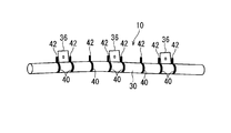
- FIG. 1 is a schematic diagram showing the overall configuration of the curtain airbag device 10.
- the curtain airbag device 10 is provided in a side part of the vehicle interior and is configured to be deployable along a side surface of the vehicle interior in the event of a vehicle emergency, and includes an inflator 22 and a curtain airbag 30. .
- the inflator 22 is formed in a rod shape and supplies high-temperature and high-pressure gas into the curtain airbag 30 according to a detection signal at the time of a vehicle collision.
- the curtain airbag 30 is formed in a bag shape that can be inflated and deployed in a flat shape between the side window 16 of the vehicle and the head of an occupant in the vehicle by sewing a base fabric or the like.
- An opening penetrating the inside and outside of the curtain airbag 30 is formed at one end of the curtain airbag 30 (here, the vehicle rear portion with the curtain airbag 30 attached to the vehicle).
- One end of the inflator 22 on the gas supply side is inserted into the curtain airbag 30 through the opening of the curtain airbag 30.
- the curtain airbag 30 is folded in a long shape in a normal state.
- the curtain airbag 30 is folded by, for example, roll folding, bellows folding, or a combination of these.
- the curtain airbag 30 is provided with an attachment piece 36 for attaching the curtain airbag device 10 to the vehicle.
- the attachment piece 36 is formed, for example, by partially extending a base fabric constituting the curtain airbag 30 outward.
- the attachment piece 36 is attached and fixed to the vehicle via an attachment bracket B (see FIGS. 5 and 6) formed by appropriately punching and pressing a metal plate or the like. That is, the attachment piece 36 is attached to the attachment bracket B via an attachment structure such as a sandwiching structure between the screw head or nut and the attachment bracket B. Then, the mounting bracket B is attached to the vehicle via a fixing structure such as a hooking structure or a screwing structure, so that the curtain airbag 30 folded in a long shape has a roof above the side window 16. Attached along the side rail 12.
- the curtain airbag 30 is covered with a vehicle interior panel or the like so that it cannot be seen from the vehicle interior.
- the gas supplied from the inflator 22 is introduced into the curtain airbag 30.
- the curtain airbag 30 inflated thereby opens the space between the interior panel and the roof side rail 12 and expands toward the vehicle interior, and is flat between the vehicle side window 16 and the head of the vehicle occupant. Inflated and deployed in a bag shape (see curtain airbag 30 shown by a two-dot chain line in FIG. 1).
- the curtain airbag device 10 includes an adhesive tape 40 as a long holding body wound around a curtain airbag 30 folded in a long shape.
- FIG. 2 is an explanatory view showing a state in which the adhesive tape 40 is wound around the curtain airbag device 10.
- the adhesive tape 40 is obtained by forming an adhesive layer 40a on one main surface of a flexible belt-like sheet member.
- acetate fiber or the like can be used, and as the adhesive layer 40a, an adhesive (including an adhesive) that can be bonded to the counterpart member by applying pressure can be used.
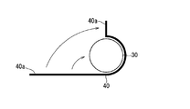
- the adhesive tape 40 is wound around, for example, a curtain airbag 30 folded in a long shape as follows. That is, as shown in FIG. 3, the adhesive tape 40 is wound around the curtain airbag 30 such that the surface of the adhesive tape 40 on the side of the adhesive layer 40 a is in contact with the surface of the curtain airbag 30. At this time, one end of the adhesive tape 40 is extended outward (upward in FIG. 3) from a predetermined position (upper position in FIG. 3) around the outer periphery of the curtain airbag 30. The extension position of one end of the adhesive tape 40 may be positioned with reference to the mounting piece 36 or the folded shape of the curtain airbag 30 as will be described later. And as shown in FIG.
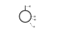
- the adhesive layer 40a of the other end part of the adhesive tape 40 wound around the curtain airbag 30 and the adhesive layer 40a of the one end part of the adhesive tape 40 are abutted and joined. Thereby, both ends which are a part of adhesive tape 40 are extended outward from the predetermined position (here upper position) of the outer periphery of curtain airbag 30 folded in a long shape.
- the outwardly extending portion 42 protrudes radially outward in the cross-sectional shape of the curtain airbag 30 folded in a long shape, and constitutes a twist identifying mark 42.
- the adhesive layer 40a at one end of the adhesive tape 40 and the adhesive layer at the other end need not completely overlap, and the end adhesive layer 40a may be exposed to the outside.
- the adhesive tape 40 When the adhesive tape 40 is wound around the curtain airbag 30, the adhesive tape 40 may be cut into a predetermined length in advance, or the adhesive tape 40 is wound around a winding core.
- the winding operation may be performed in a state where the winding operation is performed, and after the winding operation, the portion of the adhesive tape 40 that has been wound may be separated from the portion wound around the core.
- the belt-like sheet member that is the base material of the adhesive tape 40 preferably has a configuration that can be easily cut in the width direction from the viewpoint of workability.
- the belt-like sheet member is constituted by a cloth-like sheet such as acetate fiber
- the strength of the warp yarn along the longitudinal direction of the belt-like sheet member is smaller than the strength of the weft yarn along the width direction of the belt-like sheet member. It is preferable to do.
- the adhesive tape 40 is attached to a plurality of locations in the longitudinal direction of the curtain airbag 30 folded in a long shape.
- the position where the adhesive tape 40 is provided on the folded curtain airbag 30 preferably includes the side position of the mounting piece 36 (that is, the side position of the mounting portion on the vehicle).
- the curtain airbag 30 can be maintained in a compact and well-folded form at the side position of the attachment piece 36.
- the curtain airbag 30 is less likely to interfere with the attachment piece 36 and its peripheral portion, and the curtain airbag device 10 is smoothly attached to the vehicle. Because it can.
- the adhesive tape 40 is provided in at least one place between the adjacent mounting pieces 36, and the mark 42 is provided on the adhesive tape 40. This is because the presence or absence of twist of the curtain airbag 30 can be confirmed between the adjacent mounting pieces 36.
- all of the adhesive tape 40 wound around the curtain airbag 30 has the mark 42. It is preferable that the extending position of the mark 42 with respect to the outer periphery of the folded curtain airbag 30 is uniform in all the adhesive tapes 40. For example, all the marks 42 may be aligned so as to extend above the folded curtain airbag 30.
- the adhesive tape 40 is provided at both side positions of each attachment piece 36 and at least one position between the adjacent attachment pieces 36, and the marks 42 are provided on all the adhesive tapes 40. Is preferred.
- a preferable aspect of the extending position of the mark 42 will be described in relation to the folded form of the curtain airbag 30.
- the curtain airbag 30 is folded into a flat roll shape, it is finally folded in two from the flat shape and folded into a long shape as shown in FIG. And
- the curtain airbag 30 folded into a flat roll shape in the horizontal direction is folded in two so that the center line in the width direction of the upper surface thereof is a valley line, and both side edges are abutted upward. ing.
- the seam 38 is formed in the upper part of the curtain airbag 30 folded in a long shape.
- 5 and 6 are explanatory views of a cross-sectional portion of the curtain airbag 30 where the attachment piece 36 is provided.
- the curtain airbag 30 may be folded in a bellows shape.
- the curtain airbag 30 is bonded at a seam 38 in the final folded state.
- the mark 42 by the tape 40 extends outward. More specifically, the adhesive layers 40a at both ends of the adhesive tape 40 are abutted and joined at the outer position of the joint 38, and the mark 42 resulting from the joint extends on the outward extension of the joint 38. Like that. Thereby, when forming the mark 42, the both-sides edge part of the curtain airbag 30 can be brought together so that the joint line 38 may be plugged, and it is easy to maintain the folding form of the curtain airbag 30 more reliably.
- the curtain airbag device 10 configured in this way is attached to a vehicle, it can be confirmed that the curtain airbag 30 is not twisted using the mark 42 as a clue. That is, when the curtain airbag 30 is not twisted, as shown in FIGS. 1 and 2, the marks 42 of all the adhesive tapes 40 face in the same direction (here, the upward direction). On the other hand, when the curtain airbag 30 is twisted, as shown in FIG. 8, the marks 42 of some of the adhesive tapes 40 face in different directions from the marks 42 of the other adhesive tapes 40. End up. In FIG. 8, the third mark 42 from the right is directed downward, and the front and rear marks thereof are directed obliquely upward. For this reason, the presence or absence of twist of the curtain airbag 30 can be easily confirmed during and after the installation of the curtain airbag device 10.
- a twist identifying mark 42 is formed by extending a part of the adhesive tape 40 outward from the outer periphery of the folded curtain airbag 30. Therefore, the mark 42 can be attached by a simple operation while suppressing an increase in cost. That is, the mark 42 can be easily attached by a partial device when the adhesive tape 40 is wound around the curtain airbag 30.
- the adhesive tape 40 is used as a long holding body that keeps the curtain airbag 30 in a folded form, the mark 42 can be easily formed while the adhesive tape 40 is easily wrapped around the curtain airbag 30. Can do.
- the adhesive tape 40 is wound around the curtain airbag 30, the adhesive tape 40 is not easily displaced from the curtain airbag 30, and the position of the mark 42 is also difficult to be displaced. For this reason, the presence or absence of twist can be confirmed more reliably.
- the mark 42 can be easily formed by bonding the adhesive layers 40a of the adhesive tape 40 together.
- the marks 42 are formed by bonding the adhesive layers 40a at both ends of the adhesive tape 40, the adhesive tape 40 is wound around the curtain airbag 30 and the ends are bonded together. If the operation of maintaining the form is performed, the mark 42 can be formed, and the mark 42 can be easily formed.
- the structure which joined the adhesive layers 40a of the both ends of the adhesive tape 40 compared with the structure which wound the edge part of the adhesive tape 40 around the own back surface (adhesive layer is an inner surface) of the adhesive tape, and processed.
- Adhesive strength is high and it is difficult to peel off. For this reason, the folded form of the curtain airbag 30 can be held more reliably.
- the part which joined the adhesive layers 40a of the both ends of the adhesive tape 40 is easy to be parted easily by the force which spreads to the radial direction outer side of the wound adhesive tape. For this reason, when the curtain airbag 30 is inflated and deployed, both end portions of the adhesive tape 40 can be easily separated.
- a mark 42 formed by extending a part of the adhesive tape 40 outward from the outer periphery of the curtain airbag 30 is located outside the seam 38 in the final two-folded form of the curtain airbag 30. Is formed. For this reason, when the mark 42 is formed, both side edges of the curtain airbag 30 can be brought together at the joint 38. For example, in the above-described embodiment, when the adhesive layers 40 a at both ends of the adhesive tape 40 are abutted and joined together, both side edges of the curtain airbag 30 can be brought together at the joint 38. For this reason, it is easy to keep the folded curtain airbag 30 in a more compact and constant form.
- the curtain airbag 30 when the curtain airbag 30 is inflated and deployed, the curtain airbag 30 is first inflated so as to open the joint 38, so that the joint portions of the adhesive layers 40a at both ends of the adhesive tape 40 are easily separated, The winding state by the adhesive tape 40 is easily released.
- the curtain airbag device 10 that is provided in a side part of the vehicle interior and that is deployed along the side of the vehicle interior in the event of an emergency of the vehicle has been described. It may be. That is, the airbag device is folded in a long shape in a normal state, and any airbag device that expands in a flat shape from the folded shape may be used.
- the mark 42 may be omitted at the end of the curtain airbag 30 or the like.
- the marks 42 are provided on all the adhesive tapes 40.
- all the marks 42 are aligned in the outer periphery of the curtain airbag 30, but this is not essential.
- the position of the mark 42 at the side position of the attachment piece 36 may be different from the position of the mark 42 between the attachment pieces 36.
- the example in which the mark 42 is formed by the adhesive tape 40 is not limited to the above example.
- the middle part in the longitudinal direction of the adhesive tape 40 wound around the curtain airbag 30 is pinched outward, and the adhesive layer 40a at the pinched portion is joined together to form the mark 142 May be.
- the end of the adhesive tape 40 may be wound around the other outer periphery of the adhesive tape 40.
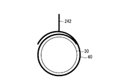
- one end of the adhesive tape 40 wound around the curtain airbag 30 is pinched outward, and the adhesive layer 40a at the pinched portion is joined to mark 242 May be formed. That is, in the above embodiment, the mark 42 is formed by both ends of the adhesive tape 40, but in the present modification, the mark 242 is formed by one end of the adhesive tape 40. In this case, a portion other than the portion where the mark 242 is formed in one end portion of the adhesive tape 40 may be wound around the other outer periphery of the adhesive tape 40.
- the end of the adhesive tape 40 that is to be wound around the curtain airbag 30 is protruded to the outside in the width direction of the adhesive tape 40 to be wound, and the protruding end is twisted for identifying the twist. It is good also as a mark.
- the long holding body wound around the curtain airbag 30 does not necessarily need to be the adhesive tape 40.
- a string or a thread may be used as the long holding body, and the knot may be twisted and used as a mark for identification.
Landscapes
- Engineering & Computer Science (AREA)
- Mechanical Engineering (AREA)
- Air Bags (AREA)
Abstract
On rend aussi facile que possible l'application de marques pour détecter une torsion. L'invention décrit un dispositif de coussin de sécurité gonflable qui est équipé d'un gonfleur capable de fournir un gaz et d'un coussin de sécurité gonflable qui a été plié sous une forme longue et peut être dilaté et déplié par la fourniture de gaz en provenance du gonfleur. Le coussin de sécurité gonflable comporte des supports de forme continue, par ex. des rubans adhésifs qui ont été enroulés autour. Les supports de forme continue dépassent en partie à l'extérieur de la périphérie du coussin de sécurité gonflable pour configurer des marques de détection de torsion.
Priority Applications (2)
| Application Number | Priority Date | Filing Date | Title |
|---|---|---|---|
| EP11803436.2A EP2591953A1 (fr) | 2010-07-05 | 2011-06-17 | Dispositif de coussin de sécurité gonflable |
| US13/805,575 US20130087999A1 (en) | 2010-07-05 | 2011-06-17 | Air bag device |
Applications Claiming Priority (2)
| Application Number | Priority Date | Filing Date | Title |
|---|---|---|---|
| JP2010152791A JP2012011968A (ja) | 2010-07-05 | 2010-07-05 | エアバッグ装置 |
| JP2010-152791 | 2010-07-05 |
Publications (1)
| Publication Number | Publication Date |
|---|---|
| WO2012005100A1 true WO2012005100A1 (fr) | 2012-01-12 |
Family
ID=45441086
Family Applications (1)
| Application Number | Title | Priority Date | Filing Date |
|---|---|---|---|
| PCT/JP2011/063907 Ceased WO2012005100A1 (fr) | 2010-07-05 | 2011-06-17 | Dispositif de coussin de sécurité gonflable |
Country Status (4)
| Country | Link |
|---|---|
| US (1) | US20130087999A1 (fr) |
| EP (1) | EP2591953A1 (fr) |
| JP (1) | JP2012011968A (fr) |
| WO (1) | WO2012005100A1 (fr) |
Cited By (1)
| Publication number | Priority date | Publication date | Assignee | Title |
|---|---|---|---|---|
| US8475686B2 (en) | 2008-12-03 | 2013-07-02 | Novaled Ag | Bridged pyridoquinazoline or phenanthroline compounds and organic semiconducting material comprising that compound |
Families Citing this family (10)
| Publication number | Priority date | Publication date | Assignee | Title |
|---|---|---|---|---|
| JP5314919B2 (ja) * | 2008-04-23 | 2013-10-16 | 芦森工業株式会社 | エアバッグ装置 |
| KR101207394B1 (ko) * | 2010-11-02 | 2012-12-04 | 아우토리브 디벨롭먼트 아베 | 차량용 커튼 에어백의 꼬임방지장치 |
| JP5783818B2 (ja) * | 2011-06-23 | 2015-09-24 | 芦森工業株式会社 | エアバッグ装置 |
| JP5848091B2 (ja) * | 2011-10-26 | 2016-01-27 | 芦森工業株式会社 | サイドエアバッグ装置 |
| JP6107685B2 (ja) * | 2014-01-28 | 2017-04-05 | 豊田合成株式会社 | 頭部保護エアバッグ装置 |
| EP3476666B1 (fr) * | 2015-04-13 | 2020-10-28 | Autoliv Development AB | Dispositif de rideau gonflable pour véhicule |
| KR102083142B1 (ko) * | 2016-09-05 | 2020-03-02 | 현대모비스 주식회사 | 커튼 에어백 장치 |
| JP6836186B2 (ja) * | 2017-08-24 | 2021-02-24 | 豊田合成株式会社 | 頭部保護エアバッグの折り完了体 |
| DE102018009358A1 (de) * | 2018-11-29 | 2020-06-04 | Dalphi Metal Espana, S.A. | Airagmodul und verfahren zu seiner herrstellung |
| DE102022121621A1 (de) | 2022-08-26 | 2024-02-29 | Volkswagen Aktiengesellschaft | Verfahren zum Aufheizen eines Katalysators in der Abgasanlage eines fremdgezündeten Verbrennungsmotors |
Citations (5)
| Publication number | Priority date | Publication date | Assignee | Title |
|---|---|---|---|---|
| JPH11321532A (ja) | 1998-05-12 | 1999-11-24 | Toyoda Gosei Co Ltd | サイドエアバッグ装置のエアバッグ |
| JP2004098707A (ja) * | 2002-09-04 | 2004-04-02 | Honda Motor Co Ltd | 乗員保護装置 |
| JP2004224255A (ja) * | 2003-01-24 | 2004-08-12 | Toyota Motor Corp | エアバッグ装置 |
| JP2006168398A (ja) * | 2004-12-13 | 2006-06-29 | Tkj Kk | エアバッグ装置 |
| JP2009051446A (ja) * | 2007-08-29 | 2009-03-12 | Autoliv Development Ab | カーテンエアバッグ装置 |
Family Cites Families (10)
| Publication number | Priority date | Publication date | Assignee | Title |
|---|---|---|---|---|
| JP3925226B2 (ja) * | 2002-02-12 | 2007-06-06 | タカタ株式会社 | カーテンエアバッグ及びカーテンエアバッグ装置 |
| US20040000775A1 (en) * | 2002-07-01 | 2004-01-01 | David Henderson | Inflatable curtain positioning tabs |
| US7083188B2 (en) * | 2003-11-13 | 2006-08-01 | Autoliv Asp, Inc. | Tearable retention apparatus and method for an airbag cushion |
| US7357408B2 (en) * | 2005-02-28 | 2008-04-15 | Autoliv Asp, Inc. | Inflatable curtain cushion tab shock absorption |
| US7748734B2 (en) * | 2005-10-14 | 2010-07-06 | Tk Holdings Inc. | Twist resistant head side airbag |
| US7641220B2 (en) * | 2007-03-05 | 2010-01-05 | Autoliv Asp, Inc. | Airbag fold bracket |
| US7823914B2 (en) * | 2007-05-14 | 2010-11-02 | Autoliv Asp, Inc. | Airbag mounting assembly and method of manufacture |
| US20090102166A1 (en) * | 2007-10-23 | 2009-04-23 | Tk Holdings Inc. | Airbag module |
| JP5131133B2 (ja) * | 2008-10-03 | 2013-01-30 | 豊田合成株式会社 | 頭部保護エアバッグ |
| US8613466B2 (en) * | 2011-05-10 | 2013-12-24 | Tk Holdings Inc. | Side-impact airbag module |
-
2010
- 2010-07-05 JP JP2010152791A patent/JP2012011968A/ja active Pending
-
2011
- 2011-06-17 EP EP11803436.2A patent/EP2591953A1/fr not_active Withdrawn
- 2011-06-17 US US13/805,575 patent/US20130087999A1/en not_active Abandoned
- 2011-06-17 WO PCT/JP2011/063907 patent/WO2012005100A1/fr not_active Ceased
Patent Citations (5)
| Publication number | Priority date | Publication date | Assignee | Title |
|---|---|---|---|---|
| JPH11321532A (ja) | 1998-05-12 | 1999-11-24 | Toyoda Gosei Co Ltd | サイドエアバッグ装置のエアバッグ |
| JP2004098707A (ja) * | 2002-09-04 | 2004-04-02 | Honda Motor Co Ltd | 乗員保護装置 |
| JP2004224255A (ja) * | 2003-01-24 | 2004-08-12 | Toyota Motor Corp | エアバッグ装置 |
| JP2006168398A (ja) * | 2004-12-13 | 2006-06-29 | Tkj Kk | エアバッグ装置 |
| JP2009051446A (ja) * | 2007-08-29 | 2009-03-12 | Autoliv Development Ab | カーテンエアバッグ装置 |
Cited By (1)
| Publication number | Priority date | Publication date | Assignee | Title |
|---|---|---|---|---|
| US8475686B2 (en) | 2008-12-03 | 2013-07-02 | Novaled Ag | Bridged pyridoquinazoline or phenanthroline compounds and organic semiconducting material comprising that compound |
Also Published As
| Publication number | Publication date |
|---|---|
| US20130087999A1 (en) | 2013-04-11 |
| EP2591953A1 (fr) | 2013-05-15 |
| JP2012011968A (ja) | 2012-01-19 |
Similar Documents
| Publication | Publication Date | Title |
|---|---|---|
| WO2012005100A1 (fr) | Dispositif de coussin de sécurité gonflable | |
| EP3284637B1 (fr) | Airbag rideau | |
| KR102596089B1 (ko) | 루프 에어백 장치 | |
| JP2005519797A5 (fr) | ||
| JP4981915B2 (ja) | 可撓性固定連結具を備えるエアバッグ | |
| US20150123382A1 (en) | Protective flap for airbags | |
| JP2010254057A (ja) | エアバッグ装置 | |
| WO2016170892A1 (fr) | Dispositif de coussin de sécurité gonflable de type rideau | |
| JP2010126078A (ja) | エアバッグ及びエアバッグ装置 | |
| US7516978B2 (en) | Anti-telescoping inflatable curtain | |
| JP2000079864A (ja) | 乗員保護カーテン、その取付構造及び取付方法 | |
| JP6116947B2 (ja) | エアバッグ装置 | |
| JP2009051446A (ja) | カーテンエアバッグ装置 | |
| JP5804528B2 (ja) | カーテンエアバッグ装置 | |
| US8864167B2 (en) | Gas bag arrangement for a vehicle occupant restraint system and method for manufacturing such gas bag arrangement | |
| JP6294622B2 (ja) | カーテンエアバッグ装置の取付構造 | |
| JP5480179B2 (ja) | カーテンエアバッグ装置 | |
| JP4403028B2 (ja) | 頭部保護用エアバッグの車体への取付装置 | |
| WO2016002483A1 (fr) | Dispositif de ceinture de sécurité gonflable | |
| JPWO2020129590A1 (ja) | カーテンエアバッグ及びその製造方法 | |
| JP5214192B2 (ja) | 車両用エアバッグおよびその折り畳み方法 | |
| JP5992855B2 (ja) | カーテンエアバッグ装置及びその取付け構造 | |
| JP6353907B2 (ja) | エアバッグをパッケージ化する方法 | |
| CN223420670U (zh) | 一种气帘装置及车辆 | |
| JP2010234908A (ja) | エアバッグ |
Legal Events
| Date | Code | Title | Description |
|---|---|---|---|
| 121 | Ep: the epo has been informed by wipo that ep was designated in this application |
Ref document number: 11803436 Country of ref document: EP Kind code of ref document: A1 |
|
| WWE | Wipo information: entry into national phase |
Ref document number: 2011803436 Country of ref document: EP |
|
| WWE | Wipo information: entry into national phase |
Ref document number: 13805575 Country of ref document: US |
|
| NENP | Non-entry into the national phase |
Ref country code: DE |