WO2012005228A1 - Dispositif de mesure de flux atomique - Google Patents
Dispositif de mesure de flux atomique Download PDFInfo
- Publication number
- WO2012005228A1 WO2012005228A1 PCT/JP2011/065316 JP2011065316W WO2012005228A1 WO 2012005228 A1 WO2012005228 A1 WO 2012005228A1 JP 2011065316 W JP2011065316 W JP 2011065316W WO 2012005228 A1 WO2012005228 A1 WO 2012005228A1
- Authority
- WO
- WIPO (PCT)
- Prior art keywords
- sheet
- atomic
- flux
- electrode
- current
- Prior art date
- Legal status (The legal status is an assumption and is not a legal conclusion. Google has not performed a legal analysis and makes no representation as to the accuracy of the status listed.)
- Ceased
Links
Images


Classifications
-
- G—PHYSICS
- G01—MEASURING; TESTING
- G01N—INVESTIGATING OR ANALYSING MATERIALS BY DETERMINING THEIR CHEMICAL OR PHYSICAL PROPERTIES
- G01N27/00—Investigating or analysing materials by the use of electric, electrochemical, or magnetic means
- G01N27/62—Investigating or analysing materials by the use of electric, electrochemical, or magnetic means by investigating the ionisation of gases, e.g. aerosols; by investigating electric discharges, e.g. emission of cathode
- G01N27/68—Investigating or analysing materials by the use of electric, electrochemical, or magnetic means by investigating the ionisation of gases, e.g. aerosols; by investigating electric discharges, e.g. emission of cathode using electric discharge to ionise a gas
- G01N27/70—Investigating or analysing materials by the use of electric, electrochemical, or magnetic means by investigating the ionisation of gases, e.g. aerosols; by investigating electric discharges, e.g. emission of cathode using electric discharge to ionise a gas and measuring current or voltage
-
- C—CHEMISTRY; METALLURGY
- C23—COATING METALLIC MATERIAL; COATING MATERIAL WITH METALLIC MATERIAL; CHEMICAL SURFACE TREATMENT; DIFFUSION TREATMENT OF METALLIC MATERIAL; COATING BY VACUUM EVAPORATION, BY SPUTTERING, BY ION IMPLANTATION OR BY CHEMICAL VAPOUR DEPOSITION, IN GENERAL; INHIBITING CORROSION OF METALLIC MATERIAL OR INCRUSTATION IN GENERAL
- C23C—COATING METALLIC MATERIAL; COATING MATERIAL WITH METALLIC MATERIAL; SURFACE TREATMENT OF METALLIC MATERIAL BY DIFFUSION INTO THE SURFACE, BY CHEMICAL CONVERSION OR SUBSTITUTION; COATING BY VACUUM EVAPORATION, BY SPUTTERING, BY ION IMPLANTATION OR BY CHEMICAL VAPOUR DEPOSITION, IN GENERAL
- C23C14/00—Coating by vacuum evaporation, by sputtering or by ion implantation of the coating forming material
- C23C14/22—Coating by vacuum evaporation, by sputtering or by ion implantation of the coating forming material characterised by the process of coating
- C23C14/54—Controlling or regulating the coating process
- C23C14/542—Controlling the film thickness or evaporation rate
- C23C14/543—Controlling the film thickness or evaporation rate using measurement on the vapor source
-
- C—CHEMISTRY; METALLURGY
- C30—CRYSTAL GROWTH
- C30B—SINGLE-CRYSTAL GROWTH; UNIDIRECTIONAL SOLIDIFICATION OF EUTECTIC MATERIAL OR UNIDIRECTIONAL DEMIXING OF EUTECTOID MATERIAL; REFINING BY ZONE-MELTING OF MATERIAL; PRODUCTION OF A HOMOGENEOUS POLYCRYSTALLINE MATERIAL WITH DEFINED STRUCTURE; SINGLE CRYSTALS OR HOMOGENEOUS POLYCRYSTALLINE MATERIAL WITH DEFINED STRUCTURE; AFTER-TREATMENT OF SINGLE CRYSTALS OR A HOMOGENEOUS POLYCRYSTALLINE MATERIAL WITH DEFINED STRUCTURE; APPARATUS THEREFOR
- C30B23/00—Single-crystal growth by condensing evaporated or sublimed materials
- C30B23/002—Controlling or regulating
- C30B23/005—Controlling or regulating flux or flow of depositing species or vapour
-
- G—PHYSICS
- G06—COMPUTING OR CALCULATING; COUNTING
- G06F—ELECTRIC DIGITAL DATA PROCESSING
- G06F17/00—Digital computing or data processing equipment or methods, specially adapted for specific functions
-
- H—ELECTRICITY
- H05—ELECTRIC TECHNIQUES NOT OTHERWISE PROVIDED FOR
- H05H—PLASMA TECHNIQUE; PRODUCTION OF ACCELERATED ELECTRICALLY-CHARGED PARTICLES OR OF NEUTRONS; PRODUCTION OR ACCELERATION OF NEUTRAL MOLECULAR OR ATOMIC BEAMS
- H05H1/00—Generating plasma; Handling plasma
- H05H1/0006—Investigating plasma, e.g. measuring the degree of ionisation or the electron temperature
- H05H1/0081—Investigating plasma, e.g. measuring the degree of ionisation or the electron temperature by electric means
Definitions
- the present invention relates to an atomic flux measuring device for measuring the flux amount of dissociated nitrogen atoms released from a plasma generation cell into a growth chamber.
- sapphire is used as the substrate of the above element, but it has been studied to use a single crystal silicon substrate as a substrate that can be supplied in a large amount at a low cost.
- the silicon substrate has an advantage that it has a higher thermal conductivity than the sapphire substrate and can cope with a high output.
- FIG. 17 is a diagram showing a schematic configuration of an MBE (Molecular Beam Epitaxy) film forming apparatus used when a buffer layer is formed on a silicon substrate.
- MBE Molecular Beam Epitaxy
- the MBE film forming apparatus 1 includes an RF (Radio Frequency) excitation cell 4 and a metal molecular beam cell 5 installed in a vacuum chamber 3 as a storage container, an RF matching box 6 disposed outside the vacuum chamber 3, an RF power source 7 and a personal computer (hereinafter referred to as “PC”) 8.
- the counter electrode body 11 of the atomic flux measuring device 10 is installed near the substrate holder 31 in the vacuum chamber 3, and the main body of the atomic flux measuring device 10 is arranged outside the vacuum chamber 3. It is connected to PC8.
- the inside of the vacuum chamber 3 is maintained at a high vacuum of 10 ⁇ 4 to 10 ⁇ 8 Pa using a turbo vacuum pump (not shown).
- the cleaned silicon substrate 2 is fixed to the substrate holder 31 and heated to a predetermined temperature by a heater (not shown).
- a shroud is provided on the side wall surface of the vacuum chamber 3.
- the inside of the shroud is filled with liquid nitrogen, and gas molecules in the vacuum chamber 3 are adsorbed on the wall surface when colliding with the side wall, and a high degree of vacuum can be maintained.
- FIG. 18 shows a detailed structure of the RE excitation cell 4 for generating nitrogen gas plasma.
- Nitrogen gas supplied from a nitrogen gas cylinder (not shown) through the gas port 45 is supplied into the discharge chamber 42 of the hollow crucible 41. The supply amount of nitrogen gas is adjusted by the flow rate controller 46.
- An excitation coil 43 that also serves as a water cooling pipe is coaxially wound around the outer periphery of the crucible 41, and the cooling water W is circulated to cool the crucible 41 and the RF excitation cell 4.
- the nitrogen gas in the discharge chamber 42 is excited to become a plasma state, and the orifice 44 provided at the outlet portion.
- the nitrogen active species F is released as a supersonic jet.
- the metal molecular beam cell 5 melts a solid metal material such as Ga charged in a crucible with a heater, opens and closes a shutter 9 attached to an outlet portion, and discharges evaporated atoms toward the substrate 2. Although only one metal molecular beam cell 5 is shown in the drawing, a plurality of metal molecular beam cells 5 are usually arranged in the vacuum chamber 3 according to the number of metal molecules to be used.
- the RF matching box 6 is for impedance matching between the RF power source 7 and the plasma in the discharge chamber 42 so that the high frequency power applied to the RF excitation cell 4 from the RF power source 7 is smoothly supplied to the discharge chamber 42.
- the automatic reactance adjustment circuit 61 and the variable reactance circuit 62 are configured.
- the RF excitation cell 4 can be operated in two discharge modes.
- the first discharge mode is called “HB discharge mode”, and a relatively large high frequency power (for example, 500 W) is applied to the excitation coil 43 to excite nitrogen gas in the discharge chamber 42, thereby increasing the high brightness (High Brightness).
- HB discharge mode As shown in the spectrum diagram of FIG. 19, the flux (N + N * ) of the dissociated nitrogen atom in which the ground atom N generated by dissociation of the nitrogen molecule N 2 and the excited atom N * are mixed, as well as the excitation Release of nitrogen molecule N 2 * , nitrogen molecule ion N 2 + and electrons was confirmed.
- the second discharge mode is called “LB discharge mode”, and a relatively small high frequency power (for example, 120 W) is applied to the excitation coil 43 to excite nitrogen gas in the discharge chamber 42, thereby reducing the low brightness (Low Brightness).
- a relatively small high frequency power for example, 120 W
- the plasma emitted from the RF excitation cell 4 does not contain any dissociated nitrogen atom flux (N + N * ), and the emission of excited nitrogen molecules N 2 * , nitrogen molecule ions N 2 + and electrons is confirmed. It was.
- the plasma of the HB discharge mode emitted from the RF excitation cell 4 is reflected on the reflector 32 provided in the vacuum chamber 3 and further on the RF excitation cell 4.
- the energy is consumed by colliding or reflecting at least once with a shutter or shroud and then incident on the surface of the substrate 2.
- indirect irradiation such an irradiation method is referred to as “indirect irradiation”.
- the cleaned silicon substrate 2 is fixed to the substrate holder 31 in the vacuum chamber 3, and the substrate 2 is heated to a predetermined temperature by a heater.
- high frequency power 500 W having a frequency of 13.56 MHz is supplied to the excitation coil 43 of the RF excitation cell 4 to discharge nitrogen gas in the HB discharge mode.
- a dissociated nitrogen atom flux generated in the HB discharge mode is indirectly irradiated onto the substrate, and a ⁇ -Si 3 N 4 single crystal film is epitaxially grown by a surface interface reaction.
- An AlN flux of several atomic layers is irradiated from the Al molecular beam cell on the Si 3 N 4 single crystal film, and the AlN single crystal film is epitaxially grown by surface interface reaction.
- An AlN epitaxial layer is formed by directly irradiating the dissociated nitrogen atom flux and excited nitrogen molecule flux generated by the HB discharge mode on the AlN single crystal film and irradiating the Al atom flux from the Al molecular beam cell. .
- the Langmuir probe method measures the amount of flux of nitrogen atoms.
- the Langmuir probe method measures a current flowing through a metal probe by charged particles.
- Patent Document 2 The inventors have previously developed an apparatus for measuring the flux amount of dissociated nitrogen atoms (see Patent Document 2).
- this measuring device when an electrically neutral dissociated nitrogen atom is attached to a probe electrode having a negative potential, electrons are released from the atom by self-ionization, and a current flows (hereinafter, this current is referred to as “atomic current”). Is used. Since the value of the atomic current flowing through the probe electrode changes according to the amount of atomic flux in the atmosphere in which the probe electrode is placed, the amount of atomic flux can be calculated by measuring the current value.
- the value of the atomic current measured by the atomic flux measuring device varies depending on the amount of atomic flux in the atmosphere where the probe electrode is placed. For this reason, if the probe electrode is installed in the vicinity of the substrate 2, the amount of the atomic flux irradiated to the substrate 2 can be calculated as the value of the atomic current.
- the value of the atomic current output from the probe electrode is small, and it is conceivable to increase the surface area of the probe electrode in order to increase the value of the atomic current.
- the surface area of the electrode is increased, the measuring device becomes larger. It is difficult to secure an installation space in the vacuum chamber.
- the present invention has been made in view of the above problems, and an object of the present invention is to provide an inexpensive and small atomic flux measuring apparatus capable of monitoring the flux amount of dissociated atoms released from a plasma generation cell.
- An atomic flux measuring device is an atomic flux measuring device that measures a flux amount of dissociated atoms released from a plasma generation cell into a container by gas discharge,
- a counter electrode body composed of a first and a second pair of sheet-like electrodes opposed to each other and arranged substantially in parallel at a predetermined interval;
- a first DC power source for applying a DC voltage for causing currents to flow between the first and second sheet-like electrodes by self-ionizing atoms attached to the inside of the first sheet-like electrode;
- a DC ammeter that measures a value of a current flowing by self-ionization of atoms attached to the inside of the first sheet-like electrode between the first and second sheet-like electrodes; To measure atomic flux.
- V B is a potential between the second sheet-like electrode and the ground terminal, and V B is set to a value of 0 or less by the second DC power supply.
- the first sheet-like electrode is preferably made of a metal flat plate, and the first and second sheet-like electrodes or the second sheet-like electrode is preferably made of a metal mesh sheet.
- the counter electrode body may be configured by winding the first and second sheet-like electrodes in a spiral shape with an insulating spacer interposed therebetween.
- the first and second sheet-like electrodes are each composed of a plurality of flat metal mesh sheets having substantially the same shape, and the counter electrode body includes the first and second counter electrode bodies.
- the sheet-like electrodes may be arranged so as to be alternately stacked at a predetermined interval.
- the counter electrode body is provided with a third sheet-like electrode made of a metal mesh sheet on the incident side of the atomic flux, and the potential of the third sheet-like electrode is the same as that of the second sheet-like electrode. It is preferable that it is set.
- one fourth sheet-like electrode is provided at a predetermined interval from the first sheet-like electrode. It is preferable that the fourth sheet-like electrode is connected to the first sheet-like electrode.
- the atomic flux measuring apparatus of the present invention includes an A / D converter that converts the value of the atomic current measured by the DC ammeter into digital data, and a memory that stores the digital data output from the A / D converter. And a display for displaying the digital data stored in the memory, and a control unit for controlling writing and reading of data to and from the memory and a display operation of the display.
- the atomic flux measurement apparatus of the present invention further includes a calculation unit that calculates a flux amount based on the value of the atomic current measured by the DC ammeter, and the calculation unit stores the atomic current stored in the memory in advance.
- a table showing the relationship between the value and the flux amount corresponding to the value of this atomic current is read, and the value of the atomic current measured with the DC ammeter is compared with the value of the atomic current stored in the memory, It is preferable to calculate a flux amount corresponding to the direct current value.
- the atomic flux measuring apparatus of the present invention measures the flux amount of dissociated atoms released from the RF excitation cell based on the value of the atomic current flowing between a pair of sheet-like electrodes, and an appropriate negative bias is applied to one of the electrodes.
- an appropriate negative bias is applied to one of the electrodes.
- the surface area of the electrode can be increased without increasing the volume of the counter electrode body, so the atomic flux is small and has good measurement sensitivity.
- a measuring device can be realized.
- FIG. 1 is a diagram showing a basic configuration of an atomic flux measurement apparatus according to Embodiment 1 of the present invention.
- FIG. 2 is a diagram illustrating an example of a specific configuration of the counter electrode body according to the first embodiment.
- FIG. 3 is a diagram for explaining the principle of the atomic flux monitor.
- FIG. 4 is a graph of voltage-current characteristics created based on the measurement result of the atomic flux measurement device of the first embodiment.
- FIG. 5 is a graph of voltage-current characteristics created based on the measurement result of the atomic flux measurement device of the first embodiment.
- FIG. 6 is a graph of voltage-current characteristics created based on the measurement results of the atomic flux measurement apparatus according to the first embodiment.
- FIG. 4 is a graph of voltage-current characteristics created based on the measurement result of the atomic flux measurement device of the first embodiment.
- FIG. 5 is a graph of voltage-current characteristics created based on the measurement result of the atomic flux measurement device of the first embodiment.
- FIG. 6 is a
- FIG. 7 is a graph of voltage-current characteristics created based on the measurement result of the atomic flux measurement device of the first embodiment.
- FIG. 8 is a graph of voltage-current characteristics created based on the measurement result of the atomic flux measurement device of the first embodiment.
- FIG. 9 is a graph of voltage-current characteristics created based on the measurement result of the atomic flux measurement device of the first embodiment.
- FIG. 10 is a diagram showing a basic configuration of an atomic flux measuring apparatus according to the second embodiment of the present invention.
- FIG. 11 is a diagram illustrating an example of a specific configuration of the counter electrode body according to the second embodiment.
- FIG. 12 is a diagram showing a basic configuration of an atomic flux measurement device according to the third embodiment of the present invention.
- FIG. 13 is a perspective view showing an example of a specific configuration of the counter electrode body in the third exemplary embodiment.
- FIG. 14 is a diagram schematically showing a circuit of the counter electrode body in the third embodiment.
- FIG. 15 is a diagram showing a basic configuration of an atomic flux measurement device according to the fourth embodiment of the present invention.
- FIG. 16 is a diagram schematically showing a circuit of the counter electrode body in the fourth embodiment.
- FIG. 17 is a diagram showing a schematic configuration of the MBE film forming apparatus.
- 18 is a cross-sectional view of the RF excitation cell 4 of FIG.
- FIG. 19 is a diagram showing a spectrum of dissociated nitrogen atom flux emitted from the RF excitation cell 4.
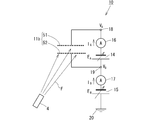
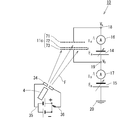
- FIG. 1 shows a basic configuration of an atomic flux measuring apparatus according to the first embodiment of the present invention.
- the atomic flux measuring apparatus 1 includes a counter electrode body 11a that measures the value of atomic current generated by dissociated nitrogen atoms released from the RF excitation cell 4, first and second DC power supplies 14 and 15, first and second DC ammeters 16 and 17, first and second A / D converters 21 and 22, and personal computer 8 are configured.
- the counter electrode body 11a includes first and second sheet-like electrodes 12 and 13 arranged substantially in parallel with a predetermined interval, and the first sheet-like electrode 12 is connected to the first terminal 18, The second sheet electrode 13 is connected to the second terminal 19.
- a first DC power supply 14 and a first DC ammeter 16 are connected in series between the terminals 18 and 19.
- a second DC power supply 15 and a second DC ammeter 17 are connected in series between the terminal 19 and a ground terminal (that is, a reference potential terminal) 20.
- FIG. 2 shows an example of a specific configuration of the counter electrode body 11a.
- the sheet-like electrodes 12 and 13 are made of, for example, a rectangular steel plate made of stainless steel with a high boiling point, and holes are formed at four corners thereof.
- the pair of sheet-like electrodes 12 and 13 are arranged so as to face each other with a predetermined interval through an insulating spacer 23.
- the spacer 23 is fixed to the sheet-like electrodes 12 and 13 using a nut 25 and a washer 26 by inserting bolts 24 into holes provided at four corners.
- One end of a wire 27 is connected to one of the nuts 25 on the first sheet-like electrode 12 side, and one end of a wire 28 is connected to one of the nuts 25 on the second sheet-like electrode 13 side. Has been.
- the other end of the wire 27 is connected to the first terminal 18, and the other end of the wire 28 is connected to the second terminal 19.
- the outer peripheral surfaces of the wires 27 and 28 are covered with an alumina insulating tube 29.
- an IRFS-501RF excited nitrogen source (trade name) manufactured by Arios Co., Ltd. (Tokyo, Japan) is used as the RF excitation cell 4, and this is manufactured by VGSemicon (UK) VG80H-MBE. It was incorporated into the cell port of the membrane device.
- the IRFS-501 RF excited nitrogen source is commercially available in the form of IRFC-504 by Arios Co., Ltd., with RF matching box 6 and RF power source 7 as one set.
- the excited molecules N 2 * , excited atoms N *, and ground atoms N contained in the plasma in the HB discharge mode tend to adhere to the solid phase interface, for example, the substrate surface or the metal plate surface. Therefore, when the counter electrode body 11a is installed in a space in which the flux of dissociated nitrogen atoms emitted from the RF excitation cell 4 exists, nitrogen is formed on the inner surfaces of the sheet-like electrodes 12 and 13 as shown in FIG. Molecules N 2 * , excited atoms N *, and ground atoms N are attached at a density corresponding to the thermal equilibrium vapor pressure of the local space, as referred to as indirect irradiation.
- the atomic current I A flows between the sheet-like electrodes 12 and 13, and the value is measured by the first DC ammeter 16.
- the atomic current I A is represented by the following formula (1).
- I A ⁇ SF N V A + I O --- (1)
- ⁇ is a self-ionization coefficient on the electrode surface
- S is an effective electrode area
- F N is a flux amount of dissociated nitrogen atoms on the electrode surface
- I O is a current flowing at a potential of 0.
- the symbol “ ⁇ ” indicates an electron emission current from an electrode having a negative potential.
- the flux amount of dissociation nitrogen atom because it is in linear relationship with the atom current I A, by measuring the atomic currents I A, can indirectly measure the amount of atomic flux.
- the counter electrode body 11 a is installed in the vacuum chamber 3 of the MBE film forming apparatus 1.
- the HB discharge mode plasma emitted from the RF excitation cell 4 of the MBE film forming apparatus 1 that is, the flow of active species including excited molecules N 2 * and dissociated nitrogen atoms (excited atoms N * and ground atoms N)
- the reflector 32, etc. in the vacuum chamber 3 four spaces are formed in the space defined by the first sheet electrode 12 and the second sheet electrode 13 of the counter electrode body 11a. Enter from the opening.
- the dissociated nitrogen atoms that have entered the space of the counter electrode body 11a have a density distribution according to the thermal equilibrium vapor pressure of the space, and the inner surfaces of the pair of sheet-like electrodes 12 and 13 Adhere to.
- the atomic current I A measured by the first DC ammeter 16 corresponds to the density distribution of dissociated nitrogen atoms in the local space where the counter electrode body 11a is installed, that is, the flux amount. Therefore, the amount of atomic flux can be calculated by measuring the value of the atomic current flowing through the counter electrode body 11a.
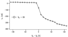
- E A [horizontal axis] and the relationship between the atomic current I A [vertical axis] measured by the first DC ammeter 16.
- the flux amount of dissociated nitrogen atoms (N and N * ) irradiated to the substrate 2 depends on the operating conditions of the RF excitation cell 4, particularly the high-frequency power supplied to the excitation coil 43 of the RF excitation cell 4 and the MBE film forming apparatus. It varies depending on the vapor pressure of the active species in one vacuum chamber 3, the temperature of the shroud in the vacuum chamber 3, and the like.
- the second sheet-like electrode 13 connects to the ground terminal.
- the current I B flowing toward 20 is measured by the second DC ammeter 17.
- the atomic current corresponds to the number of neutral dissociated nitrogen atoms attached to the inner surface of the first sheet-like electrode 12.
- the second DC ammeter 17 measures the current I B , it is a neutral dissociated nitrogen atom attached to the outer surface of the second sheet-like electrode 13 in addition to the current caused by the charged particles contained in the plasma. Means that the atomic current is included.
- the current due to the charged particles is also included in the current I A measured by the first DC ammeter 16 and becomes an error in measuring the flux amount. Therefore, it can be confirmed that there is an error in the atom current by the current I B of the second direct current meter 17.
- the current I A detected by the first DC ammeter 16 is converted into digital data by the A / D converter 21 and then taken into the PC 8.
- the PC 8 also functions as a control unit 81 and a calculation unit 82 of the atomic flux measurement device 10 in addition to the film formation control circuit 85 described above. These functions are realized by reading the software stored in the memory 83 and executing it by the CPU. The digital data taken into the PC 8 and stored in the memory 83 is displayed on the display 84 under the control of the control unit 81. The operator can check the value of the atomic current on the spot.
- the amount of atomic flux irradiated to the substrate 2 is monitored by the value of the atomic current flowing through the counter electrode body 11a.
- a table for converting the value of atomic current into the amount of atomic flux must be prepared and stored in the memory 83 in advance. There is.
- the calculation unit 82 converts the current value measured by the counter electrode body 11a into the amount of atomic flux, and when the value is displayed on the display 84, dissociated nitrogen atoms (N and N * on the spot ) ) Flux amount can be confirmed.
- the growth rate of the buffer layer when the single crystal Si 3 N 4 buffer layer is formed on the substrate 2 using the MBE film forming apparatus 1 described above and the value of the atomic current measured by the counter electrode body 11a Create a graph showing the correlation. If the data of the created graph is stored as a table in the memory of the film formation control circuit 85 (see FIG. 17), the film formation control circuit 85 uses the table data to measure the value of the atomic current measured by the counter electrode body 11a. Based on this, the growth rate of the single crystal Si 3 N 4 buffer layer can be controlled.
- the control unit 81 sets the voltages of the first and second DC power supplies 14 and 15 and controls ON / OFF of the first and second DC ammeters 16 and 17.
- the RF excitation cell 4 is attached to the cell port of the MBE film forming apparatus 1 shown in FIG. 17, while the silicon substrate 2 is fixed to the substrate holder 31 in the vacuum chamber 3, and the single crystal Si 3 N 4 is placed on the silicon substrate 2. Growing the buffer layer. At this time, high frequency power of 500 W is supplied to the RF excitation cell 4 to operate in the HB discharge mode.
- the flux of dissociated nitrogen atoms (base atom N and dissociated nitrogen atom N * ) released from the RF excitation cell 4 is used as the substrate.
- 2 is preferably irradiated indirectly, and the indirect irradiation is realized by any of the following methods.
- the first method is a method in which the traveling direction of the flux of dissociated nitrogen atoms released from the RF excitation cell 4 is closed with a shutter (not shown).
- a shutter not shown
- dissociated nitrogen atoms released from the orifice 44 of the RF excitation cell 4 repeatedly collide and reflect on the inner wall of the shutter and the growth chamber (vacuum chamber), and then from the peripheral edge of the shutter.
- the surface of the substrate 2 is irradiated with a flux with small leaked energy.
- the shutter is opened and the flux of dissociated nitrogen atoms released from the RF excitation cell 4 is repeatedly collided and reflected on the reflector 32 and the shroud provided in the vacuum chamber 3 before the substrate. 2 is irradiated.
- the counter electrode body 11 of the atomic flux measuring apparatus 10 is installed at a position adjacent to the substrate holder 31 and at a position outside the region connecting the orifice 44 of the RF excitation cell 4 and the surface of the substrate 2 with a straight line.
- the dissociated nitrogen atoms emitted from the RF excitation cell 2 are repeatedly collided and reflected by a shutter (not shown), a reflector 32, a shroud, etc. provided in front of the RF excitation cell 2, It enters the space of the counter electrode body 11a of the atomic flux measuring device 10.
- the dissociated nitrogen atoms adhere to the surfaces of the sheet-like electrodes 12 and 13 with a density corresponding to the thermal equilibrium vapor pressure in the space, and generate an atomic current between the electrodes.
- the atomic current measured by the atomic flux measuring device 10 is sent to the film forming control circuit 85 and used as data for controlling the thickness of the buffer layer.
- the value of the atomic current was measured using the atomic flux measurement device 10 while operating the RF excitation cell 4 under the following conditions.
- the relationship between the atomic current I A measured by the first DC ammeter 16 and the potential V A of the first sheet-like electrode 12 is shown in FIGS.
- Pressure in the RF excitation cell 4 about 100 Pa
- Vacuum degree of the vacuum chamber 3 4 ⁇ 10 ⁇ 3 Pa
- the graph of FIG. 7 shows that the electromotive force E A of the first DC power supply 14 is in the range of ⁇ 108 V to +108 V with the potential V B of the second terminal 19 held at ⁇ 175 V, ⁇ 75 V, and 0 V, respectively.
- the relationship between the potential V A of the first terminal ( ⁇ E A + V B ) and the atomic current I A measured by the first DC ammeter 16 when changed in FIG.
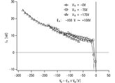
- the graph of FIG. 8 shows four curves.
- the first curve indicated by the symbol ⁇ indicates that the potential V B of the second terminal 19 is changed from ⁇ 800 V to 0 V while the electromotive force E A of the first DC power supply 14 is kept constant ( ⁇ 108 V).
- the fourth curve indicated by the symbol ⁇ is shown as a reference, and is based on the potential V A of the first terminal when the power is not supplied to the RF excitation cell 4 and the first DC ammeter 16.
- the relationship with the measured current I A ie, dark current
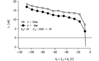
- the graph of FIG. 9 shows the potential V A of the first terminal and the first direct current when two types of counter electrode bodies 11a having different distances D (6 mm and 20 mm) between the pair of sheet electrodes 12 and 13 are used.
- the relationship with the atomic current I A measured by the ammeter 16 is shown.
- the counter electrode body with a large interval D indicated by a symbol of ⁇ has a larger value of the atomic current I A than the counter electrode body with a small interval D indicated by a symbol of ⁇ . This is presumably because the greater the distance D, the greater the amount of flux of dissociated nitrogen atoms (N * + N) present in the space of the counter electrode body 11a.
- FIG. 10 shows a basic configuration of an atomic flux measuring apparatus according to the second embodiment of the present invention.
- constituent elements having the same functions as those of the atomic flux measuring apparatus according to the first embodiment shown in FIG.
- an RF excitation cell 4 is added to explain the function of the electrode.
- the A / D converters 21 and 22 and the PC 8 that are not used in the description are omitted.
- the atomic flux measurement device of the present embodiment is the same as the atomic flux measurement device of Embodiment 1 except for the configuration of the counter electrode body.
- the counter electrode body 11b in the present embodiment has two sheet electrodes (hereinafter referred to as “sheet electrode”) made of a metal mesh sheet instead of the sheet electrodes 12 and 13 of the counter electrode body 11a in the first embodiment. 51 and 52) (referred to as “mesh electrodes”).
- the counter electrode body 11a in Embodiment 1 has no problem when measuring the flux amount of dissociated nitrogen atoms irradiated indirectly.
- the electrode since the electrode is formed of a sheet-like metal, when measuring the flux amount of dissociated nitrogen atoms irradiated directly from the RF excitation cell 4 to the substrate 2, the space portion of the counter electrode body depends on the electrode arrangement direction. The amount of flux entering will vary significantly. Further, most of the dissociated nitrogen atoms are reflected from the surface of the sheet-like electrode and fly out of the counter electrode body, and enter the space of the counter electrode body 11a to contribute to the atomic current with very few dissociated nitrogen atoms. As a result, the amount of flux of dissociated nitrogen atoms cannot be measured accurately.
- the dissociated nitrogen atom flux F irradiated from the RF excitation cell 4 passes through the gap between the mesh electrodes and enters the space of the counter electrode body 11b.
- Dissociated nitrogen atoms adhere to the surface of the electrode with a density corresponding to the thermal equilibrium vapor pressure, generating an atomic current.
- a negative bias potential V A ⁇ E A + V B is applied to the first mesh electrode 51 by the first DC power supply 14 and the second DC power supply 15.
- An atomic current I A based on the self-ionization of dissociated nitrogen atoms (N * + N) attached to the inner surface of the mesh electrode 51 flows between the mesh electrodes 51 and 52.
- the dissociated nitrogen atoms (N * + N) emitted from the RF excitation cell 4 are not limited to the flux that is incident from the peripheral openings of the mesh electrodes 51 and 52 by indirect irradiation. 4, the amount of flux that is directly irradiated and passed through the gap between the mesh electrodes 52 and sent into the space of the counter electrode body 11b can be measured.
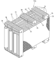
- FIG. 11 shows an example of a specific configuration of the counter electrode body 11b.
- the counter electrode body 11b is formed by winding two metal mesh sheets having different lengths so as to face each other with a gap therebetween.
- the surface area of the mesh electrodes 51 and 52 can be increased without increasing the volume of the counter electrode body.
- the amount of flux adhering to the inner surface of the mesh electrode 51 is increased, so that the value of the atomic current is increased, and the sensitivity of current measurement can be increased to increase the accuracy of detecting the flux amount.
- the mesh electrode 51 has a size of 140 mm (W) ⁇ 300 mm (L) and uses a # 100 (No. 100) stainless steel (SUS404) net
- the mesh electrode 52 has a size of 140 mm ( W) ⁇ 250 mm (L) and # 100 (100th) stainless steel (SUS404) net was used.
- These mesh electrodes 51 and 52 were wound while being opposed to each other with a gap (D) of 6 mm through a plurality of alumina sleeves 53 having a diameter of 6 mm as insulating spacers.
- the mesh electrode bodies 51 and 52 are spirally formed to increase the electrode area without increasing the volume, and the amount of dissociated nitrogen atoms adhering to the mesh electrode Can be increased. As a result, it is possible to increase the measurement sensitivity of the atomic current and thus increase the measurement accuracy of the atomic flux amount.
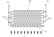
- FIG. 12 shows a basic configuration of an atomic flux measuring apparatus according to the third embodiment of the present invention.
- components having the same functions as those of the atomic flux measuring apparatuses according to the first and second embodiments are denoted by the same reference numerals and description thereof is omitted.
- an RF excitation cell 4 is added to explain the function of the electrodes.
- the A / D converters 21 and 22 and the PC 8 that are not used in the description are omitted.
- the counter electrode body 11c of the present embodiment uses two mesh electrodes 71 and 72 made of a metal mesh sheet.
- the counter electrode body 11c includes a third mesh electrode 73 made of a metal mesh sheet with a certain distance outside the second mesh electrode 72. It is arranged.
- the mesh electrode 73 By holding the third mesh electrode 73 at an appropriate potential, for example, the same potential as that of the mesh electrode 72, charged particles N 2 + , e ⁇ and the like contained in the flux F are incident on the mesh electrodes 71 and 72. Can be prevented to some extent. That is, the mesh electrode 73 functions as a filter that prevents noise and error current from being mixed into the atomic current flowing in the closed circuit including the mesh electrodes 71 and 72.
- an eliminator electrode pair 34 is arranged around the plasma emission port of the RF excitation cell 4 to charge the plasma flux. By deflecting the particles laterally, the charged particles can be prevented from being included in the flux F irradiated to the atomic flux measuring apparatus 10.
- the eliminator electrode pair 34 is composed of a pair of opposing electromagnets, and generates a static magnetic field that intersects with the plasma flux emitted from the RF excitation cell 4 to deflect the charged particles contained in the plasma flux in the lateral direction.
- the eliminator electrode pair 34 does not include charged particles in the flux F irradiated to the counter electrode body 11c from the RF excitation cell 4, the measurement error of the atomic current in the atomic flux measuring device can be reduced.
- the direction of the potential applied to the eliminator electrode pair 34 is changed by the switch 36 in the DC power source 35.
- FIG. 13 shows an example of a specific configuration of the counter electrode body 11c according to the present embodiment.
- FIG. 14 is a schematic circuit diagram of the counter electrode body 11c shown in FIG.
- the counter electrode body 11c shown in FIG. 13 differs from the counter electrode body 11b of the second embodiment shown in FIG. 11 in two points.
- the first difference will be described.
- the counter electrode body 11b two mesh electrodes 51 and 52 having a large area are wound to form a counter electrode body.
- a plurality of flat mesh electrodes 71 and 72 are alternately arranged in a state of being opposed to each other with a space therebetween.
- the counter electrode body 11c includes a first mesh electrode 71 in which flat metal mesh sheets are connected in a comb-like shape, and a second mesh electrode 72 having a similar configuration with a ceramic insulating spacer 74 interposed therebetween. It is configured to be combined in a misplaced manner.
- the insulating spacer 74 is fastened with a wire 75 so that the position does not shift.
- the flux F of dissociated nitrogen atoms released from the RF excitation cell 4 is not limited to indirect irradiation from the peripheral portion, but is also incident on the space formed between the electrodes by direct irradiation from the front surface of the mesh electrode 72.
- dissociated nitrogen atoms (N and N * ) flying into the space are attached to the inner surface of the first mesh electrode 71, an atomic current flows between the two electrodes.
- the counter electrode body 11b is designed to reduce the size of the counter electrode body by winding the mesh electrode, but the counter electrode body 11c is designed to reduce the size of the counter electrode body by stacking the mesh electrodes.
- the area of the mesh electrode is increased without increasing the volume of the counter electrode body, thereby increasing the amount of dissociated nitrogen atoms adhering to the electrode surface, and thus the detection sensitivity of the atomic current.
- the measurement accuracy of the dissociated nitrogen atom flux amount is improved.
- the second difference is that a comb-shaped third mesh electrode 73 is arranged in front of the counter electrode body.
- the mesh electrode 73 has a function of preventing noise and error current from being mixed into the atomic current flowing in the closed circuit including the mesh electrodes 71 and 72.
- the charged particles N 2 + , e ⁇ , and the like contained in the flux F flowing from the front of the counter electrode body are not perfect, but are prevented from entering the counter electrode body by the mesh electrode 73.
- the configuration of the counter electrode body 11c is not limited to that shown in FIG. In the counter electrode body shown in FIG. 13, the spacers 74 are arranged in three rows. However, as long as the insulation between the mesh electrodes can be maintained, the spacing may be maintained using a dedicated jig.
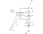
- FIG. 15 shows a basic configuration of an atomic flux measuring apparatus according to the fourth embodiment of the present invention.
- components having the same functions as those of the atomic flux measuring apparatuses according to the first to third embodiments are denoted by the same reference numerals and description thereof is omitted.
- the A / D converters 21 and 22 and the PC 8 that are not used in the description are omitted.
- the atomic flux measurement device of the present embodiment is the same as the atomic flux measurement device of Embodiments 1 and 2, except for the configuration of the counter electrode body.
- the counter electrode body 11d in the present embodiment uses a sheet-like electrode 91 similar to that in Embodiment 1 as the first sheet-like electrode held at the potential V A , and the second electrode held at the potential V B.
- a mesh electrode 92 similar to that of the second embodiment is used for the sheet-like electrode.
- the dissociated nitrogen atom flux F irradiated from the RF excitation cell 4 allows the gap between the mesh electrodes to pass. Since it passes through and enters the space portion of the counter electrode body 11d, the thermal equilibrium vapor pressure in the space portion increases. Dissociated nitrogen atoms adhere to the surface of the electrode with a density corresponding to the thermal equilibrium vapor pressure to generate an atomic current.
- the sheet-like electrode 91 similar to that of the first embodiment as the first sheet-like electrode held at the potential V A , the separation that has passed through the mesh electrode 92 and entered the space portion of the counter electrode body 11d. Since most of the nitrogen atoms come into contact with the surface of the sheet-like electrode 91, it can be expected that the value of the atomic current increases as compared with the counter electrode body 11b of the second embodiment.
- FIG. 16 schematically shows a circuit diagram of a specific configuration of the counter electrode body 11d according to the present exemplary embodiment.
- the specific configuration of the counter electrode body 11d is almost the same as the configuration of the counter electrode body 11c in the third embodiment shown in FIG. 13, and the first mesh electrode 93 and the second mesh electrode 92 are the same. Are alternately stacked.
- the first sheet-like electrode held at the potential V A is composed of the sheet-like electrode 91 and the mesh electrode 93.
- the third mesh electrode 73 of the counter electrode body 11c according to the third embodiment is removed, and instead, at a position opposite to the incident side of the atomic flux, a predetermined amount is provided.
- Flat sheet-like electrodes 91 are arranged at intervals. Note that the third mesh electrode 73 of the counter electrode body 11c may be left as it is.
- the value of the atomic current is larger than that of the counter electrode body 11c of the third embodiment. Can be expected to increase.
- the atomic flux measurement device of the present invention can increase the sensitivity of atomic current measurement by holding the potential of the first sheet-like electrode negative and further reducing the value thereof.
- the atomic current can be measured using a relatively inexpensive ammeter, and as a result, the manufacturing cost of the measuring device can be reduced.
- the surface area of the electrode can be increased without increasing the volume of the counter electrode body.
- a flux measuring device can be realized.
- the atomic flux measuring device 10 is used to monitor the flux amount of nitrogen active species (N and N * ) released from the RF excitation cell 4 has been described.
- the application of the atomic flux measuring device is not limited to this.
- Hydrogen gas H 2 or oxygen gas O 2 is supplied into the RF excitation cell 4 and a relatively large high frequency power is supplied to the excitation coil 43 of the RF excitation cell 4 to operate in the HB discharge mode. 4 releases a flux of dissociated hydrogen atoms (H * and H) and dissociated oxygen atoms (O * and O). After being emitted from the RF excitation cell 4, the flux of dissociated hydrogen atoms or dissociated oxygen atoms that repeatedly collided and reflected on the shroud, the reflector 32, etc. of the vacuum chamber 3 is incident on the counter electrode body 11 c, for example, and an atomic flux measurement device When the atomic current is measured at 10, the flux amount of dissociated hydrogen atoms and dissociated oxygen atoms can be calculated.
- the atomic flux measuring apparatus of the present invention is not limited to the case where a film is formed on the surface of the substrate in the vacuum chamber 3 of the MBE film forming apparatus, but also when an etching or oxidation process is performed in a vacuum chamber. Needless to say, this is applicable.
- the atomic flux measuring device 10 is arranged in the shutter port of the nitrogen RF excitation cell 2 of the MBE film forming apparatus at a position where the nitrogen dissociated atomic flux is not directly irradiated from the nitrogen RF excitation cell 4, that is, an indirect irradiation position.
- the activity-controlled nitrogen compound MBE film forming apparatus previously proposed by the inventors (see Japanese Patent Application Laid-Open No. 2008-78200) is used.
- the discharge mode of the nitrogen RF excitation cell 4 is alternately switched between the LB discharge mode and the HB discharge mode at an appropriate time interval (duty factor), and the nitrogen dissociated atoms generated during the HB discharge mode period in the LB discharge mode period.
- a single-crystal Si 3 N 4 buffer layer on the substrate surface is prevented by flushing atoms adsorbed on the shroud of the flux during the subsequent LB discharge mode to prevent deposition of nitrogen dissociated atoms on the cooled shroud surface. It is possible to effectively prevent a decrease in the growth rate.
Landscapes
- Chemical & Material Sciences (AREA)
- Engineering & Computer Science (AREA)
- Physics & Mathematics (AREA)
- Chemical Kinetics & Catalysis (AREA)
- Materials Engineering (AREA)
- Metallurgy (AREA)
- Organic Chemistry (AREA)
- General Physics & Mathematics (AREA)
- Theoretical Computer Science (AREA)
- Analytical Chemistry (AREA)
- Biochemistry (AREA)
- Pathology (AREA)
- Immunology (AREA)
- General Health & Medical Sciences (AREA)
- Life Sciences & Earth Sciences (AREA)
- Health & Medical Sciences (AREA)
- Electrochemistry (AREA)
- Spectroscopy & Molecular Physics (AREA)
- Plasma & Fusion (AREA)
- Mechanical Engineering (AREA)
- Crystallography & Structural Chemistry (AREA)
- Data Mining & Analysis (AREA)
- Software Systems (AREA)
- Databases & Information Systems (AREA)
- Mathematical Physics (AREA)
- General Engineering & Computer Science (AREA)
- Physical Vapour Deposition (AREA)
- Physical Deposition Of Substances That Are Components Of Semiconductor Devices (AREA)
Abstract
L'invention concerne un dispositif de mesure de flux atomique, compact et de faible coût, servant à mesurer un flux d'atomes dissociés généré par une décharge, ledit flux étant émis par une cellule de production de plasma dans un contenant. Le dispositif de mesure selon l'invention comprend des électrodes opposées constituées par une première et une deuxième électrode en feuille séparées par un intervalle déterminé et disposées quasiment en parallèle, une source d'alimentation en courant continu destinée à maintenir la première électrode en feuille à un potentiel négatif et à entraîner l'auto-ionisation des atomes attachés à la surface interne de ladite électrode en feuille, et destinée également à appliquer une tension continue pour créer un courant entre la première et la deuxième électrode, ainsi qu'un ampèremètre pour courant continu qui mesure le courant des électrons émis par les atomes dissociés du fait de l'auto-ionisation qui sont attachés à la surface interne de la première électrode en feuille.
Priority Applications (3)
| Application Number | Priority Date | Filing Date | Title |
|---|---|---|---|
| EP11803562.5A EP2592910A4 (fr) | 2010-07-05 | 2011-07-05 | Dispositif de mesure de flux atomique |
| JP2012523865A JP5816176B2 (ja) | 2010-07-05 | 2011-07-05 | 原子フラックス測定装置 |
| US13/733,594 US9658191B2 (en) | 2010-07-05 | 2013-01-03 | Atomic flux measurement device |
Applications Claiming Priority (4)
| Application Number | Priority Date | Filing Date | Title |
|---|---|---|---|
| JP2010-152658 | 2010-07-05 | ||
| JP2010152658 | 2010-07-05 | ||
| JP2010287599 | 2010-12-24 | ||
| JP2010-287599 | 2010-12-24 |
Related Child Applications (1)
| Application Number | Title | Priority Date | Filing Date |
|---|---|---|---|
| US13/733,594 Continuation US9658191B2 (en) | 2010-07-05 | 2013-01-03 | Atomic flux measurement device |
Publications (1)
| Publication Number | Publication Date |
|---|---|
| WO2012005228A1 true WO2012005228A1 (fr) | 2012-01-12 |
Family
ID=45441207
Family Applications (1)
| Application Number | Title | Priority Date | Filing Date |
|---|---|---|---|
| PCT/JP2011/065316 Ceased WO2012005228A1 (fr) | 2010-07-05 | 2011-07-05 | Dispositif de mesure de flux atomique |
Country Status (4)
| Country | Link |
|---|---|
| US (1) | US9658191B2 (fr) |
| EP (1) | EP2592910A4 (fr) |
| JP (1) | JP5816176B2 (fr) |
| WO (1) | WO2012005228A1 (fr) |
Families Citing this family (1)
| Publication number | Priority date | Publication date | Assignee | Title |
|---|---|---|---|---|
| WO2012005228A1 (fr) * | 2010-07-05 | 2012-01-12 | 学校法人同志社 | Dispositif de mesure de flux atomique |
Citations (3)
| Publication number | Priority date | Publication date | Assignee | Title |
|---|---|---|---|---|
| JP2008078200A (ja) | 2006-09-19 | 2008-04-03 | Doshisha | 金属窒素化合物の分子線エピタキシー成膜方法及び装置 |
| JP2009146755A (ja) | 2007-12-14 | 2009-07-02 | Doshisha | 原子フラックス測定装置 |
| JP2010232496A (ja) | 2009-03-27 | 2010-10-14 | Doshisha | シリコン基板上にSi3N4へテロエピタキシャルバッファ層を有する窒化シリコン基板の作製方法および装置 |
Family Cites Families (13)
| Publication number | Priority date | Publication date | Assignee | Title |
|---|---|---|---|---|
| US1421720A (en) * | 1920-06-03 | 1922-07-04 | Claudius H M Roberts | Method of and apparatus for detecting the presence of one gas in another |
| US3628139A (en) * | 1970-06-11 | 1971-12-14 | Ikor Inc | Method and apparatus for sensing particulate matter |
| US4137453A (en) * | 1976-08-31 | 1979-01-30 | Extranuclear Laboratories, Inc. | Methods and apparatus for improving electron capture detectors by collection of ions |
| US5591896A (en) * | 1995-11-02 | 1997-01-07 | Lin; Gang | Solid-state gas sensors |
| ES2355333T3 (es) * | 2001-08-22 | 2011-03-24 | Instrumentation Laboratory Company | Método y aparato para calibrar sensores . |
| US7372009B1 (en) * | 2002-12-18 | 2008-05-13 | The United States Of America As Represented By The Secretary Of The Navy | Solid-state thermal neutron detector |
| JP4676704B2 (ja) * | 2004-02-10 | 2011-04-27 | ソニー株式会社 | 機能性分子素子 |
| US8036738B2 (en) * | 2006-03-14 | 2011-10-11 | New Jersey Institute Of Technology | Iontophoretic transdermal drug delivery system based on conductive polyaniline membrane |
| KR100782370B1 (ko) * | 2006-08-04 | 2007-12-07 | 삼성전자주식회사 | 지연 전기장을 이용한 이온 에너지 분포 분석기에 근거한이온 분석 시스템 |
| US7645996B2 (en) * | 2006-10-27 | 2010-01-12 | Honeywell International Inc. | Microscale gas discharge ion detector |
| US20150155127A1 (en) * | 2007-11-27 | 2015-06-04 | Applied Nanotech Holdings, Inc. | Carbon nanotube-based ion source for particle generator |
| US7629575B2 (en) * | 2007-12-19 | 2009-12-08 | Varian, Inc. | Charge control for ionic charge accumulation devices |
| WO2012005228A1 (fr) * | 2010-07-05 | 2012-01-12 | 学校法人同志社 | Dispositif de mesure de flux atomique |
-
2011
- 2011-07-05 WO PCT/JP2011/065316 patent/WO2012005228A1/fr not_active Ceased
- 2011-07-05 EP EP11803562.5A patent/EP2592910A4/fr not_active Withdrawn
- 2011-07-05 JP JP2012523865A patent/JP5816176B2/ja active Active
-
2013
- 2013-01-03 US US13/733,594 patent/US9658191B2/en not_active Expired - Fee Related
Patent Citations (3)
| Publication number | Priority date | Publication date | Assignee | Title |
|---|---|---|---|---|
| JP2008078200A (ja) | 2006-09-19 | 2008-04-03 | Doshisha | 金属窒素化合物の分子線エピタキシー成膜方法及び装置 |
| JP2009146755A (ja) | 2007-12-14 | 2009-07-02 | Doshisha | 原子フラックス測定装置 |
| JP2010232496A (ja) | 2009-03-27 | 2010-10-14 | Doshisha | シリコン基板上にSi3N4へテロエピタキシャルバッファ層を有する窒化シリコン基板の作製方法および装置 |
Non-Patent Citations (1)
| Title |
|---|
| See also references of EP2592910A4 * |
Also Published As
| Publication number | Publication date |
|---|---|
| EP2592910A1 (fr) | 2013-05-15 |
| JP5816176B2 (ja) | 2015-11-18 |
| EP2592910A4 (fr) | 2014-08-13 |
| JPWO2012005228A1 (ja) | 2013-09-02 |
| US20130124124A1 (en) | 2013-05-16 |
| US9658191B2 (en) | 2017-05-23 |
Similar Documents
| Publication | Publication Date | Title |
|---|---|---|
| JP5826746B2 (ja) | パルスプラズマを用いた原子層エッチング | |
| CN114167482B (zh) | 等离子体处理的离子能量分析装置 | |
| US8124906B2 (en) | Method and apparatus for processing metal bearing gases | |
| JP4568321B2 (ja) | 冷陰極電離真空計 | |
| US20140062285A1 (en) | Method and Apparatus for a Large Area Inductive Plasma Source | |
| TWI821157B (zh) | 檢測離子的裝置及方法 | |
| CA3077841A1 (fr) | Stabilisation du plasma a decharge luminescente | |
| US20120160059A1 (en) | Method and Apparatus for Processing Metal Bearing Gases | |
| JP6929570B2 (ja) | 小型放電光イオン化検出器 | |
| EP1831425A2 (fr) | Procede et appareil de traitement de gaz porteurs de metal | |
| JP5816176B2 (ja) | 原子フラックス測定装置 | |
| KR20120027033A (ko) | 성막 장치 | |
| US20070193976A1 (en) | Plasma processing apparatus and plasma processing method | |
| CN101981652B (zh) | 紫外线发生装置以及使用该紫外线发生装置的照明装置 | |
| US20030178928A1 (en) | Monochromatic vacuum ultraviolet light source for photolithography applications based on a high-pressure microhollow cathode discharge | |
| US7351981B2 (en) | Method and apparatus for measuring purity of noble gases | |
| JP2009146755A (ja) | 原子フラックス測定装置 | |
| Jurczyk et al. | Illinois debris-mitigation EUV applications laboratory | |
| Jurczyk et al. | Illinois Debris-mitigation EUV Applications Laboratory (IDEAL) | |
| JP3818162B2 (ja) | 電子線照射処理装置 | |
| Gu | SIMS quantification of matrix and impurity species in III-nitride alloys | |
| JPWO2009123258A1 (ja) | 紫外線発生装置及びそれを用いた照明装置 | |
| Huber et al. | Sustainer enhancement of the VUV fluorescence in high-pressure xenon | |
| WO2022157905A1 (fr) | Spectromètre de masse | |
| Ohachi et al. | In situ measurement of adsorbed nitrogen atoms for PA‐MBE growth of group III nitrides on Si |
Legal Events
| Date | Code | Title | Description |
|---|---|---|---|
| 121 | Ep: the epo has been informed by wipo that ep was designated in this application |
Ref document number: 11803562 Country of ref document: EP Kind code of ref document: A1 |
|
| WWE | Wipo information: entry into national phase |
Ref document number: 2012523865 Country of ref document: JP |
|
| WWE | Wipo information: entry into national phase |
Ref document number: 2011803562 Country of ref document: EP |
|
| NENP | Non-entry into the national phase |
Ref country code: DE |