WO2012005263A1 - Dispositif de commande de la répartition du couple pour un véhicule à quatre roues motrices - Google Patents
Dispositif de commande de la répartition du couple pour un véhicule à quatre roues motrices Download PDFInfo
- Publication number
- WO2012005263A1 WO2012005263A1 PCT/JP2011/065397 JP2011065397W WO2012005263A1 WO 2012005263 A1 WO2012005263 A1 WO 2012005263A1 JP 2011065397 W JP2011065397 W JP 2011065397W WO 2012005263 A1 WO2012005263 A1 WO 2012005263A1
- Authority
- WO
- WIPO (PCT)
- Prior art keywords
- driving force
- wheel
- driving
- state
- vehicle
- Prior art date
- Legal status (The legal status is an assumption and is not a legal conclusion. Google has not performed a legal analysis and makes no representation as to the accuracy of the status listed.)
- Ceased
Links
Images



Classifications
-
- B—PERFORMING OPERATIONS; TRANSPORTING
- B60—VEHICLES IN GENERAL
- B60W—CONJOINT CONTROL OF VEHICLE SUB-UNITS OF DIFFERENT TYPE OR DIFFERENT FUNCTION; CONTROL SYSTEMS SPECIALLY ADAPTED FOR HYBRID VEHICLES; ROAD VEHICLE DRIVE CONTROL SYSTEMS FOR PURPOSES NOT RELATED TO THE CONTROL OF A PARTICULAR SUB-UNIT
- B60W30/00—Purposes of road vehicle drive control systems not related to the control of a particular sub-unit, e.g. of systems using conjoint control of vehicle sub-units
- B60W30/02—Control of vehicle driving stability
- B60W30/045—Improving turning performance
-
- B—PERFORMING OPERATIONS; TRANSPORTING
- B60—VEHICLES IN GENERAL
- B60K—ARRANGEMENT OR MOUNTING OF PROPULSION UNITS OR OF TRANSMISSIONS IN VEHICLES; ARRANGEMENT OR MOUNTING OF PLURAL DIVERSE PRIME-MOVERS IN VEHICLES; AUXILIARY DRIVES FOR VEHICLES; INSTRUMENTATION OR DASHBOARDS FOR VEHICLES; ARRANGEMENTS IN CONNECTION WITH COOLING, AIR INTAKE, GAS EXHAUST OR FUEL SUPPLY OF PROPULSION UNITS IN VEHICLES
- B60K23/00—Arrangement or mounting of control devices for vehicle transmissions, or parts thereof, not otherwise provided for
- B60K23/08—Arrangement or mounting of control devices for vehicle transmissions, or parts thereof, not otherwise provided for for changing number of driven wheels, for switching from driving one axle to driving two or more axles
- B60K23/0808—Arrangement or mounting of control devices for vehicle transmissions, or parts thereof, not otherwise provided for for changing number of driven wheels, for switching from driving one axle to driving two or more axles for varying torque distribution between driven axles, e.g. by transfer clutch
-
- F—MECHANICAL ENGINEERING; LIGHTING; HEATING; WEAPONS; BLASTING
- F16—ENGINEERING ELEMENTS AND UNITS; GENERAL MEASURES FOR PRODUCING AND MAINTAINING EFFECTIVE FUNCTIONING OF MACHINES OR INSTALLATIONS; THERMAL INSULATION IN GENERAL
- F16H—GEARING
- F16H48/00—Differential gearings
- F16H48/12—Differential gearings without gears having orbital motion
- F16H48/19—Differential gearings without gears having orbital motion consisting of two linked clutches
-
- B—PERFORMING OPERATIONS; TRANSPORTING
- B60—VEHICLES IN GENERAL
- B60K—ARRANGEMENT OR MOUNTING OF PROPULSION UNITS OR OF TRANSMISSIONS IN VEHICLES; ARRANGEMENT OR MOUNTING OF PLURAL DIVERSE PRIME-MOVERS IN VEHICLES; AUXILIARY DRIVES FOR VEHICLES; INSTRUMENTATION OR DASHBOARDS FOR VEHICLES; ARRANGEMENTS IN CONNECTION WITH COOLING, AIR INTAKE, GAS EXHAUST OR FUEL SUPPLY OF PROPULSION UNITS IN VEHICLES
- B60K17/00—Arrangement or mounting of transmissions in vehicles
- B60K17/34—Arrangement or mounting of transmissions in vehicles for driving both front and rear wheels, e.g. four wheel drive vehicles
- B60K17/344—Arrangement or mounting of transmissions in vehicles for driving both front and rear wheels, e.g. four wheel drive vehicles having a transfer gear
-
- B—PERFORMING OPERATIONS; TRANSPORTING
- B60—VEHICLES IN GENERAL
- B60K—ARRANGEMENT OR MOUNTING OF PROPULSION UNITS OR OF TRANSMISSIONS IN VEHICLES; ARRANGEMENT OR MOUNTING OF PLURAL DIVERSE PRIME-MOVERS IN VEHICLES; AUXILIARY DRIVES FOR VEHICLES; INSTRUMENTATION OR DASHBOARDS FOR VEHICLES; ARRANGEMENTS IN CONNECTION WITH COOLING, AIR INTAKE, GAS EXHAUST OR FUEL SUPPLY OF PROPULSION UNITS IN VEHICLES
- B60K17/00—Arrangement or mounting of transmissions in vehicles
- B60K17/34—Arrangement or mounting of transmissions in vehicles for driving both front and rear wheels, e.g. four wheel drive vehicles
- B60K17/348—Arrangement or mounting of transmissions in vehicles for driving both front and rear wheels, e.g. four wheel drive vehicles having differential means for driving one set of wheels, e.g. the front, at one speed and the other set, e.g. the rear, at a different speed
- B60K17/35—Arrangement or mounting of transmissions in vehicles for driving both front and rear wheels, e.g. four wheel drive vehicles having differential means for driving one set of wheels, e.g. the front, at one speed and the other set, e.g. the rear, at a different speed including arrangements for suppressing or influencing the power transfer, e.g. viscous clutches
- B60K17/3515—Arrangement or mounting of transmissions in vehicles for driving both front and rear wheels, e.g. four wheel drive vehicles having differential means for driving one set of wheels, e.g. the front, at one speed and the other set, e.g. the rear, at a different speed including arrangements for suppressing or influencing the power transfer, e.g. viscous clutches with a clutch adjacent to traction wheel, e.g. automatic wheel hub
-
- B—PERFORMING OPERATIONS; TRANSPORTING
- B60—VEHICLES IN GENERAL
- B60W—CONJOINT CONTROL OF VEHICLE SUB-UNITS OF DIFFERENT TYPE OR DIFFERENT FUNCTION; CONTROL SYSTEMS SPECIALLY ADAPTED FOR HYBRID VEHICLES; ROAD VEHICLE DRIVE CONTROL SYSTEMS FOR PURPOSES NOT RELATED TO THE CONTROL OF A PARTICULAR SUB-UNIT
- B60W10/00—Conjoint control of vehicle sub-units of different type or different function
- B60W10/12—Conjoint control of vehicle sub-units of different type or different function including control of differentials
- B60W10/16—Axle differentials, e.g. for dividing torque between left and right wheels
-
- B—PERFORMING OPERATIONS; TRANSPORTING
- B60—VEHICLES IN GENERAL
- B60W—CONJOINT CONTROL OF VEHICLE SUB-UNITS OF DIFFERENT TYPE OR DIFFERENT FUNCTION; CONTROL SYSTEMS SPECIALLY ADAPTED FOR HYBRID VEHICLES; ROAD VEHICLE DRIVE CONTROL SYSTEMS FOR PURPOSES NOT RELATED TO THE CONTROL OF A PARTICULAR SUB-UNIT
- B60W2720/00—Output or target parameters relating to overall vehicle dynamics
- B60W2720/40—Torque distribution
- B60W2720/403—Torque distribution between front and rear axle
-
- B—PERFORMING OPERATIONS; TRANSPORTING
- B60—VEHICLES IN GENERAL
- B60W—CONJOINT CONTROL OF VEHICLE SUB-UNITS OF DIFFERENT TYPE OR DIFFERENT FUNCTION; CONTROL SYSTEMS SPECIALLY ADAPTED FOR HYBRID VEHICLES; ROAD VEHICLE DRIVE CONTROL SYSTEMS FOR PURPOSES NOT RELATED TO THE CONTROL OF A PARTICULAR SUB-UNIT
- B60W2720/00—Output or target parameters relating to overall vehicle dynamics
- B60W2720/40—Torque distribution
- B60W2720/406—Torque distribution between left and right wheel
-
- F—MECHANICAL ENGINEERING; LIGHTING; HEATING; WEAPONS; BLASTING
- F16—ENGINEERING ELEMENTS AND UNITS; GENERAL MEASURES FOR PRODUCING AND MAINTAINING EFFECTIVE FUNCTIONING OF MACHINES OR INSTALLATIONS; THERMAL INSULATION IN GENERAL
- F16H—GEARING
- F16H48/00—Differential gearings
- F16H48/20—Arrangements for suppressing or influencing the differential action, e.g. locking devices
- F16H2048/204—Control of arrangements for suppressing differential actions
- F16H2048/205—Control of arrangements for suppressing differential actions using the steering as a control parameter
Definitions
- a part of the driving force directed to the main driving wheel can be transmitted to the sub driving wheel under control, and the part of the driving force is distributed and output to the left sub driving wheel and the right sub driving wheel under control.
- the present invention relates to a driving force distribution control device for a four-wheel drive vehicle.
- Patent Document 1 As a driving force distribution control device for a four-wheel drive vehicle, for example, a device as described in Patent Document 1 has been proposed.
- This proposed technology compares the yaw rate, which is the turning behavior of the vehicle, with the target yaw rate, and when in the oversteer state, the driving force between the inner and outer wheels in the turning direction is such that the actual yaw rate is too small and approaches the target yaw rate.
- the vehicle is in an understeer state with a difference, the actual yaw rate is too small, and the driving force difference is provided between the inner and outer wheels in the turning direction so as to approach the target yaw rate.
- the actual yaw rate can be converged to the target yaw rate even if the actual yaw rate deviates from the target yaw rate by feedback of the yaw rate.
- the excessive actual yaw rate is reduced so as to approach the target yaw rate during oversteer, meaning that the driving force on the inner ring side in the turning direction is increased, Since an excessively low actual yaw rate is increased so as to approach the target yaw rate during understeering, this means that the driving force on the outer wheel side in the turning direction is increased, and the following problems occur.
- the wheel load is reduced by the load movement on the inner side in the turning direction, and the inner wheel in the turning direction easily slips and cannot transmit a large driving force.
- the driving force on the inner ring side in the turning direction is increased during oversteering as in the prior art, the increased driving force cannot be reliably transmitted to the inner ring in the turning direction, and a predetermined effect cannot be obtained.
- the turning stability of the vehicle is impaired by the driving slip of the inner ring in the turning direction.
- the driver gives a steering angle for canceling the vehicle yaw rate that accompanies this road surface inclination (to prevent the actual yaw rate from occurring in the vehicle). Since the yaw rate is not generated even though the steering is performed, it is determined that the comparison result between the target yaw rate obtained from the steering and the actual yaw rate is an understeer state.
- the understeer determination is performed, in the conventional driving force distribution control, the driving force on the outer wheel side in the steering direction is increased so that the yaw rate equal to the target yaw rate is generated from the state where the yaw rate is not generated. Gives a yaw moment that runs up the road surface.
- the driver steered to cancel the vehicle yaw rate associated with the slope of the cant road surface, and did not steer to hope for a turn.
- the driver is confused.
- the present invention has reached the conclusion that it is better not to perform the driving force difference control between the inner and outer wheels at the time of oversteer determination or understeer determination by comparing the target yaw rate and the actual yaw rate, It is an object of the present invention to provide a driving force distribution control device for a four-wheel drive vehicle that embodies this and can solve the above problems.
- the driving force distribution control device for a four-wheel drive vehicle is: A driving force of a four-wheel drive vehicle capable of transmitting a part of the driving force toward the main driving wheel to the sub driving wheel under control, and distributing and outputting the total driving force to the sub driving wheel to the left and right sub driving wheels under control.
- the distribution control device is characterized by the following oversteer determination means and oversteer left / right driving force difference control means, or Kawasako provided with understeer determination means and understeer left / right driving force difference control means.
- the oversteer determination means determines that the actual turning behavior is excessive with respect to the target turning behavior obtained from the vehicle driving state
- the left and right driving force difference control means for oversteer is for setting the driving force difference between the left and right auxiliary driving wheels to zero when the oversteer determining means determines that it is in an oversteer state.
- the understeer determination means determines an understeer state where the actual turning behavior is insufficient with respect to the target turning behavior
- the understeer left / right driving force difference control means sets the driving force difference between the left and right auxiliary driving wheels to zero when the understeer determination means determines that it is in an understeer state.
- a large driving force is not directed to the auxiliary driving wheel on the inner side in the turning direction in which the wheel load is reduced during the oversteer determination. Therefore, in addition to the wheel load of the auxiliary drive wheel being reduced, a large driving force is not transmitted and the drive slip does not occur, thereby avoiding the problem that the turning stability of the vehicle is impaired by this drive slip. can do.
- FIG. 1 is a schematic plan view showing a wheel drive system of a four-wheel drive vehicle equipped with a drive force distribution control device according to an embodiment of the present invention, together with the four-wheel drive control system, as viewed from above the vehicle.
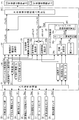
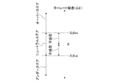
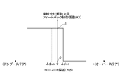
- FIG. 2 is a functional block diagram showing the four-wheel drive controller in FIG. 3 is a flowchart showing a feedback control coefficient determination program executed by a yaw rate deviation calculation unit and a feedback control coefficient calculation unit in FIG. It is an area diagram showing an oversteer area, an understeer area, and a neutral steer area. It is a change characteristic figure of the feedback control coefficient for rear-wheel total driving force.
- FIG. 3 is a flowchart showing a process when a left and right rear wheel target driving force calculation unit in FIG. 2 calculates a left and right rear wheel target driving force.
- FIG. 1 is a schematic plan view showing a wheel drive system of a four-wheel drive vehicle provided with a drive force distribution control device according to an embodiment of the present invention, together with the four-wheel drive control system, as viewed from above the vehicle.
- 1L and 1R respectively indicate left and right front wheels as main drive wheels
- 2L and 2R respectively indicate left and right rear wheels as auxiliary drive wheels.
- driving force means “torque value”, not power.
- a transmission transaxle including a differential gear device 4a
- the left and right front wheels 1L and 1R are used for driving.
- a part of the driving force directed to the left and right front wheels 1L and 1R after being shifted by the transmission 4 is redirected by the transfer 6 and directed to the left and right rear wheels 2L and 2R.
- the transmission system for this is configured as follows:
- the transfer 6 includes a bevel gear set including an input side hypoid gear 6a and an output side hypoid gear 6b.
- the input side hypoid gear 6a is coupled to the differential gear case 4a so as to rotate together with the differential gear case which is an input rotation member of the differential gear device 4a.
- the front end of the propeller shaft 7 is coupled to the output side hypoid gear 6b, and the propeller shaft 7 extends rearward toward the left and right rear wheel driving force distribution unit 8.
- the transfer 6 determines the gear ratio of the bevel gear set including the hypoid gear 6a and the output side hypoid gear 6b so that a part of the driving force directed to the left and right front wheels 1L and 1R is accelerated and output to the propeller shaft 7.
- the left and right rear wheel driving force distribution unit 8 includes a center shaft 10 extending in the axial direction of the shafts 9L and 9R between the axle shafts 9L and 9R of the left and right rear wheels 2L and 2R.
- the left and right rear wheel driving force distribution unit 8 is further disposed between the center shaft 10 and the left rear wheel axle shaft 9L, and the left rear wheel side clutch (the left auxiliary driving wheel side friction element) for controlling the coupling between the shafts 10 and 9L.
- 11L Between the center shaft 10 and the right rear wheel axle shaft 9R, there is provided a right rear wheel side clutch (right auxiliary driving wheel side friction element) 11R for controlling coupling between the shafts 10 and 9R.
- the rear end of the propeller shaft 7 extending from the transfer 6 to the rear of the vehicle and the center shaft 10 are drive-coupled via a bevel gear type final reduction gear 12 including an input side hypoid gear 12a and an output side hypoid gear 12b.
- the speed reduction ratio of the final reduction gear 12 is related to the left and right front wheels 1L and 1R in relation to the speed increasing gear ratio of the transfer 6 (the speed increasing gear ratio of the bevel gear set including the hypoid gear 6a and the output side hypoid gear 6b).
- the gear ratio is such that a part of the driving force toward the center shaft 10 is directed to increase the speed downward
- the total gear ratio of the transfer 6 and the final reduction gear 12 is set so that the center shaft 10 rotates at an increased speed with respect to the left and right front wheels 1L and 1R.
- the transfer speed is controlled so that the rotational speed of the center shaft 10 does not become lower than the rotational speed of the outer rear wheel 2L (or 2R) in the turning direction even during such turning, and the driving force distribution control is not disabled.
- the total gear ratio of 6 and the final reduction gear 12 is determined as described above, and the center shaft 10 is rotated at a higher speed as described above. Due to the accelerated rotation of the center shaft 10, drive force distribution control described later can be performed as intended.
- the rotational power from the engine 3 reaches the left and right front wheels 1L and 1R under the shift by the transmission (transaxle) 4, and drives these left and right front wheels 1L and 1R. .
- the vehicle is capable of four-wheel drive traveling by driving the left and right front wheels 1L and 1R and driving the left and right rear wheels 2L and 2R.
- the front and rear wheel drive force distribution control is performed via the total engagement force control of the left rear wheel side clutch 11L and the right rear wheel side clutch 11R.
- the left rear wheel side clutch is used to improve the turning performance of the vehicle and to control the behavior of the vehicle so that the actual behavior of the vehicle (actual yaw rate, etc.) is as intended according to the driving state and driving conditions of the vehicle.
- the left and right wheel driving force distribution control can be performed through the engagement force control of the 11L and right rear wheel side clutch 11R.
- the fastening force control system for the left rear wheel side clutch 11L and the right rear wheel side clutch 11R is as follows.
- Each of the left rear wheel side clutch 11L and the right rear wheel side clutch 11R is an electromagnetic type in which the fastening force is determined according to the supply current, and the fastening force of these clutches 11L and 11R is respectively a four wheel drive (4WD) controller 21.
- the above-mentioned front and rear wheel driving force is controlled by electronically controlling the supply current to the clutches 11L and 11R so as to obtain the fastening force corresponding to the target driving force TcL and TcR of the left and right rear wheels 2L and 2R obtained as described later in It is assumed that distribution control and left and right wheel driving force distribution control are performed.
- a signal from the lateral acceleration sensor 29 for detecting the lateral acceleration Gy of the vehicle is input.
- the four-wheel drive controller 21 calculates the left rear wheel target drive force TcL and the right rear wheel target drive force TcR for front and rear wheel drive force distribution control and left and right wheel drive force distribution control, which will be described in detail later. Operate, Assume that the fastening force (current) of the left rear wheel side clutch 11L and the right rear wheel side clutch 11R is electronically controlled so that the driving forces of the left and right rear wheels 2L, 2R coincide with the target driving forces TcL, TcR.
- ⁇ Driving force distribution control The procedure for determining the front and rear wheel driving force distribution control and the left and right wheel driving force distribution control executed by the four-wheel drive controller 21, that is, the left rear wheel target driving force TcL and the right rear wheel target driving force TcR will be described below.
- the four-wheel drive controller 21 is as shown in FIG. 2 in a functional block diagram, and includes an input signal processing unit 31, a rear wheel total driving force calculating unit 32, a left and right rear wheel driving force difference calculating unit 33, The feedback control unit 34 and the left and right rear wheel target driving force calculation unit 35 are configured.
- the input signal processing unit 31 includes a wheel speed sensor group 22, an accelerator opening sensor 23, a steering angle sensor 24, a transmission output rotation sensor 25, an engine rotation sensor 26, a yaw rate sensor 27, a longitudinal acceleration sensor 28, and a lateral acceleration sensor 29. Noise is removed from the detection signal, and preprocessing is performed so that it can be used for later-described computation.
- the engine torque Te is estimated by the engine torque estimating unit 36 using the engine speed Ne and the accelerator opening APO.
- the transmission gear ratio calculation unit 37 calculates the transmission gear ratio ⁇ using the engine speed Ne and the transmission output speed No.
- the rear wheel total driving force calculation unit 32 obtains a total driving force target value rTcLR (hereinafter referred to as total driving force rTcLR) for the left and right rear wheels 2L and 2R as follows, for example.
- rTcLR total driving force target value rTcLR
- the input torque Ti to the differential gear device 4a is calculated from the engine torque Te and the transmission gear ratio ⁇ .
- the average speed of the left and right front wheels and the average speed of the left and right rear wheels are obtained, and the driving slip degree of the left and right front wheels 1L and 1R estimated by comparing the two Rotation difference), longitudinal acceleration Gx, and accelerator opening APO, determine how much of the above input torque Ti should be directed to the left and right rear wheels 2L, 2R, and total drive to these rear wheels Force rTcLR.
- the total driving force rTcLR to the rear wheels needs to be increased to suppress the driving slip as the degree of the front wheel slip increases, and the driver increases as the longitudinal acceleration Gx and the accelerator opening APO increase. Since driving force is required, the total driving force rTcLR for the rear wheels is increased to meet this demand.
- the left and right rear wheel driving force difference calculating unit 33 includes a steady control calculating unit 33a and a transient control calculating unit 33b, and calculates a driving force difference target value r ⁇ TcLR between the left and right rear wheels 2L and 2R (hereinafter referred to as a driving force difference r ⁇ TcLR). For example, it is obtained as follows.
- the steady control calculation unit 33a obtains the left and right rear wheel driving force difference steady control c ⁇ TcLR for the vehicle turning behavior that the driver regularly requests as follows. That is, the longitudinal acceleration Gx generated in the vehicle is estimated from the engine torque Te and the transmission gear ratio ⁇ , and the lateral acceleration Gy generated in the vehicle is determined from the steering angle ⁇ and the wheel speed Vw (vehicle speed VSP). Estimate the difference between the left and right rear wheel driving force required to resolve the understeer state of the vehicle (a state where the actual turning behavior is insufficient with respect to the target turning behavior) as determined from the combination of the estimated longitudinal acceleration Gx and lateral acceleration Gy. Left and right rear wheel driving force difference steady control amount c ⁇ TcLR is determined.
- the reason why the estimated value is used instead of the detected value of the longitudinal acceleration Gx and the estimated value is used instead of the detected value of the lateral acceleration Gy is that the steady-state control calculation unit 33a is a feedforward control system and the detected value is a result value. This is because the estimated value matches the actual state of control.
- the rear wheel driving force difference steady control component c ⁇ TcLR is increased, As the longitudinal acceleration Gx increases, the understeer tendency of the vehicle becomes stronger, so the left and right rear wheel driving force difference steady control component c ⁇ TcLR increases.
- the transient control calculation unit 33b calculates the left and right rear wheel driving force difference transient control amount d ⁇ TcLR for the turning response that the driver transiently requests based on the change speed of the steering angle ⁇ under the current vehicle speed VSP as follows: So ask. That is, the target yaw rate t ⁇ desired by the driver is calculated from the wheel speed Vw (vehicle speed) and the steering angle ⁇ , and the upper limit is set according to the lateral acceleration Gy.
- the target yaw rate t ⁇ is differentiated to obtain the change rate dt ⁇ of the target yaw rate t ⁇ , and the left and right values that are target values for the turning response that the driver transiently requests from the change rate dt ⁇ of the target yaw rate t ⁇ .
- the rear wheel drive force difference transient control d ⁇ TcLR is obtained by map search.
- the left and right rear wheel driving force difference transient control amount d ⁇ TcLR has a larger value corresponding to a higher turning response as the change speed dt ⁇ of the target yaw rate t ⁇ is higher.
- the reason why the change rate dt ⁇ of the target yaw rate t ⁇ is used instead of the change rate of the yaw rate detection value ⁇ is that the transient control calculation unit 33b is a feedforward control system, and the estimated value is larger than the detection value ⁇ as a result value. This is because the target yaw rate t ⁇ that matches the actual condition of control.
- the left and right rear wheel driving force difference calculating unit 33 is the right and left rear wheel driving force difference steady control amount c ⁇ TcLR obtained as described above by the steady control calculating unit 33a and the right and left rear wheels obtained as described above by the transient control calculating unit 33b.
- the sum of the driving force difference transient control amount d ⁇ TcLR is determined as the left and right rear wheel driving force difference r ⁇ TcLR that should be the target when the vehicle turns.
- the actual turning behavior (actual yaw rate ⁇ ) actually generated by the vehicle due to the left / right rear wheel driving force difference r ⁇ TcLR is the target turning behavior requested by the driver through steering operation due to disturbances such as crosswinds. May not match (target yaw rate t ⁇ ).
- the feedback control unit 34 corrects the rear wheel total driving force rTcLR and the rear wheel driving force difference r ⁇ TcLR as follows when the actual yaw rate ⁇ and the target yaw rate t ⁇ do not coincide with each other to obtain a final rear wheel total.
- the driving force TcLR and the rear wheel driving force difference ⁇ TcLR are configured as follows.
- the feedback control unit 34 includes a target yaw rate calculation unit 34a, a yaw rate deviation calculation unit 34b, and a feedback control coefficient calculation unit 34c.
- the target yaw rate calculation unit 34a calculates a target yaw rate t ⁇ desired by the driver from the steering angle ⁇ , the lateral acceleration Gy, and the vehicle speed VSP obtained based on the wheel speed Vw.
- the yaw rate deviation calculating unit 34b and the feedback control coefficient calculating unit 34c execute the control program shown in FIG. 3, and the feedback control coefficient K1 (0 or 1) for the rear wheel total driving force rTcLR and the rear wheel driving force difference r ⁇ TcLR Feedback control coefficient K2 (0 or 1) is determined.
- the feedback control coefficient K1 is used to calculate the final rear wheel total driving force TcLR after correction by multiplying the rear wheel total driving force rTcLR
- the feedback control coefficient K2 is used to determine the final rear wheel driving force difference ⁇ TcLR after correction by multiplying the rear wheel driving force difference r ⁇ TcLR.
- the feedback control coefficient calculation unit 34c is in an excessive oversteer state ( ⁇ > t ⁇ + dead zone) with the actual yaw rate ⁇ exceeding the dead zone with respect to the target yaw rate t ⁇ based on the yaw rate deviation ⁇ in steps S12 to S15 in FIG. Or understeer state where the actual yaw rate ⁇ is insufficient beyond the dead zone relative to the target yaw rate t ⁇ ( ⁇ ⁇ t ⁇ dead zone), or a neutral steer state where these excess / deficiency does not occur (t ⁇ dead zone ⁇ ⁇ ⁇ t ⁇ + dead zone) According to the result, feedback control coefficients K1 and K2 are determined in steps S16 to S18.
- the feedback control coefficient calculation unit 34c first determines in step S12 whether the yaw rate deviation ⁇ is a positive value above this with reference to 0 in FIG. 4, and in step S13, the yaw rate deviation ⁇ is Check whether the negative value is lower than 0 with reference to 0 in FIG.
- step S12 If it is determined in step S12 that the yaw rate deviation ⁇ is ⁇ > 0, whether or not the actual yaw rate ⁇ is in an excessive oversteer state ( ⁇ > t ⁇ + dead zone) exceeding the dead zone illustrated in FIG. 4 with respect to the target yaw rate t ⁇ in step S14. Therefore, it is determined whether the yaw rate deviation
- step S13 When it is determined in step S13 that the yaw rate deviation ⁇ is ⁇ ⁇ 0, whether or not the actual yaw rate ⁇ exceeds the dead zone illustrated in FIG. 4 with respect to the target yaw rate t ⁇ and is in an excessive understeer state ( ⁇ ⁇ t ⁇ dead zone).
- step S13 and step S15 correspond to the understeer determination means in the present invention.
- the dead zone corresponds to, for example, a slight yaw rate deviation ⁇ such that the driver does not feel a change in the yaw rate of the vehicle.
- at step S15 that is, the actual yaw rate ⁇ has exceeded the dead zone with respect to the target yaw rate t ⁇ .
- step S16 since the vehicle is in the neutral steer state, neither the oversteer state nor the understeer state, the control proceeds to step S16, and the feedback control coefficient K1 for the rear wheel total driving force rTcLR is shown in FIG. As shown, it is set to 1, and the feedback control coefficient K2 for the rear wheel driving force difference r ⁇ TcLR is also set to 1.
- the feedback control coefficient calculation unit 34c determines that the oversteer state (
- the feedback control coefficient K1 for rTcLR is set to 0 as shown in FIG. 5, and the feedback control coefficient K2 for the rear wheel driving force difference r ⁇ TcLR is also set to 0.
- the feedback control coefficient calculation unit 34c uses the rear wheel total driving force rTcLR in step S18 corresponding to the left steering left / right driving force difference control means.
- the feedback control coefficient K1 is 1 as shown in FIG. 5, and the feedback control coefficient K2 for the rear wheel driving force difference r ⁇ TcLR is 0.
- the left and right rear wheel target driving force calculation unit 35 satisfies both the left and right rear wheel total driving force TcLR and the left and right rear wheel driving force difference ⁇ TcLR, which should be the final target after correction, by the process shown in FIG.
- the left rear wheel target driving force TcL and the right rear wheel target driving force TcR are obtained.
- step S11 the final rear wheel total driving force TcLR corrected by the feedback control is read
- step S12 the final left and right rear wheel driving force difference ⁇ TcLR corrected by the feedback control is read.
- step S13 the right and left equal distribution amount TcLR / 2 of the rear wheel total driving force TcLR read in step S11 is obtained.
- step S14 the right and left equal distribution amount ⁇ TcLR / of the rear wheel driving force difference ⁇ TcLR read in step S12. Ask for 2.
- the target driving force TcOUT for the rear wheel outside the turning direction and the target driving force TcIN for the rear wheel inside the turning direction are used to achieve both the rear wheel total driving force TcLR and the rear wheel driving force difference ⁇ TcLR. These are the driving force of the rear wheel outside the turning direction and the driving force of the rear wheel inside the turning direction.
- step S21 based on the outer wheel side target driving force TcOUT of the turning direction outer rear wheel and the inner wheel side target driving force TcIN of the turning direction inner rear wheel obtained as described above, the left rear wheel target driving force TcL and the right
- the rear wheel target driving force TcR is determined according to the following procedure. First, in step S21, it is determined whether the vehicle is turning left or right based on the steering angle ⁇ and the yaw rate ⁇ .
- step S22 the target driving force TcIN of the left rear wheel that is the inner wheel in the turning direction is set to the target driving force TcIN of the inner wheel and the target drive of the right rear wheel that is the outer wheel in the turning direction.
- the outer ring side target driving force TcOUT is set to the force TcR.
- step S23 the outer wheel side target driving force TcOUT is set to the target driving force TcL of the left rear wheel that is the outer wheel in the turning direction, and the right rear wheel that is the inner wheel in the turning direction.
- the target driving force TcIN on the inner ring side is set to the target driving force TcR.
- the four-wheel drive controller 21 in FIG. 1 has the left rear wheel target drive force TcL and the right rear determined by the computing unit 35 in FIG.
- the current supplied to the left rear wheel side clutch 11L and the right rear wheel side clutch 11R is controlled so as to correspond to the wheel target driving force TcR.
- the wheel load is reduced by the load movement on the inner wheel side in the turning direction, so that the inner rear wheel easily slips and cannot transmit a large driving force.
- it is necessary to increase the driving force of the inner rear wheel.
- the inner rear wheel cannot transmit a large driving force due to a decrease in wheel load, but if this is ignored and the driving force to the inner rear wheel is increased to eliminate the oversteer state,
- the inner rear wheel causes a drive slip, which not only makes it impossible to eliminate the essential oversteer state, but also causes a problem that the turning stability of the vehicle is impaired.
- step S18 when it is determined in step S15 in FIG. 3 that the understeer state (
- the feedback control coefficient K2 for the difference r ⁇ TcLR is set to 0, the four-wheel drive running state in which the driving force is transmitted to the rear wheels as calculated by the computing unit 32 is maintained, and the driving force distribution of the left and right rear wheels is maintained. Is made the same regardless of the calculation result in the calculation unit 33, the following effects can be obtained.
- the determination of the steer state by comparing the target yaw rate t ⁇ obtained from the steering and the actual yaw rate ⁇ is the same as the under steer state as in step S15 of the present embodiment. Make a decision.
- the conventional driving force distribution control increases the driving force of the rear wheels in the steering direction so that the same yaw rate as the target yaw rate is generated when no yaw rate is generated. A yaw moment that runs up the cant surface is given.
- the driver steered to cancel the vehicle yaw rate associated with the slope of the cant road surface, and did not steer to hope for a turn.
- the driver is confused.
- step S15 when the understeer state (
- ) is determined in step S15, the driving force distribution of the left and right rear wheels is made the same by K2 0 in step S18.
- K2 0 in step S18.
- the feedback control coefficient K1 for the rear wheel total driving force is switched from 1 to 0 when the yaw rate deviation ⁇ exceeds the oversteer judgment value ⁇ os, and the yaw rate deviation ⁇ is oversteered.
- the feedback control coefficient K1 for the rear wheel total driving force is switched from 0 to 1 at the time of neutral steer determination that decreases to the determination value ⁇ os.
- the switching is gradually switched according to the yaw rate deviation ⁇ so that the rear wheel total driving force TcLR (see FIG. 2) does not change suddenly between the calculated value rTcLR and 0 in the calculating unit 32. It is preferable in order to prevent a sense of incongruity.
Landscapes
- Engineering & Computer Science (AREA)
- Mechanical Engineering (AREA)
- Transportation (AREA)
- General Engineering & Computer Science (AREA)
- Automation & Control Theory (AREA)
- Chemical & Material Sciences (AREA)
- Combustion & Propulsion (AREA)
- Arrangement And Driving Of Transmission Devices (AREA)
- Arrangement And Mounting Of Devices That Control Transmission Of Motive Force (AREA)
Abstract
Priority Applications (3)
| Application Number | Priority Date | Filing Date | Title |
|---|---|---|---|
| EP11803597.1A EP2591937B1 (fr) | 2010-07-09 | 2011-07-05 | Dispositif de commande de la répartition du couple pour un véhicule à quatre roues motrices |
| CN201180031935.0A CN102958735B (zh) | 2010-07-09 | 2011-07-05 | 四轮驱动车辆的驱动力分配控制装置 |
| US13/806,684 US8948991B2 (en) | 2010-07-09 | 2011-07-05 | Left-right wheel drive force distribution control apparatus for a vehicle |
Applications Claiming Priority (2)
| Application Number | Priority Date | Filing Date | Title |
|---|---|---|---|
| JP2010-156665 | 2010-07-09 | ||
| JP2010156665A JP5257414B2 (ja) | 2010-07-09 | 2010-07-09 | 四輪駆動車両の駆動力配分制御装置 |
Publications (1)
| Publication Number | Publication Date |
|---|---|
| WO2012005263A1 true WO2012005263A1 (fr) | 2012-01-12 |
Family
ID=45441241
Family Applications (1)
| Application Number | Title | Priority Date | Filing Date |
|---|---|---|---|
| PCT/JP2011/065397 Ceased WO2012005263A1 (fr) | 2010-07-09 | 2011-07-05 | Dispositif de commande de la répartition du couple pour un véhicule à quatre roues motrices |
Country Status (5)
| Country | Link |
|---|---|
| US (1) | US8948991B2 (fr) |
| EP (1) | EP2591937B1 (fr) |
| JP (1) | JP5257414B2 (fr) |
| CN (1) | CN102958735B (fr) |
| WO (1) | WO2012005263A1 (fr) |
Cited By (1)
| Publication number | Priority date | Publication date | Assignee | Title |
|---|---|---|---|---|
| CN113682309A (zh) * | 2021-08-31 | 2021-11-23 | 中国第一汽车股份有限公司 | 适时四驱系统的横摆控制方法、车辆及存储介质 |
Families Citing this family (15)
| Publication number | Priority date | Publication date | Assignee | Title |
|---|---|---|---|---|
| JP5658717B2 (ja) * | 2012-08-09 | 2015-01-28 | 富士重工業株式会社 | 4輪駆動車の制御装置 |
| JP5971027B2 (ja) * | 2012-08-21 | 2016-08-17 | 株式会社ジェイテクト | 駆動力制御装置及び車両の制御方法 |
| JP5483770B2 (ja) * | 2012-09-21 | 2014-05-07 | 富士重工業株式会社 | 4輪駆動車の制御装置 |
| KR101438628B1 (ko) * | 2013-05-09 | 2014-09-05 | 현대자동차 주식회사 | 자동차의 안티 저크 제어 방법 및 시스템 |
| JP6115718B2 (ja) * | 2013-07-23 | 2017-04-19 | 株式会社ジェイテクト | 駆動力伝達制御装置及び車両の制御方法 |
| JP5904185B2 (ja) * | 2013-10-07 | 2016-04-13 | トヨタ自動車株式会社 | 四輪駆動車両の制御装置 |
| DE102015113080B4 (de) | 2015-08-07 | 2018-02-22 | Gkn Automotive Ltd. | Verfahren zum Betrieb eines Antriebsstranges eines Fahrzeugs mit einem Kupplungsaggregat zur Verteilung von Drehmoment und Fahrzeug |
| CN108248455B (zh) | 2016-12-29 | 2020-07-10 | 比亚迪股份有限公司 | 四驱电动汽车的驱动防滑控制方法和装置 |
| JP6662368B2 (ja) * | 2017-12-28 | 2020-03-11 | トヨタ自動車株式会社 | 四輪駆動車両の制御装置 |
| CN108357494B (zh) * | 2018-02-11 | 2020-01-10 | 重庆长安汽车股份有限公司 | 一种电控适时四驱控制方法 |
| JP6940818B2 (ja) * | 2018-03-09 | 2021-09-29 | トヨタ自動車株式会社 | 車両のヨーモーメント制御装置 |
| WO2020003563A1 (fr) * | 2018-06-25 | 2020-01-02 | 株式会社クボタ | Engin de chantier |
| WO2020007473A1 (fr) * | 2018-07-05 | 2020-01-09 | Gkn Automotive Ltd. | Procédé pour réguler un système d'entraînement pour un essieu d'un véhicule automobile |
| JP7159768B2 (ja) * | 2018-10-09 | 2022-10-25 | トヨタ自動車株式会社 | 四輪駆動車両の走行制御装置 |
| JP7234586B2 (ja) * | 2018-11-07 | 2023-03-08 | 株式会社ジェイテクト | 駆動力制御装置、駆動装置、及び駆動力伝達装置 |
Citations (7)
| Publication number | Priority date | Publication date | Assignee | Title |
|---|---|---|---|---|
| JPH03189241A (ja) * | 1989-12-20 | 1991-08-19 | Mazda Motor Corp | 4輪駆動装置 |
| JPH0717277A (ja) | 1993-07-07 | 1995-01-20 | Honda Motor Co Ltd | 車両のトルク分配制御装置 |
| JPH0920217A (ja) * | 1995-07-07 | 1997-01-21 | Toyota Motor Corp | 車輌の挙動制御装置 |
| JP2003231428A (ja) * | 2001-12-05 | 2003-08-19 | Nissan Motor Co Ltd | 4輪駆動車の駆動力配分制御装置 |
| JP2006007984A (ja) * | 2004-06-25 | 2006-01-12 | Fuji Heavy Ind Ltd | 4輪駆動車の制御装置 |
| JP2007131229A (ja) * | 2005-11-11 | 2007-05-31 | Mitsubishi Motors Corp | 車両の旋回挙動制御装置 |
| WO2010070725A1 (fr) * | 2008-12-15 | 2010-06-24 | トヨタ自動車株式会社 | Dispositif de transmission de puissance pour véhicule |
Family Cites Families (5)
| Publication number | Priority date | Publication date | Assignee | Title |
|---|---|---|---|---|
| US5119900A (en) | 1989-12-09 | 1992-06-09 | Mazda Motor Corporation | Four wheel drive system |
| JP3340038B2 (ja) | 1996-11-14 | 2002-10-28 | 本田技研工業株式会社 | 左右輪駆動力配分装置 |
| ES2362238T3 (es) * | 2006-02-03 | 2011-06-30 | Eaton Corporation | Control de tracción y desviación lateral con estabilidad mejorada, utilizando un diferencial controlado eletrónicamente con deslizamiento limitado. |
| US7337053B2 (en) * | 2006-02-15 | 2008-02-26 | Eaton Corporation | Stability-enhanced traction control with electrically controlled center coupler |
| JP4980168B2 (ja) | 2007-08-01 | 2012-07-18 | 富士重工業株式会社 | 車両挙動制御装置 |
-
2010
- 2010-07-09 JP JP2010156665A patent/JP5257414B2/ja not_active Expired - Fee Related
-
2011
- 2011-07-05 CN CN201180031935.0A patent/CN102958735B/zh not_active Expired - Fee Related
- 2011-07-05 WO PCT/JP2011/065397 patent/WO2012005263A1/fr not_active Ceased
- 2011-07-05 EP EP11803597.1A patent/EP2591937B1/fr not_active Not-in-force
- 2011-07-05 US US13/806,684 patent/US8948991B2/en active Active
Patent Citations (7)
| Publication number | Priority date | Publication date | Assignee | Title |
|---|---|---|---|---|
| JPH03189241A (ja) * | 1989-12-20 | 1991-08-19 | Mazda Motor Corp | 4輪駆動装置 |
| JPH0717277A (ja) | 1993-07-07 | 1995-01-20 | Honda Motor Co Ltd | 車両のトルク分配制御装置 |
| JPH0920217A (ja) * | 1995-07-07 | 1997-01-21 | Toyota Motor Corp | 車輌の挙動制御装置 |
| JP2003231428A (ja) * | 2001-12-05 | 2003-08-19 | Nissan Motor Co Ltd | 4輪駆動車の駆動力配分制御装置 |
| JP2006007984A (ja) * | 2004-06-25 | 2006-01-12 | Fuji Heavy Ind Ltd | 4輪駆動車の制御装置 |
| JP2007131229A (ja) * | 2005-11-11 | 2007-05-31 | Mitsubishi Motors Corp | 車両の旋回挙動制御装置 |
| WO2010070725A1 (fr) * | 2008-12-15 | 2010-06-24 | トヨタ自動車株式会社 | Dispositif de transmission de puissance pour véhicule |
Cited By (2)
| Publication number | Priority date | Publication date | Assignee | Title |
|---|---|---|---|---|
| CN113682309A (zh) * | 2021-08-31 | 2021-11-23 | 中国第一汽车股份有限公司 | 适时四驱系统的横摆控制方法、车辆及存储介质 |
| CN113682309B (zh) * | 2021-08-31 | 2024-03-26 | 中国第一汽车股份有限公司 | 适时四驱系统的横摆控制方法、车辆及存储介质 |
Also Published As
| Publication number | Publication date |
|---|---|
| US20130103278A1 (en) | 2013-04-25 |
| JP5257414B2 (ja) | 2013-08-07 |
| EP2591937A4 (fr) | 2014-07-16 |
| EP2591937A1 (fr) | 2013-05-15 |
| US8948991B2 (en) | 2015-02-03 |
| JP2012017052A (ja) | 2012-01-26 |
| EP2591937B1 (fr) | 2017-10-25 |
| CN102958735B (zh) | 2015-07-29 |
| CN102958735A (zh) | 2013-03-06 |
Similar Documents
| Publication | Publication Date | Title |
|---|---|---|
| JP5257414B2 (ja) | 四輪駆動車両の駆動力配分制御装置 | |
| JP5246351B2 (ja) | 四輪駆動車両の駆動力配分制御装置 | |
| WO2012005260A1 (fr) | Dispositif de commande de la répartition du couple aux roues gauche et droite sur un véhicule | |
| JP5464273B2 (ja) | 車両の左右輪駆動力配分制御装置 | |
| JP5447670B2 (ja) | 車両の左右輪駆動力配分制御装置 | |
| JP5454688B2 (ja) | 車両の左右輪駆動力配分制御装置 | |
| JP5429082B2 (ja) | 車両の左右輪駆動力配分制御装置 | |
| JP5299368B2 (ja) | 車両の左右輪駆動力配分制御装置 | |
| JP2009107382A (ja) | 駆動力配分装置及び駆動力配分装置の制御方法 | |
| JPH0386636A (ja) | 4輪駆動車の不等トルク配分制御装置 |
Legal Events
| Date | Code | Title | Description |
|---|---|---|---|
| WWE | Wipo information: entry into national phase |
Ref document number: 201180031935.0 Country of ref document: CN |
|
| 121 | Ep: the epo has been informed by wipo that ep was designated in this application |
Ref document number: 11803597 Country of ref document: EP Kind code of ref document: A1 |
|
| WWE | Wipo information: entry into national phase |
Ref document number: 13806684 Country of ref document: US |
|
| REEP | Request for entry into the european phase |
Ref document number: 2011803597 Country of ref document: EP |
|
| WWE | Wipo information: entry into national phase |
Ref document number: 2011803597 Country of ref document: EP |
|
| NENP | Non-entry into the national phase |
Ref country code: DE |