WO2012008283A1 - Système d'endoscope et appareil de source de lumière correspondante - Google Patents
Système d'endoscope et appareil de source de lumière correspondante Download PDFInfo
- Publication number
- WO2012008283A1 WO2012008283A1 PCT/JP2011/064533 JP2011064533W WO2012008283A1 WO 2012008283 A1 WO2012008283 A1 WO 2012008283A1 JP 2011064533 W JP2011064533 W JP 2011064533W WO 2012008283 A1 WO2012008283 A1 WO 2012008283A1
- Authority
- WO
- WIPO (PCT)
- Prior art keywords
- calculation
- control
- endoscope system
- dimming
- dimming signal
- Prior art date
- Legal status (The legal status is an assumption and is not a legal conclusion. Google has not performed a legal analysis and makes no representation as to the accuracy of the status listed.)
- Ceased
Links
Images



Classifications
-
- A—HUMAN NECESSITIES
- A61—MEDICAL OR VETERINARY SCIENCE; HYGIENE
- A61B—DIAGNOSIS; SURGERY; IDENTIFICATION
- A61B1/00—Instruments for performing medical examinations of the interior of cavities or tubes of the body by visual or photographical inspection, e.g. endoscopes; Illuminating arrangements therefor
- A61B1/00002—Operational features of endoscopes
- A61B1/00004—Operational features of endoscopes characterised by electronic signal processing
- A61B1/00009—Operational features of endoscopes characterised by electronic signal processing of image signals during a use of endoscope
-
- A—HUMAN NECESSITIES
- A61—MEDICAL OR VETERINARY SCIENCE; HYGIENE
- A61B—DIAGNOSIS; SURGERY; IDENTIFICATION
- A61B1/00—Instruments for performing medical examinations of the interior of cavities or tubes of the body by visual or photographical inspection, e.g. endoscopes; Illuminating arrangements therefor
- A61B1/04—Instruments for performing medical examinations of the interior of cavities or tubes of the body by visual or photographical inspection, e.g. endoscopes; Illuminating arrangements therefor combined with photographic or television appliances
-
- A—HUMAN NECESSITIES
- A61—MEDICAL OR VETERINARY SCIENCE; HYGIENE
- A61B—DIAGNOSIS; SURGERY; IDENTIFICATION
- A61B1/00—Instruments for performing medical examinations of the interior of cavities or tubes of the body by visual or photographical inspection, e.g. endoscopes; Illuminating arrangements therefor
- A61B1/06—Instruments for performing medical examinations of the interior of cavities or tubes of the body by visual or photographical inspection, e.g. endoscopes; Illuminating arrangements therefor with illuminating arrangements
- A61B1/0655—Control therefor
-
- A—HUMAN NECESSITIES
- A61—MEDICAL OR VETERINARY SCIENCE; HYGIENE
- A61B—DIAGNOSIS; SURGERY; IDENTIFICATION
- A61B1/00—Instruments for performing medical examinations of the interior of cavities or tubes of the body by visual or photographical inspection, e.g. endoscopes; Illuminating arrangements therefor
- A61B1/06—Instruments for performing medical examinations of the interior of cavities or tubes of the body by visual or photographical inspection, e.g. endoscopes; Illuminating arrangements therefor with illuminating arrangements
- A61B1/0661—Endoscope light sources
- A61B1/0669—Endoscope light sources at proximal end of an endoscope
-
- G—PHYSICS
- G02—OPTICS
- G02B—OPTICAL ELEMENTS, SYSTEMS OR APPARATUS
- G02B23/00—Telescopes, e.g. binoculars; Periscopes; Instruments for viewing the inside of hollow bodies; Viewfinders; Optical aiming or sighting devices
- G02B23/24—Instruments or systems for viewing the inside of hollow bodies, e.g. fibrescopes
- G02B23/2407—Optical details
- G02B23/2461—Illumination
-
- H—ELECTRICITY
- H04—ELECTRIC COMMUNICATION TECHNIQUE
- H04N—PICTORIAL COMMUNICATION, e.g. TELEVISION
- H04N23/00—Cameras or camera modules comprising electronic image sensors; Control thereof
- H04N23/50—Constructional details
- H04N23/555—Constructional details for picking-up images in sites, inaccessible due to their dimensions or hazardous conditions, e.g. endoscopes or borescopes
-
- H—ELECTRICITY
- H04—ELECTRIC COMMUNICATION TECHNIQUE
- H04N—PICTORIAL COMMUNICATION, e.g. TELEVISION
- H04N23/00—Cameras or camera modules comprising electronic image sensors; Control thereof
- H04N23/70—Circuitry for compensating brightness variation in the scene
- H04N23/74—Circuitry for compensating brightness variation in the scene by influencing the scene brightness using illuminating means
Definitions
- the present invention relates to an endoscope system.
- the endoscope system includes, for example, a scope (endoscope) to be inserted into a body cavity, a light source device and a video processor connected to the scope, and a monitor device.
- a scope endoscope
- a light source device is required.
- an imaging device such as a CCD is provided at the tip of the scope and the like, and an exit for light (white light / RGB light, etc .; referred to as “examination light”) supplied from the light source device is provided. .
- the amount of light required for direct observation is different from that for photography, the appropriate amount of light differs depending on the target region, or the amount of light required depends on the distance between the object to be observed and the endoscope tip.
- the light amount adjustment function is indispensable in the light source device for reasons such as being different (for example, when the distance is short, the light amount is weakened to avoid over-exposure of the endoscopic image, and when the distance is far, the light amount is adjusted. Strengthen it so that you can observe dark areas).
- the lamp is switched, the power supplied to the lamp is changed, and the diaphragm is adjusted. The adjustment of the diaphragm is performed based on the driving angle of the diaphragm blades.
- Patent Document 1 The conventional technology and background related to the above endoscope system are disclosed in, for example, Patent Document 1.
- illumination light (auscultation light) in the endoscope light source device is R (red), G (green), B (blue), or the like. Each color light is used.
- the color image capturing method of the electronic scope includes, for example, illumination light R (shown in Reference 1 (Japanese Patent Laid-Open No. 61-82331)). Red, G (green), B (blue), etc., which are sequentially switched, and R, G, B on the front surface of the solid-state image sensor shown in Reference 2 (Japanese Patent Laid-Open No. 60-76888), for example.
- a color mosaic method also referred to as a simultaneous method
- a filter array in which color transmission filters that respectively transmit color light such as mosaics are arranged in a mosaic shape or the like is provided.
- the examination light is white light.
- a processor referred to as a main CPU that controls the light source device as a whole and a processor (referred to as a calculation-dedicated CPU) dedicated to the light amount adjustment function (dimming function).
- a calculation-dedicated CPU dedicated to the light amount adjustment function (dimming function).
- the operation dedicated CPU fails, naturally, the light amount adjustment function (light control function) does not work, and the monitor screen (endoscopic image) may become white / black (white / black).
- the body cavity image may be difficult to see or almost invisible.
- the main CPU performs light amount adjustment (dimming) instead.
- the main CPU since the main CPU originally performs various processes for controlling the entire light source device, the processing load is too large when the light intensity adjustment function (dimming function) is performed. Therefore, the processor dedicated to the dimming function (calculation dedicated CPU) The above-mentioned plan is difficult to realize in reality.
- An object of the present invention relates to an endoscope system, and in particular, a calculation dedicated CPU has failed with respect to a light source device provided with a main CPU and a calculation dedicated CPU dedicated to a light amount adjustment function (dimming function) to the endoscope.
- the main CPU is to provide an endoscope system, a light source device, and the like that can perform light control while suppressing an increase in processing load.
- An endoscope system is an endoscope system including an endoscope that emits illumination light that irradiates a subject, and is provided in the endoscope and images a subject that is illuminated by illumination light.
- An imaging means a photometric signal generating means for generating a photometric signal from the imaging means, a first calculating means for calculating and outputting a first dimming signal based on the photometric signal generating means, and the first calculating means Is a calculation unit different from the first calculation unit for performing overall control in the endoscope system, and is calculated by the calculation unit state detection unit.
- the first calculating means When it is determined that the first calculating means is abnormal, the first calculating means includes a second calculating means for calculating and outputting a second dimming signal based on the photometric signal generating means, and the calculating means state detecting means. Is determined to be normal, When the first light control signal calculated by the first calculation means is output, and the first calculation means is determined to be abnormal by the calculation means state detection means, the second calculation means A dimming signal control unit for outputting a dimming signal obtained by calculating and outputting the second dimming signal based on the photometric signal generation unit; and the illumination light based on the dimming signal output by the dimming signal control unit. Dimming means for performing dimming.
- FIG. 9 is a process flowchart (part 3) illustrating the operation of the control device.
- A)-(c) is the figure (the 1) for demonstrating another characteristic.
- A)-(c) is the figure (the 2) for demonstrating another characteristic.
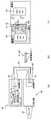
- Fig. 1 shows an overall view of the endoscope system of this example.
- the endoscope system of this example mainly includes a scope 10, a video processor 20, a high-intensity light source device 30 and the like, and may further include a monitor 6, an input device 7 (keyboard and the like), and the like.
- a video processor 20 and a high-intensity light source device 30 are connected to a scope (endoscope) 10. This connection configuration is the same as before and is not particularly shown.
- the auscultation light is output from the high-intensity light source device 30 to the scope 10, and the video signal from the scope 10 is input to the video processor 20. .
- the video processor 20 reads various information described later from the memory 12 of the scope 10.
- the scope 10 is an endoscope main body that is inserted into a body cavity of a patient.
- the scope 10 is a CCD 11 or an unillustrated ejection port (an ejection port that ejects the examination light supplied from the light source device 30) into the body cavity. It also has.
- the scope 10 is an endoscope that emits illumination light that irradiates an arbitrary subject in the body cavity (the above-mentioned examination light), and the endoscope is configured to capture an image of the subject illuminated by the illumination light. (CCD11) is provided.
- the scope 10 of this example further incorporates a memory 12 (ROM or the like) in which various information (CCD information, emission time information, lamp current information, etc.) related to the scope 10 is stored in advance.
- ROM read-only memory
- various information CCD information, emission time information, lamp current information, etc.
- the video processor 20 includes a control device 21 such as an FPGA (Field Programmable Gate Array), a video processing circuit 22, a nonvolatile memory 23, a buzzer 24, and the like, and further includes a plurality of connectors 1 to 4 as external interfaces. Yes.
- the connector 1 is connected to the monitor 6, the connector 2 is connected to an input device 7 such as a keyboard, the connector 3 is connected to an external server (not shown), and the connector 4 is connected to the high-intensity light source device 30. is doing.
- the FPGA Field Programmable Gate Array
- FPGA Field Programmable Gate Array
- An FPGA that can be rewritten in particular among programmable logic devices is called an FPGA. Sometimes it is defined to be called.
- the control device 21 receives, for example, an imaging signal (video signal) from the CCD 11 of the scope 10, generates a “video signal for monitor output” from the video signal, and passes it to the video processing circuit 22.
- the control device 21 further generates a photometric signal based on the input image pickup signal (video signal) from the CCD 11 and transfers the photometric signal to the light source device 30 via the connectors 4 and 5.
- This photometric signal indicates the brightness of the screen (intra-body cavity image) if briefly described, and is used for dimming control in the light source device 30.
- control device 21 includes a photometric signal generation function unit (not shown) that generates a photometric signal based on the image pickup signal from the CCD 11.
- the video processing circuit 22 causes the monitor 6 to display an image or the like in the body cavity of the patient based on the “video signal for monitor output”. Of course, this video signal is output to the monitor 6 via the connector 1.
- video processor information is stored in the nonvolatile memory 23.
- the video processor information is information indicating, for example, whether the video processor 20 is the frame sequential type or the simultaneous type.
- the scope 10 is always the same type as the video processor 20 for the frame sequential / simultaneous type. That is, if the video processor 20 is a frame sequential type, the scope 10 also corresponds to the frame sequential type, and if the video processor 20 is a simultaneous type, the scope 10 also corresponds to the simultaneous type.
- the non-volatile memory 23 of the video processor 20 stores an illumination method (frame sequential / simultaneous) suitable for the endoscope (scope 10).
- the control device 21 reads various information (the CCD information, the emission time information, the lamp current information, etc.) stored in the memory 12 of the scope 10 in an initial process such as startup, and further from the nonvolatile memory 23.
- the video processor information is read out, and the read out information is transferred to the high-intensity light source device 30.
- the control device 21 includes an illumination method reading function unit (not shown) that reads out the illumination method (frame sequential / simultaneous method) stored in the nonvolatile memory 23 as one of its processing functions. It can also be said that
- control device 21 generates the photometric signal and transfers it to the light source device 30 at any time during operation.
- the high-intensity light source device 30 is provided with the connector 5 shown in the figure.
- the connector 4 and the connector 5 are connected by an arbitrary communication line. Communication between the light source device 30 and the video processor 20 is performed using this communication line. Done through. Therefore, naturally, the control device 21 also transfers the various information to the high-intensity light source device 30 via this communication line.
- the light source device 30 and the video processor 20 operate in cooperation by transmitting / receiving data to / from each other via this communication line.
- the high-intensity light source device 30 includes a control device 31 such as an FPGA, a timing device (RTC & battery) 32, a light source control circuit 33, a nonvolatile memory 34, a program success / failure detection unit 35, a buzzer 36, and the like, and an external interface. And a connector 5 connected to the communication line.
- a control device 31 such as an FPGA, a timing device (RTC & battery) 32, a light source control circuit 33, a nonvolatile memory 34, a program success / failure detection unit 35, a buzzer 36, and the like, and an external interface.
- a connector 5 connected to the communication line.
- the light source control circuit 33 realizes RGB filter control, diaphragm blade control, and lamp current control operation according to control by the control device 31. Since the configuration of the light source control circuit 33 is an existing configuration disclosed in Patent Document 2 and the like, the light source control circuit 33 is not limited to an electronic circuit. A configuration for performing a physical operation such as a rotating color filter is also included, and will be briefly described below.
- the light source control circuit 33 is, for example, a light source lamp, a lamp control circuit, a motor, a motor control circuit, an aperture (aperture blade), an aperture control circuit, a rotating color filter, a motor movement control circuit, etc. disclosed in the above-mentioned Patent Document 2 It is what has.
- the rotating color filter is composed of three color transmission filters of R (red), G (green), and B (blue).
- R Light of any color of (red), G (green), and B (blue) is output to the scope 10 as the illustrated auscultation light, and irradiated from the distal end of the scope 10 into the body cavity.
- the RGB filter control basically controls the irradiation time of each color of R (red), G (green), and B (blue).
- the diaphragm blade control is to adjust the light amount (light intensity) of the examination light by adjusting and controlling the angle of the diaphragm blade by the diaphragm control circuit.
- the lamp current control the light amount of the examination light is adjusted by controlling the light emission amount of the light source lamp by the lamp control circuit.
- dimming is performed in conjunction with aperture blade control and lamp current control.
- the dimming control is performed based on the photometry signal and the like, but this is an existing technology and will not be particularly described.
- white light from the light source lamp can be output to the scope 10 as the illustrated auscultation light as it is by moving the rotating color filter and removing it from the optical axis.
- the connected video processor 20 when the connected video processor 20 (and the scope 10) is the “simultaneous type”, white light may be output to the scope 10 as the illumination light.
- the connected video processor 20 when the connected video processor 20 (and the scope 10) is the “plane sequential type”, the three colors R (red), G (green), and B (blue) are sequentially applied by the rotating color filter. What is necessary is just to output to the scope 10 as a reference light.
- the light source device 30 (for example, the main CPU 41) of this example automatically switches between the frame sequential type and the simultaneous type according to the type of the connected video processor 20 (and the scope 10) (illumination).
- the system can be switched).
- it has a function of switching between white light and RGB light as the examination light for the scope 10.
- the frame sequential / simultaneous switching control is automatically performed based on the video processor information.
- Such a function is called an RGB filter switching control function or an illumination system switching function.
- the initial process is executed by the main CPU 41, for example.
- the timing device 32 is composed of an RTC (real time clock) and a backup battery, and performs a timing operation.
- Arbitrary data (light source information, control information, log information, etc.) is stored in the nonvolatile memory 34.
- the control device 31 transmits the light source information, control information, log information, and the like to the video processor 20 at the time of initial processing such as startup or at an arbitrary time.
- the light source information is data indicating the current state of the light source (for example, white light or RGB light), and the control information and log information are, for example, various error information (battery voltage drop, operation dedicated CPU failure information, etc.).
- the error information is displayed on the monitor 6 or notified to an external server (not shown).
- control device 31 has a main CPU 41 and an operation-dedicated CPU 42.
- the computation-dedicated CPU 42 is a computation-dedicated CPU specialized for the dimming function.
- the calculation dedicated CPU 42 controls the light source control circuit 33 to realize the automatic light control function related to the scope 10. As described above, the calculation-dedicated CPU 42 performs dimming in conjunction with diaphragm blade control and lamp current control.
- the calculation-dedicated CPU 42 reads the various information (CCD information, lamp current information, etc.) read from the memory 12 of the scope 10 and transferred to the device 30 during the initial processing, and thereafter transferred as needed. Based on the photometric signal or the like, the automatic light control function according to the scope 10 is realized.
- the lamp current information is information on the range (upper limit value and lower limit value) of the lamp current value according to the characteristics of the scope 10 (the CCD 11). Therefore, it is possible to control the light amount within an appropriate range based on the lamp current information. By acquiring the lamp current information from the scope 10, an appropriate light amount can be provided for each CCD.
- the CCD information stored in the memory 12 is information indicating appropriate brightness (light quantity) according to the type (characteristic) of the CCD 11 of the scope 10.
- the initial value of the light amount is determined according to the CCD information. Thereafter, the light amount is adjusted and controlled based on feedback information (photometric signal or the like).
- the RGB filter control is further performed, which is executed by the main CPU 41.
- the emission time information is further stored in the memory 12 of the scope 10, and the emission time information is also sent from the video processor 20 to the light source device 30. Therefore, the main CPU 41 executes RGB filter control based on the emission time information.
- the RGB filter control itself is an existing control and will not be described in particular. However, it is possible to maintain a certain brightness for each CCD by acquiring and setting information related to the opening time (RGB emission time) from the scope 10. .
- the main CPU 41 is a central processing unit that controls the entire high-intensity light source device 30, and basically executes processes other than the dimming function of the arithmetic CPU 42. For example, communication processing with the video processor 20, the above RGB filter control (only in the case of the frame sequential type), various flag checks (abnormality check) described later, control processing of other configurations not shown, etc. Execute.
- the high-intensity light source device 30 is compatible with both the frame sequential type and the simultaneous type as described above, and the above-described RGB filter that emits light by either the plane sequential type or the simultaneous type. It also has a switching control function.
- the frame sequential type and the simultaneous type are disclosed in, for example, the above-described Reference Documents 1 and 2.
- the control device 31 communicates with the video processor 20 connected to its own device in the initial processing at the time of startup, and acquires the various information.
- the video processor information included in the various information indicates the type of the video processor 20 (frame sequential type or simultaneous type). Therefore, the control device 31 can select either the frame sequential type or the simultaneous type according to the video processor information. Control switching. That is, the type of emitted light (white light / RGB light) is automatically switched according to the type of the video processor 20 connected to the own apparatus.
- the present invention is not limited to this example.
- the type of emitted light can be switched according to an instruction from the video processor 20 (such as an instruction from the user).
- the video processor 20 is a simultaneous type
- the RGB filter control is further added as compared with the case of the simultaneous method. Therefore, it can be said that the operation common to both the simultaneous method and the frame sequential method is described.
- lamp current information, CCD information necessary for the dimming calculation is stored in advance in a memory 12 (ROM or the like) in the scope 10. It can be said that lamp current information and CCD information are stored corresponding to each CCD.
- the information stored in the memory 12 is read out by the video processor 20 and notified to the high-intensity light source device 30 in the initial processing or the like, so that the lamp current information, CCD information, etc. are also notified to the high-intensity light source device 30.
- the high-intensity light source device 30 can emit an appropriate amount of light according to the optical characteristics of the scope 10 (the CCD 11) as already described.
- the lamp current information, CCD, etc. can be obtained by operating the input device 7 (keyboard, etc.) connected to the video processor 20 by a user, for example. Information etc. can be set arbitrarily. Of course, the set lamp current information, CCD information, etc. are transferred from the video processor 20 to the high brightness light source device 30.
- the memory 12 (ROM or the like) in the scope 10 further stores emission time information of each color element of RGB in advance.
- the information stored in the memory 12 is read out by the video processor 20 and notified to the high-intensity light source device 30 in the initial processing or the like, so that the RGB emission time information is also notified to the high-intensity light source device 30. .
- the high-intensity light source device 30 can set the optimum emission time / irradiation time according to the optical characteristics of the scope 10 (the CCD 11).
- an optimum emission time / irradiation time (emission time / irradiation time for each color element of RGB) corresponding to the optical characteristics of the CCD 11 of the scope 10 is arbitrarily determined in advance. Is stored in the memory 12. In the following description, the extraction time / irradiation time is described as being unified with the irradiation time.
- a light source device for example, a configuration described in Patent Document 2
- the existing configuration is not particularly illustrated / explained here, but for example, the main CPU 41 or the like calculates the irradiation time for each color element of RGB read and transferred from the memory 12 of the scope 10 by the video processor 20.
- the main CPU 41 or the like calculates the irradiation time for each color element of RGB read and transferred from the memory 12 of the scope 10 by the video processor 20.
- the memory 12 of the scope 10 stores the irradiation time for each color element of RGB.
- the non-irradiation time may be stored.
- the non-irradiation time means a time zone other than the irradiation time within a predetermined period (one cycle), and thus the main CPU 41 can determine the irradiation time based on the non-irradiation time, for example.
- the structure which controls the irradiation time of each RGB color according to the set non-irradiation time may be sufficient as the said existing structure.
- the memory 12 of the scope 10 may store both irradiation time and non-irradiation time for each color element of RGB.
- the irradiation time or / and non-irradiation time for each of the RGB color elements is not limited to the above-described example (an example of reading and setting data stored in advance in the memory 12 of the scope 10).
- the input device 7 or the like may be arbitrarily input and set.
- HW (hardware) control and dimming control are the same as in the simultaneous type, and are not specifically described here.
- FIG. 2 is a diagram showing a detailed configuration of the control device 31 mainly of the high-intensity light source device 30.
- the control device 31 of the high-intensity light source device 30 has a main CPU 41 and an operation-dedicated CPU 42 which are also illustrated and described in FIG. Furthermore, the CPU has a calculation dedicated CPU status notification module 43, a main CPU status notification module 44, an HW control module 45, an RTC voltage drop flag 46, and an HW error flag 47.
- the calculation dedicated CPU state notification module 43 detects the normal / abnormal state of the calculation dedicated CPU 42.
- the main CPU state notification module 44 detects the normal / abnormal state of the main CPU 41. Both modules 43 and 44 hold, for example, a flag indicating a normal / abnormal state, and reflect the detection result of the normal / abnormal state in the flag. For example, when an abnormality is detected, the flag is turned on.
- the main CPU 41 / dedicated CPU 42 determines normality / abnormality by referring to this flag.
- the calculation dedicated CPU state notification module 43 substantially detects an abnormality in the calculation dedicated CPU 42 and notifies the main CPU 41 of the abnormality.
- the main CPU state notification module 44 substantially detects an abnormality in the main CPU 41 and notifies the arithmetic CPU 42 of the abnormality.
- the RTC voltage drop flag 46 is a flag that indicates a drop in the backup battery in the time measuring device 32.
- the time measuring device 32 has a function of detecting a decrease in the backup battery and a function of turning on the RTC voltage decrease flag 46 when the decrease in the backup battery is detected.
- the main CPU 41 can recognize the decrease in the backup battery by referring to the RTC voltage decrease flag 46.
- the HW error flag 47 is a flag indicating an error of the HW control module 45.
- the HW control module 45 has a function of detecting an abnormality of itself or hardware (motor, lamp, etc.) and a function of turning on the HW error flag 47 when an abnormality is detected.
- the main CPU 41 or the like can recognize the occurrence of an abnormality related to the HW control module 45 by referring to the HW error flag 47.
- each module and the CPUs 41 and 42 shift the apparatus 30 to a safe state (for example, in the case of detecting a motor failure, it is dangerous to operate the motor. For example, switching to a mode that does not move the lamp, or turning off the lamp when a lamp abnormality is detected).
- the HW error flag 47 may be provided with a flag corresponding to various failures (motor failure, lamp abnormality, etc.) as well as one flag.
- a configuration for detecting an error of the HW control module 45 can be provided, and error processing can be performed after the device is in a safe state in the event of an error.
- the main CPU 41 or the like when it is detected that the backup battery is low, for example, the main CPU 41 or the like notifies the external server (not shown) via the video processor 20 of “Backup battery low”. As a result, it is possible to grasp in advance the stop of the timing operation of the RTC, thereby preventing the battery from running out.
- the flag is set until the operation becomes stable, such as at the time of starting the device, it can be controlled not to perform unstable operation at the time of starting.
- the HW control module 45 is an existing configuration that controls a motor, a lamp, and the like, and is not particularly described here. However, as shown in FIG. 2, control signals such as motors and lamps are output from the HW control module 45 to the light source control circuit 33, but at least the lamp current value is controlled by the calculation-dedicated CPU 42. By doing so, the brightness of the lamp is controlled. Thus, it can be said that the calculation-dedicated CPU 42 performs not only aperture blade control but also control of the lamp current value (lamp brightness).
- the main CPU 41 when an abnormality occurs in the calculation-dedicated CPU 42, the main CPU 41 supplements the dimming calculation function and continues the automatic dimming function. However, since the main CPU 41 also controls the entire high-intensity light source device 30, if the automatic dimming function executed by the calculation-dedicated CPU 42 is continued as it is, the processing load becomes very large. In some cases, the processing load on the main CPU 41 is too large, and an abnormality may occur in the operation of the main CPU 41.
- the main CPU 41 does not continue the automatic dimming function that was executed by the calculation-dedicated CPU 42 as it is, but it is a so-called “simplified automatic dimming function” (hereinafter referred to as a simple dimming function). Execute).
- this simple dimming function for example, the lamp current control is stopped and the lamp current value is fixed and only the diaphragm blade control is performed, the FB (feedback) control period is extended, A method of roughening the dimming gradation can be considered.
- the present invention is not limited to these examples, and a simple dimming function can be realized by executing some simple arithmetic algorithm.
- the method of lengthening the FB (feedback) control period is, for example, to change the control for every frame to control for every 2 frames, for example every 3 frames, or the like.
- the existing dimming control is to control the endoscope screen for each frame (for each photometric signal for one frame).
- the processing burden can be reduced.
- the calculation cycle for the dimming is performed by setting the calculation cycle by the main CPU 41 to be longer than the calculation cycle (one frame in the above example) performed by the calculation dedicated CPU 42.
- the method of roughening the light control gradation is a method of roughening the control step of the diaphragm blade (for example, changing the control of the angle of 2 degrees to the control of 5 degrees).
- the dimming control is performed at 5 degrees.
- the main CPU 41 continues the automatic dimming function performed by the calculation-dedicated CPU 42 as it is, and executes overall control of the high-intensity light source device 30 with a simplified algorithm (hereinafter, simplified overall control). ). That is, the original processing function of the main CPU 41 is limited, and a specific gravity is placed on the arithmetic processing of the automatic light control function.
- the main CPU 41 may perform a return operation such as giving a reset signal to the operation-dedicated CPU 42 in parallel with executing the processing according to the first or second method. Further, it may be stored in the nonvolatile memory 34 as a log that the computation dedicated CPU 42 is in an error state.
- FIG. 3 shows a specific example of the first method.
- FIG. 3 is a process flowchart (part 1) showing the operation of the control device 31.
- the main CPU 41 and the calculation-dedicated CPU 42 execute predetermined activation processes (initial processes), respectively, and are normally activated here (step S11). , S21).
- the main CPU 41 and the calculation dedicated CPU 42 repeatedly execute predetermined processes.
- the main CPU 41 controls the entire high-intensity light source device 30 as described above, and also performs RGB filter control in the case of the frame sequential type as described above (step S12).
- the overall control process includes a process of periodically checking whether or not the calculation dedicated CPU 42 is normal (step S13). This refers to the flag of the calculation dedicated CPU state notification module 43, and when the flag is set (when the flag is ON), it is determined as abnormal (step S13, NO), and when the flag is not set (flag) (OFF) is determined as normal (step S13, YES). If it is determined to be normal (step S13, YES), the process returns to step S12, and the above-described normal processing (various overall control (including RGB filter control in the case of frame sequential type)) is continued.
- the calculation-dedicated CPU 42 performs calculation processing (aperture blade, lamp current interlocking control) of the automatic light control function as described above (step S22).
- the RGB filter control, diaphragm blade control, and lamp current control are performed by the main CPU 41 or the calculation-dedicated CPU 42 outputting an arbitrary control signal to the light source control circuit 33, whereby the RGB filter control by the light source control circuit 33 is performed. And diaphragm blade control and lamp current control.
- step S23 If any abnormality occurs in the computation dedicated CPU 42 at any time (such as when a failure occurs) (step S23), the computation dedicated CPU 42 stops, and the computation dedicated CPU state notification module 43 detects this abnormality. The self flag is set (step S24).
- step S13 when the main CPU 41 subsequently performs the process of step S13, it is determined that there is an abnormality (step S13, NO), and the process proceeds to steps S14 to S17. If the processing in steps S12 and S13 is the normal mode processing of the main CPU 41, it can be said that the processing in steps S14 to S17 is the special mode processing of the main CPU 41. That is, the main CPU 41 can be considered to be in the normal mode until step S13 becomes NO, and shift to the special mode when step S13 becomes YES.
- the processing in step S14 is substantially the same as the processing in step S12 described above, and includes various overall controls (including RGB filter control in the case of the frame sequential type). That is, various overall controls that are the original control of the main CPU 41 are continued as they are even after the operation-dedicated CPU 42 has failed.
- step S14 the processes of steps S15, S16, and S17 are executed.
- step S15 the simple arithmetic algorithm that realizes the above-described simple dimming function is activated (step S15).
- step S16 the simple light control function of steps S16 and S17 is realized. That is, the lamp current value is a fixed value (step S16), and only diaphragm blade control is executed (step S17).
- step S17 the processing load on the main CPU 41 is reduced by not performing the control regarding the lamp current value substantially.
- step S17 control for extending the above-described FB (feedback) control period or control for roughening the dimming gradation may be performed. In this way, the processing load on the main CPU 41 is further reduced.
- the processing load increases as compared with the normal mode, but an increase in the processing load can be suppressed.
- the lamp current value (fixed value) is included in, for example, the program of the simple calculation algorithm.
- only the diaphragm blade control is performed without performing the lamp current control.
- the present invention is not limited to this example, and may be reversed. That is, only the lamp current control may be executed without performing the diaphragm blade control (for example, fixing the diaphragm blade angle to a predetermined angle).
- FIG. 4 shows a specific example of the second method.
- the main CPU 41 after the failure of the operation-dedicated CPU 42 executes the same automatic dimming function as that of the operation-dedicated CPU 42 and simplifies the overall control.
- FIG. 4 is a process flowchart (part 2) illustrating the operation of the control device 31. 4, processing steps that are substantially the same as the processing steps shown in FIG. 3 are given the same reference numerals, and descriptions thereof are omitted or simplified.
- step S21 when the operation-dedicated CPU 42 is normally started by turning on the power (step S21), it performs dimming control (aperture blade control and lamp current control) (step S22). If any abnormality (failure or the like) occurs in the calculation dedicated CPU 42 at any time (step S23), the calculation dedicated CPU 42 stops, and the calculation dedicated CPU state notification module 43 detects this abnormality and sets a flag (step S23). S24).
- step S11 When the main CPU 41 starts up normally when the power is turned on (step S11), the main CPU 41 executes the above-described overall control (including RGB filter control in the case of the frame sequential type) (step S12). The presence or absence is checked (step S13). Then, when the abnormality of the calculation dedicated CPU 42 is detected by the flag ON (step S13, NO), the process proceeds to steps S14 to S17 in FIG. 3, but here the processes of steps S31, S32, and S33 shown in FIG. 4 are performed. Execute.
- the main CPU 41 may be considered to be in the normal mode until step S13 becomes NO, and shift to the special mode when step S13 becomes YES. it can. That is, the processing of the calculation dedicated CPU 42 is the same as that in FIG.
- the processing of the main CPU 41 is the same as the processing in the normal mode as in FIG. 3, but the processing in the special mode is different from that in FIG.
- the main CPU 41 executes simplified overall control (step S31). This simplifies and executes the overall control function of the light source device in step S12. For example, switching to an observation mode (a mode using special light; see Japanese Patent Laid-Open No. 2009-142654, etc.) is prohibited.
- the polling time is lengthened (the main CPU 41 performs processing for referring to the flags in the modules 43 and 44 and various flags such as the flags 46 and 47 at regular intervals.
- the overall control is simplified by increasing the time interval).
- the main CPU 41 also executes the processes of steps S32 and S33 in parallel with the process of step S31. That is, a predetermined calculation algorithm is activated (step S32), and the dimming control (aperture blade control and lamp current control) is executed by executing this calculation algorithm (step S33).
- step S33 may be the same as the process in step S22.
- the calculation-dedicated CPU 42 also retains the predetermined calculation algorithm in step S32, and by starting this calculation algorithm during the processing in step S21, the above-described step It can be said that the process of S22 is performed.
- the main CPU 41 substantially takes over the dimming control (aperture blade control and lamp current control) of the computation dedicated CPU 42 as it is.
- the overall control of the light source device is executed in a simplified manner to reduce the processing load. As described above, the processing load increases compared to the normal mode, and the reduction of the processing load means that the increase of the processing load is suppressed.
- both the main CPU 41 and the operation-dedicated CPU 42 can perform dimming control (including simple dimming control). That is, the main CPU 41 or the calculation-dedicated CPU 42 can generate a control signal for dimming control (referred to as a dimming signal) based on the photometric signal and output it to the light source control circuit 33. Therefore, for example, as shown in FIG. 2, the signal line 51 for outputting a dimming signal from the main CPU 41 to the light source control circuit 33 and the dimming signal from the arithmetic CPU 42 to the light source control circuit 33 are output. A signal line 52 is provided for this purpose.
- a dimming signal is output from the calculation-dedicated CPU 42 to the light source control circuit 33.
- a dimming signal is output from the main CPU 41 to the light source control circuit 33. Since the light source control circuit 33 does not know the mode switching between “normal mode and special mode”, a countermeasure is required.
- This countermeasure method may be various, but here are two examples.
- a selector 33a is provided in the light source control circuit 33, and the two signal lines 51 and 52 are connected to the input side of the selector 33a.
- the selector 33a selects / outputs one of these two signal lines 51 and 52.
- a function (not shown) for detecting the presence / absence of signals on these two signal lines 51 and 52 is provided on the light source control circuit 33 side, and the signal line of “signal present” is selected by the selector 33a.
- the operation dedicated CPU 42 when the operation dedicated CPU 42 fails, it basically stops as described above, but does not stop for some reason and does not stop for any signal on the signal line 52 (because it has failed, it becomes a meaningless signal). There is a possibility of continuing to output.
- the main CPU 41 notifies the light source control circuit 33 of the calculation dedicated CPU state notification.
- FIG. 5 is a process flowchart (part 3) illustrating the operation of the control device 31.
- processing steps that are substantially the same as the processing steps shown in FIG. 3 are given the same reference numerals, and descriptions thereof are omitted or simplified.
- the processing until any abnormality occurs in the computation-dedicated CPU 42 is substantially the same as the processing in steps S11 to S13 and steps S21 to S24 in FIG. 3, and therefore the same step numbers are given. The description is omitted.
- the main CPU 41 notifies the light source control circuit 33 of the state of the operation-dedicated CPU (occurrence of abnormality) as shown in FIG. S41).
- the light source control circuit 33 operates using the dimming signal from the main CPU 41 thereafter.
- the selector 33a is switched and the dimming signal from the main CPU 41 is selected and output in the selector 33a.
- the selector 33a is used in both the first countermeasure example and the second countermeasure example, but the switching control is determined on the light source control circuit 33 side in the first countermeasure example, but the second countermeasure is taken.
- it may be considered to be executed in response to an instruction (notification) from the main CPU 41.
- it is not limited to such an example.
- step S42 the process in the special mode by the main CPU 41 is started (step S42).
- This may be either the first method or the second method. That is, the processing of steps S14, S15, S16, and S17 shown in FIG. 3 may be started, or the processing of steps S31, S32, and S33 shown in FIG. 4 may be started. .
- the selector 33a controls the dimming that is calculated and output by the calculation dedicated CPU 42 when the calculation dedicated CPU state notification module 43 determines that the calculation dedicated CPU 42 is normal.
- a signal (referred to as a first dimming signal) is selected and output.
- the selector 33a is output by the main CPU 41 when the calculation dedicated CPU state notification module 43 determines that the calculation dedicated CPU 42 is abnormal.
- a dimming signal (referred to as a second dimming signal) is selected and output.
- the light source control circuit 33 which is actually configured to perform dimming of the examination light based on the dimming signal from the CPU, is a dimming signal selected by the selector 33a (the first dimming signal, Either one of the second dimming signals) Dimming of the examination light is performed.
- the illumination light is dimmed based on the second dimming signal.
- This second dimming signal is calculated and output by the main CPU 41 as described above.
- the main CPU 41 can supplement the dimming calculation function and continue the automatic dimming function while suppressing an increase in processing load on the main CPU 41.
- the main CPU 41 can supplement the dimming calculation function and continue the automatic dimming function.
- the worst case of interrupting the procedure during the procedure is avoided.
- the programs of the CPUs 41 and 42 are held in a duplicated manner. Things are also possible.
- an arbitrary program (referred to as a first program) to be executed by the arithmetic CPU 42 is stored in an arbitrary area of the nonvolatile memory 34 in advance, and a second program is stored in the other area. deep.
- the second program may be the same as the first program, but is not limited to this example.
- the second program can be executed by turning on the power again, for example.
- any program to be executed by the main CPU 41 is held in the nonvolatile memory 34 in a duplicated manner (referred to as a third program and a fourth program).
- the fourth program can be executed by turning on the power again.
- the first program and the second program differ only in the storage area and may be the same program or may be slightly different programs (for example, a normal version program and a simplified processing version program ( Etc.) which only perform the above-mentioned diaphragm blade control)).
- Etc. simplified processing version program
- the plurality of areas of the nonvolatile memory 34 are assumed to be area 1, area 2, area 3, and area 4, for example, the first program is stored in area 1, and area 2 is stored in area 2. The second program is stored, the third program is stored in area 3, the fourth program is stored in area 4, and the like.
- each of the CPUs 41 and 42 reads the program executed by itself from the nonvolatile memory 34 when the endoscope system is activated, for example, and then executes the program. .
- the calculation-dedicated CPU 42 reads the first program from area 1 and the main CPU 41 reads the third program from area 3 at the time of activation.
- the program success / failure detection unit 35 detects the success or failure of reading these programs.
- This detection method can be realized by an existing technique, and uses, for example, a data error detection method when transmitting / receiving data such as CRC (Cyclic Redundancy Check) or checksum in communication.
- CRC Cyclic Redundancy Check
- the program success / failure detection unit 35 checks the program read from the volatile memory 34 by the CPU 41 or the CPU 42 based on the CRC, checksum, etc., and detects whether or not this program has an abnormality. If there is an abnormality in the program, it is determined that the program has failed to be read.
- the CPUs 41 and 42 read the other duplicated program. For example, when the program success / failure detection unit 35 detects that the reading of the first program has failed, the calculation-dedicated CPU 42 reads the second program from the area 2. Similarly, for example, when the program success / failure detection unit 35 detects that the reading of the third program has failed, the main CPU 41 reads the fourth program from the area 4.
- Such a program read control function is included in the control device 31, but is not necessarily included in each of the CPUs 41 and 42 as in the above example, and may be realized by another configuration (not illustrated) included in the control device 31. Good.
- the video processor 20 and the high-intensity light source device 30 When the video processor 20 and the high-intensity light source device 30 are activated, the video processor 20 and the high-intensity light source device 30 start a cooperative operation via a communication cable connected to the connector 4 and the connector 5. At that time, since communication is not possible unless the communication cable is normally connected, it is desirable to have a configuration for detecting that the communication cable is normally connected.
- FIG. 6A schematically shows the scope 10, the video processor 20, and the high-intensity light source device 30, and more specifically shows the configuration related to the connection between the video processor 20 and the high-intensity light source device 30.
- a harness 80 is a communication cable for connecting the video processor 20 and the high-intensity light source device 30.
- one end is connected to the connector 4 of the video processor 20, and the other end is connected. It is connected to the connector 5 of the high brightness light source device 30.
- the illustrated connection board 62 corresponds to the connector 4, and the connection board 71 corresponds to the connector 5.
- the control board 61 corresponds to the control device 21.
- the harness 80 includes a cable portion 83 illustrated, a connector portion 81 and a connector portion 82 at both ends of the cable portion 83.
- the connector part 81 is connected to the connection board 71, and the connector part 82 is connected to the connection board 62.
- both the connector part 81 and the connector part 82 are configured to have connection detection pins at both ends as shown in FIG.
- FIG. 6A shows only the lines related to the connection detection pins, and omits the lines related to other pins (there are seven other pins in the example of FIG. 6B). The description is also omitted.
- connection board 71 (connector 5) of the high-intensity light source device 30 that connects the two connection detection pins of the connector portion 81 is grounded.
- connection board 62 (connector 4) of the video processor 20
- the wiring patterns 63 and 64 shown in the figure are connected to the portion where the two connection detection pins of the connector portion 82 are connected. Is connected to a power source (not shown) via resistors R1 and R2 shown on the control board 61.
- the FPGA 61a on the control board 61 monitors the voltage on the wiring patterns 63 and 64, so that the harness 80 is connected or not (normally connected between the video processor 20 and the high-intensity light source device 30). Or not).
- the configuration itself for detecting the presence or absence of such a connection is an existing technology.
- a total of two connection detection pins are provided at both ends of the connector.
- the communication cable is connected to both the connector 4 of the video processor 20 and the connector 5 of the high-intensity light source device 30, but since it is not connected properly, one of the connectors 4 and 5 is connected.
- a state where they are connected halfway for example, a state where they are not normally connected such as half-insertion
- connection detection pin Even when two connection detection pins are provided, the configuration is not limited to two at one end as described above. For example, when two are provided at one end of the connector, these two Even when the pins are connected, the pins on the other end side of the connector may not be connected properly.
- connection detection pin at each end of the connector as shown in FIG. 6B
- FIG. 6 (c) two substrates A and B are conventionally connected to each other by inter-board connectors 91 and 92 provided on the respective substrates A and B.
- inter-board connectors 91 and 92 provided on the respective substrates A and B.
- 6C shows a state in which the board-to-board connectors 91 and 92 are already connected, the board-to-board connector 91 is provided on the board A, and the board-to-board connector 92 is provided on the board B.
- control device 21 and the control device 31 may be configured as shown in FIG.
- the illustrated FPGA (CPU) 93 on the board A corresponds to the main CPU 41
- the FPGA (CPU) 94 on the board B is dedicated to the calculation. It can also be considered to correspond to the CPU 42.
- the board-to-board connectors 91 and 92 have a total of four connection detection pins, two at each end.
- the configuration related to each of the four pins is substantially the same as that shown in FIGS. 6A and 6B.
- one of the substrates A and B is grounded and the other is connected to the other.
- the pin (M) is a connection detection pin.
- the pin (1) of the board-to-board connector 91 and the pin (1) of the board-to-board connector 92 are connected (the same applies to the other pins, and the pins having the same number are connected to each other).
- the uppermost pin in the drawing of the inter-board connectors 91 and 92 is the pin (1) and the lowermost pin is the pin (M).
- the pin (1) of the board-to-board connector 91 is connected to GND
- the pin (1) of the board-to-board connector 92 is connected to the power supply Vcc
- the FPGA (CPU on the board B) ) 94 can detect whether or not the pin (1) is connected.
- the pin (M-1) of the board-to-board connector 91 is connected to GND
- the pin (M-1) of the board-to-board connector 92 is connected to the power source Vcc and on the board B.
- the FPGA (CPU) 94 is connected. Thereby, the FPGA (CPU) 94 can detect whether or not the pin (M-1) is connected.
- connection detection pins a configuration including a total of four connection detection pins, two at each end.
- the configuration is not limited to this example, and a configuration including a total of two connection detection pins, one at each end, may be used.
- only one of the FPGAs (CPUs) 93 and 94 determines whether or not the inter-board connector 91 and the inter-board connector 92 are normally connected.
- pin (2) and the pin (M-1) cannot be said to be pins at both ends, strictly speaking, but can be said to be almost pins at both ends, and the effect does not change so much.
- These pins (2) and (M-1) are also defined as pins at both ends.
- a buzzer or monitor display is used to notify or limit the control (for example, minimize the amount of light). For example, regarding the notification, in the case of the video processor 20, the control device 21 sounds the buzzer 24 or displays some error message on the monitor 6. In the case of the high brightness light source device 30, the control device 31 sounds the buzzer 36.
- connection detection is also performed in the same process for inter-board connection in the apparatus as shown in FIG. 6C. You can also
- the control devices 21 and 31 read the set values from the nonvolatile memories 23 and 34 and start the activation process (this is an existing general operation). Therefore, the setting value and the activation process are not particularly described).
- a user or the like inputs an arbitrary comment from the input device 7 (keyboard or the like) in advance, and this comment is stored in the nonvolatile memory 23. Then, the control device 21 reads not only the set value but also the comment from the nonvolatile memory 23 during the activation process. Then, the control device 21 displays the read comment in the endoscope screen of the monitor 6 (its comment display column or the like).
- a heat-shrinkable tube that is independent of the shield processing unit is used.
- a paired wire and an electric wire ground wire 107 may be brought into close contact with each other to improve the EMI performance. This feature will be described with reference to FIG.
- FIGS. 7A to 7C show the cable 100 in which the pair wire 105 is covered with the shield 103 and the covering 104.
- FIG. It is necessary to provide connectors for connecting to the connectors 1 to 5 and the like at both ends of the cable 100, and it is necessary to connect the pair wire 105, the ground wire 107, etc. (soldering etc.) to this connector.
- the ground wire 107 is an electric wire connected to the shield 103.
- FIG. 7B is a perspective view of the inside of the covering 104 and the inside of the heat shrinkable tube 101.
- the shield 103 and the covering 104 are removed as described above, as in the cable 100A and the cable 100B shown in FIGS. 7A and 7C.
- the paired wire 105 and the ground wire 107 are covered with a heat-shrinkable tube (the heat-shrinkable tube 102 and the heat-shrinkable tube 106 shown in the figure) that is different from the heat-shrinkable tube 101 of the “shielding unit”.
- the heat-shrinkable tubes (101, 102, 106) shrink when heated, and FIG. 7 (a) and FIG. The state after adding is shown.
- the heat-shrinkable tubes 102 and 106 shrink in this way, the heat-shrinkable tubes 102 and 106 cover the paired wires 105 and the like so as to be in close contact with the paired wires 105 and the like as shown in the figure. (Earth wire) can be brought into close contact to improve the EMI performance.
- FIG. 7A The difference between FIG. 7A and FIG. 7C is that the heat-shrinkable tube 102 in FIG. 7A is a relatively long single tube, but the heat-shrinkable tube 106 in FIG. Is a relatively short plurality (three in this example) of tubes.
- the heat-shrinkable tube processing can be devised to ensure flexibility and workability while ensuring EMI performance.
- the calculation dedicated CPU is related to the light source device provided with the main CPU and the calculation dedicated CPU dedicated to the light amount adjustment function (dimming function) to the endoscope. If a failure occurs, the main CPU can perform dimming while suppressing an increase in processing load instead. As a result, it is possible to avoid a situation in which the inspection cannot be continued even when the operation-dedicated CPU breaks down during some inspection.
Landscapes
- Health & Medical Sciences (AREA)
- Life Sciences & Earth Sciences (AREA)
- Surgery (AREA)
- Physics & Mathematics (AREA)
- Engineering & Computer Science (AREA)
- Optics & Photonics (AREA)
- Biomedical Technology (AREA)
- Veterinary Medicine (AREA)
- Biophysics (AREA)
- Pathology (AREA)
- Radiology & Medical Imaging (AREA)
- Nuclear Medicine, Radiotherapy & Molecular Imaging (AREA)
- Public Health (AREA)
- Heart & Thoracic Surgery (AREA)
- Medical Informatics (AREA)
- Molecular Biology (AREA)
- Animal Behavior & Ethology (AREA)
- General Health & Medical Sciences (AREA)
- Signal Processing (AREA)
- Multimedia (AREA)
- Astronomy & Astrophysics (AREA)
- General Physics & Mathematics (AREA)
- Endoscopes (AREA)
- Instruments For Viewing The Inside Of Hollow Bodies (AREA)
- Closed-Circuit Television Systems (AREA)
Abstract
L'invention porte sur un système d'endoscope dans lequel, normalement, une unité centrale de traitement (CPU) principale (41) commande le système en entier tandis qu'une unité centrale de traitement (CPU) de calcul dédiée (42) commande la modulation de la lumière d'examen fournie à un champ d'application (10). Si l'unité centrale de traitement (CPU) de calcul dédiée (42) fonctionne mal, l'unité centrale de traitement (CPU) principale (41) commande la modulation de lumière mentionnée ci-dessus d'une manière simplifiée tout en continuant à commander le système en entier. Ladite commande de modulation de lumière simplifiée comprend, par exemple, la commande seulement de lames d'ouverture sans commander le courant de lampe.
Priority Applications (4)
| Application Number | Priority Date | Filing Date | Title |
|---|---|---|---|
| JP2012520402A JP5090579B2 (ja) | 2010-07-14 | 2011-06-24 | 内視鏡システム、その光源装置 |
| CN201180021955.XA CN102869297B (zh) | 2010-07-14 | 2011-06-24 | 内窥镜系统及其光源装置 |
| EP11806614.1A EP2554106B1 (fr) | 2010-07-14 | 2011-06-24 | Systeme d'endoscope et appareil de source de lumiere correspondante |
| US13/429,477 US8477183B2 (en) | 2010-07-14 | 2012-03-26 | Endoscope system and light source device therefor |
Applications Claiming Priority (2)
| Application Number | Priority Date | Filing Date | Title |
|---|---|---|---|
| JP2010160117 | 2010-07-14 | ||
| JP2010-160117 | 2010-07-14 |
Related Child Applications (1)
| Application Number | Title | Priority Date | Filing Date |
|---|---|---|---|
| US13/429,477 Continuation US8477183B2 (en) | 2010-07-14 | 2012-03-26 | Endoscope system and light source device therefor |
Publications (1)
| Publication Number | Publication Date |
|---|---|
| WO2012008283A1 true WO2012008283A1 (fr) | 2012-01-19 |
Family
ID=45469293
Family Applications (1)
| Application Number | Title | Priority Date | Filing Date |
|---|---|---|---|
| PCT/JP2011/064533 Ceased WO2012008283A1 (fr) | 2010-07-14 | 2011-06-24 | Système d'endoscope et appareil de source de lumière correspondante |
Country Status (5)
| Country | Link |
|---|---|
| US (1) | US8477183B2 (fr) |
| EP (1) | EP2554106B1 (fr) |
| JP (1) | JP5090579B2 (fr) |
| CN (1) | CN102869297B (fr) |
| WO (1) | WO2012008283A1 (fr) |
Families Citing this family (4)
| Publication number | Priority date | Publication date | Assignee | Title |
|---|---|---|---|---|
| JP2014014656A (ja) * | 2012-06-15 | 2014-01-30 | Canon Inc | 内視鏡システム |
| KR20140102521A (ko) | 2013-02-14 | 2014-08-22 | 삼성전자주식회사 | 내시경 장치 및 그 제어 방법 |
| JP6168879B2 (ja) * | 2013-06-27 | 2017-07-26 | オリンパス株式会社 | 内視鏡装置、内視鏡装置の作動方法及びプログラム |
| JP6177436B2 (ja) * | 2014-07-28 | 2017-08-09 | オリンパス株式会社 | 内視鏡システム及び画像処理装置 |
Citations (10)
| Publication number | Priority date | Publication date | Assignee | Title |
|---|---|---|---|---|
| JPS6076888A (ja) | 1983-10-03 | 1985-05-01 | Olympus Optical Co Ltd | 撮像用自動調光装置 |
| JPS60232523A (ja) | 1984-05-02 | 1985-11-19 | Olympus Optical Co Ltd | 内視鏡用光源装置 |
| JPS6182731A (ja) | 1984-09-28 | 1986-04-26 | オリンパス光学工業株式会社 | 内視鏡装置 |
| JPS6476829A (en) * | 1988-09-01 | 1989-03-22 | Olympus Optical Co | Endoscopic apparatus |
| JPH0321219A (ja) | 1989-03-16 | 1991-01-30 | Olympus Optical Co Ltd | 内視鏡用光源装置 |
| JPH05277065A (ja) * | 1992-02-07 | 1993-10-26 | Olympus Optical Co Ltd | 電子内視鏡装置 |
| JPH07171095A (ja) * | 1993-11-29 | 1995-07-11 | Olympus Optical Co Ltd | 内視鏡装置 |
| JPH09164115A (ja) * | 1995-12-15 | 1997-06-24 | Fuji Photo Optical Co Ltd | 面順次式内視鏡用光源装置 |
| JP2005342147A (ja) * | 2004-06-02 | 2005-12-15 | Olympus Corp | 電子内視鏡装置 |
| JP2009142654A (ja) | 2008-12-08 | 2009-07-02 | Olympus Corp | 内視鏡装置 |
Family Cites Families (13)
| Publication number | Priority date | Publication date | Assignee | Title |
|---|---|---|---|---|
| JPH01257911A (ja) * | 1988-04-08 | 1989-10-16 | Olympus Optical Co Ltd | 内視鏡用光源装置 |
| US5068719A (en) * | 1989-06-07 | 1991-11-26 | Olympus Optical Co., Ltd. | Endoscope photometric apparatus |
| US5134469A (en) * | 1989-11-16 | 1992-07-28 | Olympus Optical Co., Ltd. | Endoscope light source apparatus with detachable flash unit |
| US5868666A (en) | 1993-11-26 | 1999-02-09 | Olympus Optical Co., Ltd. | Endoscope apparatus using programmable integrated circuit to constitute internal structure thereof |
| JP4397993B2 (ja) * | 1999-03-24 | 2010-01-13 | オリンパス株式会社 | 顕微鏡写真撮影装置 |
| US9149175B2 (en) * | 2001-07-26 | 2015-10-06 | Given Imaging Ltd. | Apparatus and method for light control in an in-vivo imaging device |
| JP3880351B2 (ja) * | 2001-09-21 | 2007-02-14 | フジノン株式会社 | 遮光板を駆動する電子内視鏡装置 |
| JP2003135393A (ja) * | 2001-10-30 | 2003-05-13 | Olympus Optical Co Ltd | 内視鏡システムの自動調整方法 |
| US7248281B2 (en) * | 2002-07-16 | 2007-07-24 | Fujinon Corporation | Electronic endoscope apparatus which superimposes signals on power supply |
| US20070123751A1 (en) * | 2005-11-29 | 2007-05-31 | Pentax Corporation | Endoscope with brightness adjustment function |
| JP4315952B2 (ja) * | 2005-12-28 | 2009-08-19 | オリンパスメディカルシステムズ株式会社 | 光源装置、及び内視鏡システム |
| JP2008048905A (ja) * | 2006-08-24 | 2008-03-06 | Olympus Medical Systems Corp | 内視鏡装置 |
| JP2009072213A (ja) * | 2007-09-18 | 2009-04-09 | Hoya Corp | 内視鏡光源ユニットおよび内視鏡システム |
-
2011
- 2011-06-24 EP EP11806614.1A patent/EP2554106B1/fr not_active Not-in-force
- 2011-06-24 JP JP2012520402A patent/JP5090579B2/ja not_active Expired - Fee Related
- 2011-06-24 WO PCT/JP2011/064533 patent/WO2012008283A1/fr not_active Ceased
- 2011-06-24 CN CN201180021955.XA patent/CN102869297B/zh active Active
-
2012
- 2012-03-26 US US13/429,477 patent/US8477183B2/en not_active Expired - Fee Related
Patent Citations (10)
| Publication number | Priority date | Publication date | Assignee | Title |
|---|---|---|---|---|
| JPS6076888A (ja) | 1983-10-03 | 1985-05-01 | Olympus Optical Co Ltd | 撮像用自動調光装置 |
| JPS60232523A (ja) | 1984-05-02 | 1985-11-19 | Olympus Optical Co Ltd | 内視鏡用光源装置 |
| JPS6182731A (ja) | 1984-09-28 | 1986-04-26 | オリンパス光学工業株式会社 | 内視鏡装置 |
| JPS6476829A (en) * | 1988-09-01 | 1989-03-22 | Olympus Optical Co | Endoscopic apparatus |
| JPH0321219A (ja) | 1989-03-16 | 1991-01-30 | Olympus Optical Co Ltd | 内視鏡用光源装置 |
| JPH05277065A (ja) * | 1992-02-07 | 1993-10-26 | Olympus Optical Co Ltd | 電子内視鏡装置 |
| JPH07171095A (ja) * | 1993-11-29 | 1995-07-11 | Olympus Optical Co Ltd | 内視鏡装置 |
| JPH09164115A (ja) * | 1995-12-15 | 1997-06-24 | Fuji Photo Optical Co Ltd | 面順次式内視鏡用光源装置 |
| JP2005342147A (ja) * | 2004-06-02 | 2005-12-15 | Olympus Corp | 電子内視鏡装置 |
| JP2009142654A (ja) | 2008-12-08 | 2009-07-02 | Olympus Corp | 内視鏡装置 |
Non-Patent Citations (1)
| Title |
|---|
| See also references of EP2554106A4 |
Also Published As
| Publication number | Publication date |
|---|---|
| US8477183B2 (en) | 2013-07-02 |
| JP5090579B2 (ja) | 2012-12-05 |
| CN102869297B (zh) | 2015-04-29 |
| EP2554106B1 (fr) | 2014-03-26 |
| US20120242812A1 (en) | 2012-09-27 |
| EP2554106A1 (fr) | 2013-02-06 |
| EP2554106A4 (fr) | 2013-04-10 |
| CN102869297A (zh) | 2013-01-09 |
| JPWO2012008283A1 (ja) | 2013-09-09 |
Similar Documents
| Publication | Publication Date | Title |
|---|---|---|
| CN103079454B (zh) | 摄像装置 | |
| US8885033B2 (en) | Endoscope system | |
| US7766818B2 (en) | Electronic endoscope system | |
| US10524646B2 (en) | Light source apparatus | |
| JP5090579B2 (ja) | 内視鏡システム、その光源装置 | |
| JP2009072247A (ja) | 観察画像形成装置 | |
| CN106455959B (zh) | 摄像系统 | |
| US11783942B2 (en) | Method and apparatus for medical devices under regulatory control | |
| WO2017221738A1 (fr) | Dispositif de traitement d'image | |
| JP2015160098A (ja) | 内視鏡システム | |
| JPWO2013121616A1 (ja) | 内視鏡装置 | |
| JP2008104535A (ja) | 電子内視鏡装置 | |
| JP2005312553A (ja) | 内視鏡及び内視鏡システム | |
| JP2009225851A (ja) | 内視鏡のプロセッサ装置 | |
| US8454500B2 (en) | Light source device and endoscope system | |
| JPWO2017047321A1 (ja) | 内視鏡用信号処理システム | |
| JP2006026134A (ja) | 電子内視鏡及び電子内視鏡システム | |
| JP6266927B2 (ja) | 内視鏡システム | |
| JP2015134110A (ja) | 内視鏡装置及び色ムラ低減方法 | |
| JP5203783B2 (ja) | 内視鏡システム | |
| JP2009095466A (ja) | 内視鏡システム | |
| US12464256B2 (en) | Medical processing device, medical observation system, and medical device | |
| JP6275357B1 (ja) | 内視鏡 | |
| JP2017202030A (ja) | 内視鏡システム | |
| JP4520433B2 (ja) | 内視鏡システム |
Legal Events
| Date | Code | Title | Description |
|---|---|---|---|
| WWE | Wipo information: entry into national phase |
Ref document number: 201180021955.X Country of ref document: CN |
|
| 121 | Ep: the epo has been informed by wipo that ep was designated in this application |
Ref document number: 11806614 Country of ref document: EP Kind code of ref document: A1 |
|
| WWE | Wipo information: entry into national phase |
Ref document number: 2012520402 Country of ref document: JP |
|
| WWE | Wipo information: entry into national phase |
Ref document number: 2011806614 Country of ref document: EP |
|
| NENP | Non-entry into the national phase |
Ref country code: DE |