WO2012008751A2 - Méthode et appareil de détection d'une pluralité d'entrées par contact - Google Patents
Méthode et appareil de détection d'une pluralité d'entrées par contact Download PDFInfo
- Publication number
- WO2012008751A2 WO2012008751A2 PCT/KR2011/005153 KR2011005153W WO2012008751A2 WO 2012008751 A2 WO2012008751 A2 WO 2012008751A2 KR 2011005153 W KR2011005153 W KR 2011005153W WO 2012008751 A2 WO2012008751 A2 WO 2012008751A2
- Authority
- WO
- WIPO (PCT)
- Prior art keywords
- sensing
- input
- signal
- contact
- time
- Prior art date
- Legal status (The legal status is an assumption and is not a legal conclusion. Google has not performed a legal analysis and makes no representation as to the accuracy of the status listed.)
- Ceased
Links
Images
Classifications
-
- G—PHYSICS
- G06—COMPUTING OR CALCULATING; COUNTING
- G06F—ELECTRIC DIGITAL DATA PROCESSING
- G06F3/00—Input arrangements for transferring data to be processed into a form capable of being handled by the computer; Output arrangements for transferring data from processing unit to output unit, e.g. interface arrangements
- G06F3/01—Input arrangements or combined input and output arrangements for interaction between user and computer
- G06F3/03—Arrangements for converting the position or the displacement of a member into a coded form
- G06F3/041—Digitisers, e.g. for touch screens or touch pads, characterised by the transducing means
- G06F3/044—Digitisers, e.g. for touch screens or touch pads, characterised by the transducing means by capacitive means
- G06F3/0446—Digitisers, e.g. for touch screens or touch pads, characterised by the transducing means by capacitive means using a grid-like structure of electrodes in at least two directions, e.g. using row and column electrodes
-
- G—PHYSICS
- G06—COMPUTING OR CALCULATING; COUNTING
- G06F—ELECTRIC DIGITAL DATA PROCESSING
- G06F3/00—Input arrangements for transferring data to be processed into a form capable of being handled by the computer; Output arrangements for transferring data from processing unit to output unit, e.g. interface arrangements
- G06F3/01—Input arrangements or combined input and output arrangements for interaction between user and computer
- G06F3/03—Arrangements for converting the position or the displacement of a member into a coded form
- G06F3/041—Digitisers, e.g. for touch screens or touch pads, characterised by the transducing means
- G06F3/0416—Control or interface arrangements specially adapted for digitisers
- G06F3/0418—Control or interface arrangements specially adapted for digitisers for error correction or compensation, e.g. based on parallax, calibration or alignment
- G06F3/04186—Touch location disambiguation
-
- G—PHYSICS
- G06—COMPUTING OR CALCULATING; COUNTING
- G06F—ELECTRIC DIGITAL DATA PROCESSING
- G06F2203/00—Indexing scheme relating to G06F3/00 - G06F3/048
- G06F2203/041—Indexing scheme relating to G06F3/041 - G06F3/045
- G06F2203/04104—Multi-touch detection in digitiser, i.e. details about the simultaneous detection of a plurality of touching locations, e.g. multiple fingers or pen and finger
Definitions
- the present invention relates to a method and apparatus for sensing a touch input of a display device, and more particularly, to a method and an apparatus for accurately determining a position of a touch input when there are two or more touch inputs.
- the touch sensing device detects a touch of a user's finger or another device and converts the touch into a suitable electric signal and outputs the same. For example, it is applied to a laptop computer and used as an input means for controlling the movement of a cursor by replacing a mouse, or as an input means for directly selecting and executing an icon or a menu displayed on a screen in combination with a display device. . It is simply used as a means of replacing buttons.
- a touch input device for example, a touch screen
- a display is excluded from an input device such as a keypad, and the only input means (at least as a main input). Increasingly, the use) is increasing.
- a device that recognizes two or more touch inputs at the same time and performs a promised operation according to its position has been introduced. For example, it is possible to recognize two or more contact inputs at the same time so that one input controls the position of the cursor and the click input is implemented by the other input.
- a method of rotating a screen by moving one input based on one input or a method of enlarging or reducing the screen according to a change in distance between two inputs may be implemented.
- the position of two or more contact inputs could not be clearly determined.
- the conventional method provides two X coordinates of the position where the contact input is considered to exist and two Y coordinates of the position where the contact input is considered to be present, respectively. Therefore, there are 4 (that is, 2 x 2) branches in the case of the coordinates (X, Y) of the touch input, and it was not possible to determine which of them is the coordinate of the true touch input.
- the position of the touch input is sensed using a sensing electrode disposed discontinuously, when two or more touch inputs are applied to one sensing electrode, it is difficult to accurately determine the position of the input.
- a method for sensing a touch input in a touch input sensing device including a sensing electrode, supplying a drive signal from the input terminal of the sensing electrode for a first time; A first step of calculating a sensing signal for the touch input, a second step of supplying a driving signal from the input terminal of the sensing electrode for a second time and calculating a sensing signal for the touch input, and the first step And determining a location of the touch input based on a difference between the detected signal calculated in step 2 and the detected signal calculated in the second step, wherein the first time and the second time are different from each other.
- a method is provided.
- the sensing electrode has an input terminal formed at two ends facing each other, and the second step includes supplying a driving signal to each of the two input terminals to calculate a sensing signal.
- the touch input sensing device includes two or more first sensing electrodes extending in a first direction, wherein the first and second steps are performed for each of the first sensing electrodes, and the third step is the contact.
- the position of the first direction of the input is determined.
- the driving signal is supplied to the first direction position of the contact input with respect to a sensing electrode having a larger difference between the sensing signals calculated in the first and second steps. Determine further away from the input terminal of the first electrode.
- the touch input sensing device includes two or more second sensing electrodes extending in a second direction crossing the first direction, the method comprising: supplying a drive signal to each of the second sensing electrodes for a third time period and A fourth step of calculating a sensing signal for a touch input, a fifth step of supplying a driving signal from an input terminal of each of the second sensing electrodes for a fourth time, and calculating a sensing signal for the touch input, and the fourth And a sixth step of determining a position of the second direction of the touch input based on a difference between the detection signal calculated in the step and the detection signal calculated in the fifth step, wherein the third time and the fourth time are May differ from one another.
- the second sensing electrode may have input terminals formed at two ends facing each other, and the fifth step may include calculating driving signals by supplying driving signals to the two input terminals, respectively.
- the second electrode is supplied with the driving signal to the second direction position of the contact input with respect to the sensing electrode having a larger difference between the sensing signals calculated in the fourth and fifth steps. It is desirable to determine further away from the input.
- the first step or the second step includes calculating at least two second direction positions of the touch input from the detection signal, wherein the sixth step is one of the two or more calculated second direction positions. It is preferable to include the step of selecting.
- the fourth step or the fifth step includes calculating at least two first direction positions of the touch input from the sensing signal, and the third step selects one of the two or more calculated first direction positions. It is also preferable to include.
- the first step includes determining whether there are two or more touch inputs from the sensing signal, and wherein the second step is determined when there are two or more touch sensing electrodes in the first step. Is performed.
- the fourth step may include determining whether there are two or more touch inputs from the sensing signal, and the fifth step may determine that there are two or more touch sensing electrodes in the fourth step. Is performed in case.
- said third step determines the position of said contact input further based on a known relationship between the distance from said input and said sensing signal.
- the driving signal is applied to be transmitted in a first direction, the contact input is two or more, and the third step includes: determining the position of the second direction crossing the first direction of the contact input; It is also desirable to include calculating an area ratio between the contact inputs further based on the distance from to each of the contact inputs.
- the step of calculating the area ratio is expressed by equation And
- the area ratio between the contact inputs may be calculated based on Equation 1 , wherein I 1 is a sensing signal calculated in the first step, I 2 is a sensing signal calculated in the second step, and R is a contact input at the input terminal.
- the sensing signal when applied f 1 (x) is the sensing signal at the x position from the input terminal when the first drive signal is applied, f 2 (x) is the sensing signal at the x position from the input terminal when the second driving signal is applied
- S a and S b represent the sensitivity of the sensing signal by the touch input
- a and b represent the distance from the input terminal to the respective touch inputs.
- the driving signal may include a charge
- the sensing signal may be based on a capacitance of the sensing electrode.
- a shorter time of the first time and the second time may be a time for partially charging the capacitance formed in the sensing electrode, and a shorter time of the third time and the fourth time is formed in the sensing electrode. It may be time to partially charge the capacitance.
- the method may further include determining the number of touch inputs based on the strength of the sensing signal.
- a sensing electrode a driving circuit for applying a driving signal to the sensing electrode, a sensing circuit for calculating a sensing signal for a touch input in response to the driving signal, and the driving circuit and the sensing circuit.
- a touch input sensing device comprising a controller for controlling, wherein the controller is provided with a touch input sensing device for controlling the driving circuit and the sensing circuit to perform the above-described method.
- a controller capable of controlling a driving circuit to apply a driving signal to a sensing electrode, and controlling the sensing circuit to produce a monitoring signal in response to the driving signal
- the controller is A controller which controls the drive circuit and the sense circuit to perform the method as claimed in claim 1.
- At least one of the driving circuit and the sensing circuit is included in the controller.
- the coordinates of each contact input can be clearly determined.
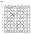
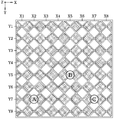
- FIG. 1 illustrates a touch input sensing device in accordance with an embodiment of the present invention.
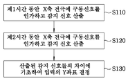
- FIG. 2 is a flowchart for explaining a touch input sensing method according to an embodiment of the present invention.
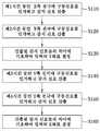
- FIG. 3 is a flowchart for explaining a touch input sensing method according to another embodiment of the present invention.
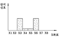
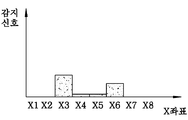
- 4A and 4B show sensing signals measured for an X-axis electrode, respectively, in accordance with one embodiment of the present invention.
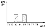
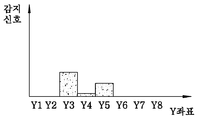
- 5A and 5B show sense signals measured for a Y-axis electrode, respectively, in accordance with one embodiment of the present invention.
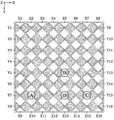
- FIG. 6 illustrates a touch input sensing device according to another embodiment of the present invention.
- FIG. 7 is a flowchart for explaining a touch input sensing method according to another embodiment of the present invention.
- 8A-8C illustrate sensing signals measured for an X-axis electrode in accordance with one embodiment of the present invention.
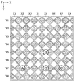
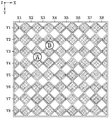
- 9A to 9C are views showing a state of a touch sensing device to which three or more inputs are applied.
- FIG. 10 is a view of a touch input sensing device for explaining a touch input sensing method according to another embodiment of the present invention.
- FIG. 11 is a flowchart for explaining a touch input sensing method according to another embodiment of the present invention.
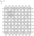
- FIG. 12 is a diagram illustrating a configuration of a touch sensing apparatus according to an embodiment of the present invention.
- the touch sensing apparatus of the present embodiment includes a plurality of, for example, eight X-axis sensing electrodes X1 to X8 and a plurality of, for example, eight Y-axis sensing electrodes Y1 to Y8.
- the axis sensing electrodes X1-X8 extend in the Y axis
- the Y axis sensing electrodes Y1-Y8 extend in the X axis.
- each of the sensing electrodes has a shape in which a plurality of rhombic electrodes are connected to each other so as to cover the entire area of the touch sensing device while minimizing the overlapping area.
- the shape of the sensing electrodes is not limited thereto.
- the X-axis sensing electrodes X1-X8 and the Y-axis sensing electrodes Y1-Y8 may be respectively connected to the driving circuit 10 and the sensing circuit 12 of FIG. 12, for example.
- the driving circuit and the sensing circuit may be implemented in one circuit.
- a capacitive touch sensing device when a touch input is applied to a capacitor formed by an electrode, a change in capacitance occurs by contact, and the presence of the touch input on the touch screen is measured by measuring the change. Will be detected.
- the methods for sensing the change in capacitance there is a method of measuring the voltage value of the electrode while continuously supplying a driving signal, for example, a charge to the electrode.
- a driving signal for example, a charge to the electrode.
- the driving circuit applies electric charge as a driving signal to each of the electrodes X1-X8 and Y1-Y8, and the sensing circuit measures the voltage generated at each electrode according to the application of the electric charge.
- the capacitance at the electrode can be determined, and a signal representing the measured capacitance can be used as a detection signal representing the application of the contact input.
- a capacitive touch sensing device is described, but the present invention is not limited to the capacitive touch sensor, and the present invention can be applied to a touch sensing device using various parameters such as pressure, temperature, resistance, and optical characteristics. .
- a signal representing the value of each parameter can be used as the detection signal.
- the term "sense signal” refers to a signal used to indicate the strength of a touch input, and is described as the intensity of the sense signal is proportional to the touch input.
- the contact input generates a contact region between the sensing electrode and the contact object, and a capacitance change occurs in the sensing electrode according to the size of the contact region.
- the intensity of the sense signal can be used to calculate how wide a contact area the contact input forms with a particular sense electrode.
- the actual implementation may use a sense signal that is inversely proportional to the strength of the touch input, and any signal that directly or indirectly represents the strength of the touch input is included in the sense signal.
- FIG. 2 illustrating a touch input sensing method according to an embodiment of the present invention
- a method of detecting contact input when A and B are generated will be described.
- step S110 a charge is supplied to each of the X-axis sensing electrodes X1-X8 for a predetermined first time, and the strength of the sensing signal that senses a touch input is calculated.
- the sense signal can be calculated by measuring the capacitance at each electrode.
- step S120 charges are supplied to each of the X-axis sensing electrodes X1-X8 for a predetermined second time, and the strength of the sensing signal sensing the touch input is calculated.
- step S130 a sensing electrode having a touch input among Y electrodes is determined based on a difference between the strength of the sensing signal calculated in step S110 and the strength of the sensing signal calculated in step S120.
- the first time and the second time may be determined differently.
- the first time may be sufficient time for the capacitor formed in the sensing electrode to be fully charged, while the second time may be shorter than the first time.
- the second time is a time for partially charging the capacitance formed in the sensing electrode, and the first time may be a time longer than the second time. In another embodiment, the first time may be shorter than the second time.
- the X-axis sensing electrodes X1-X8 are connected to the driving circuit (for example, the driving circuit 10 of FIG. 12) at the upper end thereof in the embodiment of FIG. 1.
- the electric charge applied from the driving circuit is transferred from the upper end (ie, the end connected to the driving circuit) to the lower end (ie, the opposite end of the end connected to the driving circuit) through the electrodes X1-X8, and in the process Pass the resistance by (X1-X8).
- the charging time of the capacitor formed close to the driving circuit i.e., the capacitor with which the relatively small resistance is connected
- the charging time of the capacitor formed ie., the capacitor with the relatively large resistance
- the sensing electrode farther from the driving circuit shows a lower voltage, and accordingly, it is determined that the sensing electrode exhibits a low capacitance, that is, a weak sensing signal. .
- the charge is supplied for a sufficient time, all the capacitors can be fully charged, so the difference in the sense signal is not large.
- the sense signal measured at the X-axis electrodes indicates the position of the electrode where the contact input is present (ie, as shown in FIG. 4A). Coordinates), X3 and X6 are not significantly different.
- a large contact input is detected at X3 where the contact input A, which is a contact input close to the upper end to which the driving circuit is connected, is located.
- relatively small contact inputs are detected at X6.
- step S130 on the basis of the difference in the degree of contact input calculated in steps S110 and S120, the contact input B at the electrode having the large difference (i.e., X6) is far from the driving circuit, i.e., Y It can be determined that the coordinates are large. Therefore, even if two X coordinates X3 and X6 and two Y coordinates Y3 and Y5 are given, it can be determined that the Y coordinate of the contact input at X6 is larger.
- step S130 for the sensing electrode having a larger difference between the sensing signals calculated in steps S110 and S120, the Y direction position or coordinate of the contact input may be determined farther from the charge input terminal of the X-axis electrode. .
- step S110 it is determined whether there are two or more touch inputs from the calculated sense signal, and step S120 may be performed when it is determined in step S110 that there are two or more touch sense electrodes.
- step S110 a charge is supplied to each of the X-axis electrodes X1-X8 and a sensing signal is calculated, and it is determined therefrom that the position where there is a contact input is two or more. In one embodiment, it may be determined that there is a contact input at that location when the sense signal exceeds a predetermined threshold.
- the coordinates of the contact input cannot be determined uniquely, it is limited to the case where both the X coordinate and the Y coordinate of the determined contact input are two or more, and if only one is one, the coordinates of the contact input can be determined.
- the calculation amount and the operation time can be reduced by performing step S120 only when the contact input is determined to be 2 or more in S110.
- steps S110 to S130 may be additionally performed on the Y-axis sensing electrodes Y1-Y8, and are not performed on the X-axis sensing electrodes X1-X8, but not on the Y-axis sensing electrodes Y1-Y8. It may also be performed for.
- steps S140 charges are supplied to each of the Y-axis sensing electrodes Y1-Y8 for a third time, and the sensing signal is detected.
- the third time and the fourth time may be determined differently.
- the third time may be sufficient time for the capacitor formed in the sensing electrode to be fully charged, while the fourth time may be shorter than the third time.
- the fourth time may be a time for partially charging the capacitance formed in the sensing electrode, and the third time may be longer than the fourth time.
- the third time may be shorter than the fourth time.
- the coordinates of the contact input can be determined uniquely.
- the sensing signal measured at the Y-axis electrodes is shown in FIG.
- Y3 and Y5 there is no significant difference in Y3 and Y5
- a large contact input is detected at Y3 where the contact input A, which is a close contact input from the left side to which the driving circuit is connected, is located.
- FIG. 3 another embodiment in which the sensing signal is calculated twice for both the X-axis and Y-axis sensing electrodes has been described.
- the coordinates of the contact inputs can be determined even if two sensing signals are calculated for only one of the X-axis sensing electrode and the Y-axis sensing electrode.
- one detection signal is calculated for the Y-axis electrode to obtain two Y-axis coordinates
- two detection signals are obtained for the X-axis electrode to obtain two X-axis coordinates.
- FIG. 6 is a diagram illustrating a touch input sensing device according to another embodiment of the present invention.
- the touch sensing device of the present embodiment is substantially the same as the apparatus of FIG. 1 except that each sensing electrode is connected to the driving circuit at both ends, for example, at its upper and lower ends in FIG. 6.
- each connection point is provided to each connection point at both ends.
- the upper connection point is given the coordinates of X1 to X8 for the X-axis sensing electrode
- the lower connection point is given the coordinates of X9 to X16.
- the coordinates of Y1 to Y8 are given to the connection point on the left side to the Y-axis sensing electrode, while the coordinates of Y9 to Y16 are given to the connection point on the right side.
- the method of assigning the coordinates is not limited to the illustrated ones, and if a separate monitoring signal can be obtained at both ends of each sensing electrode and can be distinguished from them, the coordinates may be provided in any manner. It is also possible to distinguish the sensing electrodes in other ways.
- each sensing electrode is identified by the coordinates of X1-X8, and when driving at the lower end, it is identified by the coordinates of X9-X16.
- each sensing electrode is identified by the coordinates of Y1-Y8, and when driving on the right side, it is identified by the coordinates of Y9-Y16.
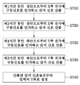
- step S720 charges are supplied to each of the X-axis sensing electrodes X1 to X8 for a second predetermined time on the same side as S710, and the strength of the sensing signal is calculated.
- the first time and the second time may be different from each other as in the previous embodiment.
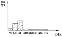
- step S730 a charge is supplied to each of the X-axis sensing electrodes X9-X16 for a predetermined third time at the side different from step S710 to calculate the intensity of the sensing signal.
- Y is based on the difference between the strength of the sensing signal calculated in step S710 and the strength of the sensing signal calculated in step S720 and the difference between the strength of the sensing signal calculated in step S710 and the strength of the sensing signal calculated in step S730.
- the sensing electrode in which the touch input exists among the electrodes is determined (step S740). As described above, in the embodiment of FIG. 7, the detection signal is repeatedly calculated with different driving directions for the same electrode. Therefore, unlike the embodiment of Fig. 2, two pairs of data for determining the position of the contact input can be obtained, and the accuracy of the contact input position calculation can be improved.
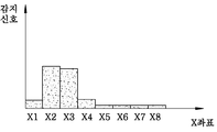
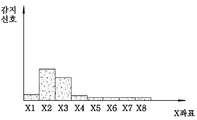
- the sensing signals calculated in steps S710 and S720 are as shown in FIGS. 8A and 8B, respectively.
- 8A and 8B illustrate the case where the first time is sufficient time to fully charge the capacitor of the sensing electrode, and the second time is shorter than the first time.
- the sensing inputs are arranged adjacent to each other, the difference in the intensity of the sensing signal at the coordinates X2 and X3 is not large.
- a signal comparable with the sensing signal obtained in step S730 may be obtained, including step S725 of driving the sensing electrode in the same direction as step S730 before step S730. That is, it is also possible to drive the sensing electrodes twice in different directions for different times. However, if the sensing electrode is driven for a time sufficient to charge the capacitor of the sensing electrode in step S725, substantially the same sensing signal as in step S710 will be obtained, so in steps S725 and S725, the capacitors of the sensing electrode are completely removed. It would be desirable if it was driven for a period of time that could not be charged.
- step S710 it is determined whether there are two or more touch inputs from the calculated sensing signal, and steps S720 and S730 can be performed only when it is determined in step S710 that there are two or more touch sensing electrodes.
- step S710 electric charges are supplied to each of the X-axis electrodes X1-X8, and a sensing signal is calculated, from which it is determined whether the position at which there is a contact input is two or more. In one embodiment, it may be determined that there is a contact input at that location when the sense signal exceeds a predetermined threshold. Performing steps S720 and S730 only when the contact input is determined to be 2 or more in step S710 can reduce the amount of calculation and the operation time.
- steps S710 to S740 may be additionally performed for the Y-axis sensing electrode, or may be performed only for the Y-axis sensing electrode and not for the X-axis sensing electrode. That is, first, the driving is performed for the sensing electrodes Y1-Y8 for a first time, and the driving for the sensing electrodes Y1-Y8 is performed for a second time different from the first time. Further, after the driving is performed for the sensing electrodes Y9-Y16 for a third time different from the first time, the X coordinate of the contact input is determined using the sensing signal obtained by three drivings. For example, in the example of FIG. 3, it is possible to determine that the contact input of A and B, rather than C and D, is applied by grasping that the sensing input is applied near the left side in Y2.
- the method of the present invention can be used to determine the exact position of the contact input even when there are three or more contact inputs. That is, three coordinate pairs can be determined by obtaining three coordinates for each of the X-axis and the Y-axis, and also grasping the relative position of the sensing input at each coordinate based on the difference of the sensed signals calculated twice.
- additional processing may be required, which will be described with reference to FIGS. 9A to 9C.
- 9A shows a touch input sensing device to which three touch inputs are applied
- 9b and 9c show a touch input sensing device to which four touch inputs are applied.
- the number of contact inputs can be determined based on the strength of the sense signal at each sense electrode. For example, in order to grasp the characteristics of the contact input of FIG. 9B, the intensity of the detection signal measured at the Y7 position is stronger than that of the contact input shown in FIG. 9A through the second driving on the Y axis. Figure out. This makes it possible to grasp that the Y7 electrode has three contact inputs, and determine the coordinates of the four contact inputs based on the information.
- four contact inputs A, B, C, and D may be recognized using sense electrodes connected at both ends to the drive circuit as shown in FIG. 9C.
- three X coordinates (X2, X5, X7) are obtained through one drive on the X-axis sensing electrode, and two Y coordinates (Y5, Y7) through one drive on the Y-axis sensing electrode.
- the second drive from the upper end with respect to the X-axis sensing electrode can be seen that the contact input at X5 is relatively close from the upper end.
- the third drive from the bottom to the X-axis sensing electrode it can be seen that the contact input at X13 is relatively close to the bottom.
- two contact inputs A and B are applied to one sensing electrode X3. Since these contact inputs are only partially applied to the sensing electrode X3, the position of the contact input (i.e., the position of the center of the touch input) should be determined as the position between X3 and the adjacent sensing electrode, not the sensing electrode X3. Specifically, since contact input A is applied to both sensing electrodes X2 and X3 and contact input B is applied to both sensing electrodes X3 and X4, the position of contact input A is between sensing electrodes X2 and X3 and the position of contact input B. Is between the sensing electrodes X3 and X4.
- the present embodiment calculates the intensity of the sense signal by each contact input by driving the sense electrode twice for different time to calculate the sense signal.
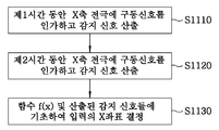
- the method of the present embodiment applies a driving signal to the sensing electrode X3 for the first time and calculates the sensing signal (step S1110).
- a driving signal is applied to the sensing electrode X3 for the second time and the sensing signal is calculated (step S1120).
- the sensing signal at the distance x from the charge input terminal when the driving signal is applied to the sensing electrode X3 for the first time is f 1 (x)
- the charge when the driving signal is applied to the sensing electrode for the second time is given by f 2 (x).
- This function f (x) is, as described above, due to the difference in the magnitude of the resistance passing as the driving signal is transmitted on the sensing electrode, the time constant changes according to the position on the electrode, and the magnitude of the sensing signal measured accordingly. Is a function representing the relation to be changed and may be calculated mathematically or determined through experiments.
- the function f (x) may be stored in advance in, for example, an internal memory of the touch sensor chip, and used to calculate the contact position.
- step S1130 it is possible to determine the strength of the detection signal generated by each contact input based on the known function f (x) and the detection signals measured in the first and second steps. Specifically, since the sensing signal I 1 calculated in the first step is the sum of the sensing signal by the touch input A and the sensing signal for the touch input B, it may be given by Equation 2 below.
- S a and S b represent the sensitivity of the detection signal by the contact inputs A and B, respectively, and are values proportional to the contact area.
- a and b are values representing distances or Y coordinates from the charge input terminals of the contact inputs A and B, respectively, and may be determined in various ways. For example, a and b may be determined by detecting a sensing signal at the Y-axis sensing electrode.
- the sensing signal I 2 calculated in the second step may be given by the following equation (3).
- the sensitivity S a and S b by the respective contact inputs can be obtained, and accordingly, it can be seen how much sensed signal each contact input generated.
- the position determined here is a position in a direction intersecting with the extending direction of the sensing electrode (that is, the Y axis direction), for example, the X coordinate of the contact input.
- the methods described above may be performed by a driving circuit and / or a sensing circuit.
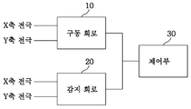
- An example of the configuration of the touch input sensing device is shown in FIG. 12.
- the driving circuit 10 is connected to the X-axis sensing electrode and / or Y-axis sensing electrode, and applies a driving signal to the electrode for a predetermined time as needed.
- the driving circuit 10 may include two driving circuits respectively connected to both ends of the electrode.
- one driving circuit may be connected to both ends of the electrode to perform separate driving from both ends of the electrode.
- the sensing circuit 20 is connected to the X-axis sensing electrode and the Y-axis sensing electrode, and calculates a sensing signal for each electrode in response to the driving signal applied from the driving circuit 10.
- the driving circuit 10 and the sensing circuit 20 are controlled by the controller 30 so that the application of the driving signal and the calculation of the sensing signal can be synchronized.
- These driving circuits and sensing circuits may be separate circuits or may be integrated circuits.
- Each drive circuit and sense circuit may include one or more modules for performing the above methods, which may be implemented as software modules, hardware modules, or a combination thereof. Such drive and sense circuits may be operable to perform the method under the control of a controller.
- one or both of the above-described driving circuit and sensing circuit may be included in the controller. In this case, it is also possible for the controller to be configured in the form of an integrated circuit.
- the methods may be implemented in the form of a program, and may be performed by a computer.
Landscapes
- Engineering & Computer Science (AREA)
- General Engineering & Computer Science (AREA)
- Theoretical Computer Science (AREA)
- Human Computer Interaction (AREA)
- Physics & Mathematics (AREA)
- General Physics & Mathematics (AREA)
- Position Input By Displaying (AREA)
Abstract
L'invention concerne une méthode de détection d'entrées par contact dans un appareil de détection d'entrée par contact comprenant une électrode de détection. La méthode de détection d'entrées par contact comprend : une première étape d'activation d'une borne d'entrée de l'électrode de détection afin qu'un signal d'excitation soit fourni pendant une première période, de manière qu'un signal détecté soit obtenu; une deuxième étape d'activation de la borne d'entrée de l'électrode de détection afin qu'un signal d'excitation soit fourni pendant une deuxième période, de manière qu'un signal détecté soit obtenu; et une troisième étape de détermination de l'emplacement de l'entrée par contact en fonction de la différence entre le signal détecté obtenu dans la première étape et le signal détecté obtenu dans la deuxième étape, la première et la deuxième période étant différentes. Les coordonnées des entrées par contact peuvent ainsi être déterminées avec précision même lorsque deux entrées par contact ou plus sont appliquées.
Applications Claiming Priority (2)
| Application Number | Priority Date | Filing Date | Title |
|---|---|---|---|
| KR1020100069075A KR101696386B1 (ko) | 2009-12-11 | 2010-07-16 | 복수의 접촉 입력을 감지하는 방법 및 장치 |
| KR10-2010-0069075 | 2010-07-16 |
Publications (2)
| Publication Number | Publication Date |
|---|---|
| WO2012008751A2 true WO2012008751A2 (fr) | 2012-01-19 |
| WO2012008751A3 WO2012008751A3 (fr) | 2012-05-31 |
Family
ID=45470131
Family Applications (1)
| Application Number | Title | Priority Date | Filing Date |
|---|---|---|---|
| PCT/KR2011/005153 Ceased WO2012008751A2 (fr) | 2010-07-16 | 2011-07-13 | Méthode et appareil de détection d'une pluralité d'entrées par contact |
Country Status (1)
| Country | Link |
|---|---|
| WO (1) | WO2012008751A2 (fr) |
Family Cites Families (4)
| Publication number | Priority date | Publication date | Assignee | Title |
|---|---|---|---|---|
| US8279180B2 (en) * | 2006-05-02 | 2012-10-02 | Apple Inc. | Multipoint touch surface controller |
| WO2007146783A2 (fr) * | 2006-06-09 | 2007-12-21 | Apple Inc. | Dispositifs d'affichage à cristaux liquides équipé d'un écran tactile |
| KR100913741B1 (ko) * | 2007-08-07 | 2009-08-24 | 에이디반도체(주) | 다축 터치감지전극라인을 가지는 정전용량센서터치감지전극판, 이를 이용하는 터치스크린 및 터치 패드 |
| KR100978461B1 (ko) * | 2008-07-04 | 2010-08-26 | 안영수 | 고감도 디지탈방식의 정전용량터치패널장치 |
-
2011
- 2011-07-13 WO PCT/KR2011/005153 patent/WO2012008751A2/fr not_active Ceased
Also Published As
| Publication number | Publication date |
|---|---|
| WO2012008751A3 (fr) | 2012-05-31 |
Similar Documents
| Publication | Publication Date | Title |
|---|---|---|
| CN104679358B (zh) | 一种终端 | |
| CN105531655B (zh) | 翻转的单元传感器图案 | |
| WO2009142453A2 (fr) | Procédé et appareil pour détecter des entrées à effleurements multiples | |
| WO2011025170A2 (fr) | Appareil d'entrée et procédé permettant de détecter la position de contact d'un appareil d'entrée | |
| WO2014030804A1 (fr) | Dispositif d'affichage, et procédé de commande d'un dispositif d'affichage | |
| US20110234523A1 (en) | Touch sensing system, electronic touch apparatus, and touch sensing method | |
| WO2014018732A2 (fr) | Détection d'entrée gestuelle et tactile par détection de force | |
| WO2015088263A1 (fr) | Appareil électronique fonctionnant conformément à l'état de pression d'une entrée tactile, et procédé associé | |
| US20130027344A1 (en) | Apparatus Including a Touch-Sensitive Interface Including a Serpentine Electrode Pattern | |
| JP2015049895A (ja) | タッチパネルの入力信号識別方法 | |
| KR102569170B1 (ko) | 사용자 입력이 유지되는 시간에 기반하여 사용자 입력을 처리하는 방법 및 장치 | |
| WO2014104642A1 (fr) | Appareil et procédé de détection de toucher | |
| WO2019182414A1 (fr) | Dispositif électronique et procédé de modification d'une condition pour déterminer une entrée tactile comme étant une entrée de pression | |
| US20150378496A1 (en) | Capacitive input sensing in the presence of a uniform conductor | |
| WO2014014316A1 (fr) | Procédé et dispositif de détection de toucher | |
| WO2014014240A1 (fr) | Souris de doigt de type à contact et son procédé de fonctionnement | |
| CN107145232A (zh) | 一种利用电容检测识别用户手部行为的方法和装置 | |
| CN102231091B (zh) | 一种用于基于单点触摸屏实现多点识别的方法及设备 | |
| WO2018169209A1 (fr) | Dispositif d'entrée, système électronique et procédé de commande associé | |
| WO2012093873A2 (fr) | Procédé permettant de détecter la position de contact d'un écran tactile et écran tactile utilisant celui-ci | |
| WO2014054878A2 (fr) | Panneau tactile doté d'une seule structure stratifiée permettant d'accroître la sensibilité sans provoquer d'interférence | |
| TWI628417B (zh) | 偵測若干物體的感測器裝置及方法以及具有感測器裝置之電手持裝置 | |
| WO2010008148A2 (fr) | Dispositif et procédé de reconnaissance de mouvement | |
| WO2010110532A2 (fr) | Dispositif d'entrée complexe à fonction de clavier tactile | |
| KR101696386B1 (ko) | 복수의 접촉 입력을 감지하는 방법 및 장치 |
Legal Events
| Date | Code | Title | Description |
|---|---|---|---|
| 121 | Ep: the epo has been informed by wipo that ep was designated in this application |
Ref document number: 11807036 Country of ref document: EP Kind code of ref document: A2 |
|
| NENP | Non-entry into the national phase |
Ref country code: DE |
|
| 122 | Ep: pct application non-entry in european phase |
Ref document number: 11807036 Country of ref document: EP Kind code of ref document: A2 |