WO2012008855A1 - Method and system for deterring animals - Google Patents
Method and system for deterring animals Download PDFInfo
- Publication number
- WO2012008855A1 WO2012008855A1 PCT/NZ2011/000130 NZ2011000130W WO2012008855A1 WO 2012008855 A1 WO2012008855 A1 WO 2012008855A1 NZ 2011000130 W NZ2011000130 W NZ 2011000130W WO 2012008855 A1 WO2012008855 A1 WO 2012008855A1
- Authority
- WO
- WIPO (PCT)
- Prior art keywords
- filter
- rate
- light
- polarisation
- polarising
- Prior art date
- Legal status (The legal status is an assumption and is not a legal conclusion. Google has not performed a legal analysis and makes no representation as to the accuracy of the status listed.)
- Ceased
Links
Classifications
-
- A—HUMAN NECESSITIES
- A01—AGRICULTURE; FORESTRY; ANIMAL HUSBANDRY; HUNTING; TRAPPING; FISHING
- A01M—CATCHING, TRAPPING OR SCARING OF ANIMALS; APPARATUS FOR THE DESTRUCTION OF NOXIOUS ANIMALS OR NOXIOUS PLANTS
- A01M29/00—Scaring or repelling devices, e.g. bird-scaring apparatus
- A01M29/06—Scaring or repelling devices, e.g. bird-scaring apparatus using visual means, e.g. scarecrows, moving elements, specific shapes, patterns or the like
- A01M29/10—Scaring or repelling devices, e.g. bird-scaring apparatus using visual means, e.g. scarecrows, moving elements, specific shapes, patterns or the like using light sources, e.g. lasers or flashing lights
-
- A—HUMAN NECESSITIES
- A01—AGRICULTURE; FORESTRY; ANIMAL HUSBANDRY; HUNTING; TRAPPING; FISHING
- A01M—CATCHING, TRAPPING OR SCARING OF ANIMALS; APPARATUS FOR THE DESTRUCTION OF NOXIOUS ANIMALS OR NOXIOUS PLANTS
- A01M29/00—Scaring or repelling devices, e.g. bird-scaring apparatus
-
- F—MECHANICAL ENGINEERING; LIGHTING; HEATING; WEAPONS; BLASTING
- F21—LIGHTING
- F21V—FUNCTIONAL FEATURES OR DETAILS OF LIGHTING DEVICES OR SYSTEMS THEREOF; STRUCTURAL COMBINATIONS OF LIGHTING DEVICES WITH OTHER ARTICLES, NOT OTHERWISE PROVIDED FOR
- F21V9/00—Elements for modifying spectral properties, polarisation or intensity of the light emitted, e.g. filters
- F21V9/14—Elements for modifying spectral properties, polarisation or intensity of the light emitted, e.g. filters for producing polarised light
Definitions
- the invention relates to systems and methods for deterring animals, in particular but not exclusively, to systems and methods for deterring birds.
- the invention provides an animal deterrence apparatus including a light source providing light in a wavelength range detectable by a target animal and a polariser, the system configured to project polarised light over an area in which animals are to be deterred.
- the polariser is a variable element configured to vary the polarisation of the projected light over time.
- the variable element is a rotating polarising filter.
- the filter is a plane polarising filter.
- the filter rotates at a rate in the range 1 to 500 cycles per minute.
- the filter rotates at a rate in the range 1 to 75 cycles per minute.
- the rate of rotation of the filter varies with time.
- the rate of rotation varies in a random manner.
- the target animal is a bird.
- This first aspect also encompasses an animal deterrence system including two or more such apparatuses.
- the invention provides a method for deterring animals, including: projecting polarised light in a wavelength range detectable by a target animal.
- the polarisation of the projected light is varied over time.
- the polarisation is varied using a rotating polarising filter.
- the filter is a plane polarising filter.
- the filter is rotated at a rate in the range 1 to 500 cycles per minute.
- the filter is rotated at a rate in the range 1 to 75 cycles per minute.
- the method includes varying the rate of rotation of the filter with time.
- the rate of rotation is varied in a random manner.
- the target animal is a bird.
- Figure 1 is a schematic view of an animal deterring system according to one embodiment
- Figure 2 shows a system according to a further embodiment
- Figure 3 shows a variable polariser arrangement from the system of Figure 2;
- Figure 4 shows a roller from the arrangement of Figure 3;
- Figure 5 shows a system according to a further embodiment
- Figure 6 is a graph of testing results of the Applicant's system.
- sugars can have an effect on the polarisation of light.
- different sugars are dextrorotary (e.g. glucose, sucrose, fructose, maltose) and others are levorotary (e.g. lactose). These sugars rotate light to the right (for dextrorotary sugars) or the left (for levorotary sugars).
- dextrorotary e.g. glucose, sucrose, fructose, maltose
- levorotary e.g. lactose
- These sugars rotate light to the right (for dextrorotary sugars) or the left (for levorotary sugars).
- the Applicant believes that birds may be attracted to ripe fruit by the effect that sugars within the fruit have on the polarisation of light. It is possible, for example, that birds may see a halo, spike or other visual effect around a ripe berry.
- the Applicant has invented a method and system for deterring birds and/or other animals based on their sensitivity to polarised light.
- the Applicant's invention relies on projecting polarise light over an area in which animals are to be deterred, in order to confuse the birds and/or other animals, disturb them, make them uncomfortable or otherwise deter them.
- the invention also involves varying the polarisation of light in order to confuse the birds and/or other animals, disturb them, make them uncomfortable or otherwise deter them.
- FIG. 1 illustrates a deterrent system according to one embodiment.
- the system 1 includes a power source 2 which powers a light source 3.
- the power source 2 may be any suitable source, include a mains power connection, battery, photovoltaic system etc.
- a light sensor switch may be incorporated to turn the system "off during hours of darkness.
- the light source 3 may also be any suitable conventional source, including a floodlight, for example.
- a floodlight for example.
- when the weather is suitable it may be possible to use sunlight with a reflector.
- the light source should be such that the wavelength of light can be detected by the animal to be deterred.
- a broad wavelength range may be used.
- the Applicant believes that birds are sensitive to what humans call the visible spectrum.
- the Applicant understands that there are differences in sensitivity, particularly at the infrared and ultraviolet ends of the spectrum.
- a source providing a broad wavelength range in the visible spectral region will generally be suitable.
- the system 1 also includes a variable optical element 4, which in one embodiment is a plane polarising filter arranged to rotate.
- the light source produces a beam of light indicated by the dashed lines 6.
- This beam of light passes through the rotating plane polariser 4 and is projected over an area in which birds are to be deterred.
- the beam is projected over a vineyard 8 including rows of grapes 9.
- the beam of light projected over the vineyard therefore is plane polarised, with a rotating plane of polarisation.
- the rotating filter may rotate at a rate in the range 1 to 500 cycles per minute, preferably 1 to 75 cycles per minute. Suitable rates may be different for different target animals. In addition, in order to reduce the risk of animals becoming accustomed to the varying polarisation, the rate of rotation may be varied, possibly in a random manner.
- the rotating filter may be driven by means of a belt drive, or similar, connected to a variable speed motor. Alternatively a motorised drive with a variable gearing could be used. A brushless DC 12V or 24V motor may be suitable in some applications.
- the filter may be mounted in a frame with four rollers, one of which is driven by a friction drive roller of suitable diameter. Alternatively the rotating filter may be rotatably mounted on an axle. In some applications one or more vanes may be provided on the rotating filter such that rotation is driven by the wind.
- Figures 2 to 4 show a further embodiment.
- the apparatus may include a support 10 suitable for the desired application.
- the support 10 may be a permanently fixed post or a metal tubular post fixed at its lower end to a moveable base (not shown). Alternatively, the apparatus may be fixed to the side of a building or other structure.
- a power source 2 which may any of the sources discussed above, supplies power over connection 12 to a power and control unit 13.
- the supplied power is preferably mains power (230V AC at 50Hz in New Zealand, but other voltages and frequencies in other countries).
- the power and control unit 13 supplies power over connection 14, preferably at the mains voltage, to a ballast 15.
- the ballast 15 is connected to a light source 3 over connection 16.
- the light source 3 may be supported on a light source support 17 mounted to a platform 18 on the support 10. Any suitable arrangement for supporting the light source 3 on the support 10 may be used.
- a ballast 14 is supported on the light source support 15, but again any suitable support arrangement may be used where a ballast is required.
- the light source 3 may be a compact fluorescent bulb of a suitable power rating, e.g. 120 Watts, emitting generally white light.
- a suitable power rating e.g. 120 Watts
- the Applicant believes such a light source to be effective over a range of more than 100 metres.
- Other power ratings may be suited to other applications.
- small domestic units could be made incorporating a low power light source (such as an LED source) with a small rotating polariser.
- a small scale device could be used to protect a small strawberry patch or fruit tree or the like.
- the light source may be mounted in a floodlight housing or similar to project light forwards.
- the power and control unit may also provide power to a drive arrangement 20 over connection 21.
- the power is supplied at a suitable voltage for the drive motor.
- the drive arrangement preferably includes a 24DC motor, with the power and control unit including suitable circuitry to convert mains power to 24 V DC. Such circuitry is well understood by the skilled reader and need not be discussed further.
- variable polarising element 4 driven by the drive arrangement 20.
- the variable polarising element 4 is shown in more detail in the front view of Figure 3.
- a framework 30 may be mounted to the platform 18 and may include four side members 31 arranged to form a square or diamond.
- a roller 33, 34 is mounted using front and back corner plates 35, of which only the front corner plates can be seen in Figure 3.
- Each roller 33, 34 is mounted on a bolt 36 or other component providing an axle.
- These rollers 33, 34 support a polarising filter 38 which is generally formed as a disc.
- the rollers may be formed in three sections to provide a recessed central region 39 between two larger diameter outer regions 40.
- the edge of the polarising filter 38 will ride securely in these central recesses, keeping the filter 38 properly aligned within the framework 30.
- Three of the corners have corner plates 35 formed with slots 42, which allow the position of the bolts 36 to be adjusted for insertion, removal or adjustment of the polarising filter 38.
- rollers may be driven for rotation of the polarising filter 38.
- roller 33 is driven.
- This roller is mounted to a shaft of the motor 20. Driven rotation of this roller causes rotation of the polarising filter 38, which rides freely over the other rollers 34.
- the rollers 33, 34 may be mounted in any suitable manner using bearings, spacers etc to mount the rollers and to reduce friction.
- the rollers may be made from any suitable material, including plastics materials. Nylon may be suitable for some applications.
- the control and power unit 13 may control the supply of power to the system and the rotation of the polarising filter 38 in any desired manner for the particular application.
- the rotation of the polarising filter 38 may simply be driven at constant speed, or in an irregular or random manner.
- the control and power unit may receive input from users and from sensors. Thus users may interact with user input devices 48 to turn the system on and off, or to provide a schedule for operation of the system.
- Sensors 49 may include light sensors, for turning the unit off after dark and on at dawn.
- Sensors 49 may also include, for example, temperature sensors such that the system can be shut down in freezing conditions to prevent damage to the moving parts.
- temperature sensors such that the system can be shut down in freezing conditions to prevent damage to the moving parts.
- any sensors suitable for the application may be used.
- the control function may be separated from the power supply to create a separate control unit.
- Figure 5 shows a wider area embodiment in which a number of lighting units 50 are powered and controlled.
- a system may be employed in a large scale vineyard or orchard, or at an airport, for example.
- Each lighting unit includes a light source and variable polarising element, and these may be arranged substantially as described above with reference to Figures 2 to 4.
- a power switching unit 51 receives power from power source 2 (preferably a mains source) and distributes power to the lighting units 50 over a network of power lines 52.
- power source 2 preferably a mains source
- a control unit 54 is connected to each light source via control lines 55. Any suitable network of control lines may be used.
- the control unit controls parameters of the polarisation variation, such as rate of variation (e.g. rate of rotation).
- the control unit may be connected to the power switching unit 51 by control line 57.
- the control unit controls the switching unit to turn the power supply to the system on or off.
- the control unit has its own connection 58 to power supply 2, independent of the switching unit 51.
- the control unit may receive input from a number of sources.
- a user may input control parameters at user input device 60.
- the control unit may receive sensor data from sensors 61 , 62.
- the embodiment shown has a single switching unit to switch power to the whole system on or off, in some embodiments a more complex system could be employed that is capable of switching each lighting unit on or off, or possibly switching small groups of lighting units on off.
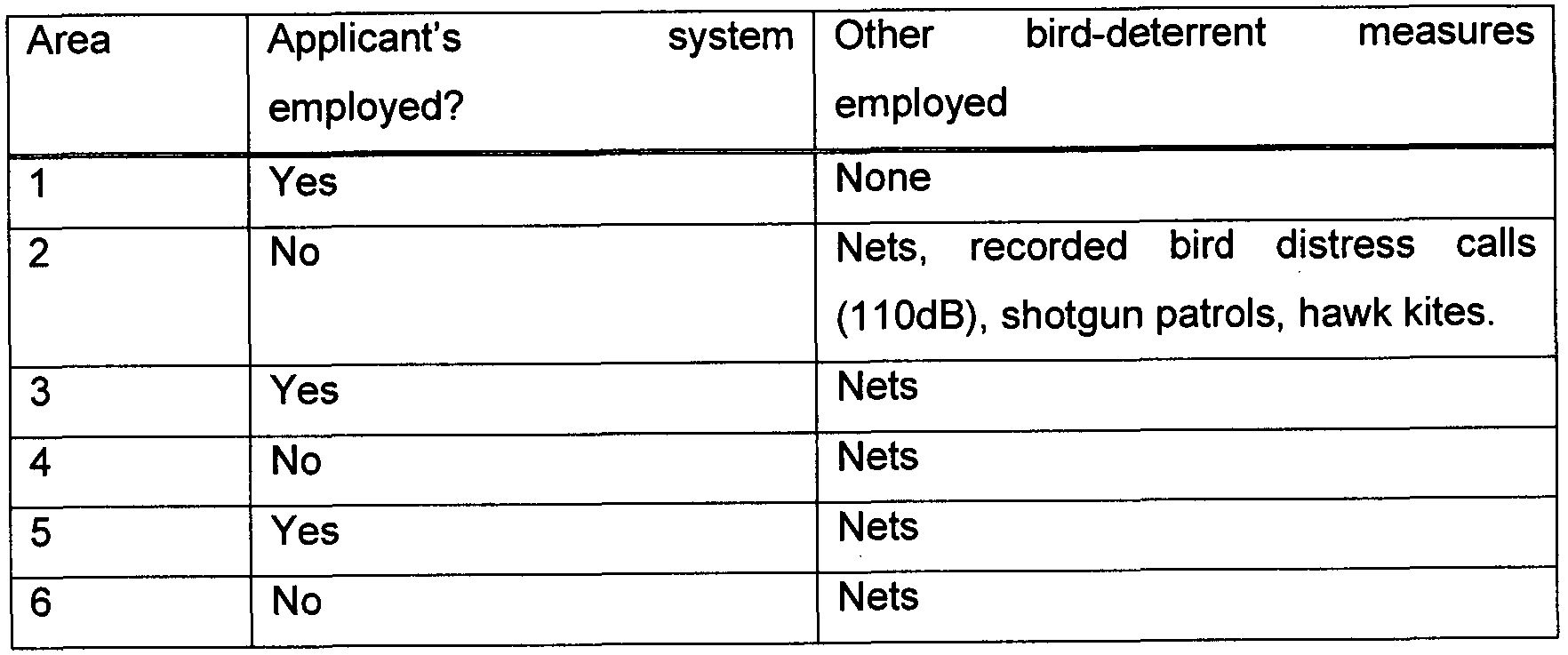
- Figure 6 is a graph showing results of testing on vineyards in the Central Otago region of New Zealand.
- the vertical axis shows a percentage value for the number of grapes damaged in samples taken from each vineyard. Tests were made in six areas (Areas 1 , 2, 3, 4, 5 and 6) as set out in the following table:
- Areas 1 and 2 neighbour each other, as do areas 3 and 4, and areas 5 and 6. Lights were arranged in each area with around 1 light per hectare. The density of lights used will in general depend on the power of the lights, the width of their beams and factors specific to the application such as obstructions, geography etc. The results show a strong reduction in damage at both Areas 3 (compared to 4) and 5 (compared to 6) from the use of the Applicant's system.
- a number of light sources may be used, with each light source having a filter in a different polarisation.
- the light sources can then be switched on and off in sequence to project light of varying polarisation.
- preferred embodiments require the variation of the polarisation, e.g. rotation of the plane of polarisation, in some applications projection of unvarying polarised light may be used or unvarying polarised light may be switched on and off, possibly in an irregular manner.
- the variation of the optical property is preferred as it is less likely that animals will acclimatise, thereby reducing the effectiveness of the deterrence system.
- the Applicant's invention may be useful in deterring birds in order to prevent bird damage.
- the invention may be used to protect vineyards, orchards etc, at airports, cities, on ships or in any other environment where birds cause damage or are otherwise undesirable.
- the Applicant's invention may also find application in deterring other animals which are sensitive to the polarisation of light, particularly damage causing insects such as bees and wasps.
- An account of animal sensitivity to polarised light can be found in "Polarized Light in Animal Vision” by Horvath and Varju, Springer-Verlag 2003, ISBN: 3540404570, the contents of which are incorporated by reference herein.
- the Applicant's invention will provide a significant cost advantage over previous methods, particularly because the large labour costs of installing and removing physical barriers such as nets will be avoided.
- the Applicant's invention has minimal environmental impact and is unobtrusive, in contrast to previous systems, many of which have required sudden explosive reports or ugly physical barriers.
Landscapes
- Life Sciences & Earth Sciences (AREA)
- Engineering & Computer Science (AREA)
- Zoology (AREA)
- Insects & Arthropods (AREA)
- Pest Control & Pesticides (AREA)
- Wood Science & Technology (AREA)
- Birds (AREA)
- Environmental Sciences (AREA)
- Physics & Mathematics (AREA)
- Optics & Photonics (AREA)
- Spectroscopy & Molecular Physics (AREA)
- General Engineering & Computer Science (AREA)
- Catching Or Destruction (AREA)
- Investigating Or Analysing Biological Materials (AREA)
Abstract
Description
Claims
Priority Applications (12)
| Application Number | Priority Date | Filing Date | Title |
|---|---|---|---|
| US13/810,063 US9226492B2 (en) | 2010-07-14 | 2011-07-13 | Method and system for deterring animals |
| AU2011277116A AU2011277116B2 (en) | 2010-07-14 | 2011-07-13 | Method and system for deterring animals |
| CN201180034594.2A CN103108544B (en) | 2010-07-14 | 2011-07-13 | For deterring the method and system of animal |
| EA201390112A EA027338B1 (en) | 2010-07-14 | 2011-07-13 | Method and system for deterring animals |
| EP11807116.6A EP2592926B1 (en) | 2010-07-14 | 2011-07-13 | Method and system for deterring animals |
| BR112013000935-7A BR112013000935B1 (en) | 2010-07-14 | 2011-07-13 | polarized light apparatus, method and system for frightening animals |
| MX2013000418A MX2013000418A (en) | 2010-07-14 | 2011-07-13 | Method and system for deterring animals. |
| JP2013519620A JP2013532983A (en) | 2010-07-14 | 2011-07-13 | Methods and systems for driving away animals |
| CA2803291A CA2803291C (en) | 2010-07-14 | 2011-07-13 | Method and system for deterring animals |
| ES11807116T ES2758874T3 (en) | 2010-07-14 | 2011-07-13 | Systems and methods to discourage animals |
| IL224124A IL224124A (en) | 2010-07-14 | 2013-01-07 | Method and system for deterring animals |
| ZA2013/00574A ZA201300574B (en) | 2010-07-14 | 2013-01-22 | Method and system for deterring animals |
Applications Claiming Priority (2)
| Application Number | Priority Date | Filing Date | Title |
|---|---|---|---|
| NZ58679710 | 2010-07-14 | ||
| NZ586797 | 2010-07-14 |
Publications (2)
| Publication Number | Publication Date |
|---|---|
| WO2012008855A1 true WO2012008855A1 (en) | 2012-01-19 |
| WO2012008855A9 WO2012008855A9 (en) | 2012-03-08 |
Family
ID=45469663
Family Applications (1)
| Application Number | Title | Priority Date | Filing Date |
|---|---|---|---|
| PCT/NZ2011/000130 Ceased WO2012008855A1 (en) | 2010-07-14 | 2011-07-13 | Method and system for deterring animals |
Country Status (14)
| Country | Link |
|---|---|
| US (1) | US9226492B2 (en) |
| EP (1) | EP2592926B1 (en) |
| JP (2) | JP2013532983A (en) |
| CN (1) | CN103108544B (en) |
| AU (1) | AU2011277116B2 (en) |
| BR (1) | BR112013000935B1 (en) |
| CA (1) | CA2803291C (en) |
| CL (1) | CL2013000144A1 (en) |
| EA (1) | EA027338B1 (en) |
| ES (1) | ES2758874T3 (en) |
| IL (1) | IL224124A (en) |
| MX (1) | MX2013000418A (en) |
| WO (1) | WO2012008855A1 (en) |
| ZA (1) | ZA201300574B (en) |
Cited By (1)
| Publication number | Priority date | Publication date | Assignee | Title |
|---|---|---|---|---|
| US11401015B2 (en) | 2019-12-19 | 2022-08-02 | Peter J. Grossman | Portable survival device |
Families Citing this family (11)
| Publication number | Priority date | Publication date | Assignee | Title |
|---|---|---|---|---|
| FR2982736B1 (en) * | 2011-11-18 | 2013-12-13 | Airbus Operations Sas | METHOD AND DEVICE FOR VISIBLE IMPARRINATION OF AVIAN SPECIES, ESPECIALLY FOR AN AIRCRAFT. |
| IL229708B (en) * | 2012-11-28 | 2019-09-26 | Itzhak Shefer | See -through manhole cover |
| NL2010805C2 (en) * | 2013-05-15 | 2014-11-24 | Steinar Holding B V | DEVICE AND METHOD FOR THE BIRD OF BIRDS BY LASER. |
| US10398138B2 (en) * | 2014-04-08 | 2019-09-03 | Lampman Wildlife Management Services Limited | Wildlife exclusion composition and assembly |
| US10220959B2 (en) | 2016-07-01 | 2019-03-05 | Maurice A Khawam | Aircraft lighting system |
| US10351258B1 (en) | 2016-07-18 | 2019-07-16 | Lumen International, Inc. | System for protecting aircraft against bird strikes |
| CN109006698B (en) * | 2018-06-27 | 2020-05-15 | 中国农业科学院蜜蜂研究所 | Device and method for identifying aggressivity of bees |
| BR202018069022Y1 (en) * | 2018-09-19 | 2023-01-17 | Virginia Kieling Steiger | CONSTRUCTIVE ARRANGEMENT OF APPLIANCE TO SCARE BIRDS AND OTHER ANIMALS |
| KR102176480B1 (en) * | 2018-11-30 | 2020-11-09 | 정혁 | Wasp killing device |
| JP6684506B1 (en) * | 2019-08-29 | 2020-04-22 | アイ・エヌ製薬株式会社 | Animal repellent device and animal repellent method |
| CN112129054A (en) * | 2020-09-08 | 2020-12-25 | 韦先忠 | Fishing net airing equipment for fishing aquatic products |
Citations (1)
| Publication number | Priority date | Publication date | Assignee | Title |
|---|---|---|---|---|
| JP2010220542A (en) * | 2009-03-24 | 2010-10-07 | Tokyo Electric Power Co Inc:The | Bird escape device and wind power generator |
Family Cites Families (15)
| Publication number | Priority date | Publication date | Assignee | Title |
|---|---|---|---|---|
| GB919368A (en) | 1960-09-22 | 1963-02-27 | Nat Res Dev | Improvements relating to the measurement of distance |
| DE2450456A1 (en) | 1974-10-24 | 1976-05-06 | Bosch Gmbh Robert | FOG LIGHTS |
| DE2753029B1 (en) * | 1977-11-28 | 1979-03-29 | Swarovski & Co | Wildlife warning reflector |
| US6058661A (en) * | 1986-10-02 | 2000-05-09 | Hand; Herbert H. | Method and apparatus for preventing crawling insects and other crawling pests gaining access to sources of water |
| US6208463B1 (en) | 1998-05-14 | 2001-03-27 | Moxtek | Polarizer apparatus for producing a generally polarized beam of light |
| JP3756320B2 (en) * | 1998-05-26 | 2006-03-15 | 関西電力株式会社 | Bird damage prevention device |
| US6437318B1 (en) | 1999-02-03 | 2002-08-20 | Logitech, Inc. | Encoder using polarized filters |
| US20050145162A1 (en) * | 2002-01-17 | 2005-07-07 | Stanley Marcus | Repellent apparatus and method |
| JP4840463B2 (en) * | 2003-02-13 | 2011-12-21 | パナソニック電工株式会社 | Insect control system |
| CN2746758Y (en) * | 2003-07-31 | 2005-12-21 | 何焯辉 | insect repellent |
| JP3828551B2 (en) * | 2004-04-12 | 2006-10-04 | 治 三宅 | Light reflector |
| JP2007209323A (en) * | 2006-02-08 | 2007-08-23 | Makoto Fukada | Refractive polarizing insect trap |
| JP2009153427A (en) * | 2007-12-26 | 2009-07-16 | Takehiko Morimoto | Bird or animal repelling apparatus |
| JP2010118294A (en) * | 2008-11-14 | 2010-05-27 | Panasonic Electric Works Co Ltd | Noxious insect evasion illumination apparatus |
| CN102834418B (en) * | 2010-02-12 | 2016-09-28 | 南泰若股份有限公司 | For the method controlling density, porosity and/or gap length in nanotube fabric layer and film |
-
2011
- 2011-07-13 US US13/810,063 patent/US9226492B2/en not_active Expired - Fee Related
- 2011-07-13 EP EP11807116.6A patent/EP2592926B1/en active Active
- 2011-07-13 CN CN201180034594.2A patent/CN103108544B/en not_active Expired - Fee Related
- 2011-07-13 JP JP2013519620A patent/JP2013532983A/en active Pending
- 2011-07-13 CA CA2803291A patent/CA2803291C/en not_active Expired - Fee Related
- 2011-07-13 WO PCT/NZ2011/000130 patent/WO2012008855A1/en not_active Ceased
- 2011-07-13 EA EA201390112A patent/EA027338B1/en not_active IP Right Cessation
- 2011-07-13 BR BR112013000935-7A patent/BR112013000935B1/en not_active IP Right Cessation
- 2011-07-13 AU AU2011277116A patent/AU2011277116B2/en not_active Ceased
- 2011-07-13 MX MX2013000418A patent/MX2013000418A/en unknown
- 2011-07-13 ES ES11807116T patent/ES2758874T3/en active Active
-
2013
- 2013-01-07 IL IL224124A patent/IL224124A/en active IP Right Grant
- 2013-01-14 CL CL2013000144A patent/CL2013000144A1/en unknown
- 2013-01-22 ZA ZA2013/00574A patent/ZA201300574B/en unknown
-
2017
- 2017-12-01 JP JP2017232197A patent/JP6695846B2/en not_active Expired - Fee Related
Patent Citations (1)
| Publication number | Priority date | Publication date | Assignee | Title |
|---|---|---|---|---|
| JP2010220542A (en) * | 2009-03-24 | 2010-10-07 | Tokyo Electric Power Co Inc:The | Bird escape device and wind power generator |
Cited By (1)
| Publication number | Priority date | Publication date | Assignee | Title |
|---|---|---|---|---|
| US11401015B2 (en) | 2019-12-19 | 2022-08-02 | Peter J. Grossman | Portable survival device |
Also Published As
| Publication number | Publication date |
|---|---|
| CA2803291A1 (en) | 2012-01-19 |
| EA201390112A1 (en) | 2013-11-29 |
| MX2013000418A (en) | 2013-04-24 |
| BR112013000935B1 (en) | 2018-08-14 |
| EA027338B1 (en) | 2017-07-31 |
| BR112013000935A2 (en) | 2016-05-17 |
| JP6695846B2 (en) | 2020-05-20 |
| AU2011277116A1 (en) | 2013-02-14 |
| ES2758874T3 (en) | 2020-05-06 |
| EP2592926A1 (en) | 2013-05-22 |
| US20130180466A1 (en) | 2013-07-18 |
| CL2013000144A1 (en) | 2015-08-14 |
| EP2592926B1 (en) | 2019-09-04 |
| CA2803291C (en) | 2018-08-21 |
| JP2018050635A (en) | 2018-04-05 |
| EP2592926A4 (en) | 2017-11-22 |
| JP2013532983A (en) | 2013-08-22 |
| CN103108544A (en) | 2013-05-15 |
| US9226492B2 (en) | 2016-01-05 |
| ZA201300574B (en) | 2013-09-25 |
| IL224124A (en) | 2016-03-31 |
| WO2012008855A9 (en) | 2012-03-08 |
| AU2011277116B2 (en) | 2016-06-30 |
| CN103108544B (en) | 2017-04-05 |
Similar Documents
| Publication | Publication Date | Title |
|---|---|---|
| AU2011277116B2 (en) | Method and system for deterring animals | |
| US20240065257A1 (en) | System and Method to Drive Away Geese | |
| US6718681B2 (en) | Pest deterrent | |
| KR101373698B1 (en) | A laser device of driving out of birds and wild animals | |
| WO2019170996A1 (en) | Apparatus for trapping harmful flying insects and method for counting trapped insects | |
| US20170290318A1 (en) | Staging surface flying insect trap | |
| KR100795435B1 (en) | Pest Removal Device | |
| Seewagen et al. | Turning to the dark side: LED light at night alters the activity and species composition of a foraging bat assemblage in the northeastern United States | |
| US20150090189A1 (en) | Integrated fish diversion system, and lighting device used therein | |
| WO2020241149A1 (en) | Wild animal repelling device | |
| KR101842264B1 (en) | Apparatus for prevention of fur and feather | |
| US7337750B2 (en) | Animal deterrent device | |
| JP4389557B2 (en) | Insect control equipment | |
| JP2005013232A (en) | Trap for flying noxious insect in paddy field and plowed land | |
| US20180279600A1 (en) | Method and apparatus for repelling insects | |
| KR20130051233A (en) | Multi-functional device for attracting, capturing and expelling wild birds | |
| KR20000030459A (en) | A development of electran bird conquer system using to infrared senser | |
| Chan et al. | Security System Design in a Crop | |
| KR101574697B1 (en) | Apparatus for prevention of fur and feather using an air klaxon | |
| KR101838434B1 (en) | Apparatus for exterminating birds | |
| CN111631202A (en) | A kind of laser insect exterminator and extermination method | |
| KR102872301B1 (en) | Birds and animals repellent device using bells | |
| KR100876988B1 (en) | Pest Removal Device | |
| KR20230035932A (en) | Animal strike using radar | |
| IL106855A (en) | Apparatus for repelling birds |
Legal Events
| Date | Code | Title | Description |
|---|---|---|---|
| WWE | Wipo information: entry into national phase |
Ref document number: 201180034594.2 Country of ref document: CN |
|
| 121 | Ep: the epo has been informed by wipo that ep was designated in this application |
Ref document number: 11807116 Country of ref document: EP Kind code of ref document: A1 |
|
| ENP | Entry into the national phase |
Ref document number: 2803291 Country of ref document: CA |
|
| ENP | Entry into the national phase |
Ref document number: 2013519620 Country of ref document: JP Kind code of ref document: A |
|
| WWE | Wipo information: entry into national phase |
Ref document number: 224124 Country of ref document: IL |
|
| WWE | Wipo information: entry into national phase |
Ref document number: MX/A/2013/000418 Country of ref document: MX |
|
| NENP | Non-entry into the national phase |
Ref country code: DE |
|
| WWE | Wipo information: entry into national phase |
Ref document number: 2013000144 Country of ref document: CL |
|
| WWE | Wipo information: entry into national phase |
Ref document number: 2011807116 Country of ref document: EP |
|
| WWE | Wipo information: entry into national phase |
Ref document number: 201390112 Country of ref document: EA |
|
| ENP | Entry into the national phase |
Ref document number: 2011277116 Country of ref document: AU Date of ref document: 20110713 Kind code of ref document: A |
|
| WWE | Wipo information: entry into national phase |
Ref document number: 13810063 Country of ref document: US |
|
| REG | Reference to national code |
Ref country code: BR Ref legal event code: B01A Ref document number: 112013000935 Country of ref document: BR |
|
| ENP | Entry into the national phase |
Ref document number: 112013000935 Country of ref document: BR Kind code of ref document: A2 Effective date: 20130114 |