WO2012011274A1 - Moteur sans balais destiné à un lave-linge et lave-linge à tambour équipé de ce dernier - Google Patents
Moteur sans balais destiné à un lave-linge et lave-linge à tambour équipé de ce dernier Download PDFInfo
- Publication number
- WO2012011274A1 WO2012011274A1 PCT/JP2011/004090 JP2011004090W WO2012011274A1 WO 2012011274 A1 WO2012011274 A1 WO 2012011274A1 JP 2011004090 W JP2011004090 W JP 2011004090W WO 2012011274 A1 WO2012011274 A1 WO 2012011274A1
- Authority
- WO
- WIPO (PCT)
- Prior art keywords
- washing machine
- rotor
- rotor core
- stator
- motor
- Prior art date
- Legal status (The legal status is an assumption and is not a legal conclusion. Google has not performed a legal analysis and makes no representation as to the accuracy of the status listed.)
- Ceased
Links
Images





Classifications
-
- D—TEXTILES; PAPER
- D06—TREATMENT OF TEXTILES OR THE LIKE; LAUNDERING; FLEXIBLE MATERIALS NOT OTHERWISE PROVIDED FOR
- D06F—LAUNDERING, DRYING, IRONING, PRESSING OR FOLDING TEXTILE ARTICLES
- D06F37/00—Details specific to washing machines covered by groups D06F21/00 - D06F25/00
- D06F37/30—Driving arrangements
- D06F37/304—Arrangements or adaptations of electric motors
Definitions
- the present invention relates to a brushless motor for a washing machine used in a drum-type washing machine and the like, and a drum-type washing machine having the same.
- One type of washing machine is a drum-type washing machine having a rotating drum having an axis of rotation in a horizontal direction or an inclined direction and transmitting the power of a motor to the rotating drum via a belt and a pulley.
- FIG. 11 is a diagram showing an outline of the conventional drum-type washing machine.
- a conventional drum-type washing machine 50 includes a water tank 52 that rotatably supports a rotating drum 51 having an axis of rotation in a horizontal direction or an inclined direction.
- a rear surface of the water tank 52 is provided with a pulley 54 that transmits power to the rotary drum 51 via the drum rotation shaft 53 and a motor 60 that transmits power to the pulley 54 via the belt 55.
- the motor 60 is generally fixed below the water tank 52.
- the conventional motor 60 includes a stator 61, a rotor (not shown) rotatably supported inside the stator 61, a motor shaft 62, an output side bracket 63, an anti-output side bracket 64, and the like.
- the part is bare.
- the brackets 63 and 64 are generally provided with openings, and therefore, water can be sufficiently prevented from entering the outer periphery of the stator 61 and the motor 60 (winding, rotor, bearing, etc.). It has a structure that is not done. Therefore, measures such as making the shape of the rear surface of the aquarium difficult to apply water to the motor 60 are taken.
- the present invention is a washing machine that suppresses occurrence of defects such as rust by sealing a stator core, a winding, a rotor core, and the like by molding with a resin material even when the motor is fixed below the water tank.
- a brushless motor is provided.
- the brushless motor for a washing machine is applied to a drum type washing machine that includes a rotating drum having an axis of rotation in a horizontal direction or an inclined direction, and power is transmitted to the rotating drum via a pulley.
- This is a brushless motor for a washing machine.
- it is the structure which provided the mold part shape
- the drum type washing machine of the present invention includes the brushless motor for a washing machine of the present invention.
- the stator has a structure in which water is not applied to the winding through which a current is passed, so that problems such as tracking are eliminated. Further, rust of the stator core made of iron material does not occur, and there is no fear of characteristic deterioration due to rust.
- the rust of the rotor core does not occur, and there is no fear of characteristic deterioration. Furthermore, when a rare earth magnet is used as the magnet, deterioration of characteristics due to rust of the magnet becomes a problem, but by sealing the entire magnet with a resin material, there is no fear of deterioration of the magnet characteristics.
- FIG. 1 is a diagram showing an outline of a drum type washing machine equipped with a brushless motor for a washing machine according to Embodiment 1 of the present invention.
- FIG. 2 is a diagram showing the structure of the brushless motor for a washing machine according to Embodiment 1 of the present invention.
- FIG. 3 is a perspective view of a motor winding assembly in the brushless motor for a washing machine according to Embodiment 1 of the present invention.
- FIG. 4 is a configuration diagram of a rotor in the brushless motor for a washing machine according to the first embodiment of the present invention.
- FIG. 5 is a diagram showing a structure of a brushless motor for a washing machine according to Embodiment 2 of the present invention.
- FIG. 1 is a diagram showing an outline of a drum type washing machine equipped with a brushless motor for a washing machine according to Embodiment 1 of the present invention.
- FIG. 2 is a diagram showing the structure of the brushless motor for a washing machine according to Em
- FIG. 6 is a configuration diagram of a rotor in the brushless motor for a washing machine according to the second embodiment of the present invention.
- FIG. 7 is a diagram showing a detailed cross-sectional structure of a rotor core and a rotor mold part of a brushless motor for a washing machine according to Embodiment 2 of the present invention.
- FIG. 8 is a diagram illustrating the radial direction of the rotor core in the brushless motor for a washing machine according to Embodiment 2 of the present invention.
- FIG. 9 is a perspective view showing the structure of the rotor mold portion of the brushless motor for a washing machine according to Embodiment 2 of the present invention.
- FIG. 10 is a diagram showing a structure of a brushless motor for a washing machine according to Embodiment 3 of the present invention.
- FIG. 11 is a diagram showing an outline of a drum-type washing machine equipped with a conventional motor.
- FIG. 1 is a diagram showing an outline of a drum type washing machine equipped with a brushless motor for a washing machine according to Embodiment 1 of the present invention.
- the drum-type washing machine 10 includes a rotating drum 11 having an axis of rotation in a horizontal direction or an inclined direction, and is rotatably supported, and is elastically supported in the washing machine body.
- a water tank 12 is provided.
- the rear surface of the water tank 12 includes a pulley 14 that transmits power to the rotary drum 11 via the drum rotation shaft 13, and a motor 20 that transmits power to the pulley 14 via the belt 15.
- the motor 20 is a brushless motor in order to improve efficiency. Further, as shown in FIG. 1, in the present embodiment, such a motor 20 is fixed below the water tank 12 via an attachment portion 27.
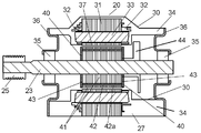
- FIG. 2 is a diagram showing the structure of the brushless motor for a washing machine according to Embodiment 1 of the present invention.
- the motor 20 that is a brushless motor for a washing machine.
- the motor 20 includes a stator 30 that is fixed to the water tub 12 of the drum type washing machine 10 and a rotor 40 that is rotatably held with respect to the stator 30.
- the stator 30 includes a stator core 31, a winding 33, a stator mold portion 34, an attachment portion 27, and a housing 36.
- the stator core 31 is configured by stacking thin iron plates, for example.
- the winding 33 is wound around the stator core 31 via the winding insulating material 32.
- the stator mold portion 34 is a mold portion provided in the stator 30 and is formed of a resin material.
- the stator mold portion 34 includes the stator core 31, the winding insulating material 32, and the windings 33 except for the gap surface 37 formed between the stator mold portion 34 and the rotor 40.
- the mounting portion 27 is formed of a resin material integrally with the stator mold portion 34 and is provided to fix the motor 20 to the water tank 12.
- the housing 36 is fixed to the stator mold portion 34 and holds the bearing 35.
- the rotor 40 includes a rotor core 41, a magnet 42, an end plate 43, and a motor pulley 25 around a motor shaft 23 that is rotatably held by a bearing 35.
- the rotor core 41 is fixed to the motor shaft 23 at a substantially central portion of the motor shaft 23, and is configured by laminating thin iron plates.
- the magnet 42 is a permanent magnet and is disposed inside the rotor core 41. That is, the rotor core 41 is formed with a magnet insertion hole 42a, and the magnet 42 is inserted into the magnet insertion hole 42a.
- FIG. 2 shows an IPM (Internal Permanent Magnet) rotor type motor 20 in which a magnet 42 is included in such a rotor core 41.
- FIG. 2 shows a configuration example in which blades 44 are attached to the motor shaft 23 for cooling the inside of the motor.
- the outer diameter of the motor pulley 25 is smaller than the outer diameter of the pulley 14.
- the pulley ratio obtained by dividing the outer dimension of the pulley 14 by the outer diameter of the motor pulley 25 is about 10, and the torque that the motor 20 must generate is reduced to reduce the size of the motor 20. That is, when the rotating drum 11 is rotated at a rotational speed of 1500 rpm, the rotational speed of the motor 20 is 15000 rpm. As described above, in the present embodiment, the rotating drum 11 is driven to rotate at an appropriate rotational speed by the motor 20 rotating at a high speed.
- FIG. 3 is a perspective view of the motor winding assembly in a state where the stator core 31, the winding insulating material 32, and the winding 33 shown in FIG. 2 are assembled.
- the winding 33 is wound around a stator tooth (not shown) in a state where electrical insulation from the stator core 31 is ensured via the winding insulating material 32.
- the winding 33 is composed of, for example, three phases of U, V, and W, and generates a rotating magnetic field on the inner peripheral side of the stator core 31 by energizing a three-phase alternating current.
- the motor winding assembly as shown in FIG.
- stator core 31 is exposed in a state where the inner peripheral side of the stator core 31, that is, the gap surface 37 where the stator core 31 and the rotor core 41 face each other is exposed.
- a stator mold portion 34 is formed so as to enclose the winding insulating material 32 and the winding 33 with a resin material. As a result, contact with the external space, that is, air is eliminated.
- FIG. 4 shows the rotor 40 shown in FIG. 2 and a bearing 35 that supports the motor shaft 23.
- end plates 43 are disposed at both ends of the rotor core 41 in the axial direction to prevent the magnet 42 from protruding in the axial direction.
- the rotor core 41 is inserted with a motor shaft 23 that is rotatably held by a bearing 35. Then, power is transmitted to the rotating drum 11 shown in FIG. 1 through a motor pulley 25 and a belt 15 disposed at the tip of the motor shaft 23.
- stator core 31, the winding 33, and the winding insulating material 32 are molded except for the gap surface 37 facing the rotor core 41.
- the stator 30 is provided with a stator mold portion 34. That is, as shown in FIGS. 2 and 3, the winding 33 through which a current is passed is included in the stator mold portion 34 and does not come into contact with water. For this reason, troubles, such as tracking, can be controlled.
- stator core 31 is also included in the stator mold portion 34 in the same manner as the winding 33, there is no fear of deterioration of characteristics due to rust of the stator core 31 except for the gap surface 37 in which the rotor core 41 always rotates opposite to the stator core 31. Therefore, the reliability of the brushless motor for washing machines is improved. Moreover, since the drum type washing machine of the present invention includes such a brushless motor for a washing machine, the reliability of the drum type washing machine is also improved.
- the IPM rotor type has been described, but the same applies to other configurations such as an SPM (Surface Permanent Magnet) rotor type in which magnets are disposed on the surface of the rotor core 41. The effect is obtained.
- SPM Surface Permanent Magnet
- FIG. 5 is a diagram showing a structure of a brushless motor for a washing machine according to Embodiment 2 of the present invention.
- the brushless motor for a washing machine shown in FIG. 5 is also used in a drum-type washing machine as shown in FIG. 1 as in the first embodiment.
- the same components as those in the first embodiment are denoted by the same reference numerals.
- the motor 120 that is a brushless motor for a washing machine according to the present embodiment includes a stator 130 that is fixed to the water tub 12 of the drum type washing machine 10 and a rotor that is rotatably held with respect to the stator 130. 140.
- the stator 130 includes a stator core 31, a winding 33, a stator frame 38, and an attachment portion 27.
- the configurations of the stator core 31, the winding insulating material 32, and the winding 33 are the same as those in FIG. 3 in the present embodiment.
- the stator core 31 is configured by stacking thin iron plates, for example.
- the winding 33 is wound around the stator core 31 via the winding insulating material 32.
- the attachment portion 27 is provided to fix the motor 120 to the water tank 12.
- the stator frame 38 holds the stator core 31 and the bearing 35 and is fixed to the water tank 12 via the attachment portion 27. 5 shows a configuration in which the housing 38a holds the bearing 35, and the stator frame 38 and the housing 38a are integrated. However, the stator frame 38 and the housing 38a can be separated. It is.
- the rotor 140 includes a rotor core 141, a magnet 42, a rotor mold portion 45, and a motor pulley 25 around a motor shaft 23 that is rotatably held by a bearing 35.
- the rotor core 141 is fixed to the motor shaft 23 at a substantially central portion of the motor shaft 23, and is configured by stacking, for example, thin iron plates.
- the magnet 42 is inserted into the magnet insertion hole 42 a formed in the rotor core 141 and is disposed inside the rotor core 141. That is, the configuration example of the IPM rotor type is also given in this embodiment.
- the rotor mold part 45 is a mold part provided in the rotor 140.
- the rotor mold portion 45 has both axial ends of the rotor core 141 so as to enclose the magnets 42 in the rotor core 141 with the gap surface 37 where the stator core 31 and the rotor core 141 face each other, with both surfaces of the rotor core 141 being sandwiched. Covers the surface.
- a motor pulley 25 is fixed to one end of the motor shaft 23 in order to transmit the power generated by the rotor 140 to the rotary drum 11.
- the motor pulley 25 is disposed on the output shaft side of the motor shaft 23 protruding from the motor body in order to connect to the belt 15. Further, the outer diameter of the motor pulley 25 is smaller than the outer diameter of the pulley 14 as in the first embodiment.
- FIG. 6 shows the rotor 140 including the motor pulley 25 and the bearing 35 disposed on the rotor 140.
- a motor shaft 23 that is rotatably held by a bearing 35 is inserted into the rotor core 141. Then, power is transmitted to the rotating drum 11 shown in FIG. 1 through a motor pulley 25 disposed at the tip of the motor shaft 23.
- the rotor 140 is configured so that the rotor mold portion 45 is disposed at both axial end portions of the rotor core 141.
- the rotor mold part 45 is formed by molding a resin material.
- the rotor core 141 is sealed inside and both ends by a rotor mold part 45.
- the brushless motor for a washing machine has both end surfaces of the rotor core 141 so that the rotor core 141 and the magnet 42 are molded except for the gap surface 37 facing the stator core 31.
- a rotor mold portion 45 is provided. That is, as described above, the magnet 42 is included in the rotor core 141, and the IPM rotor type is used.
- the rotor mold portion 45 is configured so that both end portions of the magnet 42 are completely covered. In the present embodiment, such a configuration prevents the magnet 42 from jumping out of the rotor core 141 in the axial direction.
- the magnet 42 can be prevented from popping out without using a member such as an end plate that increases the weight and cost. Further, such a configuration prevents the magnet 42 from coming into contact with water.
- a neodymium rare earth magnet is often used as the magnet 42.
- This neodymium-based rare earth magnet has a high residual magnetic flux density and can improve motor torque, but has a drawback of being deteriorated by rust. Therefore, as shown in FIG. 6, the entire magnet 42 is enclosed in the rotor core 141 by sealing both ends of the rotor core 141 with the rotor mold portion 45.
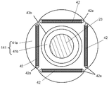
- FIG. 7 is a diagram showing a detailed cross-sectional structure of the rotor core 141 and the rotor mold portion 45 shown in FIG. 5, and FIG. 8 is a diagram showing the radial direction of the rotor core 141.
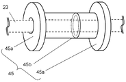
- FIG. 9 is a perspective view showing the structure of the rotor mold portion 45.
- the motor shaft 23 is inserted into the center portion of the rotor core 141.
- the rotor core 141 is provided with a plurality of magnet insertion holes 42a, and the magnets 42 are inserted into the magnet insertion holes 42a, respectively.
- FIG. 8 shows an example in which four magnets 42 are arranged.
- the magnet 42 other types of magnets such as ferrite magnets and resin-molded magnets may be used in addition to neodymium rare earth magnets.
- a through hole 43b is formed in the rotor core 141.
- the through hole 43b is a hole that penetrates the rotor core 141 in the axial direction as shown in FIG. 7, and has an annular shape in the radial direction as shown in FIG. That is, the through-hole 43b is disposed so as to extend inside the rotor core 141 as a cylindrical space from one end face to the other end face.
- a part of the rotor mold portion 45 is disposed in such a through hole 43b. That is, as shown in FIG. 9, the rotor mold part 45 has a structure in which a resin end plate part 45a disposed on both end faces of the rotor core 141 and a cylindrical resin extending part 45b are integrally coupled. ing. The resin extending portion 45 b is formed so as to fill the through hole 43 b and is disposed in the rotor core 141.
- the resin extending portion 45b is cylindrical, the rotor core 141 is separated into the outer rotor core portion 41a and the inner rotor core portion 41b by the resin extending portion 45b, as can be seen from FIGS. That is, the outer rotor core portion 41a is disposed on the outer peripheral side with respect to the resin extending portion 45b, and the inner rotor core portion 41b is disposed on the inner peripheral side with respect to the resin extending portion 45b.
- the resin extending portion 45b is made of a resin material that is an electrical insulator.
- the outer rotor core portion 41a and the inner rotor core portion 41b are insulated from each other in terms of direct current, and high-frequency current flows between the outer rotor core portion 41a and the inner rotor core portion 41b.
- the outer rotor core portion 41a and the inner rotor core portion 41b are electrically insulated and separated by the resin extending portion 45b.
- the impedance of the rotor 140 is increased and approximated to the high-impedance stator 130. As a result, the potential difference between the outer ring and the inner ring of the bearing 35 is reduced, and the occurrence of electrolytic corrosion is suppressed.
- the resin end plate portion 45a is disposed in contact with the rotor core 141 and covers both end portions in the axial direction of the rotor core 141 so as to seal both end surfaces of the rotor core 141. This prevents the magnet 42 from jumping out of the magnet insertion hole 42a, and also suppresses the intrusion of moisture, thereby preventing the rotor core 141 and the magnet 42 from being rusted. Furthermore, since the resin end plate portions 45a at both ends are connected by the resin extending portions 45b, the resin end plate portions 45a are arranged and fixed at both ends of the rotor core 141 without using screws or adhesives. Further, the occurrence of electrolytic corrosion can be suppressed by the resin extending portion 45b.
- the thermosetting resin is applied to the outer rotor core part 41a and the inner rotor core part 41b. Etc. may be integrally formed. Since the rotor mold portion 45 is configured such that the resin end plate portions 45a and the resin extending portions 45b at both ends are integrated, the rotor core 141 and the rotor mold portion 45 can be integrated by a single molding. An integrated assembly can be easily formed. In addition, the rotor 140 can be configured by inserting an assembly in which the rotor core 141 and the rotor mold portion 45 are integrated or the motor pulley 25 into the motor shaft 23.
- the drum type washing machine of the present invention includes the brushless motor for a washing machine as described above, the reliability of the drum type washing machine can be improved.
- FIG. 10 is a diagram showing a structure of a brushless motor for a washing machine according to Embodiment 3 of the present invention.
- the brushless motor for a washing machine shown in FIG. 10 is also used in a drum-type washing machine as shown in FIG. 1 as in the first and second embodiments.
- the same components as those in the first and second embodiments are denoted by the same reference numerals.
- a motor 220 that is a brushless motor for a washing machine according to the present embodiment includes a stator 30 that is fixed to the water tub 12 of the drum type washing machine 10 and a rotor that is rotatably held with respect to the stator 30. 140.
- the stator 30 is the same as that of the first embodiment, and includes a stator core 31, a winding 33, a stator mold portion 34, an attachment portion 27, and a housing 36.
- the stator core 31 is configured by stacking thin iron plates, for example.
- the winding 33 is wound around the stator core 31 via the winding insulating material 32.
- the stator mold portion 34 is a mold portion provided in the stator 30 and is formed of a resin material.
- the stator mold portion 34 includes the stator core 31, the winding insulating material 32, and the winding 33 except for the gap surface 37 formed between the stator mold portion 34 and the rotor 140.
- the housing 36 is fixed to the stator mold portion 34 and holds the bearing 35.
- the rotor 140 is the same as that of the second embodiment, and the rotor core 141, the magnet 42, the rotor mold part 45, and the motor pulley 25 are centered on the motor shaft 23 that is rotatably held by the bearing 35. I have.
- the rotor core 141 is fixed to the motor shaft 23 at a substantially central portion of the motor shaft 23, and is configured by stacking, for example, thin iron plates.
- the magnet 42 is inserted into the magnet insertion hole 42 a formed in the rotor core 141 and is disposed inside the rotor core 141.
- the rotor mold part 45 is a mold part provided in the rotor 140.
- the rotor mold portion 45 has both axial ends of the rotor core 141 so as to enclose the magnets 42 in the rotor core 141 with the gap surface 37 where the stator core 31 and the rotor core 141 face each other, with both surfaces of the rotor core 141 being sandwiched. Covers the surface.
- a motor pulley 25 is fixed to one end side of the motor shaft 23 in order to transmit the power generated by the rotor 40 to the rotary drum 11.
- the rotor 140 has the configuration shown in FIGS. 7, 8, and 9 as in the second embodiment.
- stator 30 has the same configuration as that of the first embodiment
- rotor 140 has the same configuration as that of the second embodiment.
- stator core 31, the winding 33 and the winding insulating material 32 are molded on the stator 30 except for the gap surface 37 facing the rotor core 141.
- a stator mold portion 34 is provided.
- rotor mold portions 45 are provided on both end surfaces of the rotor core 141 so as to mold the rotor core 141 and the magnet 42 except for the gap surface 37 facing the stator core 31.
- the winding 33 to which a current is applied is included in the stator mold portion 34 and has a structure that is not exposed to water. , Tracking and other problems are suppressed. Further, there is no fear of deterioration of characteristics due to rust of the stator core 31. Furthermore, by making the magnet 42 completely covered by the rotor mold portion 45, it is possible to prevent the magnet 42 from jumping out from the rotor core 41 in the axial direction and to prevent moisture from adhering to the magnet 42. As a result, there is no concern about characteristic deterioration due to rust of the magnet 42, so that it is possible to provide a highly reliable brushless motor for a washing machine with little deterioration of characteristics over time.
- the resin end plate portions 45a at both ends of the rotor core 141 are connected by the resin extending portions 45b, the resin end plate portions 45a are arranged at both ends of the rotor core 141 without using screws or adhesives. Further, the occurrence of electrolytic corrosion can be suppressed by the resin extending portion 45b. Further, since the rotor mold portion 45 is configured such that the resin end plate portions 45a and the resin extending portions 45b at both ends are integrated, an assembly in which the rotor core 141 and the rotor mold portion 45 are integrated. Can also be formed easily.
- the drum type washing machine of the present invention includes such a brushless motor for a washing machine, the reliability of the drum type washing machine can be improved.
- the resin material used for the mold is preferably a resin excellent in electrical insulation and tracking resistance, and in particular, a thermosetting resin such as unsaturated polyester resin, epoxy resin, diallyl phthalate resin, or polybutylene terephthalate.
- a thermosetting resin such as unsaturated polyester resin, epoxy resin, diallyl phthalate resin, or polybutylene terephthalate.
- a molding resin made of the above thermoplastic resin is preferred.
- inorganic fillers such as calcium carbonate, calcium silicate, talc, kaolin, mica, titanium oxide, alumina, silica, and other compounding materials may be blended in the molding resin.
- injection molding capable of high-precision molding is preferable in order to minimize variations in the amount of resin during molding.
- the brushless motor for a washing machine can improve safety and reliability by sealing the stator core and the windings using a resin material. Further, by sealing the magnet in the rotor core with a resin material, it is possible to prevent the deterioration of motor characteristics over time, and it is possible to provide a highly reliable and high performance motor. Therefore, it is particularly suitable for applications that require high reliability and high performance, such as home appliances used around water, represented by drum-type washing machines.
Landscapes
- Engineering & Computer Science (AREA)
- Textile Engineering (AREA)
- Permanent Field Magnets Of Synchronous Machinery (AREA)
- Iron Core Of Rotating Electric Machines (AREA)
- Main Body Construction Of Washing Machines And Laundry Dryers (AREA)
Abstract
Priority Applications (4)
| Application Number | Priority Date | Filing Date | Title |
|---|---|---|---|
| EP11809450.7A EP2597189A1 (fr) | 2010-07-21 | 2011-07-20 | Moteur sans balais destiné à un lave-linge et lave-linge à tambour équipé de ce dernier |
| JP2012525326A JPWO2012011274A1 (ja) | 2010-07-21 | 2011-07-20 | 洗濯機用ブラシレスモータおよびそれを備えたドラム式洗濯機 |
| CN201180035716XA CN103109011A (zh) | 2010-07-21 | 2011-07-20 | 洗衣机用无刷马达及具有该无刷马达的滚筒式洗衣机 |
| US13/696,172 US20130055771A1 (en) | 2010-07-21 | 2011-07-20 | Brushless motor for washing machine and drum-type washing machine provided with same |
Applications Claiming Priority (2)
| Application Number | Priority Date | Filing Date | Title |
|---|---|---|---|
| JP2010163564 | 2010-07-21 | ||
| JP2010-163564 | 2010-07-21 |
Publications (1)
| Publication Number | Publication Date |
|---|---|
| WO2012011274A1 true WO2012011274A1 (fr) | 2012-01-26 |
Family
ID=45496707
Family Applications (1)
| Application Number | Title | Priority Date | Filing Date |
|---|---|---|---|
| PCT/JP2011/004090 Ceased WO2012011274A1 (fr) | 2010-07-21 | 2011-07-20 | Moteur sans balais destiné à un lave-linge et lave-linge à tambour équipé de ce dernier |
Country Status (5)
| Country | Link |
|---|---|
| US (1) | US20130055771A1 (fr) |
| EP (1) | EP2597189A1 (fr) |
| JP (1) | JPWO2012011274A1 (fr) |
| CN (1) | CN103109011A (fr) |
| WO (1) | WO2012011274A1 (fr) |
Cited By (2)
| Publication number | Priority date | Publication date | Assignee | Title |
|---|---|---|---|---|
| WO2017014461A1 (fr) * | 2015-07-21 | 2017-01-26 | 삼성전자 주식회사 | Moteur de machine à laver et machine à laver le comprenant |
| US10753031B2 (en) | 2015-07-21 | 2020-08-25 | Samsung Electronics Co., Ltd. | Washing machine motor and washing machine having same |
Families Citing this family (14)
| Publication number | Priority date | Publication date | Assignee | Title |
|---|---|---|---|---|
| CN104917316A (zh) * | 2014-03-12 | 2015-09-16 | 精工爱普生株式会社 | 转子以及马达 |
| US10193417B2 (en) | 2014-12-18 | 2019-01-29 | Black & Decker Inc. | Brushless motor assembly for a fastening tool |
| CN107852053B (zh) * | 2015-08-05 | 2020-10-23 | 三菱电机株式会社 | 电动机的转子、电动机、送风机以及制冷空调机 |
| US10326323B2 (en) | 2015-12-11 | 2019-06-18 | Whirlpool Corporation | Multi-component rotor for an electric motor of an appliance |
| CN109417321A (zh) * | 2016-07-15 | 2019-03-01 | 三菱电机株式会社 | 交替极型转子、电动机、空调机以及交替极型转子的制造方法 |
| US10704180B2 (en) | 2016-09-22 | 2020-07-07 | Whirlpool Corporation | Reinforcing cap for a tub rear wall of an appliance |
| DE102016220638A1 (de) * | 2016-10-20 | 2018-04-26 | Continental Automotive Gmbh | Kraftstoffpumpe |
| TR201618089A2 (fr) | 2016-12-08 | 2018-06-21 | Arcelik As | |
| DE102017105089A1 (de) | 2017-03-10 | 2018-09-13 | Kolektor Group D.O.O. | Elektromotor |
| US10693336B2 (en) | 2017-06-02 | 2020-06-23 | Whirlpool Corporation | Winding configuration electric motor |
| CN108950971B (zh) * | 2018-07-24 | 2020-10-30 | 河南邦尼生物工程有限公司 | 一种鞋垫高效刷洗装置 |
| EP3731375B1 (fr) | 2019-04-24 | 2023-09-06 | Black & Decker Inc. | Moteur sans balai à rotor externe doté d'un ventilateur axial |
| JP7489268B2 (ja) * | 2020-08-31 | 2024-05-23 | マブチモーター株式会社 | ブラシレスモータ |
| US11473232B2 (en) * | 2020-12-09 | 2022-10-18 | Haier Us Appliance Solutions, Inc. | Motor assembly for a washing machine appliance |
Citations (5)
| Publication number | Priority date | Publication date | Assignee | Title |
|---|---|---|---|---|
| JP2001113089A (ja) * | 1999-10-18 | 2001-04-24 | Lg Electronics Inc | ドラム洗濯機の駆動部の構造 |
| JP2009078056A (ja) | 2007-09-27 | 2009-04-16 | Panasonic Corp | ドラム式洗濯機 |
| JP2009089547A (ja) * | 2007-10-02 | 2009-04-23 | Hitachi Appliances Inc | ブラシレスモータ |
| JP2009113311A (ja) | 2007-11-06 | 2009-05-28 | Canon Inc | マイクロレンズアレイの製造方法 |
| JP2009297123A (ja) | 2008-06-11 | 2009-12-24 | Panasonic Corp | ドラム式洗濯機 |
Family Cites Families (12)
| Publication number | Priority date | Publication date | Assignee | Title |
|---|---|---|---|---|
| JPS62166755A (ja) * | 1986-01-16 | 1987-07-23 | Sanyo Electric Co Ltd | 永久磁石付回転子 |
| JP2844610B2 (ja) * | 1988-09-14 | 1999-01-06 | 松下電器産業株式会社 | モールドモータ |
| JP2526144Y2 (ja) * | 1989-09-26 | 1997-02-19 | 松下電工株式会社 | 永久磁石回転子 |
| US20070152521A1 (en) * | 2004-06-24 | 2007-07-05 | Lg Electronics, Inc | Motor of washing machine |
| JP4649177B2 (ja) * | 2004-11-18 | 2011-03-09 | トヨタ自動車株式会社 | ロータおよびロータの製造方法 |
| TWI382634B (zh) * | 2004-12-15 | 2013-01-11 | 松下電器產業股份有限公司 | 具雙重絕緣構造之馬達及搭載有該馬達之電子機器 |
| US7911110B2 (en) * | 2005-01-19 | 2011-03-22 | Lg Electronics Inc. | Double rotor type motor |
| DE102006046289B4 (de) * | 2005-09-30 | 2010-11-04 | Lg Electronics Inc. | Trommelwaschmaschine |
| JP2007135332A (ja) * | 2005-11-11 | 2007-05-31 | Osada Res Inst Ltd | ブラシレスモータ及び該ブラシレスモータに用いるロータ |
| JP2007174842A (ja) * | 2005-12-22 | 2007-07-05 | Nidec Shibaura Corp | 回転子 |
| KR101397040B1 (ko) * | 2008-01-29 | 2014-05-21 | 엘지전자 주식회사 | 모터, 이의 제조 방법 및 이를 포함하는 가전 제품 |
| EP2254220B1 (fr) * | 2008-03-13 | 2017-03-01 | Panasonic Intellectual Property Management Co., Ltd. | Moteur électrique et machine électrique équipée de celui-ci |
-
2011
- 2011-07-20 EP EP11809450.7A patent/EP2597189A1/fr not_active Withdrawn
- 2011-07-20 JP JP2012525326A patent/JPWO2012011274A1/ja active Pending
- 2011-07-20 WO PCT/JP2011/004090 patent/WO2012011274A1/fr not_active Ceased
- 2011-07-20 CN CN201180035716XA patent/CN103109011A/zh active Pending
- 2011-07-20 US US13/696,172 patent/US20130055771A1/en not_active Abandoned
Patent Citations (5)
| Publication number | Priority date | Publication date | Assignee | Title |
|---|---|---|---|---|
| JP2001113089A (ja) * | 1999-10-18 | 2001-04-24 | Lg Electronics Inc | ドラム洗濯機の駆動部の構造 |
| JP2009078056A (ja) | 2007-09-27 | 2009-04-16 | Panasonic Corp | ドラム式洗濯機 |
| JP2009089547A (ja) * | 2007-10-02 | 2009-04-23 | Hitachi Appliances Inc | ブラシレスモータ |
| JP2009113311A (ja) | 2007-11-06 | 2009-05-28 | Canon Inc | マイクロレンズアレイの製造方法 |
| JP2009297123A (ja) | 2008-06-11 | 2009-12-24 | Panasonic Corp | ドラム式洗濯機 |
Cited By (2)
| Publication number | Priority date | Publication date | Assignee | Title |
|---|---|---|---|---|
| WO2017014461A1 (fr) * | 2015-07-21 | 2017-01-26 | 삼성전자 주식회사 | Moteur de machine à laver et machine à laver le comprenant |
| US10753031B2 (en) | 2015-07-21 | 2020-08-25 | Samsung Electronics Co., Ltd. | Washing machine motor and washing machine having same |
Also Published As
| Publication number | Publication date |
|---|---|
| EP2597189A1 (fr) | 2013-05-29 |
| US20130055771A1 (en) | 2013-03-07 |
| JPWO2012011274A1 (ja) | 2013-09-09 |
| CN103109011A (zh) | 2013-05-15 |
Similar Documents
| Publication | Publication Date | Title |
|---|---|---|
| WO2012011274A1 (fr) | Moteur sans balais destiné à un lave-linge et lave-linge à tambour équipé de ce dernier | |
| US9124161B2 (en) | Double-stator/double-rotor type motor and direct drive apparatus for washer using same | |
| US8987962B2 (en) | Double-stator/double-rotor type motor and direct drive apparatus for washer using same | |
| US20130042655A1 (en) | Brushless motor for washing machine, drum-type washing machine provided with same and manufacturing method of brushless motor for washing machine | |
| JP5220765B2 (ja) | Afpmコアレス型マルチ発電機及びモーター | |
| US12542459B2 (en) | Electric motor | |
| JPWO2008126408A1 (ja) | ドラム式洗濯機 | |
| JPWO2022019074A5 (fr) | ||
| JP2016208783A (ja) | モータ | |
| JP2015065789A (ja) | ブラシレスモータおよびそれを備えた洗濯機 | |
| JP5609835B2 (ja) | ブラシレスモータ | |
| JPWO2007132768A1 (ja) | モータ | |
| JP2023072105A (ja) | 回転子及び電動機 | |
| KR100917366B1 (ko) | 마그네트 매입형 비엘디씨 모터 및 회전자 | |
| JP2013059526A (ja) | 洗濯機用のブラシレスモータ | |
| KR101165411B1 (ko) | 드럼세탁기용 직결형 구동 장치 및 이를 이용한 드럼세탁기 | |
| KR200462692Y1 (ko) | 자속 집중형 전동기 | |
| KR101010836B1 (ko) | 팬 구동용 모터 | |
| WO2015181895A1 (fr) | Machine électrique tournante | |
| JP2019213417A (ja) | ブラシレスモータ | |
| KR101040959B1 (ko) | 커버플레이트를 갖는 회전자 및 그를 이용한 영구자석 동기 전동기 | |
| JP2022116648A (ja) | 回転電機の回転子およびそれを用いた回転電機 | |
| JPH11234974A (ja) | 回転電機のロータおよびロータの製造方法 | |
| US20230352994A1 (en) | Magnetic geared rotary electric machine | |
| WO2022219942A1 (fr) | Rotor et moteur électrique |
Legal Events
| Date | Code | Title | Description |
|---|---|---|---|
| WWE | Wipo information: entry into national phase |
Ref document number: 201180035716.X Country of ref document: CN |
|
| 121 | Ep: the epo has been informed by wipo that ep was designated in this application |
Ref document number: 11809450 Country of ref document: EP Kind code of ref document: A1 |
|
| WWE | Wipo information: entry into national phase |
Ref document number: 13696172 Country of ref document: US |
|
| WWE | Wipo information: entry into national phase |
Ref document number: 2012525326 Country of ref document: JP |
|
| WWE | Wipo information: entry into national phase |
Ref document number: 2011809450 Country of ref document: EP |
|
| NENP | Non-entry into the national phase |
Ref country code: DE |